1
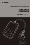
2015-02-06 V1.00.00 Note: This manual applies to iCarsoft 2nd generation serial products and CR Plus and is subject to change without prior written notice. In addition, all instructions and illustrations herein are mainly prepared based on iCarsoft 2nd generation serial products. Please kindly note that no further descriptions will be given for CR Plus as most major operation differences (excluding user interface) between iCarsoft 2nd generation serial products and CR Plus are clearly marked. iCarsoft English User’s Manual Disclaimer To take full advantage of the unit, you should be familiar with the engine. All information, illustrations, and specifications contained in this manual are based on the latest information available at the time of publication. The right is reserved to make change at any time without notice. Safety Precautions and Warnings To prevent personal injury or damage to vehicles and / or the iCarsoft Serial products / CR Plus, please read this user’s manual first carefully and observe the following safety precautions at a minimum whenever working on a vehicle: Always perform automotive testing in a safe environment. Do not attempt to operate or observe the tool while driving a vehicle. Operating or observing the tool will cause driver distraction and could cause a fatal accident. Wear safety eye protection that meets ANSI standards. Keep clothing, hair, hands, tools, test equipment, etc. away from all moving or hot engine parts. Operate the vehicle in a well-ventilated work area: Exhaust gases are poisonous. Put blocks in front of the drive wheels and never leave the vehicle unattended while running tests. Use extreme caution when working around the ignition coil, distributor cap, ignition wires and spark plugs. These components create hazardous voltages when the engine is running. Put the transmission in P (for A/T) or N (for M/T) and make sure the parking brake is engaged. Keep a fire extinguisher suitable for gasoline/chemical/ electrical fires nearby. Don’t connect or disconnect any test equipment while the ignition is on or the engine is running. Keep this tool dry, clean, free from oil/water or grease. Use a mild detergent on a clean cloth to clean it if necessary. i iCarsoft English User’s Manual Table of Contents 1. INTRODUCTION .......................................................................................... 1 1.1 ICARSOFT 2ND GENERATION SERIAL PRODUCTS ...................................... 1 1.2 CR PLUS ................................................................................................. 1 2. General Information...................................................................................... 3 2.1 ON-BOARD DIAGNOSTICS (OBD) II .......................................................... 3 2.2 DIAGNOSTIC TROUBLE CODES (DTCS)..................................................... 3 2.3 LOCATION OF THE DATA LINK CONNECTOR (DLC) .................................... 4 3. Product Descriptions .................................................................................... 5 3.1 OUTLINE OF ICARSOFT SERIAL PRODUCTS / CR PLUS .............................. 5 3.2 SPECIFICATIONS ...................................................................................... 6 3.3 ACCESSORIES ......................................................................................... 6 4. Connections & Settings ................................................................................ 7 4.1 INSTALL TF CARD .................................................................................... 7 4.2 CONNECTIONS ......................................................................................... 7 4.2 SETTINGS ................................................................................................ 8 4.3 HELP ....................................................................................................... 8 5. Diagnose .................................................................................................... 11 5.1 OBDII/EOBD DIAGNOSING .................................................................... 12 5.2 SYSTEM DIAGNOSING (FOR ICARSOFT SERIAL PRODUCTS) ..................... 14 5.2 SYSTEM DIAGNOSING (FOR CR PLUS) ................................................... 15 6. Register & Update ...................................................................................... 17 7. FAQ ............................................................................................................ 20 ii iCarsoft English User’s Manual 1. INTRODUCTION 1.1 iCarsoft 2nd Generation Serial Products nd The iCarsoft 2 generation Serial products cover the following models: MB II, FD II, VAG II, POR II, VOL II, OP II, LR II, TYT II, CP II, RT II, FT II, G-M II, NIS II and MMA II, which are especially designed for the DIY users and the servicemen of small service workshop. Featuring the color LCD display and personalized function menu, the iCarsoft Serial products support all 10 models of OBDII test for a complete diagnosis, which can diagnose full electronic control system of single vehicle model and enable you to read/clear DTCs and playback data stream in live graphic form. Moreover, the iCarsoft Serial products also feature the following bi-directional “special tests”: EVAP, O2 Sensor, I/M Readiness, MIL Status, VIN Info, and On-board monitors testing. In addition to amazing & powerful diagnosing function, iCarsoft Serial products also feature Oil/ Service lamp reset and some other special functions. It can be upgraded via TF card: Download the upgrade package into the TF card and then insert the TF card into your tool to keep it updated with the latest software version. Note: The iCarsoft Serial products may automatically reset while being disturbed by strong static electricity. THIS IS A NORMAL REACTION. 1.2 CR Plus The CR Plus incorporates over 40 diagnostic software of prevailing vehicle models covering European, American and Asian etc and supports all 10 models of OBDII test for a complete diagnosis. It enables you to diagnose four basic electronic control systems of single vehicle model (engine, transmission, ABS and airbag) and diagnosis functions include Read DTCs, Clear DTCs, Read data stream etc. Moreover, the CR Plus also supports the following bi-directional “special tests”: EVAP, O2 Sensor, I/M Readiness, MIL Status, VIN Info, and On-board monitors testing. 1 iCarsoft English User’s Manual In addition to amazing & powerful diagnosing function, CR Plus also features some special functions such as Oil/ Service lamp reset, EPB and SAS etc. It can be upgraded via TF card: Download the upgrade package into the TF card and then insert the TF card into your tool to keep it updated with the latest software version. 2 iCarsoft English User’s Manual 2. General Information 2.1 On-Board Diagnostics (OBD) II The first generation of On-Board Diagnostics (called OBD I) was developed by the California Air Resources Board (ARB) and implemented in 1988 to monitor some of the emission control components on vehicles. As technology evolved and the desire to improve the On-Board Diagnostic system increased, a new generation of On-Board Diagnostic system was developed. This second generation of On-Board Diagnostic regulations is called “OBD II”. The OBD II system is designed to monitor emission control systems and key engine components by performing either continuous or periodic tests of specific components and vehicle conditions. When a problem is detected, the OBD II system turns on a warning lamp (MIL) on the vehicle instrument panel to alert the driver typically by the phrase of “Check Engine” or “Service Engine Soon”. The system will also store important information about the detected malfunction so that a technician can accurately find and fix the problem. Here below follow three pieces of such valuable information: 1) Whether the Malfunction Indicator Light (MIL) is commanded ‘on’ or ‘off’; 2) Which, if any, Diagnostic Trouble Codes (DTCs) are stored; 3) Readiness Monitor status. 2.2 Diagnostic Trouble Codes (DTCs) OBD II Diagnostic Trouble Codes are codes that are stored by the on-board computer diagnostic system in response to a problem found in the vehicle. These codes identify a particular problem area and are intended to provide you with a guide as to where a fault might be occurring within a vehicle. OBD II Diagnostic Trouble Codes consist of a five-digit alphanumeric code. The first character, a letter, identifies which control system sets the code. The second character, a number, 0-3; other three characters, a hex character, 0-9 or A-F provide additional information on where the DTC originated and the operating conditions that caused it to set. Here below is an example to illustrate the structure of the digits: 3 iCarsoft English User’s Manual 2.3 Location of the Data Link Connector (DLC) The DLC (Data Link Connector or Diagnostic Link Connector) is the standardized 16-cavity connector where diagnostic code readers interface with the vehicle’s on-board computer. The DLC is usually located 12 inches from the center of the instrument panel (dash), under or around the driver’s side for most vehicles. If Data Link Connector is not located under dashboard, a label should be there telling location. For some Asian and European vehicles, the DLC is located behind the ashtray and the ashtray must be removed to access the connector. If the DLC cannot be found, refer to the vehicle’s service manual for the location. Figure 2-1 4 iCarsoft English User’s Manual 3. Product Descriptions 3.1 Outline of iCarsoft Serial products / CR Plus Figure 2-1 1 OBD-16 Connector Connects the iCarsoft Serial products / CR Plus to the vehicle’s Data Link Connector (DLC) via the diagnostic cable. ▲/▼Button Move cursor up or down for selection. 2 ►/◄ Button Move cursor right or left for selection; Or turn page up or down when more than one page is displayed. 3 OK Button Confirms a selection (or action) from a menu list. 4 ESC Button Exit the current program or return to the 5 iCarsoft English User’s Manual previous screen. 5 Button To retrieve the DTCs in the database. 6 LCD Display Indicates test results. 7 USB Port To connect to PC to upload data or print test results. 8 TF card slot Insert the TF card into it to update your tool. 3.2 Specifications 1) Screen: 4.0” TFT, 480*320 LCD display 2) Input voltage range: 9~18V 3) Operating current: < 500mA 4) Power consumption: < 4W (Typical) 3) Operating temperature: 32°F~122°F / 0°C~50°C 4) Storage tempetature: -4°F~158°F / -20°C ~70°C 5) Working humidity: < 80% 6) Outline dimension: 200*100*27 mm (L x W x H) 7) Weight: < 400g 3.3 Accessories 1) Main Unit 2) Main diagnostic cable 3) User’s Manual 4) USB cable 5) TF card 6) TF card reader 6 iCarsoft English User’s Manual 4. Connections & Settings 4.1 Install TF card 1) Take out the TF card from package box. 2) Insert the TF card into the TF card slot perpendicularly. Make sure is fully inserted in the right place with the “micro” label facing upward. Note: You can hear a clicking sound if you insert the TF card in the right place. Press the card slightly, it will be ejected automatically. 4.2 Connections 1) Turn the ignition off. 2) Locate the vehicle’s DLC socket. 3) Plug one end of the diagnostic cable into the OBDII 16pin connector of iCarsoft Serial products/CR Plus, and connect the other end to the vehicle’s DLC. 4) Turn the ignition on. Engine can be off or running. 5) After finishing, the system will start initializing. After initialization, the system will enter the main menu interface. See Fig. 3-1. Figure 3-1 CAUTION: Don’t connect or disconnect any test equipment with ignition on or engine running. 7 iCarsoft English User’s Manual 4.2 Settings Select [Settings] in the main menu and press [OK] to enter. Figure 3-2 1) Language This option enables you to set the user interface language. Note: Due to continuous software upgrade, language interface may differ from different software versions. 2) Unit of Measure This option allows you to set measurement unit. 3) Beeper It is used to set On/Off the buzzer. 4.3 Help This menu enables you to view device information and OBD introduction. In main menu, select [Help] and press [OK] to enter Figure 3-3. 8 iCarsoft English User’s Manual Figure 3-3 1) DLC Location Position This option helps you to find the location of vehicle’s DLC. 2) DTC Library In Figure 3-3, select [DTC Library] and press [OK] to enter the following screen. Figure 3-4 Press [►]/[◄] to move the highlight bar to different position; press [▲]/[▼] to alter the value, and then press [OK] to retrieve the definitions of the DTC. 3) Abbreviation In Figure 3-3, select [Abbreviation] and press [OK] to enter the abbreviation word list. 9 iCarsoft English User’s Manual Figure 3-5 Press [►]/[◄] to turn to next or previous page; press [▲]/[▼] to select different items, and then press [OK] to view its full name and explanations. 4) Tool Information In Figure 3-3, select [Tool Information] and press [OK] to view the related information of iCarsoft Serial products / CR Plus. Figure 3-6 Note: You are strongly recommended to note down the Serial Number and Register Code in Figure 3-6 since these 2 pieces of information are required while registering your iCarsoft Serial products / CR Plus. 5) About OBD This option allows you to have a general knowledge of OBD. 10 iCarsoft English User’s Manual 5. Diagnose Select [Diagnose] in main menu screen and press [OK], the screen will display as follows: Figure 5-1 In Figure 5-1, press [OK] to enter system, a screen similar to Figure 5-2 will appear: Figure 5-2 (For iCarsoft Serial products) Note: For different models, this page may vary from different vehicle makes. 11 iCarsoft English User’s Manual Figure 5-2 (For CR Plus) 5.1 OBDII/EOBD Diagnosing This option presents a quick way to check for DTCs, isolate the cause of the illuminated Malfunction Indicator Lamp (MIL), check monitor status prior to emissions certification testing, verify repairs, and perform a number of other services that are emission-related. In Figure 5-2 (For iCarsoft Serial products), press [OK] and the screen will enter Fig. 5-3. In Figure 5-2 (For CR Plus), press [►]/[◄] to highlight the “EOBD”, and then press [OK] to enter Fig. 5-3. Figure 5-3 Press [OK], a screen similar to Figure 5-4 will appear: 12 iCarsoft English User’s Manual Figure 5-4 It mainly includes the following functions: 1. Read Codes -- This option is used to identify which section of the emission control system has malfunctioned. 2. Erase Codes -- It is used to clear the diagnostic trouble codes. 3. I/M Readiness -- I/M Readiness indicates whether or not the various emissions-related systems on the vehicle are operating properly and are ready for Inspection and Maintenance testing. 4. Read Data Stream 5. Freeze Frame -- When an emission-related fault occurs, certain vehicle conditions are recorded by the on-board computer. This information is referred to as freeze frame data. Freeze Data is a snapshot of the operating conditions at the time of an emission-related fault. 6. O2 Sensor Test -- This option allows retrieval and viewing of O2 sensor test results for most recently performed tests from the vehicle’s on-board computer. 7. On-Board Monitoring -- This function can be utilized to read the results of on-board diagnostic monitoring tests for specific components/systems. 8. Evap System Test -- The EVAP test function lets you initiate a leak test for the vehicle’s EVAP system. Before using the system test function, refer to the vehicle’s service repair manual to determine the procedures necessary to stop the test. 9. Vehicle Information -- The option displays the Vehicle Identification 13 iCarsoft English User’s Manual Number (VIN), the Calibration Verification Number (CVN), and other information of the test vehicle. 5.2 System Diagnosing (For iCarsoft Serial products) This function is specially designed to diagnose all electronic control systems of single vehicle model. Note: Before diagnosing, please make sure the diagnostic program corresponding to certain vehicle model has been installed on your iCarsoft Serial products. Refer to the flowchart illustrated as below to diagnose a vehicle: English Select “Diagnose” Select Vehicle Manuafacturer 14 iCarsoft English User’s Manual Select Vehicle Model (Note: For different vehicles, vehicle make selection may differ. Generally we can choose a vehicle via make year. But for BENZ, we need to choose it via chassis.) Select test system Automatic (Note: This mode allows your tool to scan the vehicle test system automatically.) Manual Select (Note: In this case, you need to choose the desired system manually. Just follow the on-screen instructions to proceed.) Select test function Read version information Read fault code Clear fault code Read data stream Oil Lamp Reset More… Note: For vehicles manufactured by different vendors, it is possible that it has different diagnostic menus. For details, please follow the instructions on the screen to proceed. 5.2 System Diagnosing (For CR Plus) This function is specially designed to diagnose four basic electronic control systems of vehicle models which include the following systems: ENG (Engine) ABS (Anti-lock Brake System) TCM (Transmission Control Module) 15 iCarsoft English User’s Manual SRS (Supplemental Restraint System) Note: Before diagnosing, please make sure the diagnostic program corresponding to certain vehicle model has been installed on your CR Plus. Refer to the flowchart illustrated as below to diagnose a vehicle: Note: For vehicles manufactured by different vendors, it is possible that it has different diagnostic menus. For details, please follow the instructions on the screen to proceed. 16 iCarsoft English User’s Manual 6. Register & Update Hardware Requirement: 1. A computer that can access to the Internet. 2. A TF card reader/writer and a TF card that need to be updated. Follow the steps described as below to proceed registration and update: 1. Install the iCarsoft Serial products update tool and launch it. 2. You will be prompted to type in the Serial Number (located on the back of the tool) Figure 5-1 3. After the Serial Number is entered, click [Update] to enter Figure 5-2. Input your Email address and Register Code and then click [Submit]. Figure 5-2 17 iCarsoft English User’s Manual (If you need the Register Code, proceed to the steps 4-7) (If you have the Register Code, proceed to step 8 directly) 4. The Register Code can be found by connecting the supplied USB cord to the iCarsoft Serial products / CR Plus and inserting into the computer. 5. When the tool has powered up, highlight “Help” icon and press [OK]. 6. Select Tool Information, press [OK]. Figure 5-3 7. This is the Register Code for inputting in step 3. Figure 6 (Return to step 3 and input the code and then proceed) 8. Install the TF card from the tool into the supplied USB TF card reader and insert into USB port of CPU. 18 iCarsoft English User’s Manual 9. Reopen the update tool and select the update or click “Select All” and click “Download”. Figure 7 10. Once all steps are complete, reinsert the TF card into the tool and power the tool via USB in computer or via OBD2 port in vehicle. The tool will prompt you to upgrade, click “OK” to start updating and a progress bar will appear. It may take several minitues to finish update if your upgrade package file is too large, please wait. Figure 8 11. The registration process is now complete! 19 iCarsoft English User’s Manual 7. FAQ Here we list some frequently asked questions and answers relating to iCarsoft Serial products / CR Plus. Question: System halts when reading data stream. What is the reason? Answer: It may be caused by a slackened connector. Please turn off the iCarsoft Serial products / CR Plus, firmly connect the connector, and switch on it again. Question: Screen of main unit flashes at engine ignition start. Answer: Caused by electromagnetic disturbing, and this is normal phenomenon. Question: There is no response when communicating with on-board computer. Answer: Please confirm the proper voltage of power supply and check if the throttle has been closed, the transmission is in the neutral position, and the water is in proper temperature. Question: Why are there so many fault codes? Answer: Usually, it’s caused by poor connection or fault circuit grounding. Note: All pictures illustrated here are for reference and demonstration purpose only and this User’s Manual is subject to change without prior notice. 20 21