1
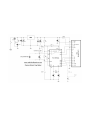
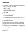
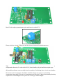
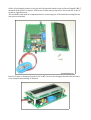
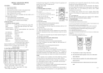
DIY Capacitor Meter Kit
Advanced Edition ver. 3.00
http://radiohobbystore.com
Components List:
Resistors:
R1 – 5% Carbon Film Resistor 1 Ohm (brown, black, gold, gold)
R2 – 1% Metal Film Resistor 3K (orange, black, black, brown, brown)
R3 – 1% Metal Film Resistor 10K (brown, black, black, red, brown)
R4, R5, R6, R7 – 1% Metal Film Resistor 1.5K (brown, green, black, brown, brown)
P1 – 500 Ohm Trimmer Potentiometer 3362P (501)
P2 – 20K Trimmer Potentiometer (203)
Capacitors:
C1, C5, C7 – Ceramic Capacitor 100nF 50V (104)
C2 – Electrolytic Capacitor 470uF 16V
C3 – Electrolytic Capacitor 100uF 10V
C4 – Axial Ceramic Capacitor 270pF NP0
C6, C8 – Ceramic Capacitor 22pF NP0 (220)
Other:
Manufactured Double Layer PCB
16x02 LCD Display
PIC16F628A
IC Socket 18 PIN
16.000 MHz Crystal
78L05 Voltage Regulator
LED 3mm Red/Yellow/Green Color
1N4007 Diode
Slide Switch Button On/Off
Tact Switch Push Button for Zero
Terminal Block for PCB
16 Pin Female Header
16 Pin Male Header
Battery Clip for 9V
2x M2.5 Standoff
4x M2.5 x 6 Screws
2x Small Alligator Clips
* R8 36 Ohm Resistor and C11 100nF Capacitor will be included only if your display require
backlight. If you are not received R8 and C11 in the kit its mean your LCD can operate without
backlight.
** Some components value and type can vary. For example, resistors can be carbon or metal
type, 1N4007 can be replaced with any of 1n4001 to 1N4005. LCD color and type are depend
on our stock. C3 capacitor can be 100uF or 220uF.
Components:
Technical Specification:
Please visit Roman Black website for more technical information and discussion:
http://www.romanblack.com/onesec/CapMeter.htm
We can't supply asm file, but PIC micro-controller is flashed with hex file from the developer.
•
•
•
•
•
•
•
•
•
•
Very High Resolution Measure: from 3 to 7 digits.
Wide Measure Range: from 0.01pF to 47uF
Simple Calibration with a Screwdriver and Multimeter
Accuracy: 1% or better
Auto-zeroing, Floating zero and Negative Capacitance (relative to zero)
Supply Voltage: 8V-12V
Supply Current: 12mA with no backlight LCD
Easy LCD 16x02 Installation
PCB improvements from older version: On/Off button
SKU: RH-K-CM-3
Display Ranges:
•
•
•
0pF to about 18000pF, format PPPPP.DD pF
18nF to 999nF, format NNN.DDD nF
1uF to 50uF, format UU.DDDD uF
The cap meter has an advanced floating zero feature. Pressing the button zeroes out any cap
value that is displayed. The meter can be zeroed any time.
The meter can display negative capacitance values compared to the zero point. So if you zero it
on a good 1nF cap, other 1nF caps tested will read as + and - the difference, so it can be used to
check cap error against a known good cap.
The second advanced feature is the auto calibrate mode. If the button is held for 2 seconds the
cap meter enables auto zero calibration. Then any time when there is no test cap connected
(<3pF on test leads) the cap meter will slowly "trim" its zero calibration by about 0.01pF every
second so that it is always correctly at zero! When in autocal mode it can still be zeroed by
pressing the button.
After zeroing it may change a few counts as the components warms up. With such a sensitive
meter it's normal to see capacitance drift by a small amount! We use in our project
temperature stable NP0 capacitor 270pF, so there is almost no temperature drift.
It's normal to have small capacitance drifts with crocodile clips wires connected because the
capacitance between the leads!
You can re-zero at any time, which may be necessary after moving the leads as this can make a
difference of 0.10 to 0.50pF or so. Of course this will not matter if you are measuring any cap
larger than a few pF!
Assembling and Soldering:
Please follow our assembling and soldering instruction steps. Print the circuit and pcb layout
and put it in front of your eyes during the soldering.
Remember do the clean solder work and install right components in the right place, because it
always hard to desolder the parts from the PCB. We cannot be responsible if you'll overheat
your PCB or will damage the kit components during wrong soldering with a mistakes. So
please double check yourself before you solder. Remember to use a solder with Rosin Core
Flux. Some industrial flux has several Mega-ohms resistance and they require a special
cleaning that cannot be performed at home.
Take your time to perform a solder work. It can take about a hour to complete the kit.
Do not apply too much solder. A good joint should look like:
Extra flux can be cleaned after with soft brush and medical alcohol. We advice you to use
0.8mm or 1.00mm thickness solder wire with low melt point:
60/40 – 186 Celsius (386 Fahrenheit)
63/37 – 183 Celsius (361 Fahrenheit)
Start soldering with resistors and axial capacitor. Install components as close to the PCB as it
possible. Cut the leads with a small flier.
If you'll need to remove excess solder from the pad, use desoldering tools (braid wick or small
pump).
Put attention to R4 resistor installed inside the IC socket. You can solder IC socket after the
resistor are soldered.
Bent P2 side adjust potentiometer pins and insert it to the PCB.
Please refer the circuit, PCB layout and the pictures during all soldering process.
Take note, C2 470uF capacitor is installed in horizontal position. Put special attention to the
components direction, it's critical for PIC, IC, diode, battery clip, led and electrolytic caps.
All possible problems comes usually from low quality of soldering, short circuits or mistakes.
R8 resistor and C11 capacitor should be installed only in case you are received this
components in package. This pair of components not affect the C-Meter functionality, but they
required for LCD backlight in case you'll use a LCD type with backlight.
Solder 16 pin female header to the pcb and 16 pin male header to the lcd board. Install 2 M2.5
standoffs with 2 M2.5 screws for LCD board. Solder battery clip wires. Insert the PIC to the IC
socket in right direction.
The finished board with all components before connecting the LCD should be looking like the
next picture attached.
Insert LCD pins to female pcb socket. Use 2x M2.5 screws for fixing the boards. Check if there
is no components touching LCD board.
The cap-meter is ready! Now you'll need to create 2 probes with alligator clips. Please use a
short wires for the probes, something about 6-7 cm (2.5-3 inch).
When you connect the 9V battery and power on the device the internal PCB capacitance + C4
270pF will be displayed on the LCD. You should adjust LCD contrast with P2 potentiometer.
If at first power up you see internal capacitance reading it's mean you are successfully finished
the kit. Now you'll need to do a simple calibration from next chapter of the manual before
using the cap meter.
If not, please check your soldering and refer the troubleshooting chapter.
Calibration:
Disconnect the battery. Use a small screwdriver to trim the resistance of R3+P1 to exactly
10.00K ohm.
Measuring Capacitors:
Power up the capacitance meter. Press zero button and connect the capacitor you need to
measure. The capacitance will be displayed on the LCD.
If the leads are shorted, or a cap larger than 50uF is connected the system times out and the
display will show "Error" and alternate between "Error" and "Large cap" as it tries to find a
cap.
AutCal Mode:
Auto zero calibrate is selected by holding the button down for 3 seconds. Auto mode can be
toggled on and off. In auto mode it will SLOWLY trim the zero point by 0.01pF per second or
so, but only when there is no cap connected. Auto mode is probably best for most cap
measuring unless you need to measure very small capacitors.
Troubleshooting:
At first, check twice if you install and solder all components due to components diagram! You
must have 5V DC reading on pin#14 of the PIC and pin# 2 of the LCD
It's no power up:
Check if you connected your power supply in proper polarity.
The LCD show some unreadable text or symbols:
Perform good connections between LCD pins. Unstable connection can cause “trash” on the
LCD display. Do not touch LCD from the back side because it very sensitive to the static
electricity and can be damaged.
I can not see any text on the LCD, only backlight led is on.
Adjust LCD contrast with R1 potentiometer.
All first line of the LCD show black cubes and there is no reaction to R1.
Internal oscillator is not working / pic not inserted correctly. Check pic orientation. Try to
replace 16Mhz crystal and 2x22pF capacitors. You can test with frequency meter or
oscilloscope at pin 16 of the microcontroller if it oscillate. Use high impedance 10M scope
probe.
Technical support:
If some components are missing or damaged please contact us and we'll provide you a
replacement.
If you are soldered the kit regarding the circuit and manual, but it's not operate, at first,
recheck if the right components are in right place and direction. If you still cannot recognize a
problem please send us support request to [email protected]
Support request requirements:
1. Please describe your problem, attach screenshots or pictures and tell what you already
tried to do for resolving the problem.
2. Attach two clear focused photos of your soldered kit, from both sides of the PCB.
3. Please wait up to 24 hours for the response.
4. Please follow our support instruction because we can help you only if you'll work with
support team. If you'll not provide a information for support team we'll not be able to
resolve the problem.
We cannot be responsible if the buyer will burn out PIC, LCD or overheat the PCB pads.
C-meter was designed to measure only discharged capacitors! Please discharge capacitors
before measuring. If you are going to measure high voltage capacitors, i. e. 10uF 250V or
similar, please use a resistor to discharge it and check with a multimeter if the any voltage
remain on the pins before you'll connect it to the C-Meters probes.
The Kit is sensitive to static electricity, especially LCD board and PIC microcontroller. Wrong
or missing ESD protection during assembling or using the C-meter can destroy it. Do not touch
the LCD board on the back side. Use antistatic wrist strap and check if the tip of your soldering
iron is grounded.
Copyrights:
Circuit and PIC software: Roman Black (c)
http://romanblack.com
PCB design and kit distributor: Alex Boguslavsky RadioHobbyStore (c)
http://radiohobbystore.com
If you want to create your own kits for sale please contact Roman Black. You cannot use our
manual text, photos, pictures or PCB design for producing your DIY kits!