1
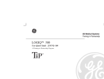
TA-CBI
Manual
Computerised balancing
instrument
309 239-02
2002-09-26
TA-CBI
USER’S GUIDE
GUARANTEE.........................................................................................................................................................3
1. PRODUCT DESCRIPTION .............................................................................................................................4
GENERAL DESCRIPTION ........................................................................................................................................4
UNPACKING .........................................................................................................................................................5
KEYBOARD...........................................................................................................................................................6
CONNECTIONS ......................................................................................................................................................7
CHARGING OF BATTERIES .....................................................................................................................................7
2. TECHNICAL DATA .........................................................................................................................................8
3. GENERAL INFORMATION ...........................................................................................................................9
CARE AND MAINTENANCE-GENERAL ....................................................................................................................9
FILTER FOR THE TA-CBI......................................................................................................................................9
QUICK COUPLINGS................................................................................................................................................9
MEASURING .........................................................................................................................................................9
4. DESCRIPTION OF PLANTS ........................................................................................................................11
5. FUNCTIONS....................................................................................................................................................13
FLOW MEASURING FUNCTIONS ...........................................................................................................................14
KV-MODE ..........................................................................................................................................................14
1. MEASURE VALVE............................................................................................................................................14
2. MEASURE PLANT ............................................................................................................................................19
2.1 ERROR MESSAGES WHEN MEASURING PRESSURE AND FLOW.........................................................................20
3. TEMPERATURE MEASUREMENT ......................................................................................................................20
4. TA BALANCE ..............................................................................................................................................21
5. TA METHODE .................................................................................................................................................27
6. LOGGING ........................................................................................................................................................28
7. MEDIA ............................................................................................................................................................30
8. PLANTS...........................................................................................................................................................31
9. PRINTING ON CBI ...........................................................................................................................................34
10. PC COMMUNICATION ....................................................................................................................................35
11. FUNCTION TESTS ..........................................................................................................................................35
12. SETTINGS......................................................................................................................................................36
6. ACCESSORIES ...............................................................................................................................................40
7. MAINTENANCE AND SERVICE.................................................................................................................41
8. CALIBRATION...............................................................................................................................................41
9. SERIAL NUMBER..........................................................................................................................................42
10. UPGRADING THE TA-CBI INSTRUMENT SOFTWARE .....................................................................43
11. WHAT’S NEW...............................................................................................................................................43
HARDWARE ........................................................................................................................................................43
SOFTWARE (VERSION PR3A)..............................................................................................................................44
2
TA-CBI
USER’S GUIDE
Guarantee
TA-CBI is guaranteed to be free of material or performance defects in normal use and service. The
guarantee period is five years, starting from and including the day of delivery. A guarantee period of
180 days applies for repairs and service. This guarantee applies only for the original purchaser and
does not include consumable materials or measuring instruments which, in TA´s opinion, have been
used incorrectly, have been neglected or have been damaged as a result of accident or abnormal use or
handling. Tour & Andersson AB guarantees that its software operates in all significant respects in
accordance with its performance specification. TA does not guarantee that its software is fault-free or
that it will operate without crashing. TA´s obligations in respect of its guarantee are restricted to full
replacement of the purchase cost or cost-free repair or replacement of defective products delivered to a
Tour&Andersson AB authorised service centre during the guarantee period, at Tour&Andersson AB’s
discretion. To claim service under guarantee, either contact the nearest TA authorised service centre or
send the product, carriage-paid (FOB) and insured, to the nearest Tour & Andersson AB authorised
service centre with a description of the problem. TA does not accept the risk of damage to the product
during transport. After repair under guarantee, the product will be returned carriage-paid (FOB) to the
purchaser. If TA is of the opinion that the fault has been caused by incorrect use, modifications,
accident or abnormal use or handling, we will submit an estimate for the cost of repairs and await
approval of this estimate before starting work. After repair, the product will be returned carriage-paid
to the customer, after which the customer will be invoiced for the cost of repair and of returning the
product (FOB).
3
TA-CBI
USER’S GUIDE
1. Product description
General description
TA-CBI is an instrument specially made for measuring in hydronic systems. It consists of a sensor unit
for measuring differential pressure and a microcomputer. The microcomputer is programmed with TA
valve characteristics and based on the measured differential pressure and valve characteristics, it
performs the flow calculation. An electric cable connects the two units. The TA-CBI instrument can
automatically correct readings affected by glycol in the water. There are programs installed for
hydronic balancing and trouble shooting. The computer unit is powered by re-chargeable NiMh
batteries, which are included. They are charged by a separate charger, which is included in the
package.
The sensor unit contains a piezo-resistive differential pressure sensor mounted in a measuring valve.
In this valve there are connections for hoses to be connected to the test points. The valve has a safety
device to protect the sensor from excessive differential pressures. A switch called the ”measuring
button” operates the valve.
It is also possible to perform temperature measurement with the separate temperature sensor connected
to the instrument unit.
With all type of measurements the measured data are stored in the instrument for later use. This can be
done by direct readout on the instrument or via a PC connected to the instrument.
4
TA-CBI
USER’S GUIDE
Unpacking
Check that all items are delivered....
1.
2.
3.
5.
6.
4.
7.
8.
9.
10.
11.
12.
13.
14.
15.
16.
17.
19.
20.
1. Instrument
2. Sensor unit
3. Case
4. Temperature sensor Pt 1000
5. Charger
6. Hoses:
400 mm
400 mm with shut off valve.
150 mm with twin needle
7. Chuck, red, for old valves
8. Chuck, blue, for old valves
9. Allen key 5 mm
10. Allen key 3 mm
11. Key STA
12. Chain for mounting
13. Manual
14. Certificate
15. CD-record
16. PC cable
17. Torx key
18 Upgrade cable
19 Measuring needles
20 Belt clip
5
18.
TA-CBI
USER’S GUIDE
Keyboard
Starting and stopping the instrument. Hold the button in for about two seconds to let
the instrument start.
There are two Enter buttons. They have exactly the same function and can be used
optionally
Is used to scroll in the menus shown on the display.
Is used to choose among units, valve types etc. that are not shown on the display
Correction of mistyped digits from the keyboard
This button is used to shut off any function and return to the main menu.
6
TA-CBI
USER’S GUIDE
Connections
RS232
6VAC
t°
∆p
Serial communication with PC
Charging of the batteries with the charger. Can also be charged from the cigarette
lighter in a car. See Accessories!
Connecting the temperature sensor.
Connecting the sensor unit
Charging of batteries
NOTE! Charge the CBI 24 hours prior to the first use.
Normally the time for charging from empty batteries is 10-14 hours.
The charging can be done at any time. The charging current is automatically controlled so that the
batteries are not damaged. When the batteries are fully charged, the current is reduced to trickle
charging. Fully charged batteries will last for at least one full working day.
A fully charged TA-CBI will be empty in approximately 1.5 month due to self discharging.
Note! The back light is very power consuming, so that the time for measurements is reduced when
using the back light.
The instrument will shut off automatically after 3 minutes to reduce the power consumption if there is
no action on the display, e.g. a button is pressed or a measurement is going on. The instrument can be
switched on and used when charging the batteries. When the charger is connected, the shut off facility
described above is not used and hence the instrument remains on until you power off.
Under the menu item 11 Function tests, you can check the condition of the batteries. (See page 35)
(see also the battery capacity bar in the main screen). When the instrument is started with a battery
capacity of less than 25 %, there is a warning message. You can however continue measuring for some
time. The instrument will shut off when the battery voltage is less than 4.2 volts.
The batteries can easily be changed. Please disconnect the charger before removing/replacing the
batteries. Remove the upper cover by unscrewing the bolts with the Torx key. The batteries are now
free and can be exchanged. Use the same type of batteries and observe how to place them.
As a last resort you can use ordinary non-chargeable batteries. Note! Such batteries must not be
charged! (The instrument will be damaged).
7
TA-CBI
USER’S GUIDE
2. Technical data
Measuring range
Differential pressure
Temperature
-9 kPa - 200 kPa
-20 °C – 120 °C
Resolution
Differential pressure
Flow
Temperature
0.01 kPa
0.001 l/s
0.1 °C
Differential pressure
Flow
Temperature
The greater of ± 1% of displayed value or ±0.2 kPa
As for differential pressure + valve deviation
< 0,2 °C + probe deviation.
Error margin
Ambient temperature
Operating
When charging
Storage
0 °C – 40 °C
5 °C – 40 °C
-20 °C – 60 °C
Humidity
Ambient humidity (not condensing)
max. 90 %RH
Electromagnetic compatibility (EMC)
According to EN 55022 class B.
IEC 801-2
IEC 801-3
Sealing
According to IEC 529, IP52
Key pad IP54
Dimensions/Weight
Instrument
Sensor unit
220*115*50 mm,
weight 875 g
145*105*55 mm,
weight 810 g
Display
Graphic LCD module with back light
Power supply
4 R6 rechargeable NiMh-batteries (1600 mAh)
Interface to PC
RS-232 9-pin DSUB female. DCE-configuration
Storage of measured data
ca 1000 valves
Logging of data
24000 measuring points
8
TA-CBI
USER’S GUIDE
3. General information
Care and maintenance-general
The TA-CBI is well protected and very easy to maintain. In order to give reliable values over a long
period of time, however, it should be given the same respect as any other measuring instrument. Do
not place loads (such as tools etc.) on the keypad or display.
Due to self discharging, the batteries need regular charging when the instrument is not used for a
longer period. To keep the batteries in good condition, it is recommended to charge the instrument
once a month when not in regular use.
Note! The instrument must be stored in a frostfree place when not in use. Never allow water to
remain in the sensor unit if there is a risk of freezing. Never leave the unit in the car (or other
unheated premises) overnight during winter.
Filter for the TA-CBI
To avoid damage on the sensor unit for the TA-CBI, the plant has to be flushed properly and the
calibration button pressed down only when the TA-CBI require it. In reality it is difficult to ensure that
the plant is flushed properly. For that reason your TA-CBI is equipped with filter.
We advise you to clean the filter frequently. To clean the filter, please use the Allen key 3 mm, which
is located in the TA-CBI case. No other tools are needed.
If the filter in the future needs to be replaced, it is not necessary to order new complete hoses. You can
order the filter separately. The filter consists of three parts as follows and order information are in
section 6. Accessories (page 40):
Quick couplings
Quick couplings are subjected to dirt and water. To prevent misfunction they need to be greased with
silicon or similar now end then.
Measuring
The measuring procedure consists of four phases:
Phase 1. Start
Switch on the instrument by pressing…………………………………..
And choose a measuring function.
Phase 2. Connection of the TA-CBI to the test points.
The two connections on the sensor unit have a red and a blue marking. The red one shall be connected
to the test point with the highest pressure and the blue one to the testpoint with the lowest pressure.
9
TA-CBI
USER’S GUIDE
If the hoses are connected in the wrong direction, the measured differential pressure is negative. If this
is the case it is absolutely necessary to disconnect the hoses and reconnect in the opposite direction.
Don’t try to measure with a negative pressure because in this case the measured value is not reliable
because it is outside the instruments valid measuring range.
Phase 3. Venting and zero calibration.
When measuring differential pressure between two points, (e.g. the test points on a balancing valve) it
is very important to look after what is happening in the lines to and from these points, so that no errors
are introduced. It is of great importance when measuring small differential pressure.
There must not be any air pockets in the hoses, or we will have an error according to the figure.1
After the TA-CBI has been connected to the test points on the valve, the hoses and the valve inside the
sensor unit must thus be vented. This will take place automatically when the sensor valve is open
(measuring button is in).
All measuring instruments are subjected to changes in the performance due to time and temperature.
The consequence of this is most important when measuring near zero2. Normally you have to make a
manual calibration (zeroing). In the TA-CBI this will take place automatically when the valve inside
the sensor part is opened (the measuring button is in).
It is therefore important to make this venting and zero calibration on every new valve.
Because of this, every new measuring function will start with a zero calibration. Repeated measurement on the same valve can be done without a new calibration.
When a measuring function is started with the sensor valve open (measuring button is in) the TA-CBI
will make an automatic zero calibration.
If a function is started with the sensor valve closed (measuring button is out), you are requested to put
in the button and then the zero calibration and the venting will take place.
Note! The function of the measure button is reversed compared to the old TA-CBI and DTM-C.
Phase 4. Measuring
When the measuring button is released, the flow through the valve in the sensor is stopped and the
sensor is subjected to the differential pressure over the balancing valve. The instrument will make a
number of measurements (~ 20) over a period of 1.5 sec. The average value of these measurements is
then presented on the display. This is repeated at 1.5 sec. intervals.
1
The minimum recommended ∆p=3 kPa. If there is an air bubble in the hose where b=1cm (see figure above)
the error introduced is
Error =
b
0,01
=
* 100 = 3.3%
Dp 3 * 0,1
2
It is of great importance to be aware of the instruments characteristics when measuring small differential
pressures. The error margin at differential pressures below 20 kPa are 0,2 kPa. Therefore the relative error E
rises when the the differential pressure shrinks. The error at minimum recommended ∆p=3 kPa is
Error =
0,2
* 100% = 6,6%
3
10
TA-CBI
USER’S GUIDE
4. Description of plants
To be able to use the CBI instrument efficiently, it is necessary to structure the information about the
hydronic system. This information is stored in a plant. The plant is divided into groups of valves called
modules and of course the valves itself. The following figure shows the plant structure:
Names of plants, modules and valves have the following limitations in the TA-CBI instrument.
Plant name:
maximum of 19 characters can be used
Naming a plant can only be performed in TA SelectII
Module name: maximum of 10 characters can be used
Naming a module can only be performed in TA SelectII
Valve name: a maximum of 10 characters can be used
Naming and renaming a valve is possible both in TA-CBI and in TA SelectII
Valve number: Each valve has also an associated valve number (in previous versions of TA-CBI
numbers was used instead of names). This number is still used in the TA-CBI and can
be between 1-255.
The next figure shows what could be a maybe more realistic naming of a plant.
11
TA-CBI
USER’S GUIDE
Both valve data e.g. type, size, name and desired flow are stored and can be used when measuring the
system and/or the valve. When the valves are measured, the measured data are stored in the same
structure and can be used later on. Next figure shows the information stored with each valve, both
design data, measured and calculated data. This is divided into two groups depending on whether it is
a TA valve (valve 1) or if Kv-values (valve 2) is used.
TA-CBI:s main menu item 1. Measure valve (page 14) has a somewhat simplified usage of plants.
Here it is not necessary to create a plant, the measuring can start right away. Beneath the surface this
meauring function use a plant but it can be a ”ready made” one and valves are created automatically
when measuring if it is necessary.3 There is one ”ready made” plant created in the TA-CBI, it is plant
P0 with module M0. If you want to reset and start all over again see in section in 8. Plants (page 31)
how to do that.
Measured values are stored in the instrument and can be recalled later. If a new plant should be
measured it is probably a good idea to erase measured data before measuring starts. How to clear the
memory are covered in section 8. Plants (page 31).
Logged data
Logged data e.g. pressure, flow and/or temperature can be logged during a longer period. This data is
not associated with the plant structure. Saved loggings are not erased even if all plants are erased.
Usage of logging are covered in section 6. Logging (page 28).
3
This is possible with the other measuring functions too, but this is not the intended usage.
12
TA-CBI
USER’S GUIDE
5. Functions
When you have started the TA-CBI, this picture is shown: ………………
This is the main menu. It consists of a list with a number of functions
concerning measurements, data transfer, settings and so on. Behind these
menu items, there are in some cases submenus with new functions.
The second line shows TA-CBI software version and the selected mode,
TA-Mode or Kv-Mode (explained in section 7 Kv-Mode, page 37).
The third line displays the remaining battery capacity (0-100%), here 60%.
When the bar is filled to 25% there is a warning message displayed as
indicated in the section about Charging of batteries (page 7).4 When this
happens, it is important to charge the batteries as soon as possible to avoid
unneccessary disruption. Saved measured data are not lost even if the
battery capacity is zero. However the instrument cannot be used before
charging.
The function you want is selected by pressing
and
or directly by pressing the corresponding number and
The dark field is a ”pointer” that shows which alternative that has the focus.
If the menu is too long to be shown on one screen, there is a small vertical
arrow in the right part of the screen.
you scroll through the menu. The arrow indicates in which
With
direction/directions it is possible to scroll.
The following menu items (functions) are available:
1 Measure valve
2 Measure plant
3 Temp. measurement
4 TA BALANCE
5 TA Method
6 Logging
7 Media
8 Plants
9 Printing on TA-CBI
10 PC communication
11 Function tests
12 Settings
4
See also section 8 Default system (page 39) about resetting the system.
13
TA-CBI
USER’S GUIDE
Flow measuring functions
Menu item 1 - Measure valve, menu item 2 – Measure plant and
menu item 4 - TA BALANCE are the main measuring functions.
Menu item 1 - Measure valve is the most straightforward method that
can be used without defining plants, modules and valves. It can be used
both in TA-Mode (with TA products where flow characteristics are stored
in the instrument) or in Kv-Mode. In TA-Mode the method can be used
with water or other media. If preferred new valve settings can be calculated
based on measured ∆p.
Menu item 2 – Similar to menu item 1 – Measure valve with the
difference that it requires a plant with modules and valves predefined. Can
be used in TA-Mode and Kv-Mode. Only TA-Mode works with other
media than water. This function is also used when making the verifying
measurements after measuring with the TA BALANCE method.
Menu item 4 – TA BALANCE is the most sophisticated method. It
requires a predefined plant but it is also possible to rearrange, add new and
delete valves. It works only in TA-Mode and with water as media. TA
BALANCE measures all valves in a module and then calculates the desired
handwheel settings to achive desired flows.
Kv-Mode
Usage of Kv-Mode is covered in section 7 Kv-Mode (page 37) but please
read this chapter first for general knowledge about measuring functions.
1. Measure valve
This function is used to measure differential pressure and flow
measurement.
Choose this menu item when you have not prepared the measuring before
by feeding the information about the valves according to 8. Plants (page
31)5. Do you want to measure on valves already fed into the TA-CBI, you
should use menu item 2. Measure plant (page 19).
5
It is however possible to measure predefined plants with menu item 1 but this is not recommended. In such a
case beware of the fact that you have to select plant and module before entering menu item 1 – Measure plant.
Also if you have a predefined plant but want to measure on the default plant/module P0/M0 you have to select
the plant/module before entering menu item 1 Measure valve. This is explained in section 8. Plants (page 31).
14
TA-CBI
USER’S GUIDE
The measurement start with a differential pressure measurement. Perhaps
you want to measure over a pump. Please be aware of the fact that you can
not measure a differential pressure higher than 200 kPa.
If you are measuring on a TA valve, you can directly go on with a
measurement of the flow (which is based on the differential pressure
measurement that is going on) in this valve. If it is another valve with
known Kv-Value please see section 7 Kv-Mode (page 37).
You can also choose not to go on but save the differential pressure
measurement.
Connect the TA-CBI to the valve acc. to section Measuring (page 9)
On the TA-CBI, move the cursor (dark line) to 1. Measure valve…………
or press button 1 and
And press
Now the deaeration and the zero-calibration will take place.
Follow the instructions on the screen. If the measure button is
out:……………………… ………………………………………………..
When you have pressed the measuring button, or if the measure button is
in, when you start…………………………………………………………..
And soon………………………………………………………………….
When the measure button is out again, the TA-CBI will start to measure and
the differential pressure is presented in the last used unit…………………
The unit can be changed with keyboard buttons
The chosen unit will be kept until you change again even if you shut the
TA-CBI off.
You can now proceed by pressing
The display will read………………………………………………………
There are tree alternatives:
1. Measure flow. Go on with flow measurement on the valve. The
differential pressure measurement is running all the time.
15
TA-CBI
USER’S GUIDE
2 Save diff. pressure. The differential pressure measurement can be
saved. This is done in the same way as with a flow measurement (of course
there is only a differential pressure to save then), and will be explained after
the section about flow measurement.
3. Cancel . Means return to the main menu.
If you choose 1 Measure flow, by pressing
the TA-CBI will ask what
kind of valve you are measuring on. A suggestion is shown (the latest one
used)……………………………………………………………………
The cursor is on the line Type:.. Choose the valve type with
When you are satisfied, press
or
The cursor will jump to the next line. In the same way, choose valve size.
Press
Now the TA-CBI will ask for the hand wheel position of the valve………
Give the hand wheel position with the numeric keypad and press
If you are measuring on a valve without adjustment possibility e.g. TALOOP, this screen will of course not appear.
If you give a position that is not valid, e.g. 5.2 turns on STAD 20, there will
be an error message…………………………………………………………
Press
The first picture will reappear. Give a new value!
The flow is presented in the last used unit…………………………………
The Kv-value of the valve at the present handweel position is shown.
The flow unit can be changed with
indicate the line with the flow display.
. First you have to use
to
The differential pressure unit is the one you have chosen during differential
pressure measurement………………………………….……………………
You can change the hand wheel position direct in this screen………………
Write e.g. 2.1. The display of the flow will dissapear until you confirm the
hand wheel position entered by pressing
16
TA-CBI
USER’S GUIDE
Then the display read………………………………………………………
With
you can go back to the line Handw. pos. and repeat.
The second last line indicates that you are measuring in normal water, that
is, there is no anti-freeze or other additives in the water. If you have chosen
to measure on any other media than water, for instance Ethylene glycol in
section 7. Media (page 30), this will be shown in the last line.
If you want to save the measurement or change the hand wheel position of
the valve, press
Then the display will show (after some pressing on
)…………………
There are more alternatives in the menu (use the arrow keys
if you
want to see all of them)……………………………………………………
1 Save
The measurement must have a name and a place where it can be saved.
If you have not yet told the TA-CBI anything else, it will suggest that the
measurement should be saved automatically in the default plant P0 and
module M0………
The measurement will be stored in the actual plant and module with the
next consecutive number.
Selection of plant and module must be performed before starting with the
measurements if you want to select something else than the default plant or
if you have selected another plant in a previous session. You will find a
brief explanation about plants in section 4. Description of plants
(page 11) and about creating, selection and usage of plants in section 8.
Plants (page 31).
There is also a possibility to give the valve a name. It can be the name on
the drawing or similar. Up to 10 characters are recognized.
Use
to scroll the characters, and
keys can of course be used………
to change position. Numeric
If there are already other plants and modules in the TA-CBI, you can use
one of these to store the measurement in.
17
TA-CBI
USER’S GUIDE
2 New position.
You are not satisfied with the result of the measurement, and want to make
a new one with another hand wheel position. You will come back to the
picture about Handwheel position and a new flow can be measured. This
can also be done directly in the flow screen as described abowe.
3 Computer method
This function is used to help adjusting a valve to a certain desired flow. The
method is based on measuring the valve in two different settings
(positions). One is an arbitrary position e.g. a calculated one and the other
one is in closed position where you measure the differential pressure. If you
are not allowed to close the valve completely, then close it as much as you
can. There will be a reasonably good calculation anyway. From these two
measurements the TA-CBI calculates the position that will give the desired
flow. The method is based on some assumptions that are not always exactly
right, so that you may not have exactly the right flow on the first try. An
improved value can be calculated taking into account this last
measurement. This can be repeated until you get an acceptable value.
Working procedure:
Give the desired flow………………………………………………………
And press
if necessary.
Change unit with
A differential pressure measurement has to be done with the valve closed…
Shut the valve and press
The result of the ∆p measurement is presented……………………………
Let the value stabilise for a few seconds and go on by pressing
If you can not or are not allowed to fully shut the valve, shut as much as
possible, there will still be an answer (somewhat less accurate).
The TA-CBI will calculate a hand wheel position to adjust in order to get
the desired flow……………….……………………………………………
It may happen that it is not possible to get the desired flow in this plant
with this valve. Then there is an error message……………………………
and the TA-CBI give the possibility to enter another flow and the
procedure is repeated.
18
TA-CBI
USER’S GUIDE
When you have got an answer (Handweel position to adjust), you can
immediately make a flow measurement. Adjust the valve to the suggested
position and press
The TA-CBI start measuring in the same way as a normal flow
measurement...………………………………………………………………
Press
A menu with three choices appears…………………………………………
If the measure value is not good enough, press
1 Recalculate and the TA-CBI will recalculate and present a better
estimation of the hand wheel position. This can be repeated until you are
satisfied.
If the flow is ok, choose 2 Save to save the measurement in the way that
has been described before or press 3 Cancel to return to the main menu.
2. Measure plant
This function is also used to measure differential pressure and flow. Choose
this menu item when you have already input flow details about the valves
according to section 8. Plants (page 31) or the TA SelectII program.
You may have used main menu item 1. Measure valve before and saved
some measurements, but you want to recall one of them to make a new
measurement.
This function is also used to make the verifying measurements after having
used the TA BALANCE method (page 21).
The procedure will start by asking where to find the valve
(Plant , Module)……………………………………………………………
Choose plant with
and
and…………………………………………………………………………
choose module with
and
Select the desired valve in plant test and Module mod1.
In this case…………………………………………………………………
or keyin)
(with
Press
19
TA-CBI
USER’S GUIDE
From this point, the procedure is the same as in 1 Measure valve
(page 14). All the stored data (valve type, size, desired flow) will appear on
the display, but they can all be changed during the procedure.
The only thing that differs, is the procedure when the measurement is going
to be saved.
If there already is a measurement on that valve, the TA-CBI asks…………
and you can choose 1 Yes to overwrite or 2 Cancel.
2.1 Error messages when measuring pressure and flow
When measuring flow, it must go in the expected direction. If the flow is in
the opposite direction, (you may have interchanged the hoses) the display
will show………………………………………………………………….
When measuring pressure, the pressure will be shown with negative sign.
OBS. This reading is correct only if the value is abowe ca - 9 kPa.
For the flow measurement to be reliable, the measured differential pressure
must not be too small (to big error). For this reason there is a limit at 0.5
kPa, below which there will be no flow presentation, but instead an error
message................................................................................…………….
To get a reading, throttle the valve a little, until you get a reading.
TA recommends 3 kPa as the lowest differential pressure for good
accuracy. If you measure below 3 kPa but over 0.5 kPa, there will be a
warning message………………………………………………………..
You can still make the measurement.
3. Temperature measurement
First connect the Pt-1000 sensor. The sensor can be inserted into the test
points of a STAD or STAF valve. In that way the measurement will take
place in the media.
On the TA-CBI, move the cursor to 3 Temp. Measurement and press
or press button 3 and
The display will show………………………………………………………
Change unit between °C and °F with
If you try to make a Temperature measurement without having connected
the sensor, there will be an error message…………………………………
The measuring starts as soon as the sensor is connected and
20
is pressed.
TA-CBI
USER’S GUIDE
4. TA BALANCE
The TA BALANCE program, which is programmed into the balancing instrument TA-CBI, is based upon
the Compensated Method. The program calculates, after having done some measurements, the correct
settings of the balancing valves in order to achieve the desired flows.
The program assumes that the plant can be divided into modules. A module is created by several circuits
connected being to the same supply and return pipes. Each circuit has its own balancing valve and the
module has a common balancing valve, called the Partner valve.
In a radiator plant, the first operation is to pre-set the radiator valves for the calculated flows. These
calculations are normally based up on a differential pressure of 10 kPa across the radiator valves.
In order to get enough differential pressure across the balancing valves to ensure accurate measuring, shut
off the other modules and open fully the relavent partner valve. Set the balancing valves in the module on
the calculated values, if any. If there are no calculated values, set the balancing valves on 50 % opening
(STAD = 2 turns).
The program states that the valves are numbered according to the diagram, that is the first valve after the
partner valve must be number one. The other valves are then numbered in sequence. The measuring
procedure can, however, be carried out in optional order.
Measure one module at the time. TA-CBI gives directions on the display of each step in the procedure.
These steps are:
1. Give type, size and actual position (e.g. STAD, DN 20, 2 turns).
2. Give the desired flow.
3. A flow measurement is automatically performed.
4. Shut the valve completely.
5. A differential pressure measurement is automatically performed.
6. Re-adjust the valve hand wheel to it´s original setting.
When this procedure has been carried out for all balancing valves in the module, the TA-CBI calculates the
correct settings for the valves within the module. Adjust the valves to these settings.
TA-CBI has ”discovered” the index circuit (the circuit with the highest resistance), and have given the
concerned valve the minimum differential pressure that is necessary to measure a correct flow. This value is
normally 3 kPa, but can temporarily be changed if desirable (menu item
4 Min dP in TA-BAL (page 27) explains how to change this setting).
At this moment, the correct flows are not yet achieved. This will happen when the partner valve has been
adjusted to its correct flow. This operation is, however, carried out later on in the procedure.
When all the modules in one riser have been balanced individually, these modules must be balanced
between themselves. Each module is now looked upon as a terminal, whose balancing valve is the partner
valve in the module.
21
TA-CBI
USER’S GUIDE
This new module should now be measured and calculated in the same way as described earlier. After that,
all the risers create a module that is balanced accordingly. Finally, the total flow is adjusted with the main
balancing valve. When this operation is completed, all the circuits in the plant will have the desired flows.
For verifying this, flow measurements can be done on some valves.
To get the best possible result, a measurement on the Partner valve is included in the method. But
sometimes there is no partner valve. It is however possible to make the measurements on the other valves,
and get a result. To do so, you have to tell the TA-CBI, that there is no Partner valve. This is done in main
menu 4 TA BALANCE and 3 Partner valve (page 27)
Working procedure:
Connect the TA-CBI to the valve. On the TA-CBI, move the cursor (dark
line) to 4 TA BALANCE and press
or press button 4 and
The TA-CBI start by asking what kind of module you are going to work
with…………………………………………………………………………
1 New module means that a new module has to be made in the TA-CBI
now.
2 Existing module means that the measurement is going to take place in
a module that already exist in the TA-CBI. It can be a module that was
loaded from the PC or the module could have been made with 1 New
module earlier.
In the first alternative (1 New module) there must be a place in the
instrument to store the data. First choose the plant…………………………
and press
If nothing else has been said, the default plant P0 will be used.
Then you give a module……………………………………………………
and press
If nothing else has been said, the default module M1 will be used.
If you try to use an already used module, there will be an error message.
Press
and give a new module.
22
TA-CBI
USER’S GUIDE
Give number of valves in module (partner valve not included)…………
and press
The display show…………………………………………………………
You start the measurements by choosing 1 Measure next.
and press
Select the actual valve to measure with
and press
or number buttons…………
Remember that the numbering of valves in the module must be done in the
right way! That numbering is done here. See section 8. Plants (page 31).
Select valve type with
and press
and then valve size with
and press
………………………………………………
Give the design flow with numeric buttons…………………………………
and press
The unit can as usual be changed with
Give the handwheel position that the valve has now………………………
and press
This position must not be changed during the measuring of the other
valves in the module.
Now the zero-calibration will take place. Follow the instructions given in
an earlier section.
A flow measurement will take place and is presented………………………
The measuring goes on until you interrupt. When the value is stable,
press
23
TA-CBI
USER’S GUIDE
Then the display will show…………………………………………………
Shut the valve completely and then press
∆p across the valve is measured and presented……………………………
When the value is stable, press
The display shows…………………………………………………………
Or if it is the partner valve…………………………………………………
Press
You are asked to reopen the valve to the previous position before you go to
the next valve.
This is important and it applies also to the Partner valve in the case
where you measure on the Partner valve before any of the other valves
in the module.
After each valve is measured, the display will show………………………
Repeat the measuring procedure on all valves in the module.
If you have choosen to measure on the partner valve in the TA-BALANCE
menu , 3 Partner valve (page 27), you have to make this measurement
before the calculation can take place.
(Menu item 2 Name valve let you change the valve name. This works
the same as is described in section 1. Measure valve (page 14).)
When there are measurements on all valves in the module, this picture will
show…………………………………………………………………………
Here you can let the TA-CBI make the calculation or you can do a new
measurement on some valve that you have done wrong.
You can also make some adjustments in the module. This will be explained
later.
24
TA-CBI
USER’S GUIDE
If you choose to measure on 2. Existing module……………………………
you have of course to select this module.
Press
and select the plant (where the module is) with
Select the module with
…………
and press
The module can look different depending on how it has been “made”. The
module is loaded and TA-CBI will recognise the number of valves and will
check if perhaps all valves have stored measurements. If so it is possible to
make a new calculation………………………………………………………
If not, the display shows……………………………………………………
In both cases new measurements can be made and it is even possible to
make some adjustments on the plant regarding number of valves or
placement of the valves.
a) You may discover that in fact there is one (or more) valves that you did
not know of…………………………………………………………………
If you want, give the valve a name, choose Type and Size…………………
with
and press
25
TA-CBI
USER’S GUIDE
Then give design flow and press
………………………………………
Now the TA-CBI renumber the valves and this valve has to be measured,
so the TA-CBI returns to……………………………………………………
b) You may discover that you have measured a valve that is not part of this
module ………………………………………………………………………
c) You may discover that you have made a mistake when making the
numbering of the valves. Then you can “move” valves. Example: You have
measured on a STAD 25 and given it no 3 and on a STAD 20 that has been
given no 5. In reality the STAD 20 should have no 3. Then you can ”move”
no 5 to position 3. The STAD 25 will be renumbered to 4 and the old no 4
be a new no 5………………………………………………………………
Now a new measurement can be made. Note! If you want to move in more
steps, remember that the number of some valves will change in every step.
It is also important to keep in mind, that changes in the hand wheel
positions or pressure and flow situation must not occur in the module
during these corrections. Otherwise the old measurements cannot be used.
After calculation the result can be studied …………………………………
Scroll among the valves with
The result is automatically stored.
The index valve is the valve in the circuit with the highest resistance.
Pressing
in this menu, will take you to this…………………………
26
TA-CBI
USER’S GUIDE
3 Verify TA-BAL
When the system is measured with TA BALANCE and the system have
been adjusted according to calculated settings then maybe you want to
make verifying measurements. With menu item 3 Verify TA-BAL you can
do that. This menu item is the same as main menu item 2 – Measure plant
so it’s possible to select either of these menu items. If you wan’t to proceed
se explanations in section 2. Measure plant (page 19).
3 Partner valve
In TA BALANCE , you can choose to measure on the partner valve or not.
The best result is obtained if you can measure on the partner valve, but it is
not always possible. (Perhaps there is no such valve!) It is possible to
change this setting when you measure the module if you find that there is
no partner valve, it is not necessary to change the setting before the
measurements of valves start.
4 Min dP in TA-BAL.
If there is a need for that, the value ∆pmin (the minimum ∆p taken in the
index valve) that is used in the calculation can be changed. This value,
normally 3 kPa, can be changed in menu 4. TA BALANCE and
4 Min dP in TA-BAL (page 21). 3 kPa should be considered as a
minimum value.
Remember to put it back again!
The calculated values (positions) are stored and will appear automatically
when making verifying measurements on the valves.
They can also be printed from PC with the TA SelectII program.
5. TA Methode
This function is used to calculate the position of a valve, corresponding to a
given flow and differential pressure. It is used e.g. to adjust the module
valve in the TA-Metoden.
Move the cursor to 5. TA Metoden and press
or press 5 and
Choose valve in the same way as described earlier…………………………
Press
Give desired flow ……………………………………………………………
and press
27
TA-CBI
USER’S GUIDE
Give desired ∆p ……………………………………………………………
And press
TA-CBI will present the calculated position………………………………
With
you can calculate a new case.
The combination of desired flow and pressure must result in a Kv-value
that the valve chosen can produce.
Otherwise there will be error messages……………………………………
or……………………………………………………………………………
6. Logging
This function is used to study any fluctuations of measured units over a predetermined time period. Differential pressure, flow or temperature can be
studied.
The measurements are stored automatically according to a given interval of
time. Up to 24000 measure points can be stored, corresponding to between
20 hrs and 65 days depending on the time interval chosen. You can make
several logged measurements, but the total number of points is 24000.
Measurements stored with other functions and logging are stored
independently.
Note! If logging is going to last more than a couple of hours, you have
to charge the batteries by having the charger connected all the time.
Connect the TA-CBI to the valve according to section Measuring (page 9),
or if you want to log temperature, connect the temperature sensor
Move the cursor to 6 Logging and press
or press button 6 and
28
TA-CBI
USER’S GUIDE
Choose the place where you want to place the logging. You can choose the
same valve as in save………………………………………………………
Choose the kind of logging you want to do. You can logg Pressure or Flow
or Temperature or Pressure and Temperature or Flow and Temperature
The last two functions will of course take twice as much memory.
Give the interval (in seconds) that you want to use…………………………
Min interval is 3 sec and max interval is 240 sec (4 min).
TA-CBI shows the time (in hours) you can logg with the choosen interval
and all available memory. If you do not want to use all the memory, change
logging time and press
You will be informed about how much of the available memory (in total)
that will be used according to your choice.
You can go back to previous screen by 2 Reselect and change.
You can start the logging at a predefined time………………………………
Change with numeric keys.
If you do not make any change, the logging will start immediately.
To log flow you must select appropriate valve and handwheel position……
Select and press
29
TA-CBI
USER’S GUIDE
The logging will start and the measurement is shown………………………
Note! The measured value will be presented during the logging, but it is
updated only once each interval.
The logging is interrupted with
or by switching the TA-CBI off.
To see the result use 9. Printing on CBI (page 34) or 10. PC
communication (page 35) to transfer it to the PC.
Erase logging
In the main menu move the cursor to 6 Logging and press
or press
button 6 and
. In the next step select menu item 2 Erase logged
data and press
Select item 2 Yes if you want to erase all logged data………………………
7. Media
Flow measurements are normally done with pure water. In some cases you
are forced to use anti freeze e.g. glycol. Then the relations between flow
and ∆p in a valve is changed. The magnitude of this change depends on a
number of things, like the size of the valve, the hand wheel position and of
course the kind of media used. The factors most critical are density and
viscosity. Higher density and viscosity will result in a smaller flow at the
same ∆p across the valve compared to that at pure water.
The TA-CBI will measure ∆p correctly and correct for the influence of
change in density and viscosity to show the right flow. Different glycol’s,
alcohol, brine can be used.
Note! This correction can only be made with TA-valves (STAD, STAF,
TBV, TBV-C), and is not applicable for TA Balance or Computer method.
Selected media is associated with the selected plant. When changing
plant the media is changed too.
In a sub menu you find some alternatives…………………………………
In the first two cases, the TA-CBI will calculate density and viscosity from
% of glycol used……………………………………………………………
30
TA-CBI
USER’S GUIDE
and temperature……………………………………………………………
In case 3 Other, you must know the density and viscosity of the liquid…
and…………………………………………………………………………
The value for water at 20 °C is 1 mm2/s
The TA-CBI will use these settings until you change.
So, do not forget to reset to water!
In case 4 Reset to water you change back to normal water again.
When measuring flow, the chosen media will be shown.
8. Plants
This function is used to create plants, modules and valves. The TA SelectII
program is a better option because it is easier to use and make more options
available. This menu item only makes basic abilities available.
If no plants have been defined the CBI will contain one plant (P0)
containing one module (M0) and the module contains one valve (1). This
“ready made” plant is used when using measuring function 1. Measure
valve (page 14) if no other plants exist. This can also be used with the
other measuring functions but this is not the intended usage.
Choose 8 Plants in the main menu…………………………………………
and press
31
TA-CBI
USER’S GUIDE
and then select menu item 1 Plants………………………………………
and press
Choose menu item 1 Select plant…………………………………………
and select plant………………………………………………………………
with
and
Choose menu item 2 Add plant if you want to add a new plant…………
and select plant to add………………………………………………………
with
and
Plant names are predefined in the range P1... P10.
Choose menu item 3 Delete plant if you want to delete a plant…………
Select the desired plant………………………………………………………
with
and confirm with
. The plant with all modules and valves
will be deleted immediately.
OBS Default plant P0 cannot be deleted.
To select, add and delete modules are performed in a similar way. Valves
are different when it comes to selecting and adding but deleting a valve is
the same as deleting a plant or module.
Select menu item 3 Valves…………………………………………………
Choose menu item 1 Select valve………………………………………
with
and
32
TA-CBI
USER’S GUIDE
and select the valve…………………………………………………………
with
and
in the next step select a proper name………………………………………
It can be the name on the drawing or similar. Up to 10 characters are
recognized.
to scroll the characters, and
Use
keys can of course be used
to change position. Numeric
Choose menu item 2 Add valve if you want to add a new valve…………
with
and
Now you have to select preferred valve type and size………………………
Use
to change line, and
to change type/size. Continue with
Give design flow……………………………………………………………
Continue with
in the next step select a proper name………………………………………
It can be the name on the drawing or similar. Up to 10 characters are
recognized.
Use
to scroll the characters, and
keys can of course be used
to change position. Numeric
The last menu item 4 Erase saved data erase all plant data including of
course measured data stored in the TA-CBI.
33
TA-CBI
USER’S GUIDE
Select item 2 Yes if you want to erase all plant data………………………
This erases all data including measured data in plant P0.
9. Printing on CBI
This function is used to show saved and logged measurements on the TACBI display. (Printing to and from a PC, is done with 10 PC
communication).
Choose 9 and press
Then you will see……………………………………………………………
Saved data are collected in plants. Select the desired plant with
………………………………………………………………………
Select the module with
Then you can select any valve in this module with
It will take a second or two to update the values on the screen……………
Logged measurements are saved in time order. Select the actual logging
with
There are two possibilities to study the result:
• An overview, where the complete curve is shown on the display.
No values are shown here……………………………………………………
• A detailed graph, where the curve is divided into parts so that you can
see all the details……………………………………………………………
In the second case, there is a cursor, which can be moved with
When you press one of the keys, the cursor will move one step. Holding it
down will cause the cursor to repeat moving.
With this cursor, you can read every point on the curve.
34
TA-CBI
USER’S GUIDE
To see the different parts of the curve, use
The value is shown by pressing
10. PC communication
With this function you transfer data to and from the PC. The transmission is
done with the PC cable, that comes with the TA-CBI. It is connected into
the RS-232 port on the TA-CBI and into the COM1 or COM2 port of your
PC.
TA SelectII is the program to use for communication, create plants, save
and analyze measurings. Read in the TA SelectII User’s Guide about how to
build a plant, transfer plants and transfer measurements to/from the TACBI.
To use the programs in connection with the TA-CBI, you must connect the
cable, then start the TA-CBI and press 10 PC communication . The TACBI will show………………………………………………………………
It is now ready to communicate. Then start the TA SelectII program. This
program controls what will happen.
11. Function tests
Available items are:
1 Battey condition
2 Pressure offset
3 Battery temp.
4 AC supply
With 1 Battery condition, you can check the condition of the battery,
such as remaining capacity, the current consumtion and voltage.
With 2. Pressure offset, you can read the output voltage from the sensor
at the zero-calibration. This reference voltage should be 0.10 to 0.25 V.
Nominal value is 0.176 volt. A bigger deviation than stated above, indicates
a possible error in the sensor unit.
If this should be the case, an error message is shown every time you start
measuring.
35
TA-CBI
USER’S GUIDE
3 Battery temp. The battery temperature must not exceed 40°C when
charging.
4 AC supply will show if the charger is connected and working.
12. Settings
In this menu you can change a number of parameters in the TA-CBI
1 Date
2 Time
3 Language
4 Backlight
5 Contrast.
6 TA service only
7 Kv-mode
8 Default system
9 Use US valve name
The TA-CBI has a clock function. The right date (YYYY.MM.DD) and
time is set with 1 Date and 2 Time .
: (colon) is written with . (dot)
3 Language
There are 4 languages in a TA-CBI. Different combinations for different
markets.
4 Back light
The back light has four modes. OFF and AUTO5s,AUTO 15s and AUTO
30s. In the three last modes , the back light will light for 5, 15 or 30 sec
when you press any button..
OBS! The back light will consume a lot of power, and should therefore be
used with care.
5 Contrast
Here it is possible to adjust the contrast for optimal reading.
6 TA service only
This function is only used during calibration at TA.
36
TA-CBI
USER’S GUIDE
7 Kv-Mode
To be able to measure flow on a non TA-valve, you have to choose this
function. Then you have to know the Kv-value of the valve.
Choose 7 Kv-mode………………………………………………………
Change from TA to Kv with
…………………………………….
Press
and you are back in the main menu, now indicating that you are
in Kv-mode. You will be in Kv-mode until you change back.
When measuring on a valve (e.g. you choose 1 Measure valve), the
procedure will start as before with the pressure measurement, but when
you select 1 Measure flow, you will see:…………………………………
Give the Kv-value and press
The flow display will be like………………………………………………
To give a new Kv (different setting of the valve) use
to choose
2 New Kv…………………………………………………………………
37
TA-CBI
USER’S GUIDE
Or simply change on the Kv-line……………………………………………
You can also use the Computer method ………………………………
It will work the same way as with a TA-valve, except that you will get the
answer i Kv instead……………………………………………
TA-CBI tells you to adjust the valve to Kv= 6.761
And when measuring…………………………………………………
In Kv-mode it is not possible to use the TA-BALANCE procedure, so when
trying menu 4 TA BALANCE you will see:
and the same applies for media correction (7 Media)…………… …
If you try to choose Kv-mode with media correction in action (in TAmode), you will see:………………………………………………..
So, you must first change to water.
The TA-Method will also work with Kv-values instead of TA-valves
When choosing 5 TA Method, no valve will appear, so the next step is:
38
TA-CBI
USER’S GUIDE
and…………………………………………………………………………
and the answer will be like…………………………………………………
8 Default system
Restore the system to default settings. Among other things, it will zero the
shown capacity of the batteries, so if there is some problem with the battery
charging status, resetting to default system can clear the error.
9 Use US valve name
This setting change the presentation of valve sizes from DN to inches
39
TA-CBI
USER’S GUIDE
6. Accessories
TA-no
Measuring hose
Extension
Measuring nipples
Connection tread
Connection tread
Measuring points
STAF-SG, DN 20-50,
STAF, DN 65-300
3 m red
3 m blue
52 197-093
52 197-094
1/2"
3/4"
52 197-303
52 197-304
30 mm 1/4 ”
90 mm 1/4 ”
30 mm 3/8 “
90 mm 3/8 “
52 179-009
52 179-609
52 179-008
52 179-608
Spanners
Spanner for pressure test points
Allen key, balancing 3 mm
Allen key, draining 5 mm
52 187-004
52 187-103
52 187-105
Charge lead for 12V connection in a car.
52 197-070
Belt clip
Button
309 254-01
309 715-01
40
TA-CBI
USER’S GUIDE
7. Maintenance and service
The TA-CBI performs an automatic zero-calibration each time you connect it to a new valve. So there
is normally no need for another calibration.
The TA-CBI requires normally no service. In the unlikely event of a fault in the TA-CBI instrument,
contact your nearest Tour&Andersson AB office. If the unit has to be sent in for repair, please enclose
a description of the fault.
Re-chargeable batteries will normally need replacing every few years, depending upon usage.
8. Calibration
A calibration certificate for TA-CBI is issued after the delivery control. The equipment used is
traceable to national standards according to ISO 9001 or equivalent. Customers, who want a regular
calibration of the TA-CBI can order that from Tour&Andersson AB. Please mark ”Calibration” when
you order.
How frequent calibration of the instrument is necessary are dependent upon usage and if it is required
according to standards. As a general rule an calibration interval of 1 year is recommended.
41
TA-CBI
USER’S GUIDE
9. Serial number
Each TA-CBI instrument has a unique serial number. This is printed on the white labels as you can see
in the figure below. Both the instrument unit and the sensor unit have the same serial number. If you
have several instruments try to keep units with the same serial number together because this is what is
validated at calibration.
If you need to communicate with TA about an instrument send for repair or calibration you get the
fastest response if you can provide us with the serial number. This is because this is a unique number
and we use it to keep track of each customers instrument(s).
42
TA-CBI
USER’S GUIDE
10. Upgrading the TA-CBI instrument software
The TA-CBI has an extension cable to be used for changing the software in the TA-CBI instrument. In
the future you can download the latest version of the software from the Internet:
http://www.tourandersson.com/.
The extension cable is only to be used for an upgrading of the software in the instrument. For
transferrring measuring data between your PC and TA-CBI, please use the nornal PC cable
without the extension cable.
To upgrade your TA-CBI, you need to connect the cables according to the picture below.
11. What’s new
Hardware
The following changes have been made:
•
Easier to connect and more secure quick couplings
•
The sensor unit are equipped with a belt clip
•
1600 mAh batteries for longer working time
43
TA-CBI
USER’S GUIDE
Software (version PR3A)
The following changes have been made since previous version of the TA-CBI software.
•
PC programs
The PC-programs Sitebuilder, Saved Data Collector and Logged Data Collector are replaced by
TA SelectII
•
Measure valve
Usage of Kv-values
•
Measure Plant
Select a valve by direct key-in of valve number
Usage of Kv-values
•
TA BALANCE
Select a valve by direct key-in of valve number
Indication of which valve is the index valve
Calculated handwheel positions are available without making a final measurement.
Ability to transfer all measurements to a separate program for instance TA SelectII or TA Balance
Simulator and calculate new handwheel positions.
•
TA Method
Takes selected media into account
TA Method works the same way as in TA SelectII
•
Logging
Logging differential pressure or flow at the same time as temperature
Start logging at a certain time
•
Plant
Module names can be up to 10 characters long
Set name on valves as an addition to valve numbers
Valve names can be up to 10 characters long
44