1
MELSEC iQ-R C Controller Module
User's Manual(StartUp)
-R12CCPU-V
SAFETY PRECAUTIONS
(Read these precautions before using this product.)
Before using this product, please read this manual and the relevant manuals carefully, and pay full attention to safety to
handle the product correctly.
In this manual, the safety precautions are classified into two levels: "
WARNING" and "
CAUTION".
WARNING
Indicates that incorrect handling may cause hazardous conditions, resulting in
death or severe injury.
CAUTION
Indicates that incorrect handling may cause hazardous conditions, resulting in
minor or moderate injury or property damage.
Under some circumstances, failure to observe the precautions given under "
CAUTION" may lead to serious
consequences.
Observe the precautions of both levels because they are important for personal and system safety.
Make sure that the end users read this manual and then keep the manual in a safe place for future reference.
[Considerations for using this manual]
● Replace the terms used in the following pages in this manual with the terms shown on the right,
respectively.
Corresponding page: SAFETY PRECAUTIONS, CONDITIONS OF USE FOR THE PRODUCT, and
COMPLIANCE WITH THE EMC AND LOW VOLTAGE DIRECTIVES
(1) "Programmable controller" "C Controller module"
(2) "Programmable controller system" "C Controller system"
● For details on a fail-safe circuit for C Controller module, refer to the following manual.
MELSEC iQ-R C Controller Module User's Manual (Application)
1
[Design Precautions]
WARNING
● Configure safety circuits external to the programmable controller to ensure that the entire system
operates safely even when a fault occurs in the external power supply or the programmable controller.
Failure to do so may result in an accident due to an incorrect output or malfunction.
(1) Emergency stop circuits, protection circuits, and protective interlock circuits for conflicting
operations (such as forward/reverse rotations or upper/lower limit positioning) must be configured
external to the programmable controller.
(2) When the programmable controller detects an abnormal condition, it stops the operation and all
outputs are:
• Turned off if the overcurrent or overvoltage protection of the power supply module is activated.
• Held or turned off according to the parameter setting if the self-diagnostic function of the CPU
module detects an error such as a watchdog timer error.
(3) All outputs may be turned on if an error occurs in a part, such as an I/O control part, where the
CPU module cannot detect any error. To ensure safety operation in such a case, provide a safety
mechanism or a fail-safe circuit external to the programmable controller. For a fail-safe circuit
example, refer to "General Safety Requirements" in the MELSEC iQ-R Module Configuration
Manual.
(4) Outputs may remain on or off due to a failure of a component such as a relay and transistor in an
output circuit. Configure an external circuit for monitoring output signals that could cause a
serious accident.
● In an output circuit, when a load current exceeding the rated current or an overcurrent caused by a
load short-circuit flows for a long time, it may cause smoke and fire. To prevent this, configure an
external safety circuit, such as a fuse.
● Configure a circuit so that the programmable controller is turned on first and then the external power
supply. If the external power supply is turned on first, an accident may occur due to an incorrect output
or malfunction.
● For the operating status of each station after a communication failure, refer to manuals relevant to the
network. Incorrect output or malfunction due to a communication failure may result in an accident.
● When connecting an external device with a CPU module or intelligent function module to modify data
of a running programmable controller, configure an interlock circuit in the program to ensure that the
entire system will always operate safely. For other forms of control (such as program modification,
parameter change, forced output, or operating status change) of a running programmable controller,
read the relevant manuals carefully and ensure that the operation is safe before proceeding. Improper
operation may damage machines or cause accidents.
● Especially, when a remote programmable controller is controlled by an external device, immediate
action cannot be taken if a problem occurs in the programmable controller due to a communication
failure. To prevent this, configure an interlock circuit in the program, and determine corrective actions
to be taken between the external device and CPU module in case of a communication failure.
● Do not write any data to the "system area" and "write-protect area" of the buffer memory in the
module. Also, do not use any "use prohibited" signals as an output signal from the CPU module to
each module. Doing so may cause malfunction of the programmable controller system. For the
"system area", "write-protect area", and the "use prohibited" signals, refer to the user's manual for the
module used.
2
[Design Precautions]
WARNING
● If a communication cable is disconnected, the network may be unstable, resulting in a communication
failure of multiple stations. Configure an interlock circuit in the program to ensure that the entire
system will always operate safely even if communications fail. Incorrect output or malfunction due to a
communication failure may result in an accident.
● To maintain the safety of the programmable controller system against unauthorized access from
external devices via the network, take appropriate measures. To maintain the safety against
unauthorized access via the Internet, take measures such as installing a firewall.
[Precautions for using C Controller modules]
● In refresh parameter settings, the device Y cannot be specified for the link output (LY) refresh device
or the remote output (RY) refresh device. Therefore, C Controller module holds the device status as is
even after the module status is changed to STOP.
[Design Precautions]
CAUTION
● Do not install the control lines or communication cables together with the main circuit lines or power
cables. Keep a distance of 100mm or more between them. Failure to do so may result in malfunction
due to noise.
● During control of an inductive load such as a lamp, heater, or solenoid valve, a large current
(approximately ten times greater than normal) may flow when the output is turned from off to on.
Therefore, use a module that has a sufficient current rating.
● After the CPU module is powered on or is reset, the time taken to enter the RUN status varies
depending on the system configuration, parameter settings, and/or program size. Design circuits so
that the entire system will always operate safely, regardless of the time.
● Do not power off the programmable controller or do not reset the CPU module while the settings are
being written. Doing so will make the data in the flash ROM undefined. The values need to be set in
the buffer memory and written to the flash ROM again. Doing so may cause malfunction or failure of
the module.
● When changing the operating status of the CPU module from external devices (such as remote RUN/
STOP functions), select "Do Not Open in Program" for "Open Method Setting" in the module
parameters. If "Open in Program" is selected, an execution of remote STOP causes the
communication line to close. Consequently, the CPU module cannot reopen the communication line,
and the external device cannot execute the remote RUN.
3
[Installation Precautions]
WARNING
● Shut off the external power supply (all phases) used in the system before mounting or removing the
module. Failure to do so may result in electric shock or cause the module to fail or malfunction.
[Precautions for using C Controller modules]
● Do not mount C Controller module on the right end of the base unit.
Attach a blank cover module (RG60) to prevent entrance of foreign material such as dust when no
module is mounted on the right side of C Controller module.
[Installation Precautions]
CAUTION
● Use the programmable controller in an environment that meets general specifications written in Safety
Guidelines included in the base unit. Failure to do so may result in electric shock, fire, malfunction, or
damage to or deterioration of the product.
● To mount a module, place the concave part(s) located at the bottom onto the guide(s) of the base unit,
and push in the module until the hook(s) located at the top snaps into place. Incorrect interconnection
may cause malfunction, failure, or drop of the module.
● When using the programmable controller in an environment of frequent vibrations, fix the module with
a screw.
● Tighten the screws within the specified torque range. Undertightening can cause drop of the screw,
short circuit, or malfunction. Overtightening can damage the screw and/or module, resulting in drop,
short circuit, or malfunction.
● When using an extension cable, connect it to the extension cable connector of the base unit securely.
Check the connection for looseness. Poor contact may cause malfunction.
● When using an SD memory card, fully insert it into the memory card slot. Check that it is inserted
completely. Poor contact may cause malfunction.
● Securely insert an extended SRAM cassette into the cassette connector of a CPU module. After
insertion, close the cassette cover and check that the cassette is inserted completely. Poor contact
may cause malfunction.
● Do not directly touch any conductive parts and electronic components of the module, SD memory
card, extended SRAM cassette, or connector. Doing so may cause malfunction or failure of the
module.
4
[Wiring Precautions]
WARNING
● Shut off the external power supply (all phases) used in the system before installation and wiring.
Failure to do so may result in electric shock or cause the module to fail or malfunction.
● After installation and wiring, attach the included terminal cover to the module before turning it on for
operation. Failure to do so may result in electric shock.
5
[Wiring Precautions]
CAUTION
● Individually ground the FG and LG terminals of the programmable controller with a ground resistance
of 100 ohms or less. Failure to do so may result in electric shock or malfunction.
● Use applicable solderless terminals and tighten them within the specified torque range. If any spade
solderless terminal is used, it may be disconnected when the terminal screw comes loose, resulting in
failure.
● Check the rated voltage and signal layout before wiring to the module, and connect the cables
correctly. Connecting a power supply with a different voltage rating or incorrect wiring may cause fire
or failure.
● Connectors for external devices must be crimped or pressed with the tool specified by the
manufacturer, or must be correctly soldered. Incomplete connections may cause short circuit, fire, or
malfunction.
● Securely connect the connector to the module. Poor contact may cause malfunction.
● Do not install the control lines or communication cables together with the main circuit lines or power
cables. Keep a distance of 100mm or more between them. Failure to do so may result in malfunction
due to noise.
● Place the cables in a duct or clamp them. If not, dangling cable may swing or inadvertently be pulled,
resulting in damage to the module or cables or malfunction due to poor contact. Do not clamp the
extension cables with the jacket stripped.
● Check the interface type and correctly connect the cable. Incorrect wiring (connecting the cable to an
incorrect interface) may cause failure of the module and external device.
● Tighten the terminal screws or connector screws within the specified torque range. Undertightening
can cause drop of the screw, short circuit, fire, or malfunction. Overtightening can damage the screw
and/or module, resulting in drop, short circuit, fire, or malfunction.
● When disconnecting the cable from the module, do not pull the cable by the cable part. For the cable
with connector, hold the connector part of the cable. For the cable connected to the terminal block,
loosen the terminal screw. Pulling the cable connected to the module may result in malfunction or
damage to the module or cable.
● Prevent foreign matter such as dust or wire chips from entering the module. Such foreign matter can
cause a fire, failure, or malfunction.
● A protective film is attached to the top of the module to prevent foreign matter, such as wire chips,
from entering the module during wiring. Do not remove the film during wiring. Remove it for heat
dissipation before system operation.
● Programmable controllers must be installed in control panels. Connect the main power supply to the
power supply module in the control panel through a relay terminal block. Wiring and replacement of a
power supply module must be performed by qualified maintenance personnel with knowledge of
protection against electric shock. For wiring, refer to the MELSEC iQ-R Module Configuration Manual.
● For Ethernet cables to be used in the system, select the ones that meet the specifications in the user's
manual for the module used. If not, normal data transmission is not guaranteed.
6
[Startup and Maintenance Precautions]
WARNING
● Do not touch any terminal while power is on. Doing so will cause electric shock or malfunction.
● Correctly connect the battery connector. Do not charge, disassemble, heat, short-circuit, solder, or
throw the battery into the fire. Also, do not expose it to liquid or strong shock. Doing so will cause the
battery to produce heat, explode, ignite, or leak, resulting in injury or fire.
● Shut off the external power supply (all phases) used in the system before cleaning the module or
retightening the terminal screws, connector screws, or module fixing screws. Failure to do so may
result in electric shock.
[Startup and Maintenance Precautions]
CAUTION
● When connecting an external device with a CPU module or intelligent function module to modify data
of a running programmable controller, configure an interlock circuit in the program to ensure that the
entire system will always operate safely. For other forms of control (such as program modification,
parameter change, forced output, or operating status change) of a running programmable controller,
read the relevant manuals carefully and ensure that the operation is safe before proceeding. Improper
operation may damage machines or cause accidents.
● Especially, when a remote programmable controller is controlled by an external device, immediate
action cannot be taken if a problem occurs in the programmable controller due to a communication
failure. To prevent this, configure an interlock circuit in the program, and determine corrective actions
to be taken between the external device and CPU module in case of a communication failure.
● Do not disassemble or modify the modules. Doing so may cause failure, malfunction, injury, or a fire.
● Use any radio communication device such as a cellular phone or PHS (Personal Handy-phone
System) more than 25cm away in all directions from the programmable controller. Failure to do so
may cause malfunction.
● Shut off the external power supply (all phases) used in the system before mounting or removing the
module. Failure to do so may cause the module to fail or malfunction.
● Tighten the screws within the specified torque range. Undertightening can cause drop of the
component or wire, short circuit, or malfunction. Overtightening can damage the screw and/or module,
resulting in drop, short circuit, or malfunction.
● After the first use of the product, do not mount/remove the module to/from the base unit, and the
terminal block to/from the module, and do not insert/remove the extended SRAM cassette to/from the
CPU module more than 50 times (IEC 61131-2 compliant) respectively. Exceeding the limit may cause
malfunction.
● After the first use of the product, do not insert/remove the SD memory card to/from the CPU module
more than 500 times. Exceeding the limit may cause malfunction.
● Do not touch the metal terminals on the back side of the SD memory card. Doing so may cause
malfunction or failure of the module.
● Do not touch the integrated circuits on the circuit board of an extended SRAM cassette. Doing so may
cause malfunction or failure of the module.
7
[Startup and Maintenance Precautions]
CAUTION
● Do not drop or apply shock to the battery to be installed in the module. Doing so may damage the
battery, causing the battery fluid to leak inside the battery. If the battery is dropped or any shock is
applied to it, dispose of it without using.
● Startup and maintenance of a control panel must be performed by qualified maintenance personnel
with knowledge of protection against electric shock. Lock the control panel so that only qualified
maintenance personnel can operate it.
● Before handling the module, touch a conducting object such as a grounded metal to discharge the
static electricity from the human body. Failure to do so may cause the module to fail or malfunction.
[Operating Precautions]
CAUTION
● When changing data and operating status, and modifying program of the running programmable
controller from an external device such as a personal computer connected to an intelligent function
module, read relevant manuals carefully and ensure the safety before operation. Incorrect change or
modification may cause system malfunction, damage to the machines, or accidents.
● Do not power off the programmable controller or reset the CPU module while the setting values in the
buffer memory are being written to the flash ROM in the module. Doing so will make the data in the
flash ROM undefined. The values need to be set in the buffer memory and written to the flash ROM
again. Doing so can cause malfunction or failure of the module.
[Disposal Precautions]
CAUTION
● When disposing of this product, treat it as industrial waste.
● When disposing of batteries, separate them from other wastes according to the local regulations. For
details on battery regulations in EU member states, refer to the MELSEC iQ-R Module Configuration
Manual.
[Transportation Precautions]
CAUTION
● When transporting lithium batteries, follow the transportation regulations. For details on the regulated
models, refer to the MELSEC iQ-R Module Configuration Manual.
● The halogens (such as fluorine, chlorine, bromine, and iodine), which are contained in a fumigant
used for disinfection and pest control of wood packaging materials, may cause failure of the product.
Prevent the entry of fumigant residues into the product or consider other methods (such as heat
treatment) instead of fumigation. The disinfection and pest control measures must be applied to
unprocessed raw wood.
8
CONDITIONS OF USE FOR THE PRODUCT
(1) Mitsubishi programmable controller ("the PRODUCT") shall be used in conditions;
i) where any problem, fault or failure occurring in the PRODUCT, if any, shall not lead to any major or serious accident;
and
ii) where the backup and fail-safe function are systematically or automatically provided outside of the PRODUCT for the
case of any problem, fault or failure occurring in the PRODUCT.
(2) The PRODUCT has been designed and manufactured for the purpose of being used in general industries.
MITSUBISHI SHALL HAVE NO RESPONSIBILITY OR LIABILITY (INCLUDING, BUT NOT LIMITED TO ANY AND ALL
RESPONSIBILITY OR LIABILITY BASED ON CONTRACT, WARRANTY, TORT, PRODUCT LIABILITY) FOR ANY
INJURY OR DEATH TO PERSONS OR LOSS OR DAMAGE TO PROPERTY CAUSED BY the PRODUCT THAT ARE
OPERATED OR USED IN APPLICATION NOT INTENDED OR EXCLUDED BY INSTRUCTIONS, PRECAUTIONS, OR
WARNING CONTAINED IN MITSUBISHI'S USER, INSTRUCTION AND/OR SAFETY MANUALS, TECHNICAL
BULLETINS AND GUIDELINES FOR the PRODUCT.
("Prohibited Application")
Prohibited Applications include, but not limited to, the use of the PRODUCT in;
• Nuclear Power Plants and any other power plants operated by Power companies, and/or any other cases in which the
public could be affected if any problem or fault occurs in the PRODUCT.
• Railway companies or Public service purposes, and/or any other cases in which establishment of a special quality
assurance system is required by the Purchaser or End User.
• Aircraft or Aerospace, Medical applications, Train equipment, transport equipment such as Elevator and Escalator,
Incineration and Fuel devices, Vehicles, Manned transportation, Equipment for Recreation and Amusement, and
Safety devices, handling of Nuclear or Hazardous Materials or Chemicals, Mining and Drilling, and/or other
applications where there is a significant risk of injury to the public or property.
Notwithstanding the above, restrictions Mitsubishi may in its sole discretion, authorize use of the PRODUCT in one or
more of the Prohibited Applications, provided that the usage of the PRODUCT is limited only for the specific
applications agreed to by Mitsubishi and provided further that no special quality assurance or fail-safe, redundant or
other safety features which exceed the general specifications of the PRODUCTs are required. For details, please
contact the Mitsubishi representative in your region.
CONSIDERATIONS FOR USE
Considerations for the Wind River Systems product
C Controller module has an embedded real-time operating system, VxWorks, manufactured by Wind River Systems, Inc. in
the United States. We, Mitsubishi, make no warranty for the Wind River Systems product and will not be liable for any
problems and damages caused by the Wind River Systems product during use of C Controller module.
For the problems or specifications of the Wind River Systems product, refer to the corresponding manual or consult Wind
River Systems, Inc.
Contact information is available on the following website.
• Wind River Systems, Inc. www.windriver.com
9
INTRODUCTION
Thank you for purchasing the Mitsubishi MELSEC iQ-R series programmable controllers.
This manual describes the performance specifications, procedures up to operation, wiring, and communication examples to
use the module listed below. Before using the product, please read this manual and relevant manuals carefully and develop
familiarity with the performance of MELSEC iQ-R series programmable controller to handle the product correctly.
When applying the example programs provided in this manual to an actual system, ensure the applicability and confirm that it
will not cause system control problems.
Please make sure that the end users read this manual.
Relevant product
R12CCPU-V
COMPLIANCE WITH THE EMC AND LOW VOLTAGE
DIRECTIVES
Method of ensuring compliance
To ensure that Mitsubishi programmable controllers maintain EMC and Low Voltage Directives when incorporated into other
machinery or equipment, certain measures may be necessary. Please refer to one of the following manuals.
• MELSEC iQ-R Module Configuration Manual
• Safety Guideline (included in Base unit)
The CE mark on the side of the programmable controller indicates compliance with EMC and Low Voltage Directives.
Additional measures
To ensure that this product meets the requirements of the EMC and Low Voltage Directives, compliance with the noise
immunity standards for Ethernet cable, RS-232 cable, and USB cable is required.
■Ethernet cable
For a twisted pair cable to be connected to the connector of 10BASE-T/100BASE-TX/1000BASE-T, use a shielded twisted
pair cable.
■RS-232 cable
For RS-232 cable, be sure to ground the shield part of a shield cable.
10
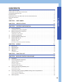
CONTENTS
SAFETY PRECAUTIONS . . . . . . . . . . . . . . . . . . . . . . . . . . . . . . . . . . . . . . . . . . . . . . . . . . . . . . . . . . . . . . . . . . . .1
CONDITIONS OF USE FOR THE PRODUCT . . . . . . . . . . . . . . . . . . . . . . . . . . . . . . . . . . . . . . . . . . . . . . . . . . . .9
CONSIDERATIONS FOR USE . . . . . . . . . . . . . . . . . . . . . . . . . . . . . . . . . . . . . . . . . . . . . . . . . . . . . . . . . . . . . . . .9
INTRODUCTION . . . . . . . . . . . . . . . . . . . . . . . . . . . . . . . . . . . . . . . . . . . . . . . . . . . . . . . . . . . . . . . . . . . . . . . . . .10
COMPLIANCE WITH THE EMC AND LOW VOLTAGE DIRECTIVES . . . . . . . . . . . . . . . . . . . . . . . . . . . . . . . . .10
TERMS . . . . . . . . . . . . . . . . . . . . . . . . . . . . . . . . . . . . . . . . . . . . . . . . . . . . . . . . . . . . . . . . . . . . . . . . . . . . . . . . .14
CHAPTER 1
PART NAMES
15
CHAPTER 2
SPECIFICATIONS
18
CHAPTER 3
SYSTEM CONFIGURATION
20
3.1
Overall Configuration . . . . . . . . . . . . . . . . . . . . . . . . . . . . . . . . . . . . . . . . . . . . . . . . . . . . . . . . . . . . . . . . . . . . 20
3.2
Multiple CPU System Configuration . . . . . . . . . . . . . . . . . . . . . . . . . . . . . . . . . . . . . . . . . . . . . . . . . . . . . . . . 23
CONTENTS
RELEVANT MANUALS . . . . . . . . . . . . . . . . . . . . . . . . . . . . . . . . . . . . . . . . . . . . . . . . . . . . . . . . . . . . . . . . . . . . .13
Considerations for system configuration . . . . . . . . . . . . . . . . . . . . . . . . . . . . . . . . . . . . . . . . . . . . . . . . . . . . . . . 21
Supported CPU module. . . . . . . . . . . . . . . . . . . . . . . . . . . . . . . . . . . . . . . . . . . . . . . . . . . . . . . . . . . . . . . . . . . . 23
Combination of CPU module . . . . . . . . . . . . . . . . . . . . . . . . . . . . . . . . . . . . . . . . . . . . . . . . . . . . . . . . . . . . . . . . 23
3.3
Peripheral Configuration . . . . . . . . . . . . . . . . . . . . . . . . . . . . . . . . . . . . . . . . . . . . . . . . . . . . . . . . . . . . . . . . . 24
3.4
Supported Software Package List . . . . . . . . . . . . . . . . . . . . . . . . . . . . . . . . . . . . . . . . . . . . . . . . . . . . . . . . . . 25
3.5
Supported Module List . . . . . . . . . . . . . . . . . . . . . . . . . . . . . . . . . . . . . . . . . . . . . . . . . . . . . . . . . . . . . . . . . . . 26
MELSEC iQ-R series. . . . . . . . . . . . . . . . . . . . . . . . . . . . . . . . . . . . . . . . . . . . . . . . . . . . . . . . . . . . . . . . . . . . . . 26
MELSEC-Q series . . . . . . . . . . . . . . . . . . . . . . . . . . . . . . . . . . . . . . . . . . . . . . . . . . . . . . . . . . . . . . . . . . . . . . . . 28
SD memory card (need to purchase separately). . . . . . . . . . . . . . . . . . . . . . . . . . . . . . . . . . . . . . . . . . . . . . . . . 30
CHAPTER 4
WIRING
31
4.1
Ethernet Port . . . . . . . . . . . . . . . . . . . . . . . . . . . . . . . . . . . . . . . . . . . . . . . . . . . . . . . . . . . . . . . . . . . . . . . . . . . 31
4.2
RS-232 Interface . . . . . . . . . . . . . . . . . . . . . . . . . . . . . . . . . . . . . . . . . . . . . . . . . . . . . . . . . . . . . . . . . . . . . . . . 33
4.3
USB Connector . . . . . . . . . . . . . . . . . . . . . . . . . . . . . . . . . . . . . . . . . . . . . . . . . . . . . . . . . . . . . . . . . . . . . . . . . 34
4.4
HMI (GOT). . . . . . . . . . . . . . . . . . . . . . . . . . . . . . . . . . . . . . . . . . . . . . . . . . . . . . . . . . . . . . . . . . . . . . . . . . . . . . 34
Connection route . . . . . . . . . . . . . . . . . . . . . . . . . . . . . . . . . . . . . . . . . . . . . . . . . . . . . . . . . . . . . . . . . . . . . . . . . 34
CHAPTER 5
FUNCTION LIST
35
CHAPTER 6
MODULE STARTUP PROCEDURE
37
6.1
Initialization . . . . . . . . . . . . . . . . . . . . . . . . . . . . . . . . . . . . . . . . . . . . . . . . . . . . . . . . . . . . . . . . . . . . . . . . . . . . 39
6.2
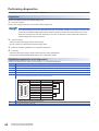
Performing Hardware Diagnostics . . . . . . . . . . . . . . . . . . . . . . . . . . . . . . . . . . . . . . . . . . . . . . . . . . . . . . . . . 41
Hardware diagnostics timing . . . . . . . . . . . . . . . . . . . . . . . . . . . . . . . . . . . . . . . . . . . . . . . . . . . . . . . . . . . . . . . . 41
Diagnostics types . . . . . . . . . . . . . . . . . . . . . . . . . . . . . . . . . . . . . . . . . . . . . . . . . . . . . . . . . . . . . . . . . . . . . . . . 41
Performing diagnostics . . . . . . . . . . . . . . . . . . . . . . . . . . . . . . . . . . . . . . . . . . . . . . . . . . . . . . . . . . . . . . . . . . . . 42
Operation at error detection. . . . . . . . . . . . . . . . . . . . . . . . . . . . . . . . . . . . . . . . . . . . . . . . . . . . . . . . . . . . . . . . . 45
6.3
Inserting and Removing SD Memory Card . . . . . . . . . . . . . . . . . . . . . . . . . . . . . . . . . . . . . . . . . . . . . . . . . . . 46
How to insert a card. . . . . . . . . . . . . . . . . . . . . . . . . . . . . . . . . . . . . . . . . . . . . . . . . . . . . . . . . . . . . . . . . . . . . . . 46
How to remove a card . . . . . . . . . . . . . . . . . . . . . . . . . . . . . . . . . . . . . . . . . . . . . . . . . . . . . . . . . . . . . . . . . . . . . 46
6.4
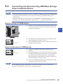
Connecting and disconnecting USB Mass Storage Class-compliant Device . . . . . . . . . . . . . . . . . . . . . . . 47
How to connect a USB device . . . . . . . . . . . . . . . . . . . . . . . . . . . . . . . . . . . . . . . . . . . . . . . . . . . . . . . . . . . . . . . 47
How to disconnect a USB device . . . . . . . . . . . . . . . . . . . . . . . . . . . . . . . . . . . . . . . . . . . . . . . . . . . . . . . . . . . . 47
6.5
Switch Operation . . . . . . . . . . . . . . . . . . . . . . . . . . . . . . . . . . . . . . . . . . . . . . . . . . . . . . . . . . . . . . . . . . . . . . . . 48
11
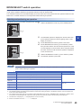
RESET/STOP/RUN switch . . . . . . . . . . . . . . . . . . . . . . . . . . . . . . . . . . . . . . . . . . . . . . . . . . . . . . . . . . . . . . . . . 48
MODE/SELECT switch operation . . . . . . . . . . . . . . . . . . . . . . . . . . . . . . . . . . . . . . . . . . . . . . . . . . . . . . . . . . . . 49
6.6
Creating Project. . . . . . . . . . . . . . . . . . . . . . . . . . . . . . . . . . . . . . . . . . . . . . . . . . . . . . . . . . . . . . . . . . . . . . . . . 51
6.7
Connecting to Personal Computer . . . . . . . . . . . . . . . . . . . . . . . . . . . . . . . . . . . . . . . . . . . . . . . . . . . . . . . . . 51
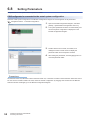
6.8
Setting Parameters . . . . . . . . . . . . . . . . . . . . . . . . . . . . . . . . . . . . . . . . . . . . . . . . . . . . . . . . . . . . . . . . . . . . . . 52
6.9
Writing Parameters to C Controller module . . . . . . . . . . . . . . . . . . . . . . . . . . . . . . . . . . . . . . . . . . . . . . . . . . 54
6.10
Creating User Program . . . . . . . . . . . . . . . . . . . . . . . . . . . . . . . . . . . . . . . . . . . . . . . . . . . . . . . . . . . . . . . . . . . 55
Considerations for programming . . . . . . . . . . . . . . . . . . . . . . . . . . . . . . . . . . . . . . . . . . . . . . . . . . . . . . . . . . . . . 55
6.11
Checking VxWorks Image File . . . . . . . . . . . . . . . . . . . . . . . . . . . . . . . . . . . . . . . . . . . . . . . . . . . . . . . . . . . . . 58
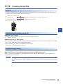
6.12
Creating Script File . . . . . . . . . . . . . . . . . . . . . . . . . . . . . . . . . . . . . . . . . . . . . . . . . . . . . . . . . . . . . . . . . . . . . . 59
6.13
Registering User Program . . . . . . . . . . . . . . . . . . . . . . . . . . . . . . . . . . . . . . . . . . . . . . . . . . . . . . . . . . . . . . . . 61
File writing method . . . . . . . . . . . . . . . . . . . . . . . . . . . . . . . . . . . . . . . . . . . . . . . . . . . . . . . . . . . . . . . . . . . . . . . 61
6.14
Troubleshooting . . . . . . . . . . . . . . . . . . . . . . . . . . . . . . . . . . . . . . . . . . . . . . . . . . . . . . . . . . . . . . . . . . . . . . . . 63
Troubleshooting procedure . . . . . . . . . . . . . . . . . . . . . . . . . . . . . . . . . . . . . . . . . . . . . . . . . . . . . . . . . . . . . . . . . 63
Checking with CW Configurator . . . . . . . . . . . . . . . . . . . . . . . . . . . . . . . . . . . . . . . . . . . . . . . . . . . . . . . . . . . . . 64
CHAPTER 7
MAINTENANCE AND INSPECTION
67
7.1
Daily Inspection . . . . . . . . . . . . . . . . . . . . . . . . . . . . . . . . . . . . . . . . . . . . . . . . . . . . . . . . . . . . . . . . . . . . . . . . . 67
7.2
Periodic Inspection . . . . . . . . . . . . . . . . . . . . . . . . . . . . . . . . . . . . . . . . . . . . . . . . . . . . . . . . . . . . . . . . . . . . . . 68
APPENDIX
69
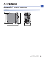
Appendix 1 External Dimensions . . . . . . . . . . . . . . . . . . . . . . . . . . . . . . . . . . . . . . . . . . . . . . . . . . . . . . . . . . . . . . . . 69
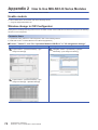
Appendix 2 How to Use MELSEC-Q Series Modules . . . . . . . . . . . . . . . . . . . . . . . . . . . . . . . . . . . . . . . . . . . . . . . . 70
Usable module. . . . . . . . . . . . . . . . . . . . . . . . . . . . . . . . . . . . . . . . . . . . . . . . . . . . . . . . . . . . . . . . . . . . . . . . . . . 70
Window change in CW Configurator . . . . . . . . . . . . . . . . . . . . . . . . . . . . . . . . . . . . . . . . . . . . . . . . . . . . . . . . . . 70
Setting procedure . . . . . . . . . . . . . . . . . . . . . . . . . . . . . . . . . . . . . . . . . . . . . . . . . . . . . . . . . . . . . . . . . . . . . . . . 73
Considerations. . . . . . . . . . . . . . . . . . . . . . . . . . . . . . . . . . . . . . . . . . . . . . . . . . . . . . . . . . . . . . . . . . . . . . . . . . . 74
Appendix 3 Handling of Batteries. . . . . . . . . . . . . . . . . . . . . . . . . . . . . . . . . . . . . . . . . . . . . . . . . . . . . . . . . . . . . . . . 76
Transport guidelines . . . . . . . . . . . . . . . . . . . . . . . . . . . . . . . . . . . . . . . . . . . . . . . . . . . . . . . . . . . . . . . . . . . . . . 76
Handling of batteries and devices with built-in batteries in EU member states . . . . . . . . . . . . . . . . . . . . . . . . . . 76
Disposal of batteries . . . . . . . . . . . . . . . . . . . . . . . . . . . . . . . . . . . . . . . . . . . . . . . . . . . . . . . . . . . . . . . . . . . . . . 76
INDEX
78
REVISIONS . . . . . . . . . . . . . . . . . . . . . . . . . . . . . . . . . . . . . . . . . . . . . . . . . . . . . . . . . . . . . . . . . . . . . . . . . . . . . .80
WARRANTY . . . . . . . . . . . . . . . . . . . . . . . . . . . . . . . . . . . . . . . . . . . . . . . . . . . . . . . . . . . . . . . . . . . . . . . . . . . . .81
TRADEMARKS . . . . . . . . . . . . . . . . . . . . . . . . . . . . . . . . . . . . . . . . . . . . . . . . . . . . . . . . . . . . . . . . . . . . . . . . . . .82
12
RELEVANT MANUALS
Manual name [manual number]
Description
Available form
MELSEC iQ-R C Controller Module User's Manual
(Startup)
[SH-081367ENG] (this manual)
Explains the performance specifications, module startup
procedure, and troubleshooting of C Controller module.
Print book
e-Manual
EPUB
PDF
MELSEC iQ-R C Controller Module User's Manual
(Application)
[SH-081369ENG]
Explains the functions, devices, and parameters of C Controller
module.
Print book
e-Manual
EPUB
PDF
MELSEC iQ-R C Controller Module Programming Manual
[SH-081371ENG]
Explains the programming specifications and dedicated
functions of C Controller module.
e-Manual
EPUB
PDF
CW Workbench/CW-Sim Operating Manual
[SH-081373ENG]
Explains the system configuration, specifications, functions,
and troubleshooting of CW Workbench/CW-Sim.
e-Manual
EPUB
PDF
CW Configurator Operating Manual
[SH-081382ENG]
Explains the system configuration, parameter settings, and
operation methods for the online function of CW Configurator.
e-Manual
EPUB
PDF
This manual does not include detailed information on the following:
• General specifications
• The number of mountable modules
• Installation environment and mounted position of the module
For details, refer to the following manual.
MELSEC iQ-R Module Configuration Manual
Note that the following terms in the left column shall be replaced with the one in the right column.
Term
Replaced term
Programmable controller
C Controller module
Programmable controller system
C Controller system
• Dedicated function library (C Controller module dedicated functions, MELSEC data link functions)
For details, refer to the following manual.
MELSEC iQ-R C Controller Module Programming Manual
e-Manual refers to the Mitsubishi FA electronic book manuals that can be browsed using a dedicated tool.
e-Manual has the following features:
• Required information can be cross-searched in multiple manuals.
• Other manuals can be accessed from the links in the manual.
• The hardware specifications of each part can be found from the product figures.
• Pages that users often browse can be bookmarked.
13
TERMS
Unless otherwise specified, this manual uses the following terms.
Term
14
Description
Base unit
A generic term for the main base unit, extension base unit, and RQ extension base unit
C Controller module
A generic term for MELSEC iQ-R series C Controller module
C Controller module dedicated function
A dedicated function library offered by C Controller module
It controls C Controller module.
CPU module
A generic term for MELSEC iQ-R series CPU module
CW Configurator
A generic product name for model names, SWnDND-RCCPU ('n' indicates version.)
CW Workbench
An abbreviation for Engineering tool for C Controller module, CW Workbench
CW-Sim
An abbreviation for VxWorks simulator that can operate and debug the C Controller module programs on a
personal computer with CW Workbench installed, without connecting to the actual machine (target)
Dedicated function library
A generic term for C Controller module dedicated functions and MELSEC data link functions
GOT
An abbreviation for the Mitsubishi Graphic Operation Terminal
I/O module
A generic term for input module, output module, I/O combined module, and interrupt module
Intelligent function module
A generic term for modules which has functions other than input and output, such as A/D converter module and
D/A converter module
MELSEC data link function
A dedicated function library offered by C Controller module
It is used to access other CPU modules as a connection target via network or in a multiple CPU system.
Network module
A generic term for the following modules:
• CC-Link module
• CC-Link IE Controller Network module
• CC-Link IE Field Network module
Power supply module
A generic term for MELSEC iQ-R series power supply module
R12CCPU-V
An abbreviation for R12CCPU-V C Controller module
SD memory card
A memory card that is compliant with the SD standards designed and developed by the SD Association
Target device
A generic term for a personal computer, GOT, other CPU modules, and others connected to CPU module for
data communication
USB Mass Storage Class-compliant device
A USB device that is compliant with the standard for recognizing as a memory device (USB Mass Storage Class)
VxWorks
A product name for the real-time operating system manufactured by Wind River Systems, Inc.
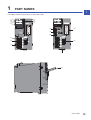
1
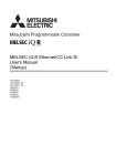
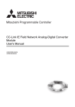
PART NAMES
1
This chapter explains the part names of C Controller module.
(1)
(3)
(5)
(2)
(4)
(6)
(7)
(8)
(15)
(12)
(16)
(17)
(9)
(13)
(10)
(11)
(14)
(18)
1 PART NAMES
15
16
No.
Name
Description
(1)
READY LED
Indicates the operation mode.
ON: Normal operation mode
Flashing (low-speed): Initial processing (Executing the script file, "STARTUP.CMD")
OFF (for normal operation): Hardware failure occurred or resetting
OFF (for diagnostic mode): Hardware diagnostic mode
(2)
ERROR LED
Indicates the error status.
ON: A continuation error occurred or a major error occurred
Flashing (for normal operation): A stop error occurred
Flashing (for diagnostic mode): A hardware diagnostic error or initialization error occurred
OFF: Normal operation
(3)
BUS RUN LED
Indicates the operating status.
ON (for normal operation): RUN state (State where output (Y) from a user program and writing to the buffer
memory are permitted)
ON (for diagnostic mode): Hardware diagnostic mode
Flashing (low-speed): Performing the hardware diagnostics, configuring the module initialization setting, or
performing initialization
Flashing (high-speed): Program/data memory shutdown completed status
OFF : STOP/PAUSE state (State where output (Y) from a user program and writing to the buffer memory are
prohibited)
(4)
CARD RDY LED
Indicates the availability of SD memory card.
ON: Accessible status (Mounted status)
Flashing: Mount processing or unmount processing
OFF: Inaccessible status (Not inserted or unmounted status)
(5)
USER LED
The indication can be controlled with a user program.
(6)
USB RDY LED
Indicates the availability of USB Mass Storage Class-compliant device.
ON: Accessible status (Mounted status)
Flashing: Mount processing or unmount processing
OFF: Inaccessible status (Not installed or unmounted status)
(7)
RS SD/RD LED
Indicates data transmission/reception status of the RS-232 interface.
ON: Transmitting/receiving data
OFF: Not transmitting/receiving data
(8)
Dot matrix LED
Displays the settings or results for the operation selection mode or hardware diagnostic mode.
The display can be controlled with a user program during the normal operation.
(9)
SPEED LED
Indicates the communication speed and link status for Ethernet.
ON (orange): Linking-up (1000 Mbps)
ON (green): Linking-up (100 Mbps)
OFF: Linking-down or linking-up (10 Mbps)
(10)
SD/RD LED
Indicates data transmission/reception status with Ethernet.
ON: Transmitting/receiving data
OFF: Not transmitting/receiving data
(11)
Ethernet port
Port for connecting with Ethernet-supported devices
(12)
RS-232 connector
Connector for connecting with RS-232 supported devices
(13)
USB connector
Connector for connecting with USB-supported devices
(14)
Product information marking
Displays the production information (16 digits) of the module.
(15)
RESET/STOP/RUN switch*1
A switch to operate the hardware operating status
RUN: Changes the operating status of the module to RUN. (Status where output (Y) from a user program and
writing to the buffer memory are permitted)
STOP: Changes the operating status of the module to STOP. (Status where output (Y) from a user program and
writing to the buffer memory are prohibited)
RESET: Resets the module.
The switch operation for each operating status is shown below.
For initialization
Page 39 Initialization
For hardware diagnostics
Page 41 Performing Hardware Diagnostics
For operation selection mode
Page 48 Switch Operation
(16)
MODE/SELECT switch*1
A switch to select the hardware mode
The switch operation for each operating status is shown below.
For initialization
Page 39 Initialization
For hardware diagnostics
Page 41 Performing Hardware Diagnostics
For operation selection mode
Page 48 Switch Operation
1 PART NAMES
No.
Name
(17)
SD memory card slot
A slot to insert an SD memory card
(18)
Slot cover*2
A cover for the SD memory card slot and switches
Open this cover to insert/remove an SD memory card or to operate the switches.
*1
*2
Description
1
Operate the switches by fingertip. Using tools such as a screwdriver may cause damage on the switches.
Close the cover unless inserting/removing an SD memory card or operating the switches to prevent foreign material intrusion such as
dust.
1 PART NAMES
17
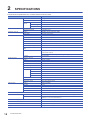
2
SPECIFICATIONS
The performance specifications of C Controller module are shown below.
Item
Hardware
R12CCPU-V
Endian format
Little endian
MPU
ARM Cortex-A9 Dual Core
Memory
capacity
Software
Work RAM
256 MB
ROM
12 MB
Backup RAM*1
4 MB
Operating system
VxWorks Version 6.9
Programming language
C language (C/C++)
SD memory card slot
Interface
SD/SDHC memory card (Up to 16 GB)
Power supply
+3.3 VDC, up to 200 mA
Ethernet port
Number of channels
2
Interface
10BASE-T/100BASE-TX/1000BASE-T
Communication method
Full-duplex/half-duplex
Data transmission speed
10 Mbps(10BASE-T)/100 Mbps(100BASE-TX)/1000 Mbps(1000BASE-T)
Transmission method
Base band
Maximum segment length
100 m (distance between hub and node)
Applicable connector for external
wiring
RJ45
Supported function
Auto-negotiation function (automatic recognition of communication speed/
communication method)
Auto-MDI/MDIX (automatic recognition of straight/crossing cable)
IP version
RS-232 connector
USB connector
IPv4 supported
Number of channels
1
Interface
RS-232-compliant
Communication method
Full-duplex/half-duplex
Synchronization method
Asynchronous communication
Transmission speed
9600, 14400, 19200, 28800, 38400, 57600, 115200 bps
Transmission distance
Up to 15 m
Data format
Start bit
1
Data bit
7/8
Parity bit
1/None
Stop bit
1/2
Parity check
Yes (Even/Odd)/None
Sum check code
Yes/None
Transmission control
Flow control (RS/CS control)
Interface
USB 2.0-compliant
Connector
Type A
Transfer speed
480 Mbps (High Speed)
Power supply
Bus power +5 VDC, up to 500 mA*2
Complied standard
Number of input/output points
Clock function
18
USB Mass Storage Class (Up to 2 TB)
4096 points (X/Y0 to FFF)
Displayed information
Year, month, day, hour, minute, second, day of week (automatic leap year detection)
Precision
Daily error : -5.86 to +3.35 seconds (0 to 55 )
Daily error: -1.71 to +3.35 seconds (25 )
Allowable momentary power failure time
Depends on the Power supply module.
5 VDC internal current consumption
1.26 A*3
External dimensions
106 (H) 56 (W) 110 (D) mm
Weight
0.35 kg
2 SPECIFICATIONS
*1
*2
*3
A file storage area in the device/label memory. For details on the memory configuration, refer to the following manual.
MELSEC iQ-R C Controller Module User's Manual (Application)
Select appropriate USB Mass Storage Class-compliant devices to be connected to observe the current consumption limit.
The current consumption of USB is not included.
2
2 SPECIFICATIONS
19
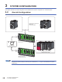
3
SYSTEM CONFIGURATION
This chapter describes the overall configuration and considerations for system configuration of C Controller system.
3.1
Overall Configuration
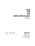
The overall configuration of C Controller system is shown below.
· Programmable controller CPU
· Motion CPU
· C Controller module
· C Controller module
· Main base unit
Extension cable
Power supply module / I/O module /
Intelligent function module
· Extension base unit
· RQ extension base unit
Configure the system properly by observing the considerations. (Page 21 Considerations for system
configuration)
20
3 SYSTEM CONFIGURATION
3.1 Overall Configuration
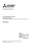
Considerations for system configuration
The following describes the considerations for configuring the system.
System configuration specification
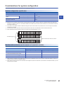
Item
Description
Mounting position of a module
Maximum number of mountable
modules
Slot number 1 to 63
Single CPU system configuration
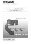
63*1,*3
Multiple CPU system configuration
57 to 62*1,*2,*3
Maximum number of extension base units
7*4
Total extension cable length
20 m*5
*1
*2
*3
*4
*5
3
Mount modules within the range of the number of I/O points for the C Controller module used. (Page 18 SPECIFICATIONS)
Modules can be mounted up to slot number 63 starting from the slot next to the one on which C Controller module at the right end is
mounted. For example, when four C Controller modules are mounted on the CPU slot and slot number 0 to 6, the maximum number of
mountable modules is 57.
The number of mountable modules includes the empty slots. Even if the number of I/O points is set to '0' for an empty slot, the slot is
counted as one module.
This is the total number of extension base units, RQ extension base units, and MELSEC-Q series extension base units.
When a MELSEC-Q series module is used in the system, the total cable length is 13.2 m.
CPU
0
1
2
3
4
5
6
7
8
9
10 11
12
13
14
15
16
17
18
19
20
21
22
23
Total cable length: 20 m
Seven extension base units at a maximum
60
61
62
63
Modules with restrictions on the number of mountable modules
The modules which have the restriction on the number of mountable modules are shown below.
Item
Maximum number of mountable modules
Single CPU system configuration
Multiple CPU system configuration
• CC-Link IE Controller Network module
8
32
• CC-Link IE Field Network module
• CC-Link IE built-in Ethernet interface module
8*1
32*1
• CC-Link module
8
32*1
• Interrupt module (MELSEC-Q series)*2
1
4
*1
*2
When selecting a module of which setting is configured with the dedicated instruction from Module Configuration Diagram, there is no
restriction on the number of mountable modules.
When setting an interrupt pointer to be used with CW Configurator, there is no restriction on the number of mountable modules. Up to 64
modules can be mounted.
3 SYSTEM CONFIGURATION
3.1 Overall Configuration
21
Consideration for internal current consumption
Consider the system to be used so that the internal current consumption of the entire system is less than the rated output
current of Power supply module.
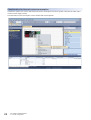
The total internal current consumption can be checked with CW Configurator.
22
3 SYSTEM CONFIGURATION
3.1 Overall Configuration
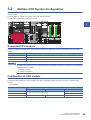
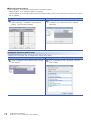
3.2
Multiple CPU System Configuration
In this configuration, multiple CPU modules are mounted, and individual CPU module controls I/O module and Intelligent
function module.
For more details on multiple CPU system, refer to the following manual.
MELSEC iQ-R Module Configuration Manual
3
Supported CPU module
Following are the CPU modules which can be used to configure a multiple CPU system in combination with C Controller
module.
CPU module
Model
Programmable controller CPU
R04CPU, R08CPU, R16CPU, R32CPU, R120CPU
Motion CPU
R16MTCPU, R32MTCPU
C Controller module
R12CCPU-V
A multiple CPU system cannot be configured when programmable controller CPU controls any of the following
Intelligent function modules:
• RJ71EN71 (CCIEC)
• RJ71EN71 (E+CCIEC)
Combination of CPU module
Combination in a multiple CPU system is as follows.
For details on the combination of CPU modules other than C Controller module, refer to the manual for respective CPU
modules.
: Not available
CPU No.1
Number of mountable CPU modules for CPU No.2 and later
Programmable controller CPU
Programmable controller CPU
Motion CPU
C Controller module
Motion CPU
C Controller module
MELSEC iQ-R Module Configuration Manual
User's manual for relevant CPU modules
0 to 3
0 to 3
0 to 3
0 to 3
3 SYSTEM CONFIGURATION
3.2 Multiple CPU System Configuration
23
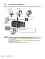
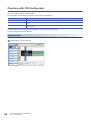
3.3
Peripheral Configuration
The configuration with peripherals is shown below.
Personal computer for maintenance
· Telnet function
· FTP function
User program development environment
· CW Workbench
· CW-Sim
SNTP server
SD memory card
USB device
· USB Mass Storage
Class-compliant device
Various networks via Network modules
· CC-Link IE Controller Network
· CC-Link IE Field Network
· CC-Link
HMI (GOT)
CW Configurator
• USB devices can be used for C Controller module with the firmware version '03' or later.
• Insert or connect peripherals to C Controller module so that the specifications of both C Controller module
and peripherals are met.
• For information on the access via each Network module and the access using Ethernet communication,
refer to the following manual.
MELSEC iQ-R C Controller Module User's Manual (Application)
24
3 SYSTEM CONFIGURATION
3.3 Peripheral Configuration
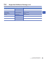
3.4
Supported Software Package List
This section describes all software packages associated with C Controller module.
Software package
CW Configurator
Version
SW1DND-RCCPU-J
Version 1.00A or later
SW1DND-RCCPU-E
CW Workbench
SW1DND-CWWR-E/EZ/EVZ
Version 1.00A or later
CW-Sim
SW1DND-CWWSIMR-EZ
Version 1.00A or later
CW-Sim Standalone
SW1DND-CWWSIMSAR-E
Version 1.00A or later
Wind River Workbench
Version 3.3
SW1DND-GXW3-J
Version 1.007H or later
GX Works3
3
SW1DND-GXW3-E
GT Designer3
SW1DNC-GTWK3-J
Version 1.126G or later
SW1DNC-GTWK3-E
MT Works2
SW1DNC-MTW2-J
Version 1.110Q or later
SW1DNC-MTW2-E
3 SYSTEM CONFIGURATION
3.4 Supported Software Package List
25
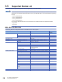
3.5
Supported Module List
This section shows the system configuration devices supported by C Controller module.
For the dedicated instructions of respective modules, which can be executed by C Controller module, refer to
the following C Controller module dedicated functions. ( MELSEC iQ-R C Controller Module Programming
Manual)
• CCPU_DedicatedDInst
• CCPU_DedicatedGInst
• CCPU_DedicatedJInst
• CCPU_DedicatedMInst
The following dedicated instruction can be executed to C Controller module from respective modules.
• D(P).GINT
• M(P).GINT
MELSEC iQ-R series
The following table lists configuration devices in the MELSEC iQ-R series system.
Module
Model
Main base unit
R35B, R38B, R312B
Extension base unit
R65B, R68B, R612B
RQ extension base unit
RQ65B, RQ68B, RQ612B
Extension cable
RC06B, RC12B, RC30B, RC50B
Power supply module
R61P, R63P
Programmable controller CPU
R04CPU, R08CPU, R16CPU, R32CPU, R120CPU
Motion CPU
R16MTCPU, R32MTCPU
AC input module
RX10
DC input module
RX40C7, RX41C4, RX42C4
Contact output module
RY10R2
Transistor output module
RY40NT5P, RY41NT2P, RY42NT2P, RY40PT5P,
RY41PT1P, RY42PT1P
I/O combined module
RH42C4NT2P
Base unit
CPU module
I/O module
Intelligent function module
Analog-digital converter module
R60AD4, R60AD8-G, R60AD16-G, R60ADI8, R60ADV8
Digital-analog converter module
R60DA4, R60DA8-G, R60DA16-G, R60DAI8, R60DAV8
Simple Motion module
RD77MS2, RD77MS4, RD77MS8, RD77MS16
High-speed counter module
RD62P2, RD62D2, RD62P2E
Positioning module
RD75P2, RD75P4, RD75D2, RD75D4
CC-Link IE Field Network module
RJ71GF11-T2
CC-Link IE Controller Network module
RJ71GP21-SX
CC-Link module
RJ61BT11
CC-Link IE built-in Ethernet interface
module
RJ71EN71
Serial communication module
RJ71C24, RJ71C24-R2, RJ71C24-R4
Channel isolated RTD input module
R60RD8-G
Channel isolated thermocouple input
module
R60TD8-G
Temperature control module
R64TCTT, R64TCRT, R64TCTTW, R64TCRTW
RG60
Blank cover
26
Function
version
3 SYSTEM CONFIGURATION
3.5 Supported Module List
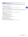
Restrictions
■CC-Link IE Field Network module
• The module cannot be used as a relay station for the data link transmission function or the routing function. To use either of
those functions, use a CC-Link IE Field Network master/local module controlled by a programmable controller CPU as a
relay station.
• An interrupt sequence program cannot be started.
• It cannot be used as a submaster station.
3
• The dynamic routing function cannot be used.
• The IP packet transfer function using the Ethernet port of C Controller module are not available.
■CC-Link IE Controller Network module
• The module cannot be used as a relay station for the interlink transmission function and the routing function. To use either
of those functions, use a CC-Link IE Controller Network module controlled by a programmable controller CPU as the relay
station.
• An interrupt sequence program cannot be started.
• The dynamic routing function cannot be used.
• The IP packet transfer function using the Ethernet port of C Controller module are not available.
■CC-Link module
• An interrupt sequence program cannot be started.
• The automatic CC-Link start function cannot be used.
• The standby master function cannot be used.
• The remote I/O net mode cannot be used.
• The master station duplex function cannot be used.
• The station-based block data assurance function cannot be used.
■Serial communication module
• Only the nonprocedural protocol can be used.
■CC-Link IE built-in Ethernet interface module
• Neither the Ethernet function nor the CC-Link IE Controller Network function can be used.
3 SYSTEM CONFIGURATION
3.5 Supported Module List
27
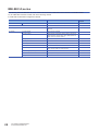
MELSEC-Q series
The following table lists MELSEC-Q series modules and extension cables that can be used for C Controller module.
To use a MELSEC-Q series module, refer to the following manual.
MELSEC iQ-R Module Configuration Manual
Module
Base unit
Function
version
Q52B, Q55B, Q63B, Q65B, Q68B, Q612B
Extension cable
QC05B, QC06B, QC12B, QC30B, QC50B, QC100B
Power supply module
Q61P, Q61P-A1, Q61P-A2, Q62P, Q63P, Q64P, Q64PN,
Q61P-D
I/O module
28
Extension base unit
Model
AC input module
QX10, QX10-TS, QX28
DC input module
QX40, QX40-TS, QX40-S1, QX41, QX41-S1, QX41-S2,
QX42, QX42-S1, QX70, QX71, QX72, QX80, QX80-TS,
QX81, QX81-S2, QX82, QX82-S1
DC high-speed input module
QX40H, QX70H, QX80H, QX90H
DC/AC input module
QX50
Contact output module
QY10, QY10-TS, QY18A
Triac output module
QY22
Transistor output module
QY40P, QY40P-TS, QY41P, QY42P, QY50, QY68A, QY70,
QY71, QY80, QY80-TS, QY81P, QY82P
Transistor high-speed output module
QY41H
I/O combined module
QH42P, QX48Y57, QX41Y41P
Interrupt module
QI60
3 SYSTEM CONFIGURATION
3.5 Supported Module List
Module
Intelligent function
module
Model
Function
version
Analog-digital converter module
Q64AD, Q68ADV, Q68ADI
Version B or later
Channel isolated high resolution analog-digital
converter module
Q64AD-GH
Channel isolated high resolution analog-digital
converter module (with signal conditioning
function)
Q62AD-DGH
Channel isolated analog-digital converter
module
Q68AD-G
Channel isolated analog-digital converter
module (with signal conditioning function)
Q66AD-DG
High speed analog-digital converter module
Q64ADH
Digital-analog converter module
Q62DAN, Q64DAN, Q68DAVN, Q68DAI, Q68DAIN
Q62DA, Q64DA, Q68DAV, Q68DAI
Version B or later
Channel isolated digital-analog converter
module
Q62DA-FG, Q66DA-G
High speed digital-analog converter module
Q64DAH
Analog input/output module
Q64AD2DA
Load cell input module
Q61LD
Current transformer input module
Q68CT
RTD input module
Q64RD
Channel isolated RTD input module
Q68RD3-G
Q64RD-G
Version B or later
Thermocouple input module
Q64TD
Channel isolated thermocouple/micro voltage
input module
Q64TDV-GH
Version B or later
Channel isolated thermocouple input module
Q68TD-G-H01, Q68TD-G-H02
Temperature control module
Q64TCTTN, Q64TCRTN, Q64TCTTBWN, Q64TCRTBWN
Loop control module
Q62HLC
High-speed counter module
QD64D2
Multichannel high-speed counter module
QD63P6
4Mpps capable high-speed counter module
QD64D2
Channel isolated pulse input module
QD60P8-G
Multi function counter/timer module
QD65PD2
Positioning module
QD70D4, QD70D8, QD73A1*1
QD70P4, QD70P8
Version B or later
Positioning module with built-in counter function
QD72P3C3
CC-Link/LT master module
QJ61CL12
Version B or later
AnyWire DB A20 master module
QJ51AW12D2
AnyWireASLINK master module
QJ51AW12AL
MODBUS/TCP interface module
QJ71MT91
MODBUS interface module
QJ71MB91
FL-net (OPCN-2) interface module
QJ71FL71-T, QJ71FL71-B5, QJ71FL71-F01, QJ71FL71B5-F01
QJ71FL71, QJ71FL71-B2, QJ71FL71-T-F01, QJ71FL71B2-F01
Version B or later
AS-i master module
QJ71AS92
Version B or later
Energy measuring module
QE81WH, QE84WH, QE81WH4W, QE83WH4W
QE82LG
QG60
Insulation monitoring module
Blank cover
*1
3
Use the module with a serial number of which first five digits are "16082" or later.
3 SYSTEM CONFIGURATION
3.5 Supported Module List
29
Restrictions
■FL-net (OPCN-2) interface module
• The word block read/write request messages using the message transmission function cannot be received.
• The auto refresh function cannot be used.
SD memory card (need to purchase separately)
One SD memory card can be inserted in C Controller module.
SD memory cards that can be used
Available Mitsubishi Electric Corporation's SD memory cards are as listed below:
Model
Description
NZ1MEM-2GBSD
SD memory card 2 GB
NZ1MEM-4GBSD
SD memory card 4 GB
NZ1MEM-8GBSD
SD memory card 8 GB
NZ1MEM-16GBSD
SD memory card 16 GB
For commercially available SD memory cards, refer to the following. Before using any commercially available SD memory
card, it is advised to check and ensure that the card has no impact on the control of the system.
TECHNICAL BULLETIN No. FA-A-0023
Precautions
• Use the format function of CW Configurator to format a SD memory card.
• If any SD memory card other than the one listed above is used, data in the SD memory card may be corrupted or a system
shutdown may occur.
• If C Controller module is powered OFF or reset, or the SD memory card is removed while the card is being accessed, data
in the SD memory card may be corrupted. Always power OFF or reset C Controller module, or remove the SD memory card
after the access to the card has been stopped.
30
3 SYSTEM CONFIGURATION
3.5 Supported Module List
4
WIRING
This chapter explains the wiring methods to C Controller module.
The bend radius of the cable near the connector or port should be at least four times longer than the cable's
outside diameter.
4.1
Ethernet Port
4
This section explains the specification of usable Ethernet cable and its wiring.
Ethernet cable
The following shows the specifications of the cables that can be used for connection with peripherals by using the Ethernet
port (CH1 and CH2). Cables compliant with IEEE802.3 10BASE-T/100BASE-TX/1000BASE-T standards can be used.
Transmission speed
Unshielded twisted pair cable (UTP cable)
Shielded twisted pair cable (STP cable)
Straight cable
Crossing cable
1000 Mbps
Category 5e or higher
Category 5e
100 Mbps
Category 5 or higher
Category 5 or 5e
10 Mbps
Category 3 or higher
Category 3 to 5e
In a high-speed communication (100 Mbps/1000 Mbps) with 100BASE-TX/1000BASE-T connection, a
communication error may occur due to high frequency noise generated from a device other than C Controller
module depending on the installation environment. When configuring a network system, take the following
measures on C Controller module side to eliminate the influence of high frequency noise.
• Do not install the twisted pair cables together with the main circuit or power lines, or bring them close to
each other.
• Make sure to place the twisted pair cable in a duct.
• In the environment where the cable is susceptible to noise, use the shielded twisted pair cable (STP cable).
• In an environment where the system is susceptible to noise, include a retry processing in the user program.
• Change the target device to be connected to C Controller module to the one which communicates at 10
Mbps, and decrease the data transmission rate.
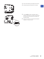
■Connecting procedure
1.
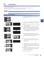
Insert the Ethernet cable into the C Controller module connector until it clicks with an attention to the orientation of the
connector.
2.
3.
Pull the cable slightly and check that it is connected properly.
Check the lighting status of the SPEED LED on the port to which the Ethernet cable is connected.
The time required from when the cable is connected to when the SPEED LED turns ON may vary. Normally,
the LED turns ON in a few seconds. However, it may take longer because the linking-up processing is
repeated due to the conditions of devices on the line. If the SPEED LED does not turn ON, check if the cable
has any failure.
■Disconnecting procedure
1.
Pull out the Ethernet cable while pinching the retaining clip of the connector.
4 WIRING
4.1 Ethernet Port
31
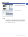
IP address setting
The IP address setting method is shown below.
■Setting IP address
To use the Ethernet port(s), set the IP address with CW Configurator.
[Module Parameter] "Own Node Settings" "IP Address"
Do not set the IP address for C Controller module with a user program. The network may be no longer
functional properly.
The default value is set to the IP address for C Controller module before shipment and after initialization.
Ethernet port
Default IP address
Ethernet port (CH1)
192.168.3.3
Ethernet port (CH2)
No setting
■Checking method of IP address
The IP address set to C Controller module can be checked with the operation selection mode.
For more details on the operation selection mode, refer to the following section.
Page 48 Switch Operation
Precautions
• Set the same value for the network portion of the IP addresses for the target device to be connected and the Ethernet port.
• Set the different value for the network portion of CH1 and CH2 on the Ethernet port.
• A message to the target device (including response packets such as ping) is sent (responded) from the Ethernet port that
has IP address of which network portion is the same.
Considerations for connection
Considerations for connection to Ethernet device are shown below.
• When the C Controller module has been replaced and also IP address has been changed, then reset the Ethernet device
too. If the Ethernet device holds the Ethernet address (MAC address) of the communication target, continuous
communication may not be performed since the module replacement and IP address change will change the Ethernet
address (MAC address).
• Perform the troubleshooting in accordance with the manual for the Ethernet device when an error occurred on the Ethernet
device.
• When Telnet or Shell of CW Workbench is connected to C Controller module, an event/error message may be displayed
once VxWorks detects a network error. For details on the displayed event/message, refer to the manual for VxWorks.
Please ask Wind River Systems, Inc. for any event/message which cannot be handled.
32
4 WIRING
4.1 Ethernet Port
4.2
RS-232 Interface
This section explains the specification of RS-232 interface and its wiring.
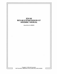
RS-232 connector
The RS-232 interface specifications to connect to a target device are shown below.
Connector shape
Pin No.
Signal
code
Signal name
1
CD(DCD)
Data carrier detect
2
RD(RXD)
Received data
3
SD(TXD)
Transmitted data
4
ER(DTR)
Data terminal ready
5
SG
Signal ground
6
DR(DSR)
Data set ready
7
RS(RTS)
Request to send
8
CS(CTS)
Clear to send
9
CI(RI)
Ring indicator
Signal direction (R12CCPU-V RS-232 device)
4
1
2
3
4
5
6
7
8
9
Use the following product as a connection cable connector.
Connector type
Manufacturer name
Model name
D-sub connector (Solder-connection type)
DDK Ltd.
17JE-13090-02(D8C)(-CG)
The specifications of fixing screws are as follows:
• Connector mating screw: #4-40UNC
• Tightening torque range : 0.15 to 0.20 Nm
• Make sure that RS-232 connection cable shield is single-point grounded.
• Do not short-circuit the FG and SG signals of the RS-232 connection cable. When the FG and SG signals
are connected inside of the peripheral device, do not connect the FG signal to C Controller module.
• For connection method of peripheral device, check the specifications of the peripheral device.
Considerations for connection
• A reception error may occur on the target device connected to C Controller module when the power supply for C Controller
module or the target device is turned ON or OFF.
• A reception error occurs on the target device when the system on the target device side is booting while C Controller
module is transmitting data to the target device.
• When an error occurred on the target device, take the corrective actions in accordance with the manual for the target
device.
4 WIRING
4.2 RS-232 Interface
33
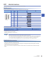
4.3
USB Connector
This section explains the specification of usable USB cable and its wiring.
USB cable
Use a USB cable supplied with the USB Mass Storage Class-compliant device.
The type of cable connector connectable with the USB connector is type A.
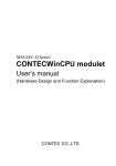
Preventing USB cable from falling out
Connected cable can be fixed to the hole for fixing band (1) of the module by using a fixing band (recommended specification:
width: 6 to 9 mm, thickness: 1 mm or less).
(1)
4.4
HMI (GOT)
This section explains the connection method of GOT to C Controller module.
Connection route
C Controller module can be connected to GOT by following route.
• Connection using Ethernet port
• Connection via Network module
Connection using Ethernet port
Connect to GOT by using the Ethernet port (CH1 and CH2).
Connection via Network module
Connection to GOT is available via following Network modules.
• CC-Link IE Controller Network connection
• CC-Link IE Field Network connection
• CC-Link connection (Via intelligent device station, G4)
For connection method via network, refer to the manual for Network module to be used.
34
4 WIRING
4.3 USB Connector
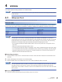
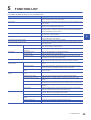
5
FUNCTION LIST
This chapter describes the functions of C Controller module.
Function
Description
Program monitoring function (WDT)
Monitors and detects hardware and user program errors using the watchdog timer,
which is the internal timer of C Controller module.
Clock function
Manages the time for the functions performed by the system such as date for the event
history function.
Remote operation function
Changes the operating status of C Controller module with CW Configurator or user
program, or by an external device using SLMP.
I/O module, Intelligent function module access function
Controls the I/O module and Intelligent function module(s), which are controlled by C
Controller module, by creating a user program using C Controller module dedicated
functions and MELSEC data link functions.
Interrupt function from module
Performs an interrupt routine by an interrupt request from input module, Intelligent
function module, or interrupt module.
Fixed cycle processing function
Performs refresh with a module such as Network module and performs data
communication with an external device.
Inter-module synchronization function
Performs synchronous control among each module.
Output mode setting of STOP to RUN
Sets the output (Y) mode when the operating status of C Controller module is switched
from STOP to RUN.
Memory card function
Boot operation
Transfers files stored in SD memory card to the CPU built-in memory when powering
OFF ON or resetting C Controller module.
Enable/disable the use of file/data on
memory card
Sets whether to use files/data stored on a memory card or not.
Self-diagnostic function
Diagnoses any abnormality by C Controller module itself.
RAS function
Error clear function
Clears a continuation error occurred in batch.
Event history function
Collects and saves the operation and error information of each module. The saved
event history can be viewed in chronological order.
Security function
Access function using
network module
Ethernet communication
function
Multiple CPU system function
5
Prevents from data pilferage, manipulation, misoperation, illegal execution due to an
illegal access to the program assets saved in a personal computer or modules.
Cyclic transmission
Performs data communication periodically between stations on a network using link
devices.
Transient transmission
Performs data communication with other station when the communication request is
issued. Communication with different network can also be performed.
Access function of each network
module
Transmits data to the devices on the network via a Network module controlled by C
Controller module.
Connection with MELSOFT product
or GOT
Monitors or tests C Controller module via Ethernet.
Communication with SLMP
Reads/writes device data from/to a personal computer or HMI using SLMP.
File transfer function (FTP server)
Handles the files in C Controller module from a target device with the FTP client
function.
Time setting function
Configures the time setting on C Controller module by collecting time information with
the specified timing from the time information server (SNTP server) connected to LAN.
Telnet function
Performs remote debugging of C Controller module with Telnet tool on a personal
computer.
Security function
Applies the optimal security according to the network environment by restricting the
access to C Controller module for each communication route.
Out-of-group I/O fetch
Accesses a module not controlled by CPU module to import the input/output (X/Y) or
access the buffer memory of Intelligent function module.
Operation setting
Configures operation settings for the multiple CPU system function.
Data communication between CPU
modules
Performs data communication among CPU modules of a multiple CPU system.
Interrupt from other CPU
Restarts the user program that is waiting for an interrupt event.
Issuing an interrupt to other CPU
Issues an interrupt to other CPU from the user program of C Controller module.
5 FUNCTION LIST
35
MEMO
36
5 FUNCTION LIST
6
MODULE STARTUP PROCEDURE
This chapter explains the startup procedure and program execution of C Controller module. Perform the hardware diagnostics
when the C Controller module is used for the very first time.
Performing hardware diagnostics
1.
Mount C Controller module.
Mount Power supply module and C Controller module on Base unit. ( MELSEC iQ-R Module Configuration Manual)
2.
Power ON the system.
Confirm the wiring and the supply voltage of the power supply before the system is powered ON.
3.
Initialize C controller module.
Initialize C Controller module. (Page 39 Initialization)
4.
Perform hardware diagnostics.
Check the hardware status of C Controller module. (Page 41 Performing Hardware Diagnostics)
6
Starting C Controller system
1.
Insert SD memory card.
Insert an SD memory card to C Controller module as necessary. (Page 46 Inserting and Removing SD Memory Card)
2.
Mount modules and wire for each device.
Mount respective modules on Base unit, and wire for each device. ( MELSEC iQ-R Module Configuration Manual)
3.
Power ON the system.
Check the following, and turn ON the power supply.
• The wiring and supply voltage of the power supply are in the required range.
• C Controller module is placed into the STOP state.
4.
Create a project.
Create a project for C Controller module to be used with a personal computer on which CW Configurator has been installed.
(Page 51 Creating Project)
5.
Connecting a personal computer to C Controller module
Connect the personal computer on which CW Configurator has been installed to C Controller module. (Page 51
Connecting to Personal Computer)
6.
Set parameters.
Set the system parameter, CPU parameter, and module parameter. (Page 52 Setting Parameters)
When using the SD memory card function, or when mounting Intelligent function module, also set parameters other than the
above. ( User's manual (Application) for each module)
7.
Write parameters to C Controller module.
Write the parameters set with CW Configurator to C Controller module. (Page 54 Writing Parameters to C Controller
module)
8.
Reset C Controller system.
Reset the system by one of the following methods.
• Turning ON OFF the power supply
• Resetting C Controller module (Page 48 Switch Operation)
6 MODULE STARTUP PROCEDURE
37
9.
Check errors.
Check the READY LED and ERROR LED on C Controller module. When any error occurred, perform the troubleshooting. In
case of any errors caused by factors other than C Controller module, refer to the manual for respective modules.
10. Create user programs.
Create a user program.
• Create a user program and debug it. (Page 55 Creating User Program)
• Create a script file. (Page 59 Creating Script File)
• Register the user program and the script file in C Controller module. (Page 61 Registering User Program)
11. Reset C Controller system.
Reset the system by one of the following methods.
• Turning ON OFF the power supply
• Resetting C Controller module (Page 48 Switch Operation)
12. Execute the program.
Change the operating status of the C Controller module to RUN state, and confirm the BUS RUN LED turns ON. (Page
48 Switch Operation)
38
6 MODULE STARTUP PROCEDURE
6.1
Initialization
Initialize C Controller module in the following cases.
• At the time of the first operation
• C Controller module does not start by execution of the script file registered in the program memory.
• The user name/password set to C Controller module has been forgotten.
The data in the program memory, device/label memory, and data memory is deleted during the process of
initialization. Back up all necessary data in advance.
Procedure for initialization
Confirm that the RESET/STOP/RUN switch is positioned at the center i.e. on the "Stop" position at first.
1. Put and hold the MODE/SELECT switch (1) on the
MODE position.
6
(1)
2.
Power ON C Controller module. The BUS RUN LED (2)
turns ON, and "M-00" is displayed on the dot matrix
LED.
(2)
3.
4.
Release the MODE/SELECT switch (1) and put it back
to the center position.
Set the MODE/SELECT switch (1) to the SELECT
position. Every time the switch is set to the SELECT
position, the value of mode displayed on the dot matrix
LED is changed. Repeat this switch movement until
(1)
"0011" is displayed on the dot matrix LED.
5.
Set the RESET/STOP/RUN switch (3) to the RUN
position. The selected mode is executed. The BUS RUN
LED (2) will be flashing during initialization.
(3)
(2)
6.
Confirm that the BUS RUN LED (2) turns ON and
"0000" is displayed on the dot matrix LED, and reset C
Controller module.
(2)
7.
The initialization is performed by resetting the module.
The READY LED (5) will turn ON, and the BUS RUN
LED (2) and USER LED (4) will be flashing during the
(5)
(2)
(4)
initialization.
8.
Upon normal completion of the initialization, the BUS
RUN LED (2) and USER LED (4) turns OFF, and the
READY LED (5) starts flashing.
(5)
9.
Reset C Controller module.
6 MODULE STARTUP PROCEDURE
6.1 Initialization
39
■Mode selection
Mode
Dot matrix LED display
Description
10
0010
Default IP setting
11
0011
Module initialization setting
■Abnormal completion of initialization process
Upon abnormal completion of the initialization, the ERROR LED will be flashing, and the READY LED and USER LED turn
ON. In the case of abnormal completion, perform the initialization again.
Do not reset the module during the initialization of C Controller module. Perform the initialization again if the
module has been reset in error.
Module status after initialization
After initialization, the status of C Controller module will be as follows:
■Default IP setting
• The registered script file stops to be executed.*1
• The IP address for C Controller module is set to the default. (Page 31 Ethernet Port)
*1
The script file name is renamed as "STARTUP.BAK", and deregistered.
■Module initialization setting
• Default parameters are set to the data memory.
• The program memory, device/label memory, and data memory are formatted.
• The security password is initialized. (Default password: password)
40
6 MODULE STARTUP PROCEDURE
6.1 Initialization
6.2
Performing Hardware Diagnostics
Diagnose the hardware of C Controller module.
Hardware diagnostics timing
The hardware diagnostics is used in the following cases.
• At the time of first operation
• For troubleshooting
Do not power OFF or reset C Controller module during the hardware diagnostics. Doing so may cause
abnormal startup of C Controller module. If it does not start normally, perform the initialization.
Diagnostics types
The mode of hardware diagnostics is shown below.
Mode
Dot matrix LED display
Diagnostic item
Description
0
M-00
Diagnostic test for Mode 1 to Mode 6
Performs the diagnostic test in the order from Mode 1 to Mode 6.
1
M-01
Program memory, data memory
diagnostic test
Reads data in the program memory and data memory, and
performs error detection.
Device/label memory diagnostic test
Writes/reads test data to/from the device/label memory, and
checks by verifying the data.
2
M-02
Ethernet diagnostic test
Diagnoses the Ethernet port (CH1 and CH2) status.
3
M-03
SD memory card interface diagnostic
test
Diagnoses the SD memory card slot status.
4
M-04
RS-232 diagnostic test
Conducts a self-loopback test of the RS-232 connector. The
wiring for self-loopback is required.
5
M-05
USB diagnostic test
Diagnoses the USB connector status.
6
M-06
Bus diagnostic test
Writes/reads/verifies the memory of the internal bus and register.
7
M-07
Dot matrix LED test
Shows the dot matrix LED test display.
6 MODULE STARTUP PROCEDURE
6.2 Performing Hardware Diagnostics
6
41
Performing diagnostics
The following shows the procedure for hardware diagnostics.
Preparation
Perform the following before the hardware diagnostics.
1.
Mount the modules.
Mount Power supply module and C Controller module on Base unit.
The hardware diagnostics can be performed even when C Controller module is not mounted on the CPU slot.
To perform the hardware diagnostics with the module mounted on the slot other than the CPU slot, mount
other CPU module on the CPU slot. Although an error may be detected on the mounted CPU module, the
hardware diagnostics can be performed.
2.
Check the wiring.
• Check that the power supply cable is wired properly.
• Do not connect any cable other than power supply cable.
3.
4.
Make the necessary preparations for respective diagnostics.
Power ON.
• Check that the power supply voltage is within the range of the specifications.
• Confirm that the RESET/STOP/RUN switch is put on the STOP position.
Preparation required for each diagnostics
Perform the following before starting each mode (0 to 7) of hardware diagnostics.
Mode
Description
0
Make all of the preparations required for Mode 1 to 6.
1
Back up the data in the program memory, data memory, and device/label memory.
2
Check that no cable is connected to the Ethernet port.
3
Check that no SD memory card is inserted.
4
Connect a cable to the RS-232 connector.
The connector pin arrangement and cable connection are shown below.
Connector
Pin No.
Signal code
1
CD(DCD)
1
2
3
4
5
42
6
7
2
RD(RXD)
3
SD(TXD)
4
ER(DTR)
5
SG
8
6
DR(DSR)
9
7
RS(RTS)
8
CS(CTS)
9
CI(RI)
5
Check that no cable is connected to the USB connector.
6
No preparation required for this mode.
6 MODULE STARTUP PROCEDURE
6.2 Performing Hardware Diagnostics
Cable connection
Mode selection
The following explains the procedure to select mode.
1.
2.
3.
4.
5.
6.
7.
Set the RESET/STOP/RUN switch to the RESET position, and keep it up to the step 4.
Check that all LEDs turned OFF.
Set the MODE/SELECT switch to the MODE position, and keep it up to the step 6.
Put the RESET/STOP/RUN switch back into the STOP position.
The BUS RUN LED turns ON, and "M-00" is displayed on the dot matrix LED.
Put the MODE/SELECT switch back to the center position.
Set the MODE/SELECT switch to the SELECT position, and select the desired diagnostic mode.
Every time the switch is set to the SELECT position, the value of mode displayed on the dot matrix LED is changed.
Repeat this switch movement until the dot matrix LED displays the desired diagnostic mode.
Mode execution
The following shows how to execute the selected mode.
6
■Executing Mode 0 to 6
1.
Set the RESET/STOP/RUN switch to the RUN position.
• While Mode 0 or 1 is being executed, the BUS RUN LED will be flashing, and the current mode and its progress are
displayed alternatively on the dot matrix LED.
(Example): "M-01" (diagnostic mode) displaying alternatively "0050" (progress: %)
• While Mode 2 to 6 is being executed, the BUS RUN LED will be flashing, and the current mode is displayed on the dot
matrix LED.
2.
Check that the BUS RUN LED turns ON.
When the test is completed normally, "0000" is displayed on the dot matrix LED.
3.
Turn the power supply OFF.
Before performing the steps of mode execution, put the RESET/STOP/RUN switch back to the STOP position,
if the switch is in the RUN position.
6 MODULE STARTUP PROCEDURE
6.2 Performing Hardware Diagnostics
43
■Executing Mode 7
1.
2.
Set the RESET/STOP/RUN switch to the RUN position.
Set the MODE/SELECT switch to the SELECT position.
Every time the switch is set to the SELECT position, the lighting status on the dot matrix LED switches.
ON
OFF
Pattern 1 (All LEDs ON)
Pattern 3 (1st row ON)
Pattern 2 (1st column ON)
Pattern 3 (2nd row ON)
Pattern 2 (2nd column ON)
Pattern 3 (3rd row ON)
Pattern 2 (3rd column ON)
Pattern 3 (4th row ON)
Pattern 2 (4th column ON)
Pattern 3 (5th row ON)
Pattern 2 (5th column ON)
Pattern 3 (6th row ON)
Pattern 3 (7th row ON)
3.
Turn the power supply OFF.
Visually inspect the dot matrix LED and confirm no inactive dot exists on the LED. If there is any inactive LED,
C Controller module may have its hardware failure. Please consult your local Mitsubishi representative.
44
6 MODULE STARTUP PROCEDURE
6.2 Performing Hardware Diagnostics
Operation at error detection
The error contents displayed at the time of error detection are shown below.
Dot matrix LED displays other than "0000"
The ERROR LED start flashing and the value corresponding to the diagnostics on which an error occurred will be displayed at
the time of error detection during diagnostics or setting. Only flashing of the ERROR LED without dot matrix LED display
means a system error.
Mode
Dot matrix LED display
Diagnostics on which an error occurred
1
E010
Program memory, data memory diagnostic test
Device/label memory diagnostic test
E020
E030
E040
2
E050
Ethernet diagnostic test (CH1)
E060
Ethernet diagnostic test (CH2)
3
E070
SD memory card interface diagnostic test
4
E080
RS-232 diagnostic test*1
5
E090
USB diagnostic test
6
E0A0
Bus diagnostic test
6
E0B0
E0C0
E0D0
E0E0
*1
An error may occur if a wiring cable is not connected properly. Connect the cable or wire the cable correctly again, and perform the
diagnostics for Mode 4.
The diagnostics or setting will be terminated at the time of abnormal completion. Retry the diagnostics or
setting. If an error is detected after the abnormal completion, C Controller module may have its hardware
failure. Please consult your local Mitsubishi representative.
6 MODULE STARTUP PROCEDURE
6.2 Performing Hardware Diagnostics
45
6.3
Inserting and Removing SD Memory Card
This section explains the method for inserting/removing an SD memory card.
• Follow the procedures shown below to insert or remove an SD memory card while the power is ON. Failure
to do so may cause data corruption in the SD memory card.
• Change the MODE/SELECT switch operation to "SD UNMOUNT" or "SD/USB UNMOUNT" before
removing the SD memory card. (Page 48 Switch Operation)
How to insert a card
Insert an SD memory card according to the following procedure with attention to its direction.
1. Insert an SD memory card (1) straight into the SD memory card slot
with its cutout pointed down. Make sure it is not uplifted after
(2)
inserting it.
2.
The CARD RDY LED (2) keeps flashing until the SD memory card is
ready to be used.
(1)
3.
Once the CARD RDY LED (2) turns ON, the card can be used.
1.
2.
Check that no SD memory card is accessed.
How to remove a card
(2)
Hold the MODE/SELECT switch in the SELECT position to unmount
the SD memory card. The CARD RDY LED (2) is flashing, which
indicates that process of unmounting SD card is in progress, and
later upon successful completion, the LED turns OFF.
(1)
3.
Push the SD memory card (1) in once, and pull it out straight.
The SD memory card can also be mounted or unmounted with a user program using C Controller module
dedicated functions (CCPU_MountMemoryCard, CCPU_UnmountMemoryCard).
Precautions
Do not perform the following operations while accessing the files in an SD memory card. Doing so may result in data
corruption in the SD memory card or file system error.
• Resetting C Controller module
• Powering ON OFF the system
• Unmounting the SD memory card
• Removing the SD memory card
46
6 MODULE STARTUP PROCEDURE
6.3 Inserting and Removing SD Memory Card
6.4
Connecting and disconnecting USB Mass Storage
Class-compliant Device
This section explains the method for connecting/disconnecting a USB Mass Storage Class-compliant device.
• Follow the procedures shown below to connect or disconnect a USB Mass Storage Class-compliant device
while the power is ON. Failure to do so may cause data corruption in the USB Mass Storage Classcompliant device.
• Change the MODE/SELECT switch operation to "USB UNMOUNT" or "SD/USB UNMOUNT" before
disconnecting the USB Mass Storage Class-compliant device. (Page 48 Switch Operation)
How to connect a USB device
1.
Connect a connector of USB Mass Storage Class-compliant device
or USB cable to the USB connector (1). Firmly insert the connector
to prevent it from falling out.
6
(1)
2.
The USB RDY LED (2) keeps flashing until the USB Mass Storage
Class-compliant device is ready to be used.
(2)
3.
Once the USB RDY LED (2) turns ON, the USB Mass Storage Classcompliant device can be used.
How to disconnect a USB device
1.
Check that no USB Mass Storage Class-compliant device is
accessed.
(2)
2.
Hold the MODE/SELECT switch in the SELECT position to unmount
the USB Mass Storage Class-compliant device. The USB RDY LED
(2) is flashing, which indicates that process of unmounting USB
Mass Storage Class-compliant device is in progress, and later upon
successful completion, the LED turns OFF.
3.
Disconnect the USB Mass Storage Class-compliant device or USB
cable that is inserted to the USB connector.
The USB Mass Storage Class-compliant device can also be unmounted with a user program using C
Controller module dedicated functions (CCPU_UnmountMemoryCard).
6 MODULE STARTUP PROCEDURE
6.4 Connecting and disconnecting USB Mass Storage Class-compliant Device
47
Precautions
Do not perform the following operations while accessing the files in a USB Mass Storage Class-compliant device. Doing so
may result in data corruption in the USB Mass Storage Class-compliant device or file system error.
• Resetting C Controller module
• Powering ON OFF the system
• Unmounting the USB Mass Storage Class-compliant device
• Disconnecting the USB Mass Storage Class-compliant device
6.5
Switch Operation
This section explains the method for changing the operating status of C Controller module.
RESET/STOP/RUN switch
The operating status of C Controller module can be changed using the RESET/STOP/RUN switch.
• By setting the switch to the RUN position, the operating status is changed to RUN. (Status where output (Y) from a user
program and writing to the buffer memory are permitted)
• By setting the switch to the STOP position, the operating status is changed to STOP. (Status where output (Y) from a user
program and writing to the buffer memory are prohibited)
• Operating the switch with the following procedure resets C Controller module.
1. Hold the RESET/STOP/RUN switch (1) in the RESET
position.
(2)
2.
Check that all LEDs turn OFF after the ERROR LED (2)
flashes several times.
3.
Put the RESET/STOP/RUN switch (1) back to the STOP
position.
(1)
Operate the RESET/STOP/RUN switch by fingertip. Using tools such as a screwdriver may cause damage on
the switch.
48
6 MODULE STARTUP PROCEDURE
6.5 Switch Operation
MODE/SELECT switch operation
With the MODE/SELECT switch, the mode can be switched between the operation selection mode and normal operation
mode, and the operation selected in the operation selection mode can be performed.
The 'notification/unmount' and 'information display on the dot matrix LED' can be performed in the operation selection mode.
Make sure C Controller module is in normal operation before selecting its operation.
Selecting and performing an operation
The following shows how to select and perform the operation.
1.
Hold the MODE/SELECT switch (1) in the MODE position.
2.
The selectable operation is displayed on the dot matrix LED.
(1)
6
(In the operation selection mode, the lighting status of LED
display is reversed.)
3.
4.
Put the MODE/SELECT switch (1) back to the center.
Set the MODE/SELECT switch (1) to the SELECT position.
Every time the switch is set to the SELECT position, the value
of mode displayed on the dot matrix LED is changed. Repeat
this switch movement until the desired operation is displayed
on the dot matrix LED.
(1)
5.
6.
Hold the MODE/SELECT switch (1) in the SELECT position.
The selected operation is performed.
The mode is switched to the normal operation mode by holding the MODE/SELECT switch in the MODE
position while selecting an operation.
LED display*1
Operation
Operation at execution
EVENT
Notifies an event to the user program. (Default)
Notification/unmount*2
SD UNMOUNT
Unmounts the SD memory card forcibly.
USB UNMOUNT
Unmounts the USB Mass Storage Class-compliant device forcibly.
SD/USB
UNMOUNT
Unmounts the SD memory card and USB Mass Storage Class-compliant device forcibly.
USER*3
Displays contents specified by the user on the dot matrix LED. (Default)
ERROR*4
Displays an error code on the dot matrix LED.
CH1*5
Displays IP address of the Ethernet port (CH1) on the dot matrix LED.
CH2
*5
Displays IP address of the Ethernet port (CH2) on the dot matrix LED.
*1
*2
The LED display scrolls horizontally (right left) to display the portion not appeared on dot matrix LED.
The selected operation is registered in the behavior caused when holding the switch in the SELECT position, and can be performed
even in the normal operation mode.
The character string output with the C Controller module dedicated function (CCPU_SetDotMatrixLED) is displayed. In addition, when
this operation is selected again after switched to other operation, the previously shown character string will be displayed.
The latest error is displayed. ("" is displayed when no error occurred.)
When the IP address is not set, "..." is displayed.
*3
*4
*5
Information display on the dot
matrix LED
6 MODULE STARTUP PROCEDURE
6.5 Switch Operation
49
■Performing the 'notification/unmount' in the normal operation mode
The last selected operation (out of 'notification/unmount') in the operation selection mode is registered as the operation
performable by holding the switch in the SELECT position. By holding the MODE/SELECT switch in the SELECT position, the
registered operation can be performed even in the normal operation mode.
1. Hold the MODE/SELECT switch (1) in the SELECT position.
2.
The operation selected in the operation selection mode is
performed.
(1)
• By setting the MODE/SELECT switch to the SELECT position once during the normal operation, the
operation that is currently selected is displayed on the dot matrix LED display.
• Even while performing the operation among the 'information display on the dot matrix LED', the operation
among the 'notification/unmount' can also be performed.
50
6 MODULE STARTUP PROCEDURE
6.5 Switch Operation
6.6
Creating Project
Create a project by starting CW Configurator.
[Project] [New]
Creation procedure
1.
Select the C Controller module to be used in "Type", and
click the [OK] button.
6.7
Connecting to Personal Computer
6
This section explains the procedure to have direct connection between a personal computer and C Controller module.
Connection procedure
1.
Connect a personal computer with C Controller module
with an Ethernet cable.
Ethernet
2.
Select [Online] [Specify Connection Destination] from
the menu of CW Configurator.
3.
On the "Specify Connection Destination" screen, click
the [CPU Module Direct Coupled Setting] button (1).
4.
(1)
(2)
Select the connection method to C Controller module,
and click the [Yes] button.
5.
Click the [Communication Test] button (2) on the
"Specify Connection Destination" screen to check the
connection to C Controller module is available.
6 MODULE STARTUP PROCEDURE
6.6 Creating Project
51
6.8
Setting Parameters
Set parameters for the system and for respective modules.
CW Configurator is connected to the actual system configuration
Read the actual system configuration to the Module Configuration Diagram of CW Configurator to set parameters.
"Navigation window" "Module Configuration"
1.
Open the Module Configuration Diagram, and select
[Online] [Read Module Configuration from PLC].
2.
The system parameter has been set automatically, and
the actual system configuration is displayed on the
Module Configuration Diagram.
3.
Double click the CPU module, I/O module, and
Intelligent function module shown to display the
parameter editor for the respective modules.
4.
After setting the parameters, click the [Apply] button to
close the parameter editor.
Precautions
RQ extension base unit, MELSEC-Q series extension base unit, or modules mounted on these extension base units cannot
be read. For the modules unable to be read, create the module configuration by dragging each module from the Element
Selection window and dropping it on the Module Configuration Diagram.
52
6 MODULE STARTUP PROCEDURE
6.8 Setting Parameters
CW Configurator is not connected to the actual system configuration
Create the module configuration manually to set parameters.
1.
Select a Base unit to be used from the Element
Selection window, and drag and drop it on the Module
Configuration Diagram.
2.
Drag respective modules to be used and drop it on the
Base unit placed in the diagram.
3.
4.
Select [Edit] [Parameter] [Fix] from the menu.
Double click the module to display the parameter editor
for the respective modules.
5.
After setting the parameters, click the [Apply] button to
close the parameter editor.
Parameter settings from the navigation window
Set the following parameters from the navigation window.
6
■System parameter
To change the number of slots of Base unit or the number of occupied points for a module as well as to configure the multiple
CPU setting or synchronization setting, the system parameter is set from the navigation window.
"Navigation window" "Parameter" "System Parameter"
■Module parameter of CPU module
To use a built-in Ethernet function for CPU module, setting the module parameter for CPU module is required.
"Navigation window" "Parameter" (CPU module) "Module Parameter"
■Memory card parameter
To use any of the functions with SD memory card, setting the memory card parameter is required.
"Navigation window" "Parameter" (CPU module) "Memory Card Parameter"
■Multiple module parameters and module extended parameter
Some of Intelligent function module may require parameter settings for multiple modules or module extended parameter
setting.
"Navigation window" "Parameter" "Module Information" (each of Intelligent function module) "Module
Extended Parameter" or "Module Parameter"
Settings with the module configuration diagram and settings by system parameter are used properly as
follows depending on their usage.
• Module configuration diagram: Module-specific information such as the number of occupied points is used
without changing.
• System parameter: The number of slots of Base unit or the number of occupied points for a module is
changed.
6 MODULE STARTUP PROCEDURE
6.8 Setting Parameters
53
6.9
Writing Parameters to C Controller module
Write parameters to C Controller module.
[Online] [Write to PLC]
Operating procedure
1.
Select system parameter, CPU parameter, and module
parameter.
2.
3.
Click the [Execute] button.
After writing to C Controller module is completed, click
the [Close] button.
The system parameter and CPU parameter are related to the operation of C Controller module. The module
parameter and module extended parameter are related to the use and operation of I/O module or Intelligent
function module.
54
6 MODULE STARTUP PROCEDURE
6.9 Writing Parameters to C Controller module
6.10
Creating User Program
A user program is created by using VxWorks standard API functions and functions implemented on C Controller module in
accordance with the specification of VxWorks.
For programming method of VxWorks standard API functions, refer to the manual for VxWorks of the following version.
• VxWorks Version 6.9
For details on the dedicated function library that can be used by C Controller module, refer to the following manual.
MELSEC iQ-R C Controller Module Programming Manual
For details on sample programs, please consult your local Mitsubishi representative.
Programming procedure
The program creation procedure is shown below. For information on project creation and programming method, refer to the
following manual.
CW Workbench/CW-Sim Operating Manual
1.
2.
6
Install CW Workbench on a personal computer.
Start CW Workbench, and check that VxWorks image file version of the personal computer is the same as that of C
Controller module.
3.
4.
5.
6.
7.
Create a project.
Configure the setting to use the dedicated function library.
Program for a user program.
Write the created user program and the script file to C Controller module.
Debug the user program with CW Workbench.
Considerations for programming
The following describes considerations for programming.
Considerations for creating user program
■Endian format (memory layout)
The endian format (memory layout) of C Controller module is little endian. Compile a user program in the little endian format.
■VxWorks real-time process (RTP)
C Controller module does not support applications running in VxWorks real-time process. Create a user program as an
application based on the VxWorks kernel.
■Build property
Add and set "-mlong-calls" to CC_ARCH_SPEC macro of the build property to compile a user program.
Select [Project Explorer] of CW Workbench, and right click the respective project. Select [Properties] [Build
Properties] [Variables] "Build spec specific settings" "CC_ARCH_SPEC".
■User program execution
Execute a user program by starting a task from the script file. The system may malfunction if the user program is executed
without the task being started.
6 MODULE STARTUP PROCEDURE
6.10 Creating User Program
55
■Maximum number of tasks
The maximum number of tasks that can simultaneously be executed in or as user program(s) using the C Controller module
dedicated functions and MELSEC data link functions is 180. If more than 180 tasks are executed simultaneously, the system
may not operate properly.
■Startup of a task performing floating-point operations
Always specify the VX_FP_TASK option for the third argument of taskSpawn when activating the following tasks.
• A task performing floating-point operations
• A task calling a function that returns floating-point value
• A task calling a function that takes floating-point value as an argument
Activating the above task without the VX_FP_TASK option specified may cause the operating system runaway.
For more details on the VX_FP_TASK option, refer to the manual for VxWorks. For information on specifying the
VX_FP_TASK option in a script file, refer to the following section.
Page 59 Creating Script File
■Task execution in STOP or PAUSE status
Even if the operating status of C Controller module is STOP or PAUSE, the user program task does not stop. Use the C
Controller module dedicated function (CCPU_GetCpuStatus) to split the user program processing according to the operating
status of C Controller module.
■Priority of tasks to be executed
Set the priority of a task to execute a user program as described below.
• When access is not made with FTP during user program execution, set the priority of the user program task to 100 or more
(100 to 255). Operating with the priority set to 0 to 99 may cause improper operation of the system.
• When access is made with FTP during user program execution, the actual FTP processing (task) of C controller module is
performed at the priority of 200. Set the priority of the user program task to 201 to 255 to access with FTP during user
program execution. Insert a wait processing (such as taskDelay) to the user program to let the actual FTP processing
operate when setting the priority of the user program task to 100 to 200.
■Communication with a target device via Ethernet
Check the port number being used in C Controller module in advance using the VxWorks standard "netstat" command to
communicate with a target device by Ethernet communication. Do not use any port number that has already been used.
Normal communication may not be performed if used.
■Processing when no response is returned from a function
The response from a function may not be returned when an error occurs on C Controller module. Design a user program take
into account the possibility of no response from the function. The error occurrence status can be checked using the C
Controller module dedicated function (CCPU_GetErrInfo).
■Memory fragmentation
Allocating and deallocating memory frequently may cause improper operation of the system due to memory fragmentation.
■Restrictions on MELSEC data link functions
A path for MELSEC data link functions does not support to be shared among multiple tasks. Make sure to manage a path
opening/closing for each task.
■Considerations for using VxWorks standard API functions
• Use the C Controller module dedicated function (CCPU_SysClkRateSet) to change the system clock rate, and do not use
the VxWorks function (sysClkRateSet). Doing so results in unstable VxWorks operation.
■Access to USB Mass Storage Class-compliant device
To create a user program accessing a USB Mass Storage Class-compliant device, implement processing to check if
accessing to the USB Mass Storage Class-compliant device is allowed and to retry. Although a USB Mass Storage Classcompliant device is automatically mounted when connected, it may take several minutes for the device to be accessible
depending on its format type or capacity.
56
6 MODULE STARTUP PROCEDURE
6.10 Creating User Program
Considerations for interrupt service routine
Fully understand the restrictions on VxWorks, the operating system of C Controller module, in order to create a routine to be
executed in an interrupt service routine (ISR). Setting an abnormal value to the argument of a function that is executed from
an interrupt service routine, or executing a function other than for interrupt service routine from an interrupt service routine
may cause the operating system runaway.
In C Controller module, C Controller module dedicated functions for ISR out of the dedicated function library can be used. For
details, refer to the following manual.
MELSEC iQ-R C Controller Module Programming Manual
To execute the other dedicated functions provided by C Controller module with them synchronized with an
interrupt, create a user program with notification processing implemented, and process it with the task.
Considerations for CW Workbench connection
■Error occurred during program download
When a user program is specified and downloaded to a target (C Controller module) with CW Workbench, the system failure/
6
stop (such as user watchdog timer error) may occur on C Controller module during the download if the program size is too
large. Take either of the following corrective actions in the case of system failure/stop.
• Increase the value of the watchdog timer with CW Configurator.
• Load the program and debug in C Controller module.
■Interrupt processing delay
During remote debugging with CW Workbench, C Controller module may be in the state prohibiting an interrupt, and
therefore, any processing called from an interrupt routine (such as C Controller dedicated functions for ISR) is not executed.
Interrupts that are expected to occur at the fixed interval including periodic timer interrupt.
■Restarting C Controller module
When a connection target C Controller module is restarted with CW Workbench connected, CW Workbench automatically
establishes the connection once the C Controller module has been started up. At that time, an error may occur since the
system task which has been operating in the C Controller module is temporarily blocked. To restart the connection target C
Controller module, ensure that CW Workbench is disconnected.
■Message displayed on Host Shell
Message(s) issued by VxWorks during Host Shell connection may be displayed. For details on messages of VxWorks, refer to
the manual for VxWorks or the help of CW Workbench.
6 MODULE STARTUP PROCEDURE
6.10 Creating User Program
57
6.11
Checking VxWorks Image File
Before debugging the user program, confirm that the VxWorks image file version, which is the same as that of C Controller
module, is specified for CW Workbench.
Specifying a different VxWorks image file prevents normal debugging.
VxWorks
image file
Same version
Personal computer
VxWorks
image file
C Controller module
Checking method
The checking methods for VxWorks image file are shown below.
■C Controller module side
Check the upper two digits of the product information marking with the diagnostic function of CW Configurator or the rating
plate on the side of C Controller module.
■Personal computer side
Check the file name of VxWorks image file specified with CW Workbench.
• R12CCPU-V_XX
XX: Upper 2 digits of product information (16 digits)
VxWorks image files are not identical
Obtain the VxWorks image file from C Controller module.
1.
Copy the VxWorks image file stored in the system memory (/SYSTEMROM/OS_IMAGEFILE) of C Controller module to
the personal computer by using FTP.
The default setting for FTP is as follows.
Item
Default
Login name
target
Password
password
2.
58
Configure the target server connection setting with CW Workbench.
6 MODULE STARTUP PROCEDURE
6.11 Checking VxWorks Image File
6.12
Creating Script File
Script file
A script file, "STARTUP.CMD" is a file that describes the loading destination of a user program which starts at the time of C
Controller module startup and the starting order of the tasks.
Program memory/SD memory card
1) STARTUP.CMD
Describing the loading destination of a user program, startup order, etc.
2) User program (***.out)
A file specified in STARTUP.CMD
6
Considerations for creating a script file
■Starting user program
Describe a command so that a user program is executed by activating the task*1.
*1
Task priority 100 to 255
■Specifying VX_FP_TASK option
When specifying a VX_FP_TASK option for the third argument of taskSpawn in a script file, specify '0x1000000'. For details
on the VX_FP_TASK option, refer to the manual for VxWorks.
Starting with the VX_FP_TASK option specified for "funcA" function
taskSpawn(“taskA”,100,0x1000000,20000,funcA,0,0,0,0,0,0,0)
Script file storage location
A script file can be stored in the program memory and SD memory card. Store the file in the root directory.
■A script file stored into both the program memory and SD memory card
When a script file is stored in both memories, the script file in the SD memory card has priority, and the script file in the
program memory is not executed.
In the system which has been operated by a script file stored in the program memory, its processing can be
switched for maintenance easily by installing an SD memory card in which a script file for maintenance work is
stored.
6 MODULE STARTUP PROCEDURE
6.12 Creating Script File
59
Description of script
■Description of command
• Only one command can be described in one line.
• Up to 12 arguments can be specified for one command.
■Description of comment statement
• Describe "//" at the beginning of a line.
• There is no limit on the number of characters in a comment statement.
■Executing C++ functions
Describe the function declaration portion on C++ source code as follows.
• extern "C" {Function declaration portion}
Description in a script file allows the following operations.
• Copy registration of a user program to the program memory
• Formatting the program memory
Commands described in a script file are the same as contents described in a startup script file for VxWorks.
For more details, refer to the manual for VxWorks.
Example of script file description
The following shows an example to load a user program in the program memory and SD memory card from a script file in the
program memory.
■Storage file
Memory
File storage
destination path
File name
Description
Program memory
/0
STARTUP.CM
D
Script file to load a user program
/0/DirA
fileA.out
User program ("funcA" function has been already included.)
/2/DirB
fileB.out
User program ("funcB" function has been already included.)
SD memory card
■Task contents
Activation
order
Task name
Priority
Stack size
Function
name
Argument
specification
1
Default: tN (N=1, 2, ...)
Default: 100
Default: 20000 bytes
funcA
None
2
taskB
120
5000 bytes
funcB
Specified (First argument:
10)
■Example of script file description
• STARTUP.CMD
//Load the "fileA.out" file from "DirA" directory in the program memory.
ld(1,0,"/0/DirA/fileA.out")
//Load the "fileB.out" file from "DirB" directory in the SD memory card.
ld(1,0,"/2/DirB/fileB.out")
//Generate the "funcA" function under the default task name (t1). (The "funcA" function is already included in the fileA.out file.)
sp(funcA,0,0,0,0,0,0,0,0,0)
//Generate the "funcB" function under the default task name, "taskB". (The "funcB" function is already included in the fileB.out file.)
taskSpawn("taskB",120,0,5000,funcB,10,0,0,0,0,0)
Since the maximum number of arguments can be specified for one command is 12, up to seven arguments
will be given to the function entry specified with taskSpawn (example: funcB). The task will not be activated if
eight or more arguments are specified for the function entry specified with taskSpawn (example: funcB).
60
6 MODULE STARTUP PROCEDURE
6.12 Creating Script File
6.13
Registering User Program
This section explains the procedure outline of user program registration.
1.
Describe the loading destination of the user program which starts at the time of C Controller module startup using the
script file, "STARTUP.CMD".
2.
3.
Write the script file and user program file to C Controller module.
Reset C Controller module, or turn OFF ON the power supply.
• User program files can be stored in any memories that can store files.
• To register by overwriting, close the file before overwriting it. Overwriting with the file opened may fail.
File writing method
The following methods are available to write files.
• Write files using the FTP function from a personal computer.
• Write files using copy command in script file from the SD memory card.
6
The following shows the user program registration procedures by using each method above.
Registering from a personal computer
Use the FTP function in order to write files to a program memory from a personal computer.
1.
Create files.
File name
Description
STARTUP.CMD
Script file to load a user program
file.out*1
User program
*1
Use arbitrary file name.
• STARTUP.CMD
"//Load the "file.out" file from root directory in the program memory.
ld(1,0,"/0/file.out")
//Generate the "func" function under the default task name (t1). (The "func" function is already included in the file.out file.)
sp(func,0,0,0,0,0,0,0,0,0)
2.
3.
4.
Power ON C Controller module.
Connect the personal computer to C Controller module.
Write the files to the program memory by using the FTP function.
The default setting for FTP is as follows.
Item
Default
Login name
target
Password
password
5.
6.
Reset C Controller module or turn OFF ON the power supply.
Check that the READY LED starts flashing.
The script file, "STARTUP.CMD" is executed.
7.
Check that the READY LED turns ON.
The user program is executed.
6 MODULE STARTUP PROCEDURE
6.13 Registering User Program
61
Registering from SD memory card
In any of the following cases, files can be copied from an SD memory card to a program memory by using the command in
script file.
• A personal computer cannot be connected
• The same user program is registered in more than one C Controller module
1.
Create files.
File name
Description
STARTUP.CMD
Script file to copy files to the program memory
STARTUP.ROM*1
Script file to load a user program
*2
file.out
*1
*2
User program
Use any file name other than "STARTUP.CMD".
Use arbitrary file name.
• STARTUP.CMD
//Copy the user program, "file.out" in the SD memory card to the program memory.
copy("/2/file.out","/0/file.out")
//Rename the operational script file, "STARTUP.ROM" in the SD memory card to "STARTUP.CMD", and copy it to the program memory.
copy("/2/STARTUP.ROM","/0/STARTUP.CMD")
• STARTUP.ROM
"//Load the "file.out" file from root directory in the program memory.
ld(1,0,"/0/file.out")
//Generate the "func" function under the default task name (t1). (The "func" function is already included file.out file.)
sp(funcA,0,0,0,0,0,0,0,0,0)
2.
3.
4.
5.
Write the created file to an SD memory card.
Insert the SD memory card to C Controller module.
Reset C Controller module or turn OFF ON the power supply.
Check that the READY LED starts flashing.
The script file "STARTUP.CMD" in the memory card is started.
6.
7.
8.
9.
Check that the READY LED turns ON.
Power OFF C Controller module and remove the SD memory card.
Power ON C Controller module.
Check that the READY LED starts flashing.
The script file "STARTUP.CMD" which has been copied to the program memory is started.
10. Check that the READY LED turns ON.
The user program is executed.
62
6 MODULE STARTUP PROCEDURE
6.13 Registering User Program
6.14
Troubleshooting
This section explains the contents, causes, and corrective actions of various error which may occur during the system use.
For module-specific troubleshooting, refer to the manual for respective modules.
In case of error occurrence, saving a user program or device status, etc. will be useful for clarifying the factors
of the error.
CW Configurator Operating Manual
Troubleshooting procedure
1.
Check the LED on Power supply module.
( MELSEC iQ-R C Controller Module User's Manual (Application))
2.
Check the LED on C Controller module.
( MELSEC iQ-R C Controller Module User's Manual (Application))
3.
Check the LED on respective I/O modules or Intelligent function module. ( User's manual for respective modules
6
(Application))
4.
Connect CW Configurator, and start the system monitor function. The module which causes error can be confirmed.
(Page 64 System monitor)
5.
Select the module causing the error, and start the Module Diagnostic function. The cause and corrective actions can be
checked. (Page 65 Module diagnostics)
6.
If the cause cannot be identified by the Module Diagnostic function, check the operation or error logs with CW
Configurator to identify the causes. (Page 66 Event history)
7.
If the cause still cannot be identified by the step 1 to 6, perform the troubleshooting by symptom. ( User's manual for
respective modules (Application))
6 MODULE STARTUP PROCEDURE
6.14 Troubleshooting
63
Checking with CW Configurator
Use CW Configurator to check the errors occurred logs and to identify the cause of the error. Detailed information, cause of
error, and corrective actions can be checked.
CW Configurator has the following functions which support troubleshooting.
Function
Description
System monitor
A function to display the module configuration, detailed information for each module, and an error status
Module diagnostics
A function to diagnose the operating status of each module (module information, existence of an error, or error logs,
etc.)
Event history
A function to display the event information including error occurred on each module, performed operations, and error
on the network
For more details on the functions of CW Configurator, refer to the following manual.
CW Configurator Operating Manual
System monitor
The System Monitor function displays the module configuration, detailed information of each module, and error status.
[Diagnostics] [System Monitor]
64
6 MODULE STARTUP PROCEDURE
6.14 Troubleshooting
Module diagnostics
The Module Diagnostic function diagnoses the operating status of each module (module status, existence of an error, or error
logs, etc.).
It displays an error occurred, detailed status, causes, and corrective actions, so information necessary for troubleshooting can
be checked. In addition, the error part on the parameter can be identified by selecting the error and click the [Error Jump]
button.
On the [Module Information List] tab, the current LED information or switch information of the corresponding module can be
checked.
Select [Diagnostics] [System Monitor], and double click the corresponding module.
6
■Dot matrix LED information
"DotMatrixLED1" to "DotMatrixLED7" under "LED information" indicates the dot matrix LED display status.
The contents are displayed in hexadecimal notation, and the lower 20 bits of each data are valid data.
Item
Content
DotMatrixLED1
Lighting bit data of the 1st row from the top
DotMatrixLED2
Lighting bit data of the 2nd row from the top
DotMatrixLED3
Lighting bit data of the 3rd row from the top
DotMatrixLED4
Lighting bit data of the 4th row from the top
DotMatrixLED5
Lighting bit data of the 5th row from the top
DotMatrixLED6
Lighting bit data of the 6th row from the top
DotMatrixLED7
Lighting bit data of the 7th row from the top
1st row
7th row
• Display example
Dot matrix LED display
LED information
Lower 20 bits (Binary)
DotMatrixLED1
00023184
0010
0011
0001
1000
0100
DotMatrixLED2
00064A4C
0110
0100
1010
0100
1100
DotMatrixLED3
00020854
0010
0000
1000
0101
0100
DotMatrixLED4
00021094
0010
0001
0000
1001
0100
DotMatrixLED5
0002205E
0010
0010
0000
0101
1110
DotMatrixLED6
00024244
0010
0100
0010
0100
0100
DotMatrixLED7
00027984
0010
0111
1001
1000
0100
6 MODULE STARTUP PROCEDURE
6.14 Troubleshooting
65
Event history
The Event History function displays the event information including error occurred on each module, performed operations,
and error on the network. Since the information collected before powering OFF or resetting can be saved, it is used to identify
the cause of abnormalities from past operations or error occurrence tendency. The displayed information can be saved in
CSV file format.
[Diagnostics] [System Monitor] [Event History] button
The Event History function is used in the following cases.
• For checking error occurrence status for all modules, and clarifying the causes of malfunction which
occurred on the facilities/equipment
• For checking when and from where a parameter of a user program has been changed
• For checking if any unauthorized access from a third party has been tried
For more details on the function or information collected with the event history function, refer to the following manual.
MELSEC iQ-R C Controller Module User's Manual (Application)
66
6 MODULE STARTUP PROCEDURE
6.14 Troubleshooting
7
MAINTENANCE AND INSPECTION
This chapter describes items that must be maintained or inspected daily or periodically to use C Controller module properly
and in optimal condition at all times.
7.1
Daily Inspection
This section describes items that must be inspected daily.
Item
Inspection item
1
Mounting status of
Base unit
2
3
4
Inspection method
Acceptance criteria
Corrective action
Looseness
Check that mounting screws
are not loose and the cover is
not dislocated.
The Base unit has been
securely fixed.
Retighten the screws.
Mounting status of a
module
Looseness
Check that the module is
mounted and the module fixing
hook is fixed securely.
The module has been securely
mounted.
Fix the module fixing hook
securely on the Base unit.
Connection status
Terminal screw
looseness
Check for the terminal screw
looseness.
The terminal screws are not
loose.
Retighten the terminal screws.
Clearance between
the solderless
terminals
Check for the clearance
between the solderless
terminals.
The proper clearance has been
provided between solderless
terminals.
Provide the proper clearance
between solderless terminals.
Connector
looseness
Check for the cable connector
looseness.
The cable connector is not
loose.
Connect the connector without
looseness.
POWER LED
(Power supply
module)
Check the lighting status.
The LED is ON.
(Failure if it is OFF)
READY LED
Check the lighting status in the
BUS RUN state.
The LED is ON.
(Failure if its is OFF)
Troubleshooting by symptom
( MELSEC iQ-R C
Controller Module User's
Manual (Application))
ERROR LED
Check the lighting status.
The LED is OFF.
(Failure if it is ON or flashing)
Dot matrix LED
Check the lighting status.
The LED turns ON and OFF.
I/O indicator LED
(I/O module)
Check the lighting status.
I/O signal is ON: The LED is
ON.
I/O signal is OFF: The LED is
OFF.
LED status
7
User's manual (Application)
for each module
7 MAINTENANCE AND INSPECTION
7.1 Daily Inspection
67
7.2
Periodic Inspection
This section describes items that must be inspected once or twice every six months to a year.
Also, check this items when the equipment has been relocated or modified, or wiring layout has been changed.
Item
Inspection item
1
Ambient
environment
2
3
4
68
Inspection method
Acceptance criteria
Corrective action
Ambient
temperature
Measure the temperature by
using a thermometer.
0 to 55
Create the environment that
satisfies the acceptance criteria.
Ambient humidity
Measure the humidity by using
a hygrometer.
5 to 95 %RH
Atmosphere
Measure corrosive gases.
No corrosive gases.
Measure a voltage between the
terminals of 100/200 VAC and
24 VDC.
85 to 264 VAC
Looseness and
backlash
Touch the module to check for
the looseness and rattling.
The module must be mounted
securely.
Fix the module with screws. If
the module is loose, retighten
the screws.
Attachment of dirt
and foreign material
Check visually.
No dirt or foreign material is
attached.
Remove any dirt or foreign
material.
Terminal screw
looseness
Check for the terminal screw
looseness.
The terminal screws are not
loose.
Retighten the terminal screws.
Clearance between
the solderless
terminals
Check the clearance between
the solderless terminals.
The proper clearance has been
provided between solderless
terminals.
Provide the proper clearance
between the solderless
terminals.
Connector
looseness
Check for the cable connector
looseness.
The cable connector is not
loose.
Connect the connector without
looseness.
Power supply voltage check
Mounting status
Connection status
7 MAINTENANCE AND INSPECTION
7.2 Periodic Inspection
Change the power supply.
15.6 to 31.2 VDC
APPENDIX
Appendix 1
A
External Dimensions
98
106
4
R12CCPU-V
110
56
APPENDICES APPENDIX
Appendix 1 External Dimensions
69
Appendix 2
How to Use MELSEC-Q Series Modules
This section describes how to use MELSEC-Q series modules.
Usable module
For the modules which can be used, refer to the following section.
Page 26 Supported Module List
Window change in CW Configurator
Setting items in Setting/monitoring tools for the C Controller module used for MELSEC-Q series are changed to the following
windows in CW Configurator.
Parameter items
For parameter setting method on CW Configurator, refer to the following manual.
MELSEC iQ-R C Controller Module User's Manual (Application)
■"Points", "Start XY", and "PLC Operation Mode at H/W Error" in "I/O assignment settings"
Setting/monitoring tools for the C Controller module
Project window [CCPU Parameter] [I/O
Navigation window [Parameter] [System
assignment settings]
Parameter] [I/O Assignment Setting]
Project window [CCPU Parameter] [I/O
assignment settings] [Detailed Settings]
70
CW Configurator
APPENDICES APPENDIX
Appendix 2 How to Use MELSEC-Q Series Modules
■"Switch Setting" and "Error Time Output Mode" in "I/O assignment setting" , and intelligent
function module parameters
Setting/monitoring tools for the C Controller module
A
CW Configurator
Project window [CCPU Parameter] [I/O
Navigation window [Parameter] [Module
assignment settings] [Switch Setting]
Information] (module model name) [Module
Parameter]
Project window [CCPU Parameter] [I/O
assignment settings] [Detailed Setting]
Project window [Intelligent Function Module]
[(module model name)]
APPENDICES APPENDIX
Appendix 2 How to Use MELSEC-Q Series Modules
71
■Interrupt pointer setting
In CW Configurator, the setting for interrupt pointer is changed as follows.
• Setting the SI No. for an interrupt module is not required.
• "Interrupt pointer" of an interrupt module must be sequential numbers. (Set I51 to No.2 and I52 to No.3 when No.1 is set to
I50, for example.)
Setting/monitoring tools for the C Controller module
CW Configurator
Project window [Parameter] [CCPU Parameter]
Navigation window [Parameter] [Module
[System settings] "Intelligent Function Module
Information] (module model name) [Module
Setting" [Interrupt event settings]
Parameter]
Intelligent function module tool
"Intelligent Function Module Tool" is changed to the window shown below.
Setting/monitoring tools for the C Controller module
72
CW Configurator
[Tool] [Intelligent Function Module Tool] (tool for
[Tool] [Module Tool List] [Q Series] (tool for
each module)
each module)
APPENDICES APPENDIX
Appendix 2 How to Use MELSEC-Q Series Modules
Setting procedure
A
The setting procedure for MELSEC-Q series module in CW Configurator is shown below:
1. Create the module configuration in accordance with the
actual configuration by dragging each MELSEC-Q
series module from the Element Selection window and
dropping it on the Module Configuration Diagram.
2.
Set the parameters of each module.
• When CW Configurator can be connected to the actual system configuration, the configuration can be read
by selecting [Online] [Read Module Configuration from PLC]. For modules of which configuration cannot
be read, drag each module from the Element Selection window and drop it on the Module Configuration
Diagram.
• To change "Points", "Start XY", "Control PLC Settings", or "CPU Module Operation Setting at Error
Detected", set the parameters in "System Parameter"
APPENDICES APPENDIX
Appendix 2 How to Use MELSEC-Q Series Modules
73
Considerations
The modules requiring particular attentions are shown below.
For details, refer to the manual for the module used.
I/O module
■High-speed input module
• When the module is used as a high-speed input module, select the following model in accordance with the ON/OFF of a
noise filter. The module operates with the default setting when the ON/OFF of the noise filter does not correspond to the
ON/OFF of the model.
Module model name
Model displayed on CW Configurator
Noise filter: ON
Noise filter: OFF
QX40H
QX40H (NoiseF_ON)
QX40H (NoiseF_OFF)
QX70H
QX70H (NoiseF_ON)
QX70H (NoiseF_OFF)
QX80H
QX80H (NoiseF_ON)
QX80H (NoiseF_OFF)
QX90H
QX90H (NoiseF_ON)
QX90H (NoiseF_OFF)
• When the module is used as an interrupt module, select "QI60". The module operates with the default setting when it is
used with the noise filter set to OFF.
• When multiple modules are used as an interrupt module, set the number of modules to be used in "I/O Assignment Setting"
of the System Parameter.
■Interrupt module
When multiple interrupt modules are used, set the number of modules to be used in "I/O Assignment Setting" of the System
Parameter.
High-speed counter module and pulse input module
Check the latest error code with the System Monitor function since error codes for QD63P6 and QD60P8-G cannot be
checked with the Module Diagnostic function. When more than one error occurred, refer to the buffer memory.
Positioning module
• Set parameters in a user program because the positioning data parameter cannot be written to the module.
• Check the latest error code with the System Monitor function since error codes for QD70P4, QD70P8, QD70D4, and
QD70D8 cannot be checked with the Module Diagnostic function. When more than one error occurred, refer to the buffer
memory (error codes for each axis).
Loop control module
Check the latest error code with the System Monitor function since error codes for the Q62HLC cannot be checked with the
Module Diagnostic function. When more than one error occurred, refer to the buffer memory.
74
APPENDICES APPENDIX
Appendix 2 How to Use MELSEC-Q Series Modules
FL-net interface module
A
• Select the following model displayed on the Module Configuration Diagram.
Module model name
Model displayed on CW Configurator
QJ71FL71
QJ71FL71(-T -B5)(-F01)
QJ71FL71-F01
QJ71FL71-B5
QJ71FL71-B5-F01
QJ71FL71-T
QJ71FL71-T-F01
QJ71FL71-B2
QJ71FL71-B2(-F01)
QJ71FL71-B2-F01
• Select "Online" for "Operation Mode Setting" of "Switch Setting".
• The size setting of area 1 for the cyclic data set in bit units in Setting/monitoring tools for the C Controller module changes
to the setting in word units in CW Configurator.
MODBUS interface module and MODBUS/TCP interface module
• To set "Start MODBUS Device No." of "MODBUS Device Assignment Parameter", check the setting range in the manual in
advance.
• For "Basic parameter starting method" and "MODBUS device assignment parameter starting method" of "Switch setting" in
"Basic setting", only "Start with the user-set parameters" can be selected. Write a program to set the automatic
communication parameters as well as module parameters to which only "Switch Setting" is set in order to start with the
default assignment parameters.
AnyWireASLINK master module and AnyWire DB A20 master module
When AnyWire DB A20 master module is used, select the following model displayed on the Module Configuration Diagram.
Module model name
Model displayed on CW Configurator
QJ51AW12D2
MELSEC_Partner
Q series large type extension base unit (AnS series size)
Select the module which can be mounted on the actual each extension base unit on the Module Configuration Diagram. When
a Q series large type blank cover is used, select the module mounted on the Q series large type blank cover.
APPENDICES APPENDIX
Appendix 2 How to Use MELSEC-Q Series Modules
75
Appendix 3
Handling of Batteries
The battery used for C Controller module is shown below.
Supplied status
Classification for transportation
Lithium battery built into the device
Non-hazardous material
Precautions
The buttery replacement shall be charged. Please consult your local Mitsubishi representative.
Transport guidelines
When transporting lithium-containing butteries, they should be handled in accordance with the transportation regulations.
Products are packed in compliance with the transportation regulations prior to shipment. When repacking any of the unpacked
products for transportation, make sure to observe the IATA Dangerous Goods Regulations, IMDG (International Maritime
Dangerous Goods) Code, and other local transportation regulations. For details, please consult the shipping carrier used.
Handling of batteries and devices with built-in batteries in EU
member states
For details on handling of batteries in EU member states, refer to the following manual.
MELSEC iQ-R Module Configuration Manual
Disposal of batteries
C Controller module has a built-in lithium battery (secondary battery). Prior to disposing of C Controller module, follow the
procedure below to dispose of the built-in battery.
1.
Lift the (
) portion on the side of C Controller
module, and remove the front cover.
Ò
Enlarged view
Remove the
front cover.
2.
Remove the printed
circuit board.
76
APPENDICES APPENDIX
Appendix 3 Handling of Batteries
Remove the printed circuit board from the case.
3.
4.
Remove five board fixing screws (M2) from the board.
5.
Cut off the (lead) portion of the battery, which is
Detach the printed circuit board from one another.
A
attached on the surface of the printed circuit board with
RS-232 connector, using a tool such as nippers, and
remove the battery.
6.
Dispose of the battery in accordance with the disposal
regulations of local governments.
Ó
Ó
Enlarged view
APPENDICES APPENDIX
Appendix 3 Handling of Batteries
77
INDEX
B
U
BUS RUN LED . . . . . . . . . . . . . . . . . . . . . . . . . 16
C
CARD RDY LED . . . . . . . . . . . . . . . . . . . . . . . . 16
D
Dot matrix LED . . . . . . . . . . . . . . . . . . . . . . . 16,41
E
ERROR LED . . . . .
Ethernet cable . . . .
Ethernet port . . . . .
External dimensions
. . . . . . . . . . . . . . . . . . . . . 16
. . . . . . . . . . . . . . . . . . . . . 31
. . . . . . . . . . . . . . . . . . . 16,18
. . . . . . . . . . . . . . . . . . . . . 18
H
Hardware diagnostics . . . . . . . . . . . . . . . 37,41,42
I
Initialization . . . . . . . . . . . . . . . . . . . . . .
Inserting/removing an SD memory card . . .
Internal current consumption . . . . . . . . . .
IP address . . . . . . . . . . . . . . . . . . . . . . .
.....
.....
.....
.....
39
46
22
32
M
MODE/SELECT switch . . . . . . . . . . . . . . . . . . . 16
N
Number of input/output points . . . . . . . . . . . . . . . 18
Number of mountable modules . . . . . . . . . . . . . . 21
O
Operating status . . . . . . . . . . . . . . . . . . . . . . . . 48
Operation selection mode . . . . . . . . . . . . . . . . . 49
P
Product information marking . . . . . . . . . . . . . . . . 16
R
READY LED . . . . . . . . . . .
RESET/STOP/RUN switch .
RS SD/RD LED . . . . . . . .
RS-232 connector . . . . . . .
. . . . . . . . . . . . . . . . 16
. . . . . . . . . . . . . . . . 16
. . . . . . . . . . . . . . . . 16
. . . . . . . . . . . 16,18,33
S
Script file . . . . . .
SD memory card .
SD/RD LED . . . .
SPEED LED . . . .
78
. . . . . . . . . . . . . . . . . . . . . . . 59
. . . . . . . . . . . . . . . . . . 17,18,30
. . . . . . . . . . . . . . . . . . . . . . . 16
. . . . . . . . . . . . . . . . . . . . . . . 16
USB connector . . . . . . . . . . . . . . . . . . . . . . . 16,18
USB RDY LED . . . . . . . . . . . . . . . . . . . . . . . . . .16
USER LED. . . . . . . . . . . . . . . . . . . . . . . . . . . . .16
MEMO
I
79
REVISIONS
*The manual number is given on the bottom left of the back cover.
Revision date
*Manual number
Description
February 2015
SH(NA)-081367ENG-A
First edition
April 2015
SH(NA)-081367ENG-B
■Added or modified parts
Section 3.2, Section 3.5
May 2015
SH(NA)-081367ENG-C
■Added or modified parts
COMPLIANCE WITH THE EMC AND LOW VOLTAGE DIRECTIVES, TERMS, Chapter 1, Chapter 2,
Section 3.2, Section 3.3, Section 4.3, Section 6.4, Section 6.5, Section 6.10
Japanese manual number: SH-081366-C
This manual confers no industrial property rights of any other kind, nor does it confer any patent licenses. Mitsubishi Electric Corporation cannot be held
responsible for any problems involving industrial property rights which may occur as a result of using the contents noted in this manual.
2015 MITSUBISHI ELECTRIC CORPORATION
80
WARRANTY
Please confirm the following product warranty details before using this product.
1. Gratis Warranty Term and Gratis Warranty Range
If any faults or defects (hereinafter "Failure") found to be the responsibility of Mitsubishi occurs during use of the product
within the gratis warranty term, the product shall be repaired at no cost via the sales representative or Mitsubishi Service
Company.
However, if repairs are required onsite at domestic or overseas location, expenses to send an engineer will be solely at
the customer's discretion. Mitsubishi shall not be held responsible for any re-commissioning, maintenance, or testing
on-site that involves replacement of the failed module.
[Gratis Warranty Term]
The gratis warranty term of the product shall be for one year after the date of purchase or delivery to a designated place.
Note that after manufacture and shipment from Mitsubishi, the maximum distribution period shall be six (6) months, and
the longest gratis warranty term after manufacturing shall be eighteen (18) months. The gratis warranty term of repair
parts shall not exceed the gratis warranty term before repairs.
[Gratis Warranty Range]
(1) The range shall be limited to normal use within the usage state, usage methods and usage environment, etc., which
follow the conditions and precautions, etc., given in the instruction manual, user's manual and caution labels on the
product.
(2) Even within the gratis warranty term, repairs shall be charged for in the following cases.
1. Failure occurring from inappropriate storage or handling, carelessness or negligence by the user. Failure caused
by the user's hardware or software design.
2. Failure caused by unapproved modifications, etc., to the product by the user.
3. When the Mitsubishi product is assembled into a user's device, Failure that could have been avoided if functions
or structures, judged as necessary in the legal safety measures the user's device is subject to or as necessary by
industry standards, had been provided.
4. Failure that could have been avoided if consumable parts (battery, backlight, fuse, etc.) designated in the
instruction manual had been correctly serviced or replaced.
5. Failure caused by external irresistible forces such as fires or abnormal voltages, and Failure caused by force
majeure such as earthquakes, lightning, wind and water damage.
6. Failure caused by reasons unpredictable by scientific technology standards at time of shipment from Mitsubishi.
7. Any other failure found not to be the responsibility of Mitsubishi or that admitted not to be so by the user.
2. Onerous repair term after discontinuation of production
(1) Mitsubishi shall accept onerous product repairs for seven (7) years after production of the product is discontinued.
Discontinuation of production shall be notified with Mitsubishi Technical Bulletins, etc.
(2) Product supply (including repair parts) is not available after production is discontinued.
3. Overseas service
Overseas, repairs shall be accepted by Mitsubishi's local overseas FA Center. Note that the repair conditions at each FA
Center may differ.
4. Exclusion of loss in opportunity and secondary loss from warranty liability
Regardless of the gratis warranty term, Mitsubishi shall not be liable for compensation of damages caused by any cause
found not to be the responsibility of Mitsubishi, loss in opportunity, lost profits incurred to the user by Failures of
Mitsubishi products, special damages and secondary damages whether foreseeable or not, compensation for accidents,
and compensation for damages to products other than Mitsubishi products, replacement by the user, maintenance of
on-site equipment, start-up test run and other tasks.
5. Changes in product specifications
The specifications given in the catalogs, manuals or technical documents are subject to change without prior notice.
81
TRADEMARKS
Microsoft, Windows, Windows Vista, Windows NT, Windows XP, Windows Server, Visio, Excel, PowerPoint, Visual Basic,
Visual C++, and Access are either registered trademarks or trademarks of Microsoft Corporation in the United States, Japan,
and other countries.
Intel, Pentium, and Celeron are either registered trademarks or trademarks of Intel Corporation in the United States and other
countries.
Ethernet is a trademark of Xerox Corp.
The SD and SDHC logos are either registered trademarks or trademarks of SD-3C, LLC.
VxWorks is either a trademark or a registered trademark of Wind River Systems, Inc. in the United States.
MODBUS is a registered trademark of Schneider Electric SA.
ARM is a registered trademark of ARM Limited (or its subsidiaries) in the EU and other countries.
All other company names and product names used in this manual are either trademarks or registered trademarks of their
respective companies.
82
SH(NA)-081367ENG-C(1505)KWIX
MODEL:
R-CCPU-U-IN-E
MODEL CODE: 13JX11
HEAD OFFICE : TOKYO BUILDING, 2-7-3 MARUNOUCHI, CHIYODA-KU, TOKYO 100-8310, JAPAN
NAGOYA WORKS : 1-14 , YADA-MINAMI 5-CHOME , HIGASHI-KU, NAGOYA , JAPAN
When exported from Japan, this manual does not require application to the
Ministry of Economy, Trade and Industry for service transaction permission.
Specifications subject to change without notice.