Transcript
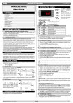
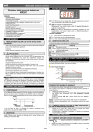
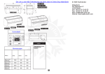
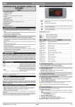
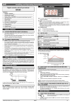
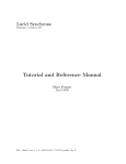
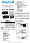
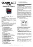
XR01CX - XR02CX - XR03CX - XR04CX - XR06CX
5. GENERAL DESCRIPTION
EN13485 S A 1 - 2
Model XR01CX, in 32x74x50 mm short format, is a single stage temperature thermostat
suitable for applications in the field of refrigeration or heating. It provides a relay output to drive
the compressor. It is also provided with 1 NTC probe input and one digital input. The
instrument is fully configurable through special parameters that can be easily programmed
XR01CX DIGITAL THERMOSTAT
through the keyboard or by the HOTKEY.
XR02CX DIGITAL CONTROLLER WITH “OFF CYCLE” DEFROST
Model XR02CX, in 32x74x50 mm short format, is a digital controller with off cycle defrost
designed for refrigeration applications at normal temperature. It provides a relay output to
XR03CX DIGITAL CONTROLLER WITH AUXILIARY RELAY
drive the compressor. It is also provided with 1 NTC probe input and one the digital input. The
XR04CX DIGITAL CONTROLLER WITH DEFROST RELAY
XR06CX DIGITAL CONTROLLER WITH DEFROST AND FANS MANAGEMENT instrument is fully configurable through special parameters that can be easily programmed
through the keyboard or by the HOTKEY.
The XR03CX, in 32x74x50 mm short format, is microprocessor based controller suitable for
applications on normal temperature refrigerating units. It provides two relay output: one for
SZ02 1599010030 V.1.0 2013.07.17
compressor and the other one for alarm signalling or as auxiliary output. It provides an NTC
probe input and a digital input for alarm signalling, for switching the auxiliary output or for start
OPERATING MANUAL
defrost. The instrument is fully configurable through special parameters that can be easily
programmed through the keyboard or the by HOTKEY.
1. GENERAL WARNINGS
The XR04CX, in 32x74x50 mm short format, is microprocessor based controller suitable for
applications on normal or low temperature refrigerating units. It provides two relay output: one
1.1 PLEASE READ BEFORE USING THIS MANUAL
• This manual is part of the product and should be kept near the instrument for easy and quick for compressor and the other one for defrost. It provides two NTC probe inputs, one for room
temperature and other one to control defrost termination. The instrument is fully configurable
reference.
• The instrument shall not be used for purposes different from those described hereunder. It through special parameters that can be easily programmed through the keyboard or by the
HOTKEY.
cannot be used as a safety device.
The XR06CX, format 32x74x60 mm, is microprocessor based controller, suitable for
• Check the application limits before proceeding
• Dixell Srl reserves the right to change the composition of its products, even without notice, applications on medium or low temperature ventilated refrigerating units. It has three relay
outputs to control compressor, fan, and defrost, which can be either electrical or reverse cycle
ensuring the same and unchanged functionality.
(hot gas). It is also provided with 2 NTC probe inputs, the first one for temperature control, the
1.2 SAFETY PRECAUTIONS
second one, to be located onto the evaporator, to control the defrost termination temperature
• Check the supply voltage is correct before connecting the instrument.
and to managed the fan and it's provided with a configurable digital input. With the HOTKEY
• Do not expose to water or moisture: use the controller only within the operating limits avoiding it's possible to program the instrument in a quick and easy way.
sudden temperature changes with high atmospheric humidity to prevent formation of
condensation.
6. REGULATION
• Warning: disconnect all electrical connections before any kind of maintenance.
6.1 THE REGULATION OUTPUT (Only for XR01CX)
• Fit the probe where it is not accessible by the End User. The instrument must not be opened.
• In case of failure or faulty operation send the instrument back to the distributor or to “Dixell The regulation is performed according to the temperature measured by probe. The instrument
is provided with the CH programmable parameter wich enables the user to set the regulation
S.r.l.” (see address) with a detailed description of the fault.
both for heating or cooling applications:
• Consider the maximum current which can be applied to each relay (see Technical Data).
CH=cL --> cooling applications;
• Ensure that the wires for probes, loads and the power supply are separated and far enough •
•
CH=Ht --> heating applications.
from each other, without crossing or intertwining.
• In case of applications in industrial environments, the use of mains filters (our mod. FT1) in 6.2 COOLING APPLICATIONS
parallel with inductive loads could be useful.
The regulation is performed according to the temperature measured by the thermostat probe
with a positive differential from the set point: if the temperature increases and reaches set
1.3 DISPOSAL OF THE PRODUCT
point plus differential the compressor is started and then turned off when the temperature
The appliance (or the product) must be disposed of separately in accordance with
reaches the set point value again.
the local waste disposal legislation in force.
6.3 HEATING APPLICATIONS (Only XR01CX)
The Hy value is automatically subtracted to the SET POINT. If the temperature decreases and
2. FRONT PANEL
reaches set point minus differential the output is started and then turned off when the
temperature reaches set point value again.
GB
aux
3. DIMENSIONS AND CUT OUT
BRACKET
BRACKET
29
36,9
71
78
,5
9. FRONT PANEL COMMANDS
6
To display target set point, in programming mode it selects a parameter or confirm
an operation
4. CONNECTIONS
To start a manual defrost
In programming mode it browses the parameter codes or increases the displayed
value
XR01CX - XR02CX 8A or 20A COMP.
In programming mode it browses the parameter codes or decreases the displayed
value
aux
*
HOT KEY
*
4
3
6
Dig Input
2
Room
1
KEYS COMBINATION
+ To lock or unlock the keyboard
8(3)A/250Vac
or
20(8)A/250Vac
9
8
7
+
+
Power Line
Supply
Comp
LED
To enter in programming mode
MODE
Flashing
XR03CX 8A or 20A COMP.
*
*
6
3 4
16FLA(96LRA)
20(8)A 250V
XR04CX 8A or 20A COMP.
*
8(3)A/250Vac
or
20(8)A/250Vac 8(3)A/250Vac
HOT KEY
2
3
16FLA(96LRA)
20(8)A 250V
7
9 10 11 12
8
Power Line
Supply
Line n.c.
Def
Comp
Evap
Room
XR06CX 8A COMP.
Dig Input
*
6
4
Evap
Room
1
9 10 11 12
8(3)A/250Vac 8(3)A/250Vac
8(3)A/250Vac
Max
8A
1
2
3
4
7
7
5
n.c.
Line
Fan Comp
Def
8 for 12, 24Vac/dc
8
Power
Supply
HOT KEY
Room
Evap
Dig Input
XR06CX 16A or 20A COMP.
9 10 11 12
5(2)A/250Vac 16(5)A/250Vac
or
20(8)A/250Vac
Max
*
8(3)A/250Vac
20A
1
*
16FLA(96LRA)
20(8)A 250V
Line
2
3
4
5
6 7
8
n.c.
Power Line
Def
Fan Comp Supply
HOT KEY
15. TECHNICAL DATA
Housing: self extinguishingABS.
Case: frontal 32x74 mm; depth 50 or 60mm.
Mounting: panel mounting in a 71x29mm panel cut-out.
Protection: IP20.
Frontal protection: IP65.
Connections: Screw terminal block 2,5 mm2 wiring.
Power supply: according to the model: 12Vac/dc, ±10%; 24Vac/dc, ±10%; 230Vac 10%,
50/60Hz, 110Vac 10%, 50/60Hz.
Power absorption: 3,5VAmax.
Display: 2 digits, red LED, 14,2 mm high.
Inputs: Up to 2 NTC.
Digital input: free voltage contact.
Relay outputs: compressor: SPST 8(3) A, 250Vac; SPST 16(6)A 250Vac or 20(8)A
250Vac;
defrost/aux: SPDT 8(3)A, 250Vac;
fan: SPST 8(3)A, 250Vac or SPST 5(2)A.
Data storing: on the non-volatile memory (EEPROM).
Kind of action: 1B.
Pollution grade: 2.
Software class: A.
Rated impulsive voltage: 2500V.
Overvoltage Category: II.
Operating temperature: 0÷60 °C.
Storage temperature: -30÷85 °C.
Relative humidity: 20÷85% (no condensing).
Measuring and regulation range: NTC -40÷110°C (-40÷230°F).
Resolution: 0,1 °C or 1°C or 1 °F (selectable).
Accuracy (ambient temp. 25°C): ±0,7 °C ±1 digit.
DEFAULT SETTING VALUES
LABEL DESCRIPTION
RANGE
XR01CX
XR02CX
XR03CX
XR04CX
LS - US
0.1÷25°C/
1÷45°F
-55°C÷SET/
-67°F÷SET
5.0
3.0
3.0
-5.0
XR06CX
-5.0
2.0°C/4°F
2.0°C/4°F
2.0°C/4°F
2.0°C/4°F
2.0°C/4°F
-55°C/
-55°F
-55°C/
-55°F
-55°C/
-55°F
-55°C/
-55°F
-55°C/
-55°F
Set
Set Point
Hy
Differential
LS
Minimum Set Point
US
Maximum Set Point
SET÷99°C/
99 °C / 99°F 99 °C / 99°F 99 °C / 99°F 99 °C / 99°F 99 °C / 99°F
SET÷99°F
ot
First probe calibration
-9.9÷9.9°C/
-17÷17°F
0.0
0.0
0.0
0.0
P2
Second probe presence: n= not present; y= present
n-y
–
–
–
y
y
oE
Second probe calibration
-9.9÷9.9°C/
-17÷17°F
–
–
–
0.0
0.0
0.0
od
Outputs activation delay at start up
0 ÷ 99 min
0
0
0
0
0
AC
Anti-short cycle delay
0 ÷ 50 min
1
1
1
1
1
Cy
Comp. ON time faulty probe. Cy= 0 comp. always OFF
0 ÷ 99 min
15
15
15
15
15
Cn
CH
Comp. OFF time faulty probe. Cn= 0 comp. always active
Kind of action
0 ÷ 99 min
cL ÷ Ht
30
cL
30
cL
30
cL
30
–
30
–
CF
Measurement units: °C= Celsius; °F= Fahrenheit
°C / °F
°C / °F
°C / °F
°C / °F
°C / °F
°C / °F
rE
Resolution (only for °C): dE= decimal between -9.9 and 9.9°C; in= integer
dE – in
dE
dE
dE
dE
dE
Ld
Default display: P1= thermostat probe; P2= evaporator probe; SP= Set point
P1-P2-SP
–
–
–
P1
P1
dy
Display delay
Defrost type: EL= electrical heater, compressor OFF; in= hot gas, compressor
ON
0 ÷ 15 min
0
0
0
0
0
EL-in
–
–
–
EL
EL
–
–
–
–
8
8
8.0 °C/
46 °F
6
8.0 °C/
46 °F
6
0 ÷ 99 min
–
20
20
30
30
DESCRIPTION
Compressor enabled
td
Anti short cy cle delay enabled (AC parameter)
-55÷50°C/
-67÷99°F
0 ÷ 99 h
Flashing
Dripping in progress
id
Interval between def. cycles
On
Fans output enabled
Md
Max length for def. When ot= n, not evap. probe: timed def. it sets the def.
duration; when ot= y (def. end based on temp.) it sets the max length for def.
dd
Start defrost delay
0 ÷ 99 min
–
–
–
0
0
dF
Display during def.: rt= real temp.; it= start def. temp; St= SET-POINT; dF= label
Df
rt-in-SP-dF
–
it
it
it
it
On
Line n.c.
Power Line
Supply
AUX
Comp
14.1 ALARM RECOVERY
Probe alarms P1 and P2 start some seconds after the fault in the related probe; they
automatically stop some seconds after the probe restarts normal operation. Check
connections before replacing the probe. Temperature alarms HA and LA automatically stop
as soon as the temperature returns to normal values.
Alarms EA and CA (with iF=bL) recover as soon as the digital input is disabled.
Defrost termination temp.
Flashing
8 9 10 11 12
7
Compressor and fans restarts
dE
Flashing
Dig Input
2
Room
1
12. ELECTRICAL CONNECTIONS
All outputs OFF
Door Open
Defrost in progress
On
HOT KEY
Instruments shall be mounted on vertical panel, in a 29x71 mm hole, and fixed using the
special bracket supplied.
The temperature range allowed for correct operation is 0÷60°C. Avoid places subject to strong
vibrations, corrosive gases, excessive dirt or humidity. The same recommendations apply to
probes. Let air circulate by the cooling holes.
Serious external alarm
“dA”
On
Flashing
8(3)A/250Vac
or
20(8)A/250Vac 8(3)A/250Vac
11. INSTALLATION AND MOUNTING
“CA”
To return to room temperature display
On
16FLA(96LRA)
20(8)A 250V
10.3 SERIOUS ALARM (iF=bA)
When the digital input is activated, the unit will wait for di delay before signalling the CA alarm
message. The relay outputs are switched OFF. The alarm will stop as soon as the digital input is
de-activated.
10.4 SWITCHING SECOND RELAY ON (iF=Au) (Only XR03CX)
When o1=Au it switches on and off the second relay.
10.5 START DEFROST (iF=dF)
It starts a defrost if there are the right conditions. After the defrost is finished, the normal
regulation will restart only if the digital input is disabled otherwise the instrument will wait until
the dd safety time is expired.
10.6 INVERSION OF THE KIND OF ACTION: HEATING - COOLING (iF=Hc)
This function allows to invert the regulation of the controller: from cooling to heating and
viceversa.
The instruments are provided with screw terminal block to connect cables with a cross section
up to 2,5 mm2. Before connecting cables make sure the power supply complies with the
instrument's requirements. Separate the probe cables from the power supply cables, from the
outputs and the power connections. Do not exceed the maximum current allowed on each
relay, in case of heavier loads use a suitable external relay.
12.1 PROBES
7. DEFROST
The probes shall be mounted with the bulb upwards to prevent damages due to casual liquid
XR02CX - XR03CX: Defrost is performed through a simple stop of the compressor. Parameter infiltration. It is recommended to place the thermostat probe away from air streams to correctly
id controls the interval between defrost cycles, while its length is controlled by parameter Md. measure the average room temperature. Place the defrost termination probe among the
evaporator fins in the coldest place, where most ice is formed, far from heaters or from the
XR04CX - XR06CX: Two defrost modes are available through the td parameter:
warmest place during defrost, to prevent premature defrost termination.
•
td=EL defrost through electrical heater (compressor OFF);
•
td=in hot gas defrost (compressor ON).
13. HOW TO USE THE HOT KEY
Other parameters are used to control the interval between defrost cycles (id), its maximum
length (Md) and two defrost modes: timed or controlled by the evaporator's probe. At the end 13.1 HOW TO PROGRAM THE HOT KEY FROM THE INSTRUMENT (UPLOAD)
of defrost dripping time is started, its length is set in the dt parameter. With dt=0 the dripping 1. Program one controller with the front keypad;
time is disabled.
2. When the controller is ON, insert the Hot key and pusho key; the uP message appears
followed a by flashing Ed;
8. FANS (Only XR06CX)
3. Push SET key and the Ed will stop flashing;
4. Turn OFF the instrument remove the Hot Key, then turn it ON again.
With FC parameter it can be selected the fans functioning:
NOTE: the Er message is displayed for failed programming. In this case push again o key if
• FC=cn will switch ON and OFF with the compressor and not run during defrost
you want to restart the upload again or remove the Hot key to abort the operation.
• FC=on fans will run even if the compressor is off, and not run during defrost
After defrost, there is a timed fan delay allowing for drip time, set by means of the Fd
parameter.
• FC=cy fans will switch ON and OFF with the compressor and run during defrost
• FC=oY fans will run continuously also during defrost.
An additional parameter FS provides the setting of temperature, detected by the evaporator
probe, above which the fans are always OFF. This is used to make sure circulation of air only if
his temperature is lower than set in FS.
8.1 FANS AND DIGITAL INPUT
When the digital input is configured as door switch iF=do, fans and compressor status
depends on the dC parameter value:
dC=no normal regulation;
dC=Fn fans OFF;
dC=cP compressor OFF;
dC=Fc compressor and fans OFF.
When rd=y, the regulation restart with door open alarm.
PANEL
13.2 HOW TO PROGRAM AN INSTRUMENT USING HOT KEY (DOWNLOAD)
9.7 TO UNLOCK THE KEYBOARD
Keep pressed together for more than 3s the o andn keys till the On message will be 1. Turn OFF the instrument;
2. Insert a programmed Hot Key into the 5 PIN receptacle and then turn the Controller ON;
displayed.
3. Automatically the parameter list of the Hot Key is downloaded into the Controller memory,
10. DIGITAL INPUTS
the do message is blinking followed a by flashing Ed;
The free voltage digital input is programmable in different configurations by the iF parameter. 4.After 10 seconds the instrument will restart working with the new parameters;
5. Remove the Hot Key.
10.1 DOOR SWITCH (iF=do)
NOTE: the Er message is displayed for failed programming. In this case push again o key if
It signals the door status and the corresponding relay output status through the dC parameter: you want to restart the upload again or remove the Hot key to abort the operation.
no = normal (any change); Fn = Fan OFF; CP = Compressor OFF; FC = Compressor and fan
OFF.
14. ALARM SIGNALLING
Since the door is opened, after the delay time set through parameter di, the door alarm is
enabled, the display shows the message dA and the regulation restarts if rd = y. The alarm MESS.
CAUSE
OUTPUTS
stops as soon as the external digital input is disabled again. With the door open, the high and
"P1" Room probe failure
Compressor output according to “Cy” and “Cn”
low temperature alarms are disabled.
"P2" Evaporator probe failure
Defrost end is timed
10.2 EXTERNALALARM (iF=EA)
As soon as the digital input is activated the unit will wait for di time delay before signalling the "HA" Maximum temperature alarm Outputs unchanged
EA alarm message. The outputs status don't change. The alarm stops just after the digital input "LA" Minimum temperature alarm Outputs unchanged
is de-activated.
“EA” External alarm
Outputs unchanged
Fans delay after defrost
Measurement unit
Programming mode
Measurement unit
Programming mode
9.1 HOW TO SEE THE SET POINT
1. Push and immediately release the SET key, the set point will be showed;
2. Push and immediately release the SET key or wait about 5s to return to normal visualisation.
9.2 HOW TO CHANGE THE SETPOINT
1. Push the SET key for more than 3 seconds to change the Set point value;
2. The value of the set point will be displayed and the °C or °F LED starts blinking;
3. To change the SET value push theo or n arrows within 10s;
4. To memorise the new set point value push the SET key again or wait 10s.
9.3 HOW TO START A MANUAL DEFROST
Push the DEF
key for more than 2 seconds and a manual defrost will start.
9.4 HOW TO CHANGE A PARAMETER VALUE
To change the parameter's value operate as follows:
1. Enter the Programming mode by pressing the SET+ n keys for 3s (°C or °F LED starts
blinking);
2. Select the required parameter. Press the SET key to display its value;
3. Use o or n to change its value;
4. Press SET to store the new value and move to the following parameter.
To exit: Press SET+ o or wait 15s without pressing a key.
NOTE: the set value is stored even when the procedure is exited by waiting the time-out to
expire.
dt
Drip time
0 ÷ 99 min
–
–
–
0
0
dP
Defrost at power-on: y= at power on defrost starts; n= defrost doesn’t start at
power-on
y-n
–
–
–
n
n
FC
Fans operating mode: cn= in runs with the comp., OFF during def.;
on= continuous mode, OFF during def.; cY= runs with the comp, ON during def.;
oY= continuous mode, ON during def.
cn–on
–cY–oY
–
–
–
–
o-n
Fd
Fans delay after defrost
FS
Fans stop temperature
AU
Max temperature alarm
9.6 TO LOCK THE KEYBOARD
Keep pressed for more than 3s the o andnkeys.
The OF message will be displayed and the keyboard will be locked. If a key is pressed more
than 3s the OF message will be displayed.
–
–
–
–
–
–
–
–
99 °C/
99 °F
-55 °C/
-55 °F
99 °C/
99 °F
-55 °C/
-55 °F
99 °C/
99 °F
-55 °C/
-55 °F
99 °C/
99 °F
-55 °C/
-55 °F
10
2.0 °C/
36 °F
99 °C/
99 °F
-55 °C/
-55 °F
AL
Min temperature alarm
Ad
Temperature alarm delay
0 ÷ 99 min
15
15
15
15
15
dA
Exclusion of temp. alarm at startup
0 ÷ 99 min
60
90
90
90
90
tb
Silencing buzzer: n= silencing disabled, alarm relay stays on till alarm conditions
lasts; y= silencing enabled: alarm relay is switched OFF by pressing a key
during an alarm
y–n
–
–
y
–
–
o1
Auxiliary relay configuration: dF= defrost; Fn= Fans; AL= Alarm; AU= auxiliary; dF / Fn / AL /
db= neutral zone
Au / db
–
–
AU
–
–
Ap
Alarm relay polarity: cL= when active is closed; OP= when active is opened
cL – OP
–
–
cL
–
–
iP
Digital input polarity: oP= activated by closing the contact; cL= activated by
opening the contact
cL – oP
cL
cL
cL
–
cL
iF
Digital input configuration: EA= external alarm: “EA” message is displayed; EA / bA / do /
bA= serious alarm “CA” message is displayed; do= door switch function; dF / Au / db /
dF= def. activation; Au= not used; Hc= inversion of the kind of action
Hc
EA
EA
do
–
do
di
Digital input delay. With iF= EL or bA delay between the detection of the
external alarm condition and its signalling. With iF= do it represents the delay to
activate the door open alarm
5
5
15
–
15
dC
Comp. and fan status when open door: no= normal; Fn= Fans OFF; no / Fn / cP /
cP= Comp. OFF; Fc= Comp. and fans OFF
Fc
no
no
no
–
FC
rd
Regulation with door open: n= no regulation if door is opened; Y= when di is
elapsed regulation restarts even if door open alarm is present
n-Y
y
y
y
–
y
d1
Thermostat probe display
Read only
–
–
–
–
–
d2
Evaporator probe display
Read only
–
–
–
–
–
Pt
rL
Parameter code table
Firmware release
Read only
Read only
–
–
–
–
–
–
–
–
–
–
9.5 HIDDEN MENU
The hidden menu includes all the parameters of the instrument.
HOW TO ENTER THE HIDDEN MENU
1. Enter the Programming mode by pressing the SET+ n keys for 3s (°C or °F LED starts
blinking);
2. Released the keys, then push again the SET+ n keys for more than 7s. The L2 label will be
displayed immediately followed from the Hy parameter.
NOW YOU ARE IN THE HIDDEN MENU.
3. Select the required parameter;
4. Press the SET key to display its value;
5. Use o or n to change its value;
6. Press SET to store the new value and move to the following parameter.
To exit: Press SET+o or wait 15s without pressing a key.
NOTE1: if none parameter is present in L1, after 3s the nP message is displayed. Keep the
keys pushed till the L2 message is displayed.
NOTE2: the set value is stored even when the procedure is exited by waiting the time-out to
expire.
HOW TO MOVE A PARAMETER FROM THE HIDDEN MENU TO THE FIRST LEVEL AND
VICEVERSA.
Each parameter present in the HIDDEN MENU can be removed or put into “THE FIRST
LEVEL” (user level) by pressing SET+n . In HIDDEN MENU when a parameter is present in
First Level the decimal point is on.
0 ÷ 99 min
-55÷50°C/
-67÷99°F
ALL÷99°C/
ALL÷99°F
-55°C÷ALU/
-67°F÷ALU
0 ÷ 99 min