1
MELSEC-Q/L AnyWire DB A20 Master Module
User's Manual
-QJ51AW12D2
-LJ51AW12D2
COPYRIGHT
This document is protected by the law of copyright, whereby all rights established therein remain with the company
Mitsubishi Electric Corporation. Reproduction of this document or parts of this document is only permissible within the
limits of the legal determination of Copyright Law. Alteration or abridgement of the document is not permitted without
the explicit written approval of the company Mitsubishi Electric Corporation.
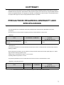
PRECAUTIONS REGARDING WARRANTY AND
SPECIFICATIONS
The QJ51AW12D2 and LJ51AW12D2 were jointly developed and manufactured by Mitsubishi and Anywire
Corporation.
Note that there are some precautions regarding warranty and specifications of this product.
<Warranty>
Other programmable controller
Item
QJ51AW12D2, LJ51AW12D2
products
(e.g. MELSEC-Q series)
Repair term after discontinuation of
production
1 years
7 years
<Specifications>
The general specifications of the QJ51AW12D2 are the same as those of other MELSEC-Q series except under the
following condition.
When setting the transmission clock at 125kHz by using the module whose serial number (sixth digit) is 5 or earlier,
apply within the following specified range:
Voltage range of external power supply: 21.6 to 25.2VDC
Operating ambient temperature: 0 to 50
The general specifications of the LJ51AW12D2 are the same as those of other MELSEC-L series.
<Application of the EMC Directive>
Other programmable controller
Item
QJ51AW12D2
LJ51AW12D2
products
(e.g. MELSEC-Q series)
Applicable EMC standard
*1
EN61131-2*1
EN61131-2
EN61131-2
The module with a serial number where the sixth digit is "3" or later complies with this standard.
1
<Application of the UL/cUL standards>
Other programmable controller
Item
QJ51AW12D2
products
LJ51AW12D2
(e.g. MELSEC-Q series)
Applicable UL standard/cUL standard
*2
*3
2
UL508*2
CSA22.2
UL508*3
*2
UL508
*3
CSA22.2
CSA22.2
The module with a serial number where the sixth digit is "4" or later complies with this standard.
The module with a serial number where the sixth digit is "2" or later complies with this standard.
SAFETY PRECAUTIONS
(Read these precautions before using this product.)
Before using this product, please read this manual and the relevant manuals carefully and pay full attention
to safety to handle the product correctly.
The precautions given in this manual are concerned with this product only. For the safety precautions of the
programmable controller system, refer to the user's manual for the CPU module used.
In this manual, the safety precautions are classified into two levels: "
WARNING" and "
CAUTION".
WARNING
Indicates that incorrect handling may cause hazardous conditions,
resulting in death or severe injury.
CAUTION
Indicates that incorrect handling may cause hazardous conditions,
resulting in minor or moderate injury or property damage.
Under some circumstances, failure to observe the precautions given under "
CAUTION" may lead to
serious consequences.
Observe the precautions of both levels because they are important for personal and system safety.
Make sure that the end users read this manual and then keep the manual in a safe place for future
reference.
3
When the QJ51AW12D2 is used
[Design Precautions]
WARNING
● An AnyWire DB A20 system has no control function for ensuring safety.
● When connecting a peripheral with the programmable controller CPU or a personal computer with an
intelligent function module to modify data of a running programmable controller, configure an interlock
circuit in the sequence program to ensure that the entire system will always operate safely. For other
forms of control (such as program modification or operating status change) of a running
programmable controller, read the relevant manuals carefully and ensure that the operation is safe
before proceeding. Especially, when a remote programmable controller is controlled by an external
device, immediate action cannot be taken if a problem occurs in the programmable controller due to a
communication failure. To prevent this, configure an interlock circuit in the sequence program, and
determine corrective actions to be taken between the external device and CPU module in case of a
communication failure.
● Do not write any data to the "system area" of the buffer memory in the intelligent function module.
Also, do not use any "use prohibited" signals as an output signal from the programmable controller
CPU to the intelligent function module. Doing so may cause malfunction of the programmable
controller system.
[Design Precautions]
CAUTION
● Although an AnyWire DB A20 system features high noise immunity, keep a distance of 100mm or
more between the transmission cables or I/O cables and the high-voltage cables or power cables.
Failure to do so may cause malfunction.
● Configure safety circuits, such as an emergency stop circuit and interlock circuit, external to the
AnyWire DB A20 system.
4
[Installation Precautions]
WARNING
● Use the programmable controller in an environment that meets the general specifications in the user's
manual for the CPU module used.
Failure to do so may result in electric shock, fire, malfunction, or damage to or deterioration of the
product.
● To mount the module, while pressing the module mounting lever located in the lower part of the
module, fully insert the module fixing projection(s) into the hole(s) in the base unit and press the
module until it snaps into place.
Incorrect interconnection may cause malfunction, failure, or drop of the module.
When using the programmable controller in an environment of frequent vibrations, fix the module with
a screw.
Tighten the screw within the specified torque range.
Undertightening can cause drop of the screw, short circuit, or malfunction.
Overtightening can damage the screw and/or module, resulting in drop, short circuit, or malfunction.
● Shut off the external power supply (all phases) used in the system before mounting or removing a
module.
Failure to do so may result in damage to the product.
● Do not directly touch any conductive parts and electronic components of the module.
Doing so can cause malfunction or failure of the module.
5
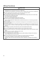
[Wiring Precautions]
CAUTION
● Tighten the terminal screw within the specified torque range.
Undertightening can cause short circuit, fire or malfunction.
Overtightening can damage the screw and/or module, resulting in drop, short circuit, or malfunction.
● Prevent foreign matter such as dust or wire chips from entering the module.
Such foreign matter can cause a fire, failure, or malfunction.
● A protective film is attached to the top of the module to prevent foreign matter, such as wire chips,
from entering the module during wiring.
Do not remove the film during wiring.
Remove it for heat dissipation before system operation.
● Incorrect wiring may damage modules and external devices.
Adjust a cable length and a module position to prevent disconnection of a connector type terminal
block or a cable.
● Do not solder stranded wires of a cable when connecting them to the terminal block. Doing so may
cause poor contact.
● The power supply voltage of remote slave modules may be insufficient due to a voltage drop in the
power supply line. Connect an external power supply so that the voltage of remote slave modules is
ensured.
● Do not apply the 24VDC power before wiring the entire AnyWire DB A20 system.
● Use 24VDC stabilized power supplies for devices in the AnyWire DB A20 system.
● Do not install the control lines or communication cables together with the main circuit lines or power
cables.
Failure to do so may result in malfunction due to noise.
● Place the cables in a duct or clamp them.
If not, dangling cable may swing or inadvertently be pulled, resulting in damage to the module or
cables or malfunction due to poor contact.
● When disconnecting the cable from the module, do not pull the cable by the cable part.
For the cable connected to the terminal block, loosen the terminal screw.
Pulling the cable connected to the module may result in malfunction or damage to the module or
cable.
6
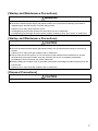
[Startup and Maintenance Precautions]
WARNING
● Do not touch any terminal while power is on. Doing so will cause electric shock or malfunction.
● Shut off the external power supply (all phases) used in the system before cleaning the module or
retightening the terminal screws or module fixing screws.
Failure to do so may result in electric shock.
Undertightening the terminal screws can cause short circuit or malfunction.
Overtightening can damage the screw and/or module, resulting in drop, short circuit, or malfunction.
[Startup and Maintenance Precautions]
CAUTION
● Do not disassemble or modify the modules. Doing so may cause failure, malfunction, injury, or a fire.
● Shut off the external power supply (all phases) used in the system before mounting or removing a
module.
Failure to do so may cause the module to fail or malfunction.
● After the first use of the product, do not mount/remove the module to/from the base unit, and the
terminal block to/from the module more than 50 times (IEC 61131-2 compliant) respectively.
Exceeding the limit of 50 times may cause malfunction.
● Before handling the module, touch a grounded metal object to discharge the static electricity from the
human body.
Failure to do so may cause the module to fail or malfunction.
[Disposal Precautions]
CAUTION
● When disposing of this product, treat it as industrial waste.
7
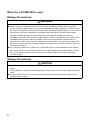
When the LJ51AW12D2 is used
[Design Precautions]
WARNING
● An AnyWire DB A20 system has no control function for ensuring safety.
● When connecting a peripheral with the CPU module or a personal computer with an intelligent
function module to modify data of a running programmable controller, configure an interlock circuit in
the sequence program to ensure that the entire system will always operate safely. For other forms of
control (such as program modification or operating status change) of a running programmable
controller, read the relevant manuals carefully and ensure that the operation is safe before
proceeding. Especially, when a remote programmable controller is controlled by an external device,
immediate action cannot be taken if a problem occurs in the programmable controller due to a
communication failure. To prevent this, configure an interlock circuit in the sequence program, and
determine corrective actions to be taken between the external device and CPU module in case of a
communication failure.
● Do not write any data to the "system area" of the buffer memory in the intelligent function module.
Also, do not use any "use prohibited" signals as an output signal from the programmable controller
CPU to the intelligent function module. Doing so may cause malfunction of the programmable
controller system.
[Design Precautions]
CAUTION
● Do not install the control lines or communication cables together with the main circuit lines or power
cables.
Keep a distance of 100mm or more between them. Failure to do so may result in malfunction due to
noise.
● Configure safety circuits, such as an emergency stop circuit and interlock circuit, external to the
AnyWire DB A20 system.
8
[Installation Precautions]
WARNING
● Shut off the external power supply (all phases) used in the system before mounting or removing the
module.
Failure to do so may result in electric shock or cause the module to fail or malfunction.
[Installation Precautions]
CAUTION
● Use the programmable controller in an environment that meets the general specifications in the Safety
Guidelines provided with the CPU module or head module. Failure to do so may result in electric
shock, fire, malfunction, or damage to or deterioration of the product.
● To interconnect modules, engage the respective connectors and securely lock the module joint levers.
Incorrect interconnection may cause malfunction, failure, or drop of the module.
● Tighten the screws within the specified torque range. Undertightening can cause drop of the screw,
short circuit, or malfunction. Overtightening can damage the screw and/or module, resulting in drop,
short circuit, or malfunction.
● Do not directly touch any conductive parts and electronic components of the module.
Doing so can cause malfunction or failure of the module.
9
[Wiring Precautions]
CAUTION
● Tighten the terminal screw within the specified torque range.
Undertightening can cause short circuit, fire or malfunction.
Overtightening can damage the screw and/or module, resulting in drop, short circuit, or malfunction.
● Prevent foreign matter such as dust or wire chips from entering the module.
Such foreign matter can cause a fire, failure, or malfunction.
● A protective film is attached to the top of the module to prevent foreign matter, such as wire chips,
from entering the module during wiring.
Do not remove the film during wiring.
Remove it for heat dissipation before system operation.
● Incorrect wiring may damage modules and external devices.
Adjust a cable length and a module position to prevent disconnection of a connector type terminal
block or a cable.
● Do not solder stranded wires of a cable when connecting them to the terminal block. Doing so may
cause poor contact.
● The power supply voltage of remote slave modules may be insufficient due to a voltage drop in the
power supply line. Connect an external power supply so that the voltage of remote slave modules is
ensured.
● Do not apply the 24VDC power before wiring the entire AnyWire DB A20 system.
● Use 24VDC stabilized power supplies for devices in the AnyWire DB A20 system.
● Do not install the control lines or communication cables together with the main circuit lines or power
cables.
Failure to do so may result in malfunction due to noise.
● Place the cables in a duct or clamp them.
If not, dangling cable may swing or inadvertently be pulled, resulting in damage to the module or
cables or malfunction due to poor contact.
● When disconnecting the cable from the module, do not pull the cable by the cable part.
For the cable connected to the terminal block, loosen the terminal screw.
Pulling the cable connected to the module may result in malfunction or damage to the module or
cable.
10
[Startup and Maintenance Precautions]
WARNING
● Do not touch any terminal while power is on. Doing so will cause electric shock or malfunction.
● Shut off the external power supply (all phases) used in the system before cleaning the module or
retightening the terminal block screws. Failure to do so may result in electric shock.
[Startup and Maintenance Precautions]
CAUTION
● Do not disassemble or modify the module.
Doing so may cause failure, malfunction, injury, or a fire.
● Shut off the external power supply (all phases) used in the system before mounting or removing a
module.
Failure to do so may cause the module to fail or malfunction.
● Tighten the terminal block screws within the specified torque range. Undertightening can cause drop
of the component or wire, short circuit, or malfunction. Overtightening can damage the screw and/or
module, resulting in drop, short circuit, or malfunction.
● After the first use of the product (module, display unit, and terminal block), the number of
connections/disconnections is limited to 50 times (in accordance with IEC 61131-2).
Exceeding the limit may cause malfunction.
● Before handling the module, touch a conducting object such as a grounded metal to discharge the
static electricity from the human body.
Failure to do so may cause the module to fail or malfunction.
[Disposal Precautions]
CAUTION
● When disposing of this product, treat it as industrial waste.
11
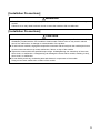
CONDITIONS OF USE FOR THE PRODUCT
(1) Mitsubishi programmable controller ("the PRODUCT") shall be used in conditions;
i) where any problem, fault or failure occurring in the PRODUCT, if any, shall not lead to any major or serious accident;
and
ii) where the backup and fail-safe function are systematically or automatically provided outside of the PRODUCT for the
case of any problem, fault or failure occurring in the PRODUCT.
(2) The PRODUCT has been designed and manufactured for the purpose of being used in general industries.
MITSUBISHI SHALL HAVE NO RESPONSIBILITY OR LIABILITY (INCLUDING, BUT NOT LIMITED TO ANY AND ALL
RESPONSIBILITY OR LIABILITY BASED ON CONTRACT, WARRANTY, TORT, PRODUCT LIABILITY) FOR ANY
INJURY OR DEATH TO PERSONS OR LOSS OR DAMAGE TO PROPERTY CAUSED BY the PRODUCT THAT ARE
OPERATED OR USED IN APPLICATION NOT INTENDED OR EXCLUDED BY INSTRUCTIONS, PRECAUTIONS, OR
WARNING CONTAINED IN MITSUBISHI'S USER, INSTRUCTION AND/OR SAFETY MANUALS, TECHNICAL
BULLETINS AND GUIDELINES FOR the PRODUCT.
("Prohibited Application")
Prohibited Applications include, but not limited to, the use of the PRODUCT in;
• Nuclear Power Plants and any other power plants operated by Power companies, and/or any other cases in which the
public could be affected if any problem or fault occurs in the PRODUCT.
• Railway companies or Public service purposes, and/or any other cases in which establishment of a special quality
assurance system is required by the Purchaser or End User.
• Aircraft or Aerospace, Medical applications, Train equipment, transport equipment such as Elevator and Escalator,
Incineration and Fuel devices, Vehicles, Manned transportation, Equipment for Recreation and Amusement, and
Safety devices, handling of Nuclear or Hazardous Materials or Chemicals, Mining and Drilling, and/or other
applications where there is a significant risk of injury to the public or property.
Notwithstanding the above, restrictions Mitsubishi may in its sole discretion, authorize use of the PRODUCT in one or
more of the Prohibited Applications, provided that the usage of the PRODUCT is limited only for the specific
applications agreed to by Mitsubishi and provided further that no special quality assurance or fail-safe, redundant or
other safety features which exceed the general specifications of the PRODUCTs are required. For details, please
contact the Mitsubishi representative in your region.
12
COMPLIANCE WITH EMC AND LOW VOLTAGE
DIRECTIVES
(1) Method of ensuring compliance
To ensure that Mitsubishi programmable controllers maintain EMC and Low Voltage Directives when incorporated
into other machinery or equipment, certain measures may be necessary. Please refer to one of the following
manuals.
• User's manual for the CPU module or head module used
• Safety Guidelines (This manual is included with the CPU module or base unit.)
The CE mark on the side of the programmable controller indicates compliance with EMC and Low Voltage
Directives.
(2) Additional measures
To ensure that this product maintains EMC and Low Voltage Directives, please refer to Page 73, Appendix 1.
13
CONTENTS
CONTENTS
COPYRIGHT . . . . . . . . . . . . . . . . . . . . . . . . . . . . . . . . . . . . . . . . . . . . . . . . . . . . . . . . . . . . . . . . . . . . . . . 1
PRECAUTIONS REGARDING WARRANTY AND SPECIFICATIONS . . . . . . . . . . . . . . . . . . . . . . . . . . . 1
SAFETY PRECAUTIONS . . . . . . . . . . . . . . . . . . . . . . . . . . . . . . . . . . . . . . . . . . . . . . . . . . . . . . . . . . . . . 3
CONDITIONS OF USE FOR THE PRODUCT . . . . . . . . . . . . . . . . . . . . . . . . . . . . . . . . . . . . . . . . . . . . 12
COMPLIANCE WITH EMC AND LOW VOLTAGE DIRECTIVES . . . . . . . . . . . . . . . . . . . . . . . . . . . . . . 13
TERMS . . . . . . . . . . . . . . . . . . . . . . . . . . . . . . . . . . . . . . . . . . . . . . . . . . . . . . . . . . . . . . . . . . . . . . . . . . 16
CHAPTER 1 OVERVIEW
17
CHAPTER 2 SPECIFICATIONS
19
2.1
2.2
2.3
General Specifications . . . . . . . . . . . . . . . . . . . . . . . . . . . . . . . . . . . . . . . . . . . . . . . . . . . . . . . 19
Performance Specifications . . . . . . . . . . . . . . . . . . . . . . . . . . . . . . . . . . . . . . . . . . . . . . . . . . . 20
2.2.1
Performance specifications . . . . . . . . . . . . . . . . . . . . . . . . . . . . . . . . . . . . . . . . . . . . . . . . . . .20
2.2.2
Power supply sequence and handling of I/O data . . . . . . . . . . . . . . . . . . . . . . . . . . . . . . . . . .21
Applicable System . . . . . . . . . . . . . . . . . . . . . . . . . . . . . . . . . . . . . . . . . . . . . . . . . . . . . . . . . . 22
2.3.1
QJ51AW12D2 . . . . . . . . . . . . . . . . . . . . . . . . . . . . . . . . . . . . . . . . . . . . . . . . . . . . . . . . . . . . .22
2.3.2
LJ51AW12D2 . . . . . . . . . . . . . . . . . . . . . . . . . . . . . . . . . . . . . . . . . . . . . . . . . . . . . . . . . . . . . .23
2.4
External Dimensions. . . . . . . . . . . . . . . . . . . . . . . . . . . . . . . . . . . . . . . . . . . . . . . . . . . . . . . . . 24
2.5
Part Names. . . . . . . . . . . . . . . . . . . . . . . . . . . . . . . . . . . . . . . . . . . . . . . . . . . . . . . . . . . . . . . . 26
2.6
Module Mounting . . . . . . . . . . . . . . . . . . . . . . . . . . . . . . . . . . . . . . . . . . . . . . . . . . . . . . . . . . . 27
2.7
Checking Function Version and Serial Number . . . . . . . . . . . . . . . . . . . . . . . . . . . . . . . . . . . . 28
CHAPTER 3 OPERATION MODE
3.1
3.2
QJ51AW12D2 . . . . . . . . . . . . . . . . . . . . . . . . . . . . . . . . . . . . . . . . . . . . . . . . . . . . . . . . . . . . . . 29
3.1.1
Transmission speed setting . . . . . . . . . . . . . . . . . . . . . . . . . . . . . . . . . . . . . . . . . . . . . . . . . . .29
3.1.2
Setting of the number of transmission points, double check mode, and waveform output method31
LJ51AW12D2 . . . . . . . . . . . . . . . . . . . . . . . . . . . . . . . . . . . . . . . . . . . . . . . . . . . . . . . . . . . . . . 37
3.2.1
Setting of the number of transmission points . . . . . . . . . . . . . . . . . . . . . . . . . . . . . . . . . . . . . .39
3.2.2
Transmission speed setting . . . . . . . . . . . . . . . . . . . . . . . . . . . . . . . . . . . . . . . . . . . . . . . . . . .40
3.2.3
Double check mode setting . . . . . . . . . . . . . . . . . . . . . . . . . . . . . . . . . . . . . . . . . . . . . . . . . . .41
3.2.4
Waveform output method setting . . . . . . . . . . . . . . . . . . . . . . . . . . . . . . . . . . . . . . . . . . . . . . .43
CHAPTER 4 PROGRAMMING
4.1
4.2
14
44
I/O Signals with CPU Module . . . . . . . . . . . . . . . . . . . . . . . . . . . . . . . . . . . . . . . . . . . . . . . . . . 44
4.1.1
I/O signal list. . . . . . . . . . . . . . . . . . . . . . . . . . . . . . . . . . . . . . . . . . . . . . . . . . . . . . . . . . . . . . .44
4.1.2
Details of the input signal . . . . . . . . . . . . . . . . . . . . . . . . . . . . . . . . . . . . . . . . . . . . . . . . . . . . .45
4.1.3
Details of the output signal. . . . . . . . . . . . . . . . . . . . . . . . . . . . . . . . . . . . . . . . . . . . . . . . . . . .45
Buffer Memory Area . . . . . . . . . . . . . . . . . . . . . . . . . . . . . . . . . . . . . . . . . . . . . . . . . . . . . . . . . 46
4.2.1
4.3
29
I/O area . . . . . . . . . . . . . . . . . . . . . . . . . . . . . . . . . . . . . . . . . . . . . . . . . . . . . . . . . . . . . . . . . .47
4.2.2
Number of error addresses . . . . . . . . . . . . . . . . . . . . . . . . . . . . . . . . . . . . . . . . . . . . . . . . . . .48
4.2.3
Value of error addresses . . . . . . . . . . . . . . . . . . . . . . . . . . . . . . . . . . . . . . . . . . . . . . . . . . . . .48
4.2.4
Number of connection addresses . . . . . . . . . . . . . . . . . . . . . . . . . . . . . . . . . . . . . . . . . . . . . .49
4.2.5
Value of connection addresses . . . . . . . . . . . . . . . . . . . . . . . . . . . . . . . . . . . . . . . . . . . . . . . .49
4.2.6
Latest error code storage area, latest error ID storage area . . . . . . . . . . . . . . . . . . . . . . . . . .49
Program Example . . . . . . . . . . . . . . . . . . . . . . . . . . . . . . . . . . . . . . . . . . . . . . . . . . . . . . . . . . . 50
CHAPTER 5 MONITORING FUNCTION
5.1
Automatic Address Detection . . . . . . . . . . . . . . . . . . . . . . . . . . . . . . . . . . . . . . . . . . . . . . . . . . 53
5.1.1
5.2
52
Automatic address detection operation . . . . . . . . . . . . . . . . . . . . . . . . . . . . . . . . . . . . . . . . . .53
Monitoring Operation . . . . . . . . . . . . . . . . . . . . . . . . . . . . . . . . . . . . . . . . . . . . . . . . . . . . . . . . 54
CHAPTER 6 LED DISPLAY
55
6.1
QJ51AW12D2 . . . . . . . . . . . . . . . . . . . . . . . . . . . . . . . . . . . . . . . . . . . . . . . . . . . . . . . . . . . . . . 55
6.2
LJ51AW12D2 . . . . . . . . . . . . . . . . . . . . . . . . . . . . . . . . . . . . . . . . . . . . . . . . . . . . . . . . . . . . . . 56
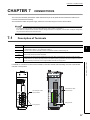
CHAPTER 7 CONNECTIONS
57
7.1
Description of Terminals . . . . . . . . . . . . . . . . . . . . . . . . . . . . . . . . . . . . . . . . . . . . . . . . . . . . . . 57
7.2
Transmission Cable Terminal Block . . . . . . . . . . . . . . . . . . . . . . . . . . . . . . . . . . . . . . . . . . . . . 58
7.3
Cable Processing . . . . . . . . . . . . . . . . . . . . . . . . . . . . . . . . . . . . . . . . . . . . . . . . . . . . . . . . . . . 59
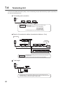
7.4
Terminating Unit . . . . . . . . . . . . . . . . . . . . . . . . . . . . . . . . . . . . . . . . . . . . . . . . . . . . . . . . . . . . 60
CHAPTER 8 TRANSMISSION TIME
8.1
8.2
61
Transmission Cycle Time . . . . . . . . . . . . . . . . . . . . . . . . . . . . . . . . . . . . . . . . . . . . . . . . . . . . . 61
8.1.1
Transmission cycle time of the master module . . . . . . . . . . . . . . . . . . . . . . . . . . . . . . . . . . . .61
8.1.2
Effects of the double check system . . . . . . . . . . . . . . . . . . . . . . . . . . . . . . . . . . . . . . . . . . . . .62
Transmission Delay Time . . . . . . . . . . . . . . . . . . . . . . . . . . . . . . . . . . . . . . . . . . . . . . . . . . . . . 63
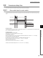
8.2.1
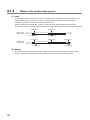
Slave module (input) to master module . . . . . . . . . . . . . . . . . . . . . . . . . . . . . . . . . . . . . . . . . .63
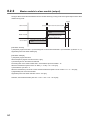
8.2.2
Master module to slave module (output) . . . . . . . . . . . . . . . . . . . . . . . . . . . . . . . . . . . . . . . . .64
CHAPTER 9 TROUBLESHOOTING
65
9.1
Visual Inspection. . . . . . . . . . . . . . . . . . . . . . . . . . . . . . . . . . . . . . . . . . . . . . . . . . . . . . . . . . . . 65
9.2
Check with Input Signals . . . . . . . . . . . . . . . . . . . . . . . . . . . . . . . . . . . . . . . . . . . . . . . . . . . . . 67
9.3
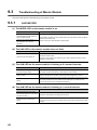
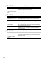
Troubleshooting of Master Module . . . . . . . . . . . . . . . . . . . . . . . . . . . . . . . . . . . . . . . . . . . . . . 68
9.3.1
QJ51AW12D2 . . . . . . . . . . . . . . . . . . . . . . . . . . . . . . . . . . . . . . . . . . . . . . . . . . . . . . . . . . . . .68
9.3.2
LJ51AW12D2 . . . . . . . . . . . . . . . . . . . . . . . . . . . . . . . . . . . . . . . . . . . . . . . . . . . . . . . . . . . . . .69
9.4
Troubleshooting of Slave Module . . . . . . . . . . . . . . . . . . . . . . . . . . . . . . . . . . . . . . . . . . . . . . . 71
9.5
List of Error Codes . . . . . . . . . . . . . . . . . . . . . . . . . . . . . . . . . . . . . . . . . . . . . . . . . . . . . . . . . . 72
APPENDICES
73
Appendix 1 EMC and Low Voltage Directives . . . . . . . . . . . . . . . . . . . . . . . . . . . . . . . . . . . . . . . . . . 73
Appendix 1.1
Requirements for compliance with the EMC Directive . . . . . . . . . . . . . . . . . . . . . . . . .73
Appendix 1.2
Requirements for compliance with the Low Voltage Directive . . . . . . . . . . . . . . . . . . .75
Appendix 2 Differences between the QJ51AW12D2 and LJ51AW12D2 . . . . . . . . . . . . . . . . . . . . . . 76
Appendix 3 Functions Added and Modified with Version Upgrade . . . . . . . . . . . . . . . . . . . . . . . . . . 77
REVISIONS . . . . . . . . . . . . . . . . . . . . . . . . . . . . . . . . . . . . . . . . . . . . . . . . . . . . . . . . . . . . . . . . . . . . . . . 78
WARRANTY . . . . . . . . . . . . . . . . . . . . . . . . . . . . . . . . . . . . . . . . . . . . . . . . . . . . . . . . . . . . . . . . . . . . . . 79
TRADEMARKS . . . . . . . . . . . . . . . . . . . . . . . . . . . . . . . . . . . . . . . . . . . . . . . . . . . . . . . . . . . . . . . . . . . . 80
15
TERMS
Unless otherwise specified, this manual uses the following terms.
Term
Description
A genetic term for the QJ51AW12D2 and LJ51AW12D2
Master module
A module that controls a data link system.
One master module is required for one system.
QJ51AW12D2
The abbreviation for the AnyWire DB A20 master module, QJ51AW12D2
LJ51AW12D2
The abbreviation for the AnyWire DB A20 master module, LJ51AW12D2
MELSEC-Q series
The abbreviation for the Mitsubishi programmable controller MELSEC-Q series
MELSEC-L series
The abbreviation for the Mitsubishi programmable controller MELSEC-L series
Programmable controller CPU
The abbreviation for the MELSEC-Q series CPU module and MELSEC-L series CPU module
Intelligent function module
A MELSEC-Q/L series module other than CPU modules, power supply modules, and I/O modules,
which is mounted on a base unit
Remote I/O module
A module that communicates I/O data with a master module
Programming tool
A generic term for GX Works2 and GX Developer
GX Works2
GX Developer
The product name of the software package for the MELSEC programmable controllers
An original transmission system provided by Anywire Corporation. The full-duplex transmission mode
AnyWire DB A20
enables a high-speed and long-distance communication.
This system provides a high-speed and highly-reliable sensor network.
Slave module
A generic term for modules that communicate data with a master module
Bridge module
A module that serves as a master module in a transmission system such as OpenBus
Terminating unit
A waveform shaper
Transmission cycle time
A data sampling interval
Buffer memory
16
A memory in an intelligent function module, where data (such as setting values and monitoring values)
exchanged with a CPU module are stored
CHAPTER 1 OVERVIEW
CHAPTER 1
OVERVIEW
1
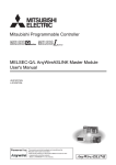
This manual describes the specifications, part names, and settings of the QJ51AW12D2 AnyWire DB A20 master
module (hereafter abbreviated as the QJ51AW12D2) and LJ51AW12D2 AnyWire DB A20 master module (hereafter
abbreviated as the LJ51AW12D2).
This module, a product of the joint development project with Anywire Corporation, allows the AnyWire sensor network
system to be constructed in a MELSEC-Q series or MELSEC-L series programmable controller system.
The AnyWire DB A20 system is a high-speed and highly reliable sensor network system.
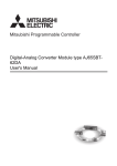
<Features of AnyWire DB A20>
The transmission distance can be selected from 50m/200m/1km/3km using the DIP switch.
Up to 512 remote input points and 512 remote output points can be controlled by one QJ51AW12D2 or LJ51AW12D2
(in the standard setting).
Disconnections can be detected even when the wiring is branched.
AnyWire DB A20 master module
QJ51AW12D2
AnyWire DB A20 master module
LJ51AW12D2
or
AnyWire DB A20
remote I/O module (input)*
AnyWire DB A20
remote I/O module (output)*
AnyWire DB A20
AnyWire DB A20
terminating unit*
*: Manufactured by Anywire Corporation
<Configuration of the AnyWire DB A20 system>
The following table lists the maximum number of connectable modules in one AnyWire DB A20 system.
Module
The maximum number of
connectable modules
Master module
1
Slave module
128
17
Memo
18
CHAPTER 2 SPECIFICATIONS
CHAPTER 2
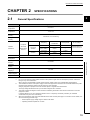
2.1
SPECIFICATIONS
2
General Specifications
Item
Specifications
Operating ambient
0 to 55*4
temperature
Storage ambient
25 to 75
temperature
Operating ambient
humidity
5 to 95%RH, non-condensing
Storage ambient
humidity
Frequency
Compliant
Vibration
with JIS B
resistance
3502 and IEC
61131-2
Shock resistance
Operating
Under
intermittent
vibration
Constant
acceleration
Half amplitude
5 to 8.4Hz
3.5mm
8.4 to 150Hz
9.8m/
Under continuous
5 to 8.4Hz
1.75mm
vibration
8.4 to 150Hz
4.9m/
No. of sweeps
10 times each in X,
Y, and Z directions
Compliant with JIS B 3502 and IEC 61131-2 (147 m/, 3 times each in X, Y, and Z directions)
No corrosive gas
atmosphere
Operating
Installation
2.1 General Specifications
0 to 2000m
altitude*1
Inside the control panel
location
Overvoltage
or less
category*2
Pollution degree*3
2 or less
Equipment class
Class
*1
*2
*3
*4
Do not use or store the programmable controller under pressure higher than the atmospheric pressure at sea level.
Doing so may cause malfunction.
When using the programmable controller under pressure, please consult your local Mitsubishi representative.
This indicates the section of the power supply to which the equipment is assumed to be connected between the public
electrical power distribution network and the machinery within premises.
Category applies to equipment for which electrical power is supplied from fixed facilities.
The surge voltage withstand level for up to the rated voltage of 300 V is 2500 V.
This index indicates the degree to which conductive material is generated in terms of the environment in which the
equipment is used.
In pollution degree 2, only non-conductive pollution occurs. A temporary conductivity caused by an accidental
condensation may also occur occasionally.
When the transmission clock of the QJ51AW12D2 whose serial number (sixth digit) is 5 or earlier is set to 125kHz, use
within the following specified range.
• External power supply voltage range: 21.6VDC to 25.2VDC
• Operating ambient temperature: 0 to 50
19
2.2
Performance Specifications
2.2.1
Performance specifications
Specifications
Item
QJ51AW12D2
LJ51AW12D2
125kHz*3
31.3kHz
7.8kHz
2kHz
125kHz
31.3kHz
7.8kHz
2kHz
50m
200m
1km
3km
50m
200m
1km
3km
Number of connected modules
Up to 128
Up to 128
Up to 128
Up to 32*1
Up to 128
Up to 128
Up to 128
Up to 32*1
Transmission system
Cyclic transmission with full-duplex mode
Connection type
Bus topology (Multidrop system, T-branch system, tree branch system)
Transmission protocol
Dedicated protocol (AnyWire DB A20)
Error control
Double check system
Transmission clock
Maximum transmission distance
(Total length)
Number of connected I/O points
Up to 1024 points (512 input points/512 output points)
(However, up to 1024 input points/1024 output points can be set)*2
Disconnected transmission cable location detection function, transmission cable short detection function,
RAS function
transmission cable power supply voltage drop detection function
• UL-compliant general-purpose 2-/4-wire cable (VCTF, VCT 0.75 to 1.25, rated temperature 70 or
higher)
• UL-compliant general-purpose wire (0.75 to 1.25, rated temperature 70 or higher)
DB A20 transmission cable
• FK4-UL075-100 (AnyWire) (0.75, rated temperature 90) (UL-compliant item)
(Regardless of the type of the transmission cable, when the transmission distance exceeds 200m, use
wires with a diameter of 0.9 to 1.25.)
• UL-compliant general-purpose 2-wire cable (VCTF, VCT 0.75 to 2.0, rated temperature 70 or
24VDC power cable
higher)
• UL-compliant general-purpose wire (0.75 to 2.0, rated temperature 70 or higher)
• FK4-UL075-100 (AnyWire) (0.75, rated temperature 90) (UL-compliant item)
Power supply*3
Number of I/O occupied points
Circuit:
Circuit:
(Supplied from the Q bus side) Voltage +5V5%,
(Supplied from the L bus side) Voltage +5V5%,
Current 0.5A max.
Current 0.2A max.
Transmission cable:
Transmission cable:
Voltage 24VDC +15 to -10% (21.6 to 27.6VDC),
Voltage 24VDC +15 to -10% (21.6 to 27.6VDC),
ripple voltage 0.5Vp-p or lower
ripple voltage 0.5Vp-p or lower
Current 0.5A (When 128 slave modules are
Current 0.5A (When 128 slave modules are
connected and the load current is not included)
connected and the load current is not included)
32 points (I/O assignment: intelligent 32 points)
Number of writes to EEPROM
100000 times (maximum)
External dimensions
98 mm (H) 27.4 mm (W) 100 mm (D)
90mm (H) 28.5mm (W) 104.5mm (D)
Weight
0.11kg
0.2kg
*1
*2
*3
20
Up to 64 modules can be connected within 2km.
Used when required in special situations.
When the transmission clock of the QJ51AW12D2 whose serial number (sixth digit) is 5 or earlier is set to 125kHz, use
within the following specified range.
• External power supply voltage range: 21.6VDC to 25.2VDC
• Operating ambient temperature: 0 to 50
CHAPTER 2 SPECIFICATIONS
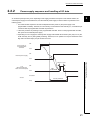
2.2.2
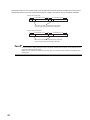
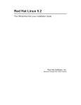
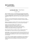
Power supply sequence and handling of I/O data
2
An incorrect input/output may occur depending on the supply procedure of the power of the master module, the
external power supply for transmission line, and the external power supply for slave module. Pay attention to the
following points.
• The master module requires 2 seconds of elapsed time after power-on (the power supply of the
programmable controller). Therefore, do not make any access related to this module (X, Y, or FROM/ TO) for
2 seconds after the programmable controller is powered on.
• Follow the procedure of powering on the programmable controller. Power on the programmable controller,
then power on the external power supply.
• Depending on how to supply the external power supply, D/G terminal disconnection (Xn4) may turn on (the
"ALM" LED may turn on) during initial processing. Therefore, turn on (500ms or more) and off Disconnection
flag reset command output (Yn0) at the start of access.
ON
Power supply of
a programmable
controller
2s or more
OFF
ON
External power supply
OFF
2.2 Performance Specifications
2.2.2 Power supply sequence and handling of I/O data
500ms or more
ON
Yn0
(Disconnection flag
reset command output)
OFF
AND
condition
Execution
Access
Access prohibited
Stop
21
2.3
Applicable System
2.3.1
QJ51AW12D2
(1) Mountable modules and the number of mountable modules
The applicable CPU module, network module, and the number of mountable modules for the QJ51AW12D2 are
shown below.
Insufficient power capacity may occur depending on the combination of other modules and the number of
mountable modules.
When mounting the modules, consider the power capacity.
If the power capacity is insufficient, reconsider the combination of the mounted modules.
Connectable module
Module type
Basic model QCPU
Base unit
Model name
mountability
Q00JCPU
Q00CPU, Q01CPU
High Performance model
Q02CPU, Q02HCPU, Q06HCPU,
QCPU
Q12HCPU, Q25HCPU
Number of
mountable
modules
Up to 8
Up to 24
Up to 64
Q00UJCPU
Up to 8
Q00UCPU, Q01UCPU
Up to 24
Q02UCPU
Up to 36
Q03UDCPU, Q04UDHCPU,
Q06UDHCPU, Q10UDHCPU,
CPU module
Universal model QCPU
Q13UDHCPU, Q20UDHCPU,
Q26UDHCPU
Up to 64
Q03UDECPU, Q04UDEHCPU,
Q06UDEHCPU, Q10UDEHCPU,
Q13UDEHCPU, Q20UDEHCPU,
Q26UDEHCPU, Q50UDEHCPU,
Q100UDEHCPU
Process CPU
Redundant CPU
Q02PHCPU, Q06PHCPU,
Q12PRHCPU, Q25PRHCPU
Q06CCPU-V-B, Q06CCPU-V,
C controller module
Q06CCPU-V-H01, Q12DCCPU-V
Q24DHCCPU-V
Network module
Up to 64
Q12PHCPU, Q25PHCPU
QJ72LP25-25, QJ72LP25G,
QJ72LP25GE, QJ72BR15
Up to 53
Up to 64
Up to 62
Up to 64
: Can be mounted, : Cannot be mounted to the main base unit, can be mounted to the extension base unit
(2) Compatibility with multiple CPU system
The QJ51AW12D2 supports the multiple CPU system from its first product.
When using the QJ51AW12D2 in the multiple CPU system, refer to the following manual.
• QCPU User's Manual (Multiple CPU System)
22
CHAPTER 2 SPECIFICATIONS
2.3.2
LJ51AW12D2
(1) Mountable modules and the number of mountable modules
2
The applicable CPU module, head module, and the number of mountable modules for the LJ51AW12D2 are
shown below.
The number of extension blocks differs depending on the CPU module or the head module to be used.
The head module cannot configure an extension system.
Mountable module
Module type
Model name
Number of
extension
Number of mountable modules*1
blocks
30 modules
L02SCPU,
L02SCPU-P,
L02CPU,
Extension block: 11 modules
L06CPU-P,
L26CPU-P,
• Extension block 1: 10 modules
Main block: 10 modules maximum
L06CPU,
L26CPU,
• Main block: 9 modules
2 blocks maximum
L02CPU-P
CPU module
maximum
3 blocks maximum
*1
*2
40 modules
• Main block: 9 modules
• Extension block 2: 10 modules
• Extension block 3: 11 modules
L26CPU-PBT
LJ72GF15-T2
• Extension block 2: 11 modules
• Extension block 1: 10 modules
L26CPU-BT,
Head module
Maximum configuration*2
Not expandable
10 modules maximum
10 modules maximum
Power supply module, CPU module, display unit, extension module, RS-232 adapter, RS-422/485 adapter, and END
cover are excluded.
Total of mountable I/O modules, intelligent function modules, and network modules.
2.3 Applicable System
2.3.2 LJ51AW12D2
23
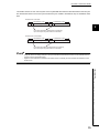
2.4
External Dimensions
4
98
(1) QJ51AW12D2
23
90
10
27.4
(Unit: mm)
24
CHAPTER 2 SPECIFICATIONS
4
(2) LJ51AW12D2
90
45
2
4
4
(45)
DIN rail center
95
104.5
28.5
(Unit: mm)
2.4 External Dimensions
25
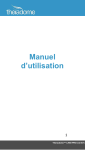
2.5
Part Names
LED indicator
Operation mode selector
SET switch
(automatic address setting switch)
Connector for maintenance
(cannot be used)
Transmission cable
terminal block
For details on each part, refer to the following.
• LED indicator: Page 55, CHAPTER 6
• Operation mode selector: Page 29, Section 3.1
• SET switch: Page 53, Section 5.1
• Transmission cable terminal block: Page 57, CHAPTER 7
26
CHAPTER 2 SPECIFICATIONS
2.6
Module Mounting
For precautions on the installation environment and the installation position of the modules, refer to the following.
2
• User's Manual (Hardware Design, Maintenance and Inspection) for the CPU module used
• MELSEC-L CC-Link IE Field Network Head Module User's Manual
2.6 Module Mounting
27
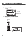
2.7
Checking Function Version and Serial Number
The serial number and function version of the master module can be checked on the rating plate and the front of the
module.
(1) Checking on the rating plate
The rating plate is located on the side of the master module.
• QJ51AW12D2
powered by
MODEL
Serial number
Function version
SERIAL 121013000000000 -B
Relevant regulation
standards
(2) Checking on the front (at the bottom) of the module
The serial number on the rating plate is printed on the front (at the bottom) of the module.
• QJ51AW12D2
Function version
121011000000000-B
Serial number
28
CHAPTER 3 OPERATION MODE
CHAPTER 3
OPERATION MODE
Connect the slave module for the AnyWire DB A20.
3.1
3.1.1
QJ51AW12D2
3
Transmission speed setting
Select the settings such as the transmission distance using the operation mode selector (4-gang DIP switch).
• SW-1, 2 Set the transmission distance using a combination of ON/OFF for 1 and 2.
• SW-3 System reserve (Set the switch to OFF. Using the module with this switch set to ON may cause
malfunction.)
• SW-4 System reserve (Set the switch to OFF. Using the module with this switch set to ON may cause
malfunction.)
Switch
1
2
OFF
OFF
Specifications
2kHz 3km
OFF
ON
7.8kHz 1km
ON
OFF
31.3kHz 200m
ON
ON
125kHz 50m
3.1 QJ51AW12D2
3.1.1 Transmission speed setting
Operation mode selector
To enable the operation mode selector, switch it to the right.
*The default switch setting is OFF.
29
• Switch off the power supply before setting the operation mode.
• Set the operation mode according to the transmission specifications being used.
• If the transmission specifications of the QJ51AW12D2 do not match those of the connected slave module,
transmission cannot be performed correctly, resulting in malfunction.
• The operation mode selector is recessed from the front surface. When setting the switch, use a precision driver
and be careful not to damage any of the internal boards.
30
CHAPTER 3 OPERATION MODE
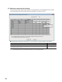
3.1.2
Setting of the number of transmission points, double check
mode, and waveform output method
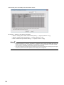
Set the number of transmission points, double check mode, and waveform output method using "Switch 1", "Switch 3
", and "Switch 4" of "Switch setting for I/O and intelligent function module".
Double-click the "PLC Parameter" in the Project window of the programming tool, and perform the following
3
operations.
• Click the "I/O Assignment" tab.
• Click the "Switch Setting" button.
• Open the "Switch Setting for I/O and Intelligent Function Module" window.
• Set a value to "Switch 1", "Switch 3", and "Switch 4".
Double-click this item.
3.1 QJ51AW12D2
3.1.2 Setting of the number of transmission points, double check mode, and waveform output method
"Q Parameter Setting" window
Click this button.
31
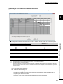
"Switch Setting for I/O and Intelligent Function Module" window
Set "Switch 1", "Switch 3", and "Switch 4" as follows.
• "Switch 1": Setting of the number of transmission points ( Page 33, Section 3.1.2 (1))
• "Switch 3": Double check mode setting ( Page 34, Section 3.1.2 (2))
• Switch 4: Waveform output method setting ( Page 36, Section 3.1.2 (3))
• Be sure to set "Switch 1", "Switch 3", and "Switch 4". Furthermore, set the correct and suitable value for the slot
position of the QJ51AW12D2. If the settings are not configured, or if the setting position or the switch selection
value is incorrect, AnyWire DB A20 transmission does not operate normally.
• If the switch settings are changed using the programming tool, write the parameters and supply the power again
or reset the system. Without these operations, switch settings are not configured.
32
CHAPTER 3 OPERATION MODE
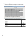
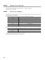
(1) Setting of the number of transmission points
Set the number of transmission points using "Switch 1" of "Switch setting for I/O and intelligent function module".
3
Enter a value from 0 to 9
in this column.
Correspondence between the value from 0 to 9 set for "Switch 1" and the number of connected I/O points
*1
*2
"Switch 1"*1
Input
Output
512
512
0
448
448
1
384
384
2
320
320
3
256
256
4
192
192
5
128
128
6
64
64
7
32
32
8
1024
1024
9*2
The value other than 0 to 9 is reserved by the system. Do not change the settings.
Used when required in special situations.
Transmission also can be made for normal use. However, the address after the "Maximum address setting-Number of
self occupied points" of the slave module for AnyWire DB A20 becomes unassigned, and the transmission cycle time
becomes slower.
For 32-Point Remote I/O Module
Maximum address setting: 510
Number of self occupied points: 32 points
According to the details above, up to 510 to 541 points are used as the maximum address that is
occupied by the remote I/O module.
Addresses of 541 to 1023 points become unassigned, and cannot be assigned.
33
3.1 QJ51AW12D2
3.1.2 Setting of the number of transmission points, double check mode, and waveform output method
Number of connected I/O points
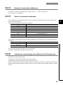
(2) Double check mode setting
Set the double check mode using "Switch 3" of "Switch setting for I/O and intelligent function module".
The QJ51AW12D2 with a serial number where the sixth digit is "6" or later can be set.
Enter a value from 0 to 40
in this column.
Correspondence between the value from 0 to 40 set for "Switch 3" and the double check
Double check
Bit data at all points are double-checked.
0
Word data (16 bits) of the first word are double-checked. At the remaining points, bit data are
double-checked.
Word data (16 bits) of the first two words are double-checked. At the remaining points, bit data are
double-checked.
Word data (16 bits) of the first three words are double-checked. At the remaining points, bit data are
double-checked.
Word data (16 bits) of the first 63 words are double-checked. At the remaining points, bit data are
double-checked.
Word data (16 bits) at all points are double-checked.
*1
34
"Switch 3"*1
The value other than 0 to 40 is reserved by the system. Do not change the settings.
1
2
3
3F
40
CHAPTER 3 OPERATION MODE
The double check is an error control system of the AnyWire DB A20 where the data transmitted in the last cycle
are checked with those in the current cycle and when they are verified to be identical, they are handled as valid
data.
Double check of bit data
Transmission cycle
Bit
N time (previous)
Transmission cycle
Bit
N+1 times (current)
3
If the same bit data is verified twice successively,
input and output are performed as a valid data.
Double check of word data
Transmission cycle
Word
N time (previous)
Transmission cycle
Word
N+1 times (current)
If the same word data is verified twice successively,
input and output are performed as a valid data.
• Using the "Switch 3" setting, data (bit or word) to be double-checked within the frame can be selected from the
head area of the transmission frame.
• Digital I/O slave modules are suitable for bit double check, and analog I/O slave modules are suitable for word
double check.
3.1 QJ51AW12D2
3.1.2 Setting of the number of transmission points, double check mode, and waveform output method
35
(3) Waveform output method setting
Set the waveform output method using "Switch 4" of "Switch setting for I/O and intelligent function module".
The QJ51AW12D2 with a serial number where the sixth digit is "6" or later can be set.
Enter a value from 0, 1
in this column.
Correspondence between the value from 0 to 1 set for "Switch 4" and the waveform output method
Waveform output method
When Module READY (Xn0) turns on, the transmission waveform is output.
When Module READY (Xn0) and Transmission waveform output command (Yn2) turn on, the
transmission waveform is output.
*1
36
The value other than 0 and 1 is reserved by the system. Do not change the settings.
"Switch 4"*1
0
1
CHAPTER 3 OPERATION MODE
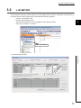
3.2
LJ51AW12D2
Set the operation mode using "Switch setting for I/O and intelligent function module". Double-click "PLC Parameter" in
the Project window of the programming tool, and perform the following operations.
• Click the "I/O Assignment" tab.
• Click the "Switch Setting" button.
3
• Open the "Switch Setting for I/O and Intelligent Function Module" window.
• Set a value to "Switch 1" to "Switch 4".
Double-click this item.
"L Parameter Setting" window
3.2 LJ51AW12D2
Click this button.
37
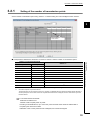
"Switch Setting for I/O and Intelligent Function Module" window
Set "Switch 1" to "Switch 4" as follows.
• "Switch 1": Setting of the number of transmission points ( Page 39, Section 3.2.1)
• "Switch 2": Transmission speed setting ( Page 40, Section 3.2.2)
• "Switch 3": Double check mode setting ( Page 41, Section 3.2.3)
• Switch 4: Waveform output method setting ( Page 43, Section 3.2.4)
• Be sure to set "Switch 1" to "Switch 4". Furthermore, set the correct and suitable value for the slot position of the
LJ51AW12D2. If the settings are not configured, or if the setting position or the switch selection value is incorrect,
the AnyWire DB A20 transmission does not operate normally.
• If the switch settings are changed using the programming tool, write the parameters and supply the power again
or reset the system. Without these operations, switch settings are not configured.
38
CHAPTER 3 OPERATION MODE
3.2.1
Setting of the number of transmission points
Set the number of transmission points using "Switch 1" of "Switch setting for I/O and intelligent function module".
3
Enter a value from 0 to 9
in this column.
Correspondence between the value from 0 to 9 set for "Switch 1" and the number of connected I/O points
*1
*2
3.2 LJ51AW12D2
3.2.1 Setting of the number of transmission points
Number of connected I/O points
"Switch 1"*1
Input
Output
512
512
0
448
448
1
384
384
2
320
320
3
256
256
4
192
192
5
128
128
6
64
64
7
32
32
8
1024
1024
9*2
The value other than 0 to 9 is reserved by the system. Do not change the settings.
Used when required in special situations.
Transmission also can be made for normal use. However, the address after the "Maximum address setting-Number of
self occupied points" of the slave module for AnyWire DB A20 becomes unassigned, and the transmission cycle time
becomes slower.
For 32-Point Remote I/O Module
Maximum set address: 510
Number of self-occupied points: 32 points
According to the details above, up to 510 to 541 points are used as the maximum address that is
occupied by the remote I/O module.
Addresses of 541 to 1023 points become unassigned, and cannot be assigned.
39
3.2.2
Transmission speed setting
Set the transmission speed using "Switch 2" of "Switch setting for I/O and intelligent function module".
Enter a value from 0 to 3
in this column.
Correspondence between the value from 0 to 3 set for "Switch 2" and the transmission speed
*1
40
Transmission speed (transmission distance)
"Switch 2"*1
2kHz 3km
0
7.8kHz 1km
1
31.3kHz 200m
2
125kHz 50m
3
The value other than 0 to 3 is reserved by the system. Do not change the settings.
CHAPTER 3 OPERATION MODE
3.2.3
Double check mode setting
Set the double check mode using "Switch 3" of "Switch setting for I/O and intelligent function module".
3
Enter a value from 0 to 40
in this column.
Correspondence between the value from 0 to 40 set for "Switch 3" and the double check
Bit data at all points are double-checked.
"Switch 3"*1
0
Word data (16 bits) of the first word are double-checked. At the remaining points, bit data are
double-checked.
Word data (16 bits) of the first two words are double-checked. At the remaining points, bit data are
double-checked.
Word data (16 bits) of the first three words are double-checked. At the remaining points, bit data are
double-checked.
Word data (16 bits) of the first 63 words are double-checked. At the remaining points, bit data are
double-checked.
Word data (16 bits) at all points are double-checked.
*1
3.2 LJ51AW12D2
3.2.3 Double check mode setting
Double check
1
2
3
3F
40
The value other than 0 to 40 is reserved by the system. Do not change the settings.
41
The double check is an error control system of the AnyWire DB A20 where the data transmitted in the last cycle are
checked with those in the current cycle and when they are verified to be identical, they are handled as valid data.
Double check of bit data
Transmission cycle
Bit
N time (previous)
Transmission cycle
Bit
N+1 times (current)
If the same bit data is verified twice successively,
input and output are performed as a valid data.
Double check of word data
Transmission cycle
Word
N time (previous)
Transmission cycle
Word
N+1 times (current)
If the same word data is verified twice successively,
input and output are performed as a valid data.
• Using the "Switch 3" setting, data (bit or word) to be double-checked within the frame can be selected from the
head area of the transmission frame.
• Digital I/O slave modules are suitable for bit double check, and analog I/O slave modules are suitable for word
double check.
42
CHAPTER 3 OPERATION MODE
3.2.4
Waveform output method setting
Set the waveform output method using "Switch 4" of "Switch setting for I/O and intelligent function module".
3
Enter 0 and 1 in this
column.
Correspondence between the value from 0 to 1 set for "Switch 4" and the waveform output method
When Module READY (Xn0) turns on, the transmission waveform is output.
When Module READY (Xn0) and Transmission waveform output command (Yn2) turn on, the
transmission waveform is output.
*1
"Switch 4"*1
3.2 LJ51AW12D2
3.2.4 Waveform output method setting
Waveform output method
0
1
The value other than 0 and 1 is reserved by the system. Do not change the settings.
43
CHAPTER 4
PROGRAMMING
This chapter describes programs of the master module.
When applying the program examples introduced in this chapter to the actual system, ensure the applicability and
confirm that it does not cause system control problems.
4.1
I/O Signals with CPU Module
The master module is an intelligent function module. Thirty-two input points and 32 output points are used for the data
communication with the CPU module.
System status information is stored in this area.
The "buffer memory area" is used to input/output the signal to/from the remote I/O module.
4.1.1
I/O signal list
The "n" in the table below is the start I/O number of the master module which is determined according to the
installation position and modules installed before the master module.
If the start I/O number of the master module is "X/Y10"
Xn0 to X(n+1)F X10 to X2F
Yn0 to Y(n+1)F Y10 to Y2F
Input number
Signal name
Output
Xn0
Module READY
Yn0
Xn1
Short between D and G terminals
Yn1
Xn2
Short between D and 24 V terminals
Xn3
24 V not applied
Xn4
D/G line disconnection
Xn5 to Xn7
Use prohibited
"Switch Setting for I/O and Intelligent
Xn8 to XnB
*1
Function Module"
Signal name
number
Yn2*4
Disconnection flag reset command
output
Automatic address detection command
output
Transmission waveform output
command
Yn3
Use prohibited
YnF
Switch 1 setting value*2
XnC to XnF
X(n+1)0 to
X(n+1)3
X(n+1)4*3
X(n+1)5 to
X(n+1)F
*1
*2
*3
*4
44
Use prohibited
Use prohibited
Automatic address detection flag
Y(n+1)0 to
Y(n+1)F
Use prohibited
Use prohibited
Use prohibited for the LJ51AW12D2.
When 8 is set for "Switch 1", the settings are as follows.
Xn8: OFF, Xn9: OFF, XnA: OFF, XnB: ON
Use prohibited for the QJ51AW12D2.
The QJ51AW12D2 with a serial number where the sixth digit is "6" or later can be used.
CHAPTER 4 PROGRAMMING
4.1.2
Details of the input signal
The input signal "Xn0" is the "Module READY" flag, and it turns on while the master module is operating normally.
(It does not turn OFF with Xn1 to Xn4 errors.)
If the input signal is "Xn1 to Xn4", an "Error Flag" that shows the condition of the AnyWire DB A20 transmission cable
turns on.
If normal, the corresponding input signal switches to "OFF", and if an error occurs, it switches to "ON".
Xn1 to Xn3 flags turn "OFF" when the error is removed and then maintain the OFF status.
Xn4 maintains the ON status even when the error is removed.
4
Xn4 turns "OFF" by resetting the power or outputting the signal to Yn0. ( Page 45, Section 4.1.3)
The ON/OFF status is also indicated depending on whether the "ALM" LED is ON or how the "ALM" LED flashes.
Input signal No.
Xn0
Description
Module READY
(Turns OFF when a watchdog timer error occurs)
Normal
Error
ON
OFF
Xn1
Short between D and G terminals
OFF
ON
Xn2
Short between D and 24 V terminals
OFF
ON
24VDC is not being supplied to the master module or the voltage is low.
OFF
ON
OFF
ON
Xn3
Xn4
D/G line disconnection, a slave module error, or power is not being
supplied
For Xn8 to XnB, enter the value set for switch 1 of the "Switch setting for I/O and Intelligent Function Module". Xn8 to
XnB are used to check the settings.
X(n+1)4 turns on when the automatic address detection function is being executed. ( Page 53, Section 5.1)
Details of the output signal
(1) Disconnection flag reset command output
When the output signal Yn0 is turned off and on, provided that the disconnection error has been removed, the
error address information can be cleared by turning off D/G terminal disconnection (Xn4) and resetting the
number of error addresses to "0".
If the error has not been removed, the error flag, the number of the error addresses, and error address are set.
Abnormal address information can also be cleared by supplying the power again.
(2) Automatic address detection command output
Turning the output signal Yn1 from OFF to ON starts the automatic detection of the address. ( Page 52,
CHAPTER 5)
(The "Automatic address detection" function can be also operated using the SET switch.)
(3) Transmission waveform output command
This signal is valid when "Switch 4" of "Switch setting for I/O and intelligent function module" is set to "1".
When the output signal Yn2 is turned off and on, the transmission waveform of the AnyWire DB A20 is output.
45
4.1 I/O Signals with CPU Module
4.1.2 Details of the input signal
4.1.3
4.2
Buffer Memory Area
This area is for data communication between the master module and CPU module.
Buffer memory address
Description
Input (1024 points): The least significant bit of 100H is the 0th data, and the most
100H to 13FH*1
significant bit of 13FH is the 1023rd data.
Output (1024 points): The least significant bit of 1100H is the 0th data, and the most
1100H to 113FH*1
significant bit of 113FH is the 1023rd data.
2000H
Number of error IDs (1 word)
2001H to 2080H
Error ID information
2400H*2
Number of connection IDs (1 word)
2401H to 2480H*2
Connection ID information
2810H*2
Latest error code storage area
2811H*2
Latest error ID storage area
*1
*2
The buffer memory address occupies a 64-word sized area, irrespective of the number of I/O points set for "Switch 1"
setting on Page 31, Section 3.1.2.
The QJ51AW12D2 with a serial number where the sixth digit is "6" or later can be used.
Ex. Correspondence between the buffer memory address and AnyWire DB A20 input address
Buffer memory address
Bit No.
15
14
13
12
11
10
9
8
7
6
5
4
3
2
1
0
100H
15
14
13
12
11
10
9
8
7
6
5
4
3
2
1
0
101H
31
30
29
28
27
26
25
24
23
22
21
20
19
18
17
16
AnyWire input address: 0
46
CHAPTER 4 PROGRAMMING
4.2.1
I/O area
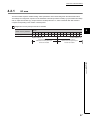
The slave module requires "Address setting" which specifies the start number assigned in the transmission frame.
The settings are configured in 2-point unit. The addresses of both an input slave module (e.g. input remote I/O module)
and an output slave module (e.g. output remote I/O module) start from "0", and the area later than that number is
occupied corresponding to the number of module points.
Ex. Assignment of two 8-point input remote I/O modules
4
Bit No.
Buffer memory address
100H (input)
15
14
13
12
11
10
9
8
7
6
5
4
3
2
1
0
15
14
13
12
11
10
9
8
7
6
5
4
3
2
1
0
AnyWire address: 15
Occupied area by the
address 8 on the 8-point input
remote I/O module
AnyWire address: 0
Occupied area by the
address 0 on the 8-point input
remote I/O module
4.2 Buffer Memory Area
4.2.1 I/O area
47
4.2.2
Number of error addresses
The number of error IDs (addresses) is entered in 2000H. ( Page 52, CHAPTER 5)
Any value from 0 to 128 is entered.
4.2.3
Value of error addresses
If a disconnection or a slave module error is occurred, the error address is written to 2001H to 2080H in the order from
the lowest address up to 128 addresses.
This value is maintained until the disconnection error is reset or until the power is turned off.
Buffer memory address
Description
2001H
Error address 1
2002H
Error address 2
2003H
Error address 3
207FH
Error address 127
2080H
Error address 128
The detected error address is classified and displayed in the memory and on the monitor according to the table below.
Hexadecimal display address
Description
000H to 1FFH
Slave module output address
200H to 3FFH
Slave module input address
The lower 2 digits indicate the address set for the slave module.
The uppermost digit indicates the type of the slave module.
48
CHAPTER 4 PROGRAMMING
4.2.4
Number of connection addresses
The number of connection IDs (addresses) is entered in 2400H. ( Page 52, CHAPTER 5)
Any value from 0 to 128 is entered.
4.2.5
Value of connection addresses
Up to 128 addresses of all the slave modules connected to the master module are written to 2401H to 2480H in the
order from the lowest address.
4
These values are maintained until the power is turned off.
Buffer memory address
Description
2401H
Connection addresses 1
2402H
Connection addresses 2
2403H
Connection addresses 3
247FH
Connection addresses 127
2480H
Connection addresses 128
The detected connection addresses are classified and displayed in the memory and on the monitor according to the
table below.
Description
000H to 1FFH
Slave module output address
200H to 3FFH
Slave module input address
4.2 Buffer Memory Area
4.2.4 Number of connection addresses
Hexadecimal display address
The lower 2 digits indicate the address set for the slave module.
The uppermost digit indicates the type of the slave module.
4.2.6
Latest error code storage area, latest error ID storage area
The latest error code is stored in 2810H.
The latest error code is maintained even after the error is cleared.
The ID (address) of the error code stored in 2810H is stored in 2811H.
However, for Transmission cable power supply voltage drop error (00C8H), D/G short error (00C9H), D/24V short error
(00CBH), Master module hardware error (0064H to 0067H), and CPU module stop error (0068H), 0X0FFFH is entered
in 2811H.
49
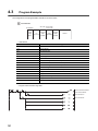
4.3
Program Example
The configuration of the programmable controller is as shown below.
QJ51AW12D2
X0 to XF X10 to X2F
Y10 to Y2F
I/O address
Power
supply
Q62P
CPU
Q06UDHCPU
16-point
input
module
QJ51
AW12D2
16-point
output
module
Vacant
• Used device
Device No.
Application
SM400
Always ON
X10
Module READY
X11
D/G terminal short
X12
D/24V terminal short
X13
24V not applied
X14
D/G line disconnection
Y10
Disconnection flag reset command output
Y11
Automatic address detection command output
M1
Disconnection flag reset command input
M2
Access start flag
M3
Automatic address detection command input
M10
Display of D/G terminal short
M11
Display of D/24V terminal short
M12
Display of 24V not applied
M13
Display of D/G line disconnection
T1
Disconnection flag output ON time (500 ms)
• Program <Disconnection flag clear>
Set the ON time duration
of the Yn0 to 500ms.
Yn0 is turned on.
Yn0 is turned off.
50
CHAPTER 4 PROGRAMMING
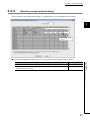
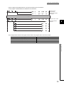
Input is output by the FROM instruction, and output is output by the TO instruction.
A user program is added between the FROM and TO instructions.
Reads inputs to
X100 to X4FF
Reads error address
information
Add a user program here.
Outputs Y100 to Y4FF.
Automatic address
detection
4
The correspondence between each signal and the device in the program above is as shown below.
Signal type
Corresponding device
Input (1024 points)
X100 to X4FF
Output (1024 points)
Y100 to Y4FF
Error address information
D3000 to D3128
4.3 Program Example
51
CHAPTER 5
MONITORING FUNCTION
The AnyWire DB A20 slave module has the specific ID (address). When the master module sends the ID (address),
disconnection and existence of slave modules are detected by receiving a reply from the slave module having the
corresponding ID (address).
The master module uses the automatic address detection operation to store the addresses of the currently connected
slave modules in the EEPROM.
This information is stored even when the power is turned off.
The master module sends the registered addresses in order. If the corresponding slave module does not reply, the
"ALM" LED displays that a disconnection has occurred. Then an error flag is returned to the memory area on the host
side.
Furthermore, this slave module address can be checked.
52
CHAPTER 5 MONITORING FUNCTION
5.1
Automatic Address Detection
Automatic address detection is a function to store the ID (address) of the connected slave module in the EEPROM of
the master module.
In the initial system startup, the ID is not yet registered in the module. Therefore, when the power is on, the "ALM" LED
and the "D/G line disconnection" flag are turned on. ( Page 44, CHAPTER 4, Page 55, CHAPTER 6)
I/O data can be transmitted in this state. However, to use the disconnected branch line detection function, operate
"automatic address detection" at this point.
Operate the automatic address detection in the following situations.
• When starting the system operation after confirming that all the slave modules connected to the master
modules are operating normally
• When adding a slave module after starting the system operation
5
• When removing a slave module after starting the system operation
• When changing the address of a slave module after starting the system operation
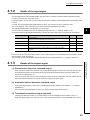
5.1.1
Automatic address detection operation
Use the SET switch or Automatic address detection command output (Yn1) to operate the automatic address
detection.
Using the SET switch
Procedure
Check that all of the slave modules are operating normally.
Keep pressing the SET switch on the master module until the SET
5.1 Automatic Address Detection
5.1.1 Automatic address detection operation
1.
2.
LED (green) turns on.
3.
When the "SET" LED turns on, flashes, and turns off, the ID (address)
has been stored.
Using Automatic address detection command output (Yn1)
Procedure
1.
2.
Check that all of the slave modules are operating normally.
Turn Automatic address detection command output (Yn1) from OFF to
ON. (For details on Automatic address detection command output
(Yn1), refer to Page 44, CHAPTER 4.)
3.
When the "SET" LED turns on, flashes, and turns off, the ID (address)
has been stored.
When an error such as a short occurs in AnyWire DB A20, when the power is turned on, or when the module is reset, the
automatic address detection cannot be operated for approximately 5 seconds.
53
5.2
Monitoring Operation
Registered IDs (addresses) are sent in order. If the slave module does not reply, a disconnection is notified.
The "ALM" LED turns on and the input Xn4 turns on when a disconnection occurs.
This error information is maintained until the power is turned off or until Disconnection flag reset command output
(Yn0) is turned on.
To reset the "ALM" LED lighting and D/G terminal disconnection (Xn4: ON) which are detected during operation, after
removing the cause, reset the power supply of the master module or turn on Disconnection flag reset command output
(Yn0).
The automatic address detection also clears the display and the flag. However, if an unresponding module exists, its ID
(address) is not registered; therefore, it is not monitored.
54
CHAPTER 6 LED DISPLAY
CHAPTER 6
6.1
LED DISPLAY
QJ51AW12D2
Name
Color
LINK
Green
SET
Green
Meaning
Flashing
Module operating status
Off
On
ALM
Red
6
Module failure
During automatic address detection operation
Flashing
During EEPROM write
Off
During normal transmission
On
AnyWire DB A20 D/G line disconnection, or no reply from the slave module
Slow flashing*1
Fast flashing
*2
Off
Short between D and G terminals, short between D and 24V terminals, or the
equivalent status
24VDC is not being supplied, or the supply voltage is too low
During normal transmission
M ERR.
Red
controller. In this case, all functions are stopped.
The error LED for the applicable CPU flashes. (Excluding EEPROM errors)
Off
*1
*2
6.1 QJ51AW12D2
Turns on when an error occurs in the QJ51AW12D2 or the programmable
On
Module normal
"Slow flashing": at approximately one-second intervals
"Fast flashing": at approximately 0.2-second intervals
For details on the display when M ERR. is on, see the table below.
No.
On/Off status
Main Causes
M ERR.
ALM
LINK
SET
1
●
●
●
●
Internal ROM error
2
●
●
●
Internal RAM error
3
●
*3
*3
●
EEPROM error
4
●
Module initialization error
5
●
●
Watchdog timer error
6
●
●
Programmable controller CPU error (ITWDT)
7
●
●
●
Software error (IORSTL)
●:On, :Off
*3
These LEDs turn on, turn off, or flash according to the operating status.
No.1 to 4 are checked only at the time of the reset.
Transmission is performed only when an EEPROM error occurs.
55
6.2
LJ51AW12D2
Name
Color
RUN LED
Green
LINK LED
Green
SET LED
Green
Meaning
On
Operating normally
Off
Master module error, 5VDC power off, CPU module stop error
Flashing
Data link can be performed.
Off, on
Data link cannot be performed.
On
During automatic address detection operation
Off
Operating normally
Flashing
During EEPROM write
On
ALM LED
125K
LED
31.3K
CLOCK
LED
*1
*2
56
LED
Red
Green
Green
7.8K LED
Green
2.0K LED
Green
Slow flashing
D/G disconnection, no response from the slave module
*1
Fast flashing*2
D/24V or D/G short
24VDC is not being supplied, or the voltage is low
Off
Operating normally
On
Transmission speed of 125kHz, operating in the 50m mode
Off
Transmission speed of 125kHz, not in the 50m mode
On
Transmission speed of 31.3kHz, operating in the 200m mode
Off
Transmission speed of 31.3kHz, not in the 200m mode
On
Transmission speed of 7.8kHz, operating in the 1km mode
Off
Transmission speed of 7.8kHz, not in the 1km mode
On
Transmission speed of 2.0kHz, operating in the 3km mode
Off
Transmission speed of 2.0kHz, not in the 3km mode
"Slow flashing": at approximately one-second intervals
"Fast flashing": at approximately 0.2-second intervals
CHAPTER 7 CONNECTIONS
CHAPTER 7
CONNECTIONS
The connection terminals (transmission cable terminal block) for the AnyWire DB A20 transmission cable can be
connected and disconnected easily.
The transmission cables and power supply cables are connected using the common terminal block.
For compliance with the EMC and Low Voltage Directives, refer to Page 73, Appendix 1.
Even when the compliance with the EMC and Low Voltage Directives is not required, use of an EMC-compliant configuration
may reduce the influence from external noise.
7.1
Description of Terminals
Terminal
Description
D
AnyWire DB A20 transmission signal terminal for the master module
G
Connect to the D and G terminals to those on the slave module and terminating unit.
7
D: Transmission cable (+), G: Transmission cable (-)
24V
Power supply terminal for driving the transmission circuit for the master module Connect a 24VDC stabilized
0V
power supply to the 24V and 0V terminals.
Connect the LG terminal to the neutral point of the noise filter inserted between the 24V and 0V terminals.
LG
If malfunctions occur due to the power noise in the 24VDC system, ground the LG terminal with the functional
ground terminal (FG terminal) on the programmable controller at a single point.
manuals of each product.
Transmission cable
terminal block
Transmission cable
terminal block
Fixing screws
Fixing screws
57
7.1 Description of Terminals
For details on connections to the D and G terminals on the slave module and terminating unit, refer to the relevant
7.2
Transmission Cable Terminal Block
Manufacturer: Phoenix Contact Co., Ltd. (Contact: www.phoenixcontact.com)
Model: MSTB2,5/5-STF-5,08AU
Tightening torque: 0.2 to 0.3 Nm
To tighten the connector, a flathead screwdriver having a tipped size of 0.4 2.5mm is required.
Before removing the transmission cable terminal block, check that the fixing screws on both sides are completely
loosened (removed from the socket).
Pulling with excessive force while the screws are still tightened may cause damage to the devices.
Before tightening the terminal block, check that there are no short-circuits due to the disconnected or frayed wires and
tighten the screws at both ends securely. (Tightening torque: 0.2 to 0.3Nm)
58
CHAPTER 7 CONNECTIONS
7.3
Cable Processing
Bare cables can be connected to the transmission cable terminal block; however, for safety reasons, it is
recommended to connect the crimped bar terminals.
For wiring, use the connection cables as listed in Page 20, Section 2.2.1 and tighten them with the applicable
tightening torque.
Use UL-listed solderless terminals and, for processing, use a tool recommended by their manufacturer.
[Recommended bar terminals (manufactured by Phoenix Contact Co., Ltd.)]
• For processing a 0.75 wire: AI 0,75-8 GY
• For processing a 1.25 wire: AI 1,5-8 BK
• For processing a 2 wire: AI 2,5-8 BU or others
• For processing two 0.75 wires: AI-TWIN 2 0,75-8 GY
• For processing two 1.25 wires: AI-TWIN 2 1,5-8 BK
When connecting two wires to one terminal, connect the two wires together to the TWIN bar terminal.
When TWIN bar terminals are used for this transmission cable terminal block, the maximum wire diameter is 1.25.
For details on sizes other than those listed above and crimping tools, refer to the catalog or website of Phoenix Contact
7
Co., Ltd.
● Do not run multiple transmission cables (D, G) using a multicore cable.
7.3 Cable Processing
D
G
D
G
D
G
D
G
● Use the following line diameters for the transmission cables.
200m or shorter: 0.75 to 1.25
200m or longer: 0.9 to 1.25
● The voltage should not fall below the lower limit of the allowable voltage range due to the voltage drop caused by the
cable.
If the voltage falls below the lower limit, malfunctions may occur.
If the voltage falls substantially, install the external power supply.
For installing the external power supply, refer to the "AnyWire DB A20 Series Technical Manual" (manufactured by
Anywire Corporation).
● Do not connect soldered cables directly to the terminals. Doing so may loosen the screws, resulting in a poor contact.
59
7.4
Terminating Unit
To ensure more stable transmission quality, connect a terminating unit (AT2 manufactured by Anywire Corporation) to
the end of the transmission line.
Terminating unit connection
Basic
Important
Connect a terminating unit at the end of a line for one
master module.
Transmission distance 50m (total length)
200m (total length)
1km (total length)
3km (total length)
The setting applies to all the transmission speeds.
Branch of transmission cables (transmission distance: 1km)
Example
AnyWire
at the end
Branch line:
200m
Main line: 500m
Branch line: 300m
Important
Connect one terminating unit at the end of a branch line that
exceeds 200m.
Contact us if more than two branch lines exceed 200m.
Total length
Basic
A
B
The total length of the transmission distance for the AnyWire DB A20 can be
calculated from A + B. Note that the total length should not exceed the maximum
transmission distance set for the system to branch lines.
60
CHAPTER 8 TRANSMISSION TIME
CHAPTER 8
TRANSMISSION TIME
This section describes the transmission cycle time and transmission delay time of AnyWire DB A20.
8.1
Transmission Cycle Time
The transmission cycle time is the time required for the master module and all the slave modules to update I/O data.
8.1.1
Transmission cycle time of the master module
The transmission cycle time of the master module is listed in the table below.
Maximum number of
transmission points setting
Transmission cycle time (ms)
125kHz
31.3kHz
7.8kHz
2kHz
(50m)
(200m)
(1km)
(3km)
0.42
1.7
6.8
24.8
0.7
2.7
10.9
40.7
256 points (128 points 2)
1.2
4.8
19.1
72.4
384 points (192 points 2)
1.7
6.8
27.3
104.2
512 points (256 points 2)
2.2
8.9
35.5
135.9
640 points (320 points 2)
2.7
10.9
43.6
167.6
768 points (384 points 2)
3.2
13.0
51.8
199.4
896 points (448 points 2)
3.8
15.0
60.0
231.1
1024 points (512 points 2)
4.3
17.1
68.2
262.9
2048 points (1024 points 2)
8.4
33.4
133.8
516.8
8
8.1 Transmission Cycle Time
8.1.1 Transmission cycle time of the master module
64 points (32 points 2)
128 points (64 points 2)
61
8.1.2
Effects of the double check system
(1) Input
On the master module side, if the same data is not repeated twice in continuance, the input area data is not
updated (double check). Therefore, a minimum of one transmission cycle time and a maximum of two
transmission cycle times are required for the data response time.
Therefore, signals of two-transmission cycle time or less may not be captured depending on the timing.
To ensure the response to the input signal, provide an input signal that is longer than two-transmission cycle time.
Sampling timing
Minimum data
response time
Minimum of one transmission cycle time
Input data change
Sampling timing
Maximum data
response time
Sampling timing
Input data update
Sampling timing
Sampling timing
Maximum of two transmission cycle times
Input data change
Input data update
(2) Output
As the double check is performed on the slave module side, the time required is the same as that for input,
namely a minimum of one-transmission cycle time and a maximum of two-transmission cycle time.
62
CHAPTER 8 TRANSMISSION TIME
8.2
Transmission Delay Time
This section describes the transmission delay time (time until data is transmitted).
8.2.1
Slave module (input) to master module
The figure below shows the time between a signal input to the slave module and the CPU module device (X) turning
on/off.
Input
Slave module
Master module
1) Signal delay time on the slave module
2) One to 2 transmission cycle
times
3) Processing time on the
master module side
CPU module
4) Sequence program scan
time
8
[Calculation formula]
1) Signal delay time of the slave module + 2) Transmission cycle time 2 + 3) Processing time on the master module
8.2 Transmission Delay Time
8.2.1 Slave module (input) to master module
side + 4) Sequence program scan time 2 [ms]
[Calculation example]
1) Signal delay time of the slave module
Signal delay time of the slave module is 0.17ms: 0.17 [ms]
2) Transmission cycle time 2
When the transmission point is set to 1024 and the transmission speed is set to 31.3kHz: 17.1 2 = 34.2 [ms]
3) Processing time on the master module side
Processing time on the master module side = Transmission speed clock width 16
When the transmission speed is set to 31.3kHz: (1 31.3k) 16 = 0.511 [ms]
4)Sequence program scan time 2
Set the sequence program scan time to 5ms: 5 2 = 10 [ms]
Therefore, the transmission delay time is 0.17 + 34.2 + 0.511 + 10 = 44.88 [ms].
63
8.2.2
Master module to slave module (output)
The figure below shows the time between the CPU module device (Y) turning on/off and a signal output from the slave
module turning on/off.
Output
Slave module
4) Signal delay time on the slave module
3) One to 2 transmission cycle
times
Master module
2) Processing time on the
master module side
CPU module
1) Sequence program scan
time
[Calculation formula]
1) Sequence program scan time + 2) Processing time on the master module side + 3) Transmission cycle time 2 + 4)
Signal delay time of the slave module [ms]
[Calculation example]
1) Sequence program scan time
Set the sequence program scan time to 5ms: 5 [ms]
2) Processing time on the master module side
Processing time on the master module side = Transmission speed clock width 16
When the transmission speed is set to 31.3kHz: (1 31.3k) 16 = 0.511 [ms]
3) Transmission cycle time 2
When the transmission point is set to 1024 and the transmission speed is set to 31.3kHz: 17.1 2 = 34.2 [ms]
4) Signal delay time of the slave module
Signal delay time of the slave module is 0.01ms: 0.01 [ms]
Therefore, the transmission delay time is 5 + 0.511 + 34.2 + 0.01 = 39.72 [ms].
64
CHAPTER 9 TROUBLESHOOTING
CHAPTER 9
TROUBLESHOOTING
9
If the transmission does not start normally, check the following items and perform the troubleshooting.
• All devices are being supplied with 24VDC power supply.
• The "LINK" LEDs of all the AnyWire DB A20 slave modules are flashing.
• The address settings are correct and unique.
For details on the entire AnyWire DB A20 system, refer to the "AnyWire DB A20 Series Technical Manual"
(manufactured by Anywire Corporation).
9.1
Visual Inspection
Check that the communication cables and wires are not disconnected and check the following items.
(1) Checking the LED status of the master module
Errors regarding the operating status and communications of the master module can be checked with the
following LEDs. When the LEDs are in the following status, settings and wiring need to be corrected.
(a) QJ51AW12D2
1.
Check the M.ERR LED of the master module.
If the M ERR. LED is on, perform the following troubleshooting.
Page 68, Section 9.3.1 (1)
Check the LINK LED of the master module.
9.1 Visual Inspection
2.
If the LINK LED does not flash, perform the following troubleshooting.
Page 68, Section 9.3.1 (2)
3.
Check the ALM LED of the master module.
If the ALM LED is flashing at 0.2-second intervals, perform the following troubleshooting.
Page 68, Section 9.3.1 (3)
If the ALM LED is flashing at 1 second intervals, perform the following troubleshooting.
Page 68, Section 9.3.1 (4)
If the ALM LED is on, perform the following troubleshooting.
Page 69, Section 9.3.1 (5)
65
(b) LJ51AW12D2
1.
Check the LINK LED of the master module.
If the LINK LED does not turn on or flash even after power-on, perform the following troubleshooting.
Page 69, Section 9.3.2 (1)
If the LINK LED does not flash, perform the following troubleshooting.
Page 69, Section 9.3.2 (2)
2.
Check the ALM LED of the master module.
If the ALM LED is flashing at 0.2-second intervals, perform the following troubleshooting.
Page 69, Section 9.3.2 (3)
If the ALM LED is flashing at 1 second intervals, perform the following troubleshooting.
Page 70, Section 9.3.2 (4)
If the ALM LED is on, perform the following troubleshooting.
Page 70, Section 9.3.2 (5)
3.
Check the RUN LED of the master module.
If the RUN LED does not turn on, perform the following troubleshooting.
Page 70, Section 9.3.2 (6)
(2) Checking the status of the slave module
Check that there is no error in the slave module.
For the troubleshooting of the slave module, refer to the following.
Page 71, Section 9.4
• When the data (I/O data and parameter data) of the slave module cannot be checked
• When the data (I/O data and parameter data) of the slave module data is unstable
66
CHAPTER 9 TROUBLESHOOTING
9.2
Check with Input Signals
9
(1) If D/G terminal short (Xn1) is on
If D/G terminal short (Xn1) is on, perform the following troubleshooting.
• QJ51AW12D2 ( Page 68, Section 9.3.1 (4))
• LJ51AW12D2 ( Page 70, Section 9.3.2 (4))
(2) If D/24V terminal short (Xn2) is on
If D/24V terminal short (Xn2) is on, perform the following troubleshooting.
• QJ51AW12D2 ( Page 68, Section 9.3.1 (4))
• LJ51AW12D2 ( Page 70, Section 9.3.2 (4))
(3) If 24V not applied (Xn3) is on
If 24V not applied (Xn3) is on, perform the following troubleshooting.
• QJ51AW12D2 ( Page 68, Section 9.3.1 (3))
• LJ51AW12D2 ( Page 69, Section 9.3.2 (3))
(4) If D/G terminal disconnection (Xn4) is on
If D/G terminal disconnection (Xn4) is on, perform the following troubleshooting.
• QJ51AW12D2 ( Page 69, Section 9.3.1 (5))
• LJ51AW12D2 ( Page 70, Section 9.3.2 (5))
9.2 Check with Input Signals
67
9.3
Troubleshooting of Master Module
This section describes the troubleshooting of the master module.
9.3.1
QJ51AW12D2
(1) The M ERR. LED on the master module is on.
Item
Action
Check that the supply power to the
programmable controller system is
within the specifications.
Check that a hardware failure or a
watchdog timer error has not
If the M ERR. LED does not turn off after powering on the master module, hardware
failure may have occurred.
Please consult your local Mitsubishi representative.
occurred.
(2) The LINK LED on the master module does not flash.
Item
Action
A malfunction has been detected in the master module hardware.
Check that the LINK LED is off.
Reset the master module.
If the error occurs again, the module may be in failure. Please consult your local
Mitsubishi representative.
(3) The ALM LED on the master module is flashing at 0.2 second intervals.
Item
Action
Check the power supply voltage of
Adjust the power supply voltage of the external power supply which is connected to
the external power supply.
the master module to be within the rated value (21.6 to 27.6VDC).
Check that the power cables are not
Check that the power cables (24V, 0V) are not disconnected or short-circuited.
short-circuited.
When crimping the link connector, check that the pin assignment is correct.
Check the wiring of the terminal
blocks.
Check that the external power supply is properly connected to the terminal block of
the master module or the slave module. Check that there is no short-circuit or
incorrect wiring and screws are tightened sufficiently.
(4) The ALM LED on the master module is flashing at 1 second intervals.
Item
Check that the signal wire of the
transmission cable (D-G or D-24V) is
not short-circuited.
Check the wiring of the terminal
blocks.
68
Action
Check that the transmission cables are not short-circuited. When crimping the link
connector, check that the pin assignment is correct.
Check that the transmission cables are not in contact with each other and that there
is no incorrect wiring in the terminal block wiring of the master module and the slave
module.
CHAPTER 9 TROUBLESHOOTING
9
(5) The ALM LED on the master module is on.
Item
Action
Check that the signal wire of
Check that the transmission cables (entire cables) are free from disconnection. Also
transmission cable (D or G) is not
check that the cables have been crimped with proper pin assignment using link
short-circuited.
connectors appropriate to the wire diameter.
Check that the signal cables are properly connected to the terminal block of the
Check the wiring of terminal blocks.
master module. In addition, check that there is no incorrect wiring and that screws
are tightened sufficiently.
When creating a new system, adding or removing a slave module, or changing the
Perform the automatic address
detection operation.
address of the slave module, perform the automatic address detection operation.
After the operation ends, check that the number of slave modules and the address
are consistent with those of the actual system.
Check the existence of the slave
module.
9.3.2
If the LINK LED of the slave module does not flash, check that there is no
disconnection, short-circuit, incorrect wiring, or poor contact in the transmission
cables around the module.
LJ51AW12D2
(1) When the LINK LED does not turn on or flash after power-on
Item
Check the power supply voltage.
Action
Check that the power supply voltage of the external power supply is within the rated
value.
Check that the external power supply is properly connected to the terminal block of
the master module.
blocks.
Check that there is no short-circuit or incorrect wiring and screws are tightened
sufficiently.
Check that the power cables are not
Check that the power cables (24V, 0V) are not disconnected or short-circuited.
short-circuited.
When crimping the link connector, check that the pin assignment is correct.
Check the total internal current
Review the system configuration so that the total internal current consumption does
consumption of the entire system.
not exceed the rated output current of the power supply module.
(2) The LINK LED on the master module does not flash.
Item
Action
A malfunction has been detected in the master module hardware.
Check that the LINK LED is turned
Reset the master module.
on.
If the error occurs again, the module may be in failure. Please consult your local
Mitsubishi representative.
(3) The ALM LED on the master module is flashing at 0.2 second intervals.
Item
Action
Check the power supply voltage of
Adjust the power supply voltage of the external power supply which is connected to
the external power supply.
the master module to be within the rated value (21.6 to 27.6VDC).
Check that the power cables are not
Check that the power cables (24V, 0V) are not disconnected or short-circuited.
short-circuited.
When crimping the link connector, check that the pin assignment is correct.
Check the wiring of the terminal
blocks.
Check that the external power supply is properly connected to the terminal block of
the master module or the slave module. Check that there is no short-circuit or
incorrect wiring and screws are tightened sufficiently.
69
9.3 Troubleshooting of Master Module
9.3.2 LJ51AW12D2
Check the wiring of the terminal
(4) The ALM LED on the master module is flashing at 1 second intervals.
Item
Check that the signal wire of the
transmission cable (D-G or D-24V) is
not short-circuited.
Check the wiring of the terminal
blocks.
Action
Check that the transmission cables are not short-circuited. When crimping the link
connector, check that the pin assignment is correct.
Check that the transmission cables are not in contact with each other and that there
is no incorrect wiring in the terminal block wiring of the master module and the slave
module.
(5) The ALM LED on the master module is on.
Item
Action
Check that the signal wire of
Check that the transmission cables (entire cables) are free from disconnection. Also
transmission cable (D or G) is not
check that the cables have been crimped with proper pin assignment using link
short-circuited.
connectors appropriate to the wire diameter.
Check that the signal cables are properly connected to the terminal block of the
Check the wiring of terminal blocks.
master module. In addition, check that there is no incorrect wiring and that screws
are tightened sufficiently.
When creating a new system, adding or removing a slave module, or changing the
Perform the automatic address
address of the slave module, perform the automatic address detection operation.
detection operation.
After the operation ends, check that the number of slave modules and the address
are consistent with those of the actual system.
Check the existence of the slave
module.
If the LINK LED of the slave module does not flash, check that there is no
disconnection, short-circuit, incorrect wiring, or poor contact in the transmission
cables around the module.
(6) The RUN LED on the master module does not turn on.
Item
Action
Check that the supply power to the
programmable controller system is
within the specifications.
Check that a hardware failure or a
watchdog timer error has not
occurred.
70
If the RUN LED does not turn on after powering on the master module, hardware
failure may have occurred.
Please consult your local Mitsubishi representative.
CHAPTER 9 TROUBLESHOOTING
9.4
Troubleshooting of Slave Module
9
This section describes the troubleshooting of the slave module.
(1) When I/O data and parameter data cannot be checked
Item
Action
• Check that the buffer memory map of the programmable controller device and the
Check the FROM/TO instruction
issued by the program using the
programming tool.
master module assigned by the MOV instruction or the FROM/TO instruction is
appropriate.
• Check that the programmable controller CPU is in the STOP state. Slave module
cannot output when the programmable controller CPU is in the STOP state.
If the LINK LED of the slave module does not flash, check that there is no
Check that the LINK LED on the
slave module is flashing.
disconnection, short-circuit, incorrect wiring, or poor contact in the transmission
cables around the module.
In addition, check that the transmission speed setting of the slave module is same
as that of the master module.
If the RDY LED on the slave module does not turn on, a power supply error has
Check that the RDY LED on the slave
module is on.
occurred.
Possible causes are disconnection of the power cable, short-circuit, and shortage of
the power supply voltage.
Check the wiring, installation method, and power supply voltage of the slave module.
(2) When the I/O data and parameter data of the slave module is unstable
Item
Check the connection of the
Pay attention to the polarities of the terminating unit (AT2) and connect it correctly.
Check the total length of the
Adjust the total length of the AnyWire DB A20 system to be within the specification
transmission cables.
range.
Check the type of the transmission
cables.
Check that the transmission cables have the specified type, wire diameter, and
tightening torque to the terminal block. Do not run multiple transmission cables (D,
G) using a multicore cable.
Check the voltage range of the
Adjust the power supply voltage of the external power supply to be within the rated
external power supply.
value (21.6 to 27.6VDC).
Check that the slave module does not
have the same address as the
Set a unique address in the slave module.
addresses of other slave modules.
Check the FROM/TO instruction
Check that the buffer memory map of the programmable controller device and the
issued by the program using the
master module assigned by the MOV instruction or the FROM/TO instruction is
programming tool.
appropriate.
71
9.4 Troubleshooting of Slave Module
terminating unit.
Action
9.5
List of Error Codes
This section lists the error codes of the master module.
Error code
Error description
0064H to 0067H
0068H
Master module hardware
error
CPU module stop error
Action
A malfunction has been detected in the master module hardware. Reset the CPU module.
If the error occurs again, the master module may be in failure. Please consult your local
Mitsubishi representative.
A stop error has occurred in the CPU module.
Check and correct the error using PLC Diagnostics of the programming tool.
The voltage of the 24VDC external power supply may be lacking. Perform the following.
• Adjust the power supply voltage of the 24VDC external power supply to be within the
rated value (21.6 to 27.6VDC).
00C8H
Transmission cable
voltage drop error
• Check that the power cables (24V, 0V) are not disconnected or short-circuited. When
crimping the link connector, check that the pin assignment is correct.
• Check that the 24VDC external power supply is properly connected to the terminal block
of the master module or the slave module.
• Check that there is no short-circuit or incorrect wiring and screws are tightened
sufficiently.
The transmission cables (D, G) may have short-circuited. Perform the following.
• Check that the transmission cables (D, G) are not short-circuited. When crimping the link
00C9H
Short between D and G
terminals
connector, check that the pin assignment is correct.
• Check that the transmission cables (D, G) are not in contact with each other and that
there is no incorrect wiring in the terminal block wiring of the master module and the slave
module.
The transmission cables (D, G) may have been disconnected or there may be no response
from the slave module. The slave module may be malfunctioning or the system
configuration may have been changed after the automatic address detection function is
executed. Check Number of the error IDs (Un\G8192) and Error ID information storage area
(Un\G8193 to Un\G8320) of the buffer memory to locate the disconnected cable and
perform the following.
• Check that the transmission cables (entire cables) are free from disconnection. Also
check that the cables have been crimped with proper pin assignment using link
connectors appropriate to the wire diameter.
00CAH
D, G disconnection error
• Check that the signal cables are properly connected to the terminal block of the master
module. In addition, check that there is no incorrect wiring and that screws are tightened
sufficiently.
• When creating a new system, adding or removing a slave module, or changing the
address of the slave module, perform the automatic address detection function. After
executing the automatic address detection function, check that the number of slave
modules and the address are consistent with those of the actual system.
• If the LINK LED on the slave module does not flash, check that there is no disconnection,
short-circuit, incorrect wiring, or poor contact in the transmission cables (D, G) around the
module.
The transmission cables (D, 24V) may have short-circuited. Perform the following.
• Check that the transmission cables (D, 24V) are not short-circuited. When crimping the
00CBH
D-24 V short error
link connector, check that the pin assignment is correct.
• Check that the transmission cables (D, 24V) are not in contact with each other and that
there is no incorrect wiring in the terminal block wiring of the master module and the slave
module.
Check the error information with Latest error code storage area (2810H) and Latest error ID storage area (2811H) of the
buffer memory.
72
APPENDICES
APPENDICES
Appendix 1
A
EMC and Low Voltage Directives
Compliance with the EMC Directive, which is one of the EU directives, has been mandatory for the products sold within
EU member states since 1996 as well as compliance with the Low Voltage Directive since 1997.
To prove the compliance with these Directives, manufacturers must issue an EC Declaration of Conformity and the
products must bear a CE marking.
(1) Sales representative in EU member states
The sales representative in EU member states will be:
Name: Mitsubishi Electric Europe BV
Address: Gothaer Strasse 8, 40880 Ratingen, Germany
Appendix 1.1
Requirements for compliance with the EMC
Directive
The EMC Directive sets two requirements for compliance: emission (conducted and radiated electromagnetic energy
emitted by a product) and immunity (the ability of a product to function without being influenced by externally
generated electromagnetic energy), and all applicable products are required to satisfy these requirements. This
section summarizes the precautions for machinery constructed with this product to comply with the EMC Directive.
do not guarantee that the entire machinery constructed according to the descriptions complies with the EMC Directive.
The manufacturer of the machinery must determine the testing method for compliance and declare conformity to the
EMC Directive.
73
Appendix 1 EMC and Low Voltage Directives
Appendix 1.1 Requirements for compliance with the EMC Directive
These precautions are based on the requirements of the EMC Directive and the harmonized standards. However, they
(1) Installation in control panel
This open-type device is intended to be placed in an industrial control panel or similar type of enclosure.*1
This ensures safety as well as effective shielding of electromagnetic noise emitted from this product.
*1
Modules on the remote station in each network must be also installed inside the control panel.
However, waterproof modules on the remote station can be installed outside the control panel.
(a) Control panel
• Use a conductive control panel.
• Mask off the area used for grounding when securing the top or bottom plate to the control panel using
bolts.
• To ensure electrical contact between the inner plate and the control panel, mask off the bolt installation
areas of an inner plate so that conductivity can be ensured in the largest possible area.
• Ground the control panel with a thick ground cable so that low impedance can be ensured even at high
frequencies.
• Keep the diameter of the holes in the control panel 10cm or less. If the diameter is larger than 10cm,
electromagnetic wave may be emitted. In addition, because electromagnetic wave leaks through a
clearance between the control panel and its door, reduce the clearance as much as possible. The leakage
of radio waves can be suppressed by the direct application of an EMI gasket on the paint surface.
The tests by Mitsubishi were conducted using a panel having the damping characteristics of 37dB (maximum)
and 30db (average) (measured at 3m distance, 30 to 300MHz).
(b) Wiring power and ground cables
Run the ground cable and the power cable of this product as instructed below.
• Provide a ground point to the control panel near the power supply module. Ground the LG (line ground)
and FG (frame ground) terminals of the power supply module for the programmable controller and the LG
terminal of the transmission cable terminal block to the ground point with the thickest and shortest ground
cable possible (about 30cm or shorter). Because the LG and FG terminals serve to dissipate noise
generated within the programmable controller to the ground, the impedance of the ground cable must be
as low as possible. In addition, the ground cable must be kept as short as possible. The ground cable
serves to dissipate noise. Because the ground cable itself bear noise, keeping the cable short means that
the cable prevents itself from being an antenna.
• The ground cable run from the contact point must be twisted with the power cable. By twisting the power
cable with the ground cable, more noise flowing through the power cable can be dissipated to the ground.
However, when a noise filter is attached to the power cable, twisting with the ground cable may be
unnecessary.
74
APPENDICES
A
(2) Cables
(a) Cable connected to the transmission cable terminal block
For the cable connected to the transmission cable terminal block, attach a ferrite core having the attenuation
characteristics equivalent to that of ZCAT3035-1330 made by TDK Corporation as close to the transmission
cable terminal block of this product as possible. Use a ferrite core with three turns of wire as shown below.
(b) Power cable for the 24VDC power supply terminal
Use a CE-marked DC power supply. The DC power supply must be placed together with the module in the
same control panel, and the power cable connected to the power terminal of this product should be 30cm or
shorter.
(3) External power supply
Use a CE-marked external power supply and ground the FG terminal.
(External power supply used for the tests conducted by Mitsubishi: PS5R-SF24 made by IDEC Corporation)
(4) Power supply module for the programmable controller
Ground the LG and FG terminals after short-circuiting them.
Use this product in Zone B*1.
*1
Zone means a category determined according to the industrial environment conditions and defined by the harmonized
standard EN61131-2 of the EMC and Low Voltage Directives.
Zone C: Main power supply insulated from the public power supply by a special transformer
Zone B: Special power supply with the secondary surge protector from the main power (Rated voltage is assumed to be
300V or less.)
Zone A: Local power supply protected by an AC-DC converter or an insulating transformer from the special power
supply (Rated voltage is assumed to be 120V or less.)
Appendix 1.2
Requirements for compliance with the Low Voltage
Directive
The Low Voltage Directive does not apply to this product because it operates on 5VDC and 24VDC power supply.
For making the PLC system used comply with the Low Voltage Directive, refer to the manual supplied with the CPU
module, the base unit, or the head module.
75
Appendix 1 EMC and Low Voltage Directives
Appendix 1.2 Requirements for compliance with the Low Voltage Directive
(5) Installation environment
Appendix 2
Differences between the QJ51AW12D2 and
LJ51AW12D2
This section describes the differences between the QJ51AW12D2 and LJ51AW12D2.
Difference
Item
QJ51AW12D2
LJ51AW12D2
Error diagnostics using system monitor of the
programming tool
Disabled
Enabled
Operation at recovery from error
(24V power supply drop, short circuit of signal
cables)
Error flags are automatically cleared.
Error clear is not required after recovery from error.
Error flags are maintained.
Error clear is required after recovery from error.
76
APPENDICES
Appendix 3
Functions Added and Modified with Version
Upgrade
A
The master module has some new functions added and specifications modified as a result of a version upgrade.
The functions and specifications that can be used in the master module vary depending on the function version and
the serial number.
Supported
Additional functions
Module
function
version
• Double check mode, waveform output method ( Page 31, Section 3.1.2)
• Addition of buffer memory area ( Page 46, Section 4.2)
QJ51AW12D2
B
Sixth digit of the
serial number
"6" or later
Appendix 3 Functions Added and Modified with Version Upgrade
77
REVISIONS
*The manual number is given on the bottom left of the back cover.
Print date
*Manual number
Revision
February 2011
SH(NA)-080968ENG-A
First edition
May 2011
SH(NA)-080968ENG-B
Revision due to error correction
March 2013
SH(NA)-080968ENG-C
October 2014
SH(NA)-080968ENG-D
Revision due to compliance with EMC and UL/cUL
Revision due to the addition of the LJ51AW12D2 and function for the QJ51AW12D2, and
compliance with UL/cUL of the LJ51AW12D2
Japanese manual version SH-080967-E
This manual confers no industrial property rights or any rights of any other kind, nor does it confer any patent licenses. Mitsubishi Electric
Corporation cannot be held responsible for any problems involving industrial property rights which may occur as a result of using the
contents noted in this manual.
2011 MITSUBISHI ELECTRIC CORPORATION
78
WARRANTY
Please confirm the following product warranty details before using this product.
1. Gratis Warranty Term and Gratis Warranty Range
If any faults or defects (hereinafter "Failure") found to be the responsibility of Mitsubishi occurs during use of the product
within the gratis warranty term, the product shall be repaired at no cost via the sales representative or Mitsubishi Service
Company.
However, if repairs are required onsite at domestic or overseas location, expenses to send an engineer will be solely at
the customer's discretion. Mitsubishi shall not be held responsible for any re-commissioning, maintenance, or testing
on-site that involves replacement of the failed module.
[Gratis Warranty Term]
The gratis warranty term of the product shall be for one year after the date of purchase or delivery to a designated place.
Note that after manufacture and shipment from Mitsubishi, the maximum distribution period shall be six (6) months, and
the longest gratis warranty term after manufacturing shall be eighteen (18) months. The gratis warranty term of repair
parts shall not exceed the gratis warranty term before repairs.
[Gratis Warranty Range]
(1) The range shall be limited to normal use within the usage state, usage methods and usage environment, etc., which
follow the conditions and precautions, etc., given in the instruction manual, user's manual and caution labels on the
product.
(2) Even within the gratis warranty term, repairs shall be charged for in the following cases.
1. Failure occurring from inappropriate storage or handling, carelessness or negligence by the user. Failure caused
by the user's hardware or software design.
2. Failure caused by unapproved modifications, etc., to the product by the user.
3. When the Mitsubishi product is assembled into a user's device, Failure that could have been avoided if functions
or structures, judged as necessary in the legal safety measures the user's device is subject to or as necessary by
industry standards, had been provided.
4. Failure that could have been avoided if consumable parts (battery, backlight, fuse, etc.) designated in the
instruction manual had been correctly serviced or replaced.
5. Failure caused by external irresistible forces such as fires or abnormal voltages, and Failure caused by force
majeure such as earthquakes, lightning, wind and water damage.
6. Failure caused by reasons unpredictable by scientific technology standards at time of shipment from Mitsubishi.
7. Any other failure found not to be the responsibility of Mitsubishi or that admitted not to be so by the user.
2. Onerous repair term after discontinuation of production
(1) Mitsubishi shall accept onerous product repairs for one year after production of the product is discontinued.
Discontinuation of production shall be notified with Mitsubishi Technical Bulletins, etc.
(2) Product supply (including repair parts) is not available after production is discontinued.
3. Overseas service
Overseas, repairs shall be accepted by Mitsubishi's local overseas FA Center. Note that the repair conditions at each FA
Center may differ.
4. Exclusion of loss in opportunity and secondary loss from warranty liability
Regardless of the gratis warranty term, Mitsubishi shall not be liable for compensation of damages caused by any cause
found not to be the responsibility of Mitsubishi, loss in opportunity, lost profits incurred to the user by Failures of
Mitsubishi products, special damages and secondary damages whether foreseeable or not, compensation for accidents,
and compensation for damages to products other than Mitsubishi products, replacement by the user, maintenance of
on-site equipment, start-up test run and other tasks.
5. Changes in product specifications
The specifications given in the catalogs, manuals or technical documents are subject to change without prior notice.
79
TRADEMARKS
Microsoft, Windows, Windows Vista, Windows NT, Windows XP, Windows Server, Visio, Excel, PowerPoint, Visual Basic,
Visual C++, and Access are either registered trademarks or trademarks of Microsoft Corporation in the United States,
Japan, and other countries.
Intel, Pentium, and Celeron are either registered trademarks or trademarks of Intel Corporation in the United States and
other countries.
Ethernet is a registered trademark of Xerox Corp.
The SD and SDHC logos are either registered trademarks or trademarks of SD-3C, LLC.
All other company names and product names used in this manual are either trademarks or registered trademarks of their
respective companies.
80
SH(NA)-080968ENG-D
Anywire Corporation
http://www.anywire.jp
SH(NA)-080968ENG-D(1410)MEE
MODEL:
QJ51AW12D2-U-E
MODEL CODE: 13JZ52
HEAD OFFICE : TOKYO BUILDING, 2-7-3 MARUNOUCHI, CHIYODA-KU, TOKYO 100-8310, JAPAN
NAGOYA WORKS : 1-14 , YADA-MINAMI 5-CHOME , HIGASHI-KU, NAGOYA , JAPAN
When exported from Japan, this manual does not require application to the
Ministry of Economy, Trade and Industry for service transaction permission.
Specifications subject to change without notice.