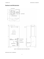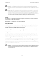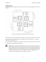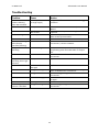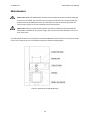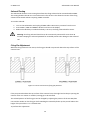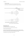
1
Salamander Flame Effect System User Manual Version 1 – February 2013 Le Maitre Ltd. Salamander User Manual Safety Information This information should be read and thoroughly understood before use of the Salamander. It is the responsibility of the user to be fully aware of all potential consequences and actions when using this machine. The manufacturer cannot be held responsible for events occurring due to use of this machine by unqualified or untrained personnel. Warning: All directions in the manual should be read thoroughly and completely understood before any attempt to use the machine. The machine should only be operated by or under the instruction of trained personnel. Any maintenance of the machine should only be carried out by the manufacturer or after the manufacturer’s strict approval. Should there be any doubt as to the safety of operation of the machine under any circumstances, the machine should be taken out of service immediately. The Salamander must not be used in confined spaces, under any conditions of rain, snow or precipitation of any fluids, or moving air which will cause the flame to divert from a vertical path. The Salamander should not be subjected to temperatures below 5°C or above 45°C, nor exposed to unsheltered conditions. Warning: Failure to observe correct operating procedures may lead to serious injury, damage by fire, or explosion. Warning: Before initial use and each subsequent use, the Salamander should be checked for functional suitability. Should any damage be observed or doubt about suitability of use occur, it should be immediately decommissioned and held for service. 1 Le Maitre Ltd. Salamander User Manual Operational Guidance The Salamander is only suitable for indoor use, or situations that meet the same environmental conditions. The machine must only be used vertically, secured in position, protected from unauthorised interference, impact forces and vibration. Any installation or repositioning should only be performed when the machine is cool, disconnected from the mains supply and all data communication. Changing canisters should only be performed when the machine is powered down, the HSI is cool, and no other sources of ignition are present. Safety distances must be given a priority when using the Salamander. This includes persons in the performance area, and surrounding flammable objects. Minimum safety distances are as follows: o o o Horizontal radius: 2 metres. Vertical safety height: 8 metres for a single unit. Vertical safety height: 12 metres if two or more units are coupled in a single location. Full risk assessments must be made before use, and all relevant emergency failure procedures must be immediately available, including qualified personnel, fire extinguishers and first aid. All operations should have undergone preliminary tests and rehearsal. Always ensure it is possible to shut the machine down immediately in case of emergency. Use of an Emergency Stop to interrupt mains supply is recommended. Use only Le Maitre Chameleon Flame Fuel or Le Maitre Salamander Flame Fuel. Use of alternate fuels might lead to unexpected behaviour. The Salamander is controlled by instruction from the DMX-512 protocol. The manufacturer cannot be held responsible for incorrect application or malfunction of data sent via DMX. 2 Le Maitre Ltd. Salamander User Manual Should DMX isolation or other devices be required for safe operation, this will be deemed the responsibility of the operator. Avoid live-wiring DMX to the Salamander, ie. do not plug in or unplug DMX cables while the controller is actively transmitting data. The Salamander is not designed for continual flame use. It is intended for short duration bursts, ie. maximum duration of 5 seconds. Should the Salamander fail to fire correctly, immediately shut down the machine and allow it to cool before investigating the problem. 3 Le Maitre Ltd. Salamander User Manual Contents Safety Information .................................................................................................................................. 1 Operational Guidance ......................................................................................................................... 2 Features and Dimensions........................................................................................................................ 5 Product Overview ................................................................................................................................... 6 Product Description ............................................................................................................................ 6 Features .............................................................................................................................................. 6 Specification ........................................................................................................................................ 7 Operation ................................................................................................................................................ 8 Getting Started.................................................................................................................................... 8 Control Panel....................................................................................................................................... 9 DMX Operation ................................................................................................................................... 9 Set-Up ............................................................................................................................................... 10 Coupling Units ................................................................................................................................... 11 Advanced Settings................................................................................................................................. 12 DMX Filter ......................................................................................................................................... 12 Tilt Switch .......................................................................................................................................... 12 Troubleshooting .................................................................................................................................... 13 Problem ............................................................................................................................................. 13 Cause ................................................................................................................................................. 13 Action ................................................................................................................................................ 13 Maintenance ......................................................................................................................................... 14 Firing Pin Adjustment........................................................................................................................ 15 O-Ring Replacement ......................................................................................................................... 16 HSI Testing......................................................................................................................................... 17 Contact Details ...................................................................................................................................... 18 UK ...................................................................................................................................................... 18 USA .................................................................................................................................................... 18 Warranty ............................................................................................................................................... 19 4 Le Maitre Ltd. Salamander User Manual Features and Dimensions Figure 1: Salamander Features and Dimensions All dimensions are in millimetres. 5 Le Maitre Ltd. Salamander User Manual Product Overview Product Description The Salamander is a versatile new real flame effect from Le Maitre Ltd. The small footprint and modular design allow the Salamander to produce stunning flame effects of over 6 metres in height with a purely canister based system. The unique firing mechanism eliminates the requirement for internal valves and accumulators, minimising the risk of flammable gas leaks, and a robust hot surface igniter ensures reliable flame ignition. The canister based design removes the requirement for bulky and expensive propane bottles and high pressure hosing, and allows for a choice of fuels making the Salamander ideal for any venue where propane is not permitted. Details of the full range of Le Maitre products are available online at: www.lemaitreltd.com and www.lemaitreusa.com Features 4m high flame effect from a single unit Over 6m high flame effect from 4 coupled units Canister based system Multiple colours and fuels available Total of 30 seconds continuous flames or up to 50 fireballs from a single canister No internal valves or accumulators; flammable fuels are only stored within the canisters themselves Small footprint Modular; designed to allow easy coupling of multiple units DMX operation Optional external display for remote monitoring Robust hot surface igniter Tilt safety switch Igniter current monitoring 6 Le Maitre Ltd. Salamander User Manual Specification Power Requirements (EU): (US): External Fusing (EU): (US): Fuel Capacity: Fuel Type: 230VAC, 50Hz, 250W 120VAC, 60Hz, 250W 3.15AT 6.3AT 1 x 500ml Canister Propane / Butane mix OR Ethanol / Methanol mix (colour specific) 30s continuous / up to 50 fireballs DMX512 – 2 Channels (Igniter, Fire) 433 (H) x 170 (W) x 204 (D) (including handle) 10kg Effect Duration: Control: Dimensions (mm): Weight: 7 Le Maitre Ltd. Salamander User Manual Operation Getting Started Remove the Salamander from all packaging and place on a flat, stable surface. Prior to use, the Salamander should be inspected for damage. If the unit is found to be damaged, it should be removed from service immediately, and referred to Le Maitre for servicing and repair. Install a canister of Le Maitre Chameleon or Salamander flame fuel by screwing the canister into the brass canister base. Be careful not to over-tighten the canister as this risks damage to the canister, the canister base, and the seals within the canister base. Unlike other flame effect systems, no gas should leave the canister as it is being installed. If escaping gas is detected, immediately remove the canister. The most probable cause is the tension of the spring supporting the firing pin. Refer to the Maintenance instructions for correct adjustment of this spring. Power is supplied to the Salamander via the blue Neutrik PowerCon socket. A suitable mains cable fitted with a blue PowerCon plug must be used to connect the Salamander to a mains supply. The white PowerCon socket is a mains through connector allowing multiple Salamander to be powered from a single mains supply. Please note: The blue Powercon must only ever be used as a mains input, and the white Powercon must only ever be used as a mains through / output. Please note: Electrically, the Salamander’s fuse and power switch are located after the mains through socket. This means the mains through socket will always be live while the Salamander is connected to a live mains supply, even if the unit is switched off, or the fuse has blown. 8 Le Maitre Ltd. Salamander User Manual Control Panel The Salamander is configured through an on board control panel featuring a 3 x 7-Segment LED display, 5 x indicator LEDs and 4 x multi-function buttons. Figure 2: Salamander Control Panel DMX Operation The Salamander can only be operated through DMX-512. Two channels are required – one channel activates the HSI, the second channel activates the firing solenoid. These two channels can be set independently. The HSI will be activated when the HSI channel is raised above 99%. The display will show the text H99. At this point, a timer will activate, preventing the unit from being fired until the HSI has had time to reach full temperature. While the timer is active, the 3 digit display will flash. When the display stops flashing, the unit is ready to fire. When the Fire channel is raised above 50%, a solenoid forces a plunger into the fuel canister, opening the canister valve and allowing the pressurised fluid to escape via the output nozzle located at the base of the flue. It is recommended that the fire channel is activated with the ‘flash’ buttons present on most DMX controllers. This allows for greater control over the effect produced. A brief activation of the channel (0.5 – 1s) will produce a short-duration fireball effect. A longer activation will produce a tall ‘tongue’ of flame. It is recommended that operators of the Salamander take some time to familiarise themselves with the effects produced in order to achieve the best results. 9 Le Maitre Ltd. Salamander User Manual Warning: The firing solenoid should never be continuously activated for more than 30 seconds. Keeping the solenoid powered for extended periods risks damage to the solenoid coil. Please note: After the Salamander has been fired, there can occasionally be seen a small flickering flame within the flue. This is produced by residual fuel in the nozzle vaporising after the Fire channel has been released. This is expected in normal operation, however, if the effect is not desirable, it can be minimised by gently warming the fuel canisters prior to use. This increases the volatility of the fuel, allowing it to vaporise more rapidly. Set-Up The Salamander is programmed for operation through the control panel (see above). This must be carried out with all DMX cables unplugged. When powered up, doF will flash. This is short for DMX OFF. Setting DMX Channels: Press the SELECT button. The HSI indicator LED will light up, and the currently selected HSI channel will be displayed. Use the UP / DOWN buttons to cycle through DMX channels. When the desired channel is selected, press STORE / VIEW to save the setting. Press SELECT again, and the FLAME indicator LED will light up. This is the Fire channel. Select the desired channel and save it as above. Pressing SELECT again will return to the DMX status display. Setting HSI Delay: Press STORE / VIEW and UP simultaneously. dEL will scroll across the display, followed by a value. This value corresponds to the timer delay after the HSI is activated before the Salamander can be fired. The default setting is 101. This corresponds to a delay of approximately 10s. In some adverse conditions it might be desirable to increase this delay. Care should be taken when adjusting the HSI Delay. If it is set too short, the HSI might not have time to reach full temperature when the Salamander is fired. This can result in the fluid failing to ignite. In addition, if the HSI Delay is reduced to 10 or below, the HSI will not activate. This allows the firing system to be tested without the HSI active. Warning: The canister must be removed before reducing the HSI delay. While the HSI delay is set to 6, the firing solenoid will activate. This will cause gas to be released if a canister is installed at the time. 10 Le Maitre Ltd. Salamander User Manual Coupling Units The Salamander has been designed to allow up to four units to be coupled together with a minimal footprint. Figure 3: Positioning of 4 coupled Salamanders (top-down view) When coupled in this manner, the effect has a footprint of less than 350 x 350mm, and can be used to give the impression of multiple different coloured flames from a single source, or to produce a single flame of much greater size. Daisy-chaining Mains and DMX connectors allows for the entire effect to be powered and controlled by a single mains supply and DMX line respectively. Please note: The US (120VAC) model will draw a peak current of about 7 Amps when the ignitor is activated. This inrush current will last for less than a second and settle rapidly to a steady-state current of about 1.5 Amps. However, this means four coupled units have the potential to draw an inrush current of 28 Amps. If there is any doubt that the mains supply being used can supply this peak current, it might be necessary to stagger the ignitor activation when multiple units are sharing a single mains supply. 11 Le Maitre Ltd. Salamander User Manual Advanced Settings DMX Filter In order to minimise the possibility of incorrect triggering of the Salamander through DMX, the software contains a DMX data filter. This will cause a small delay in the unit’s response to DMX commands (approximately 75ms.) In practical terms, this delay should be too short to have any effect on functionality, however it is possible to disable the DMX filter if this is desired. Warning: If the Salamander is operated with the DMX filter disabled, the manufacturer will not be held responsible for any unexpected behaviour under DMX control. To disable the DMX filter: 1. 2. 3. 4. With all DMX cables unplugged, press SELECT until doF is displayed. Press STORE / VIEW and UP at the same time. While dEL is still scrolling on the display, press DOWN. FILtEr will scroll across the display, followed by the setting. F – 1 indicates the filter is switched on. 5. Press UP and DOWN to toggle between filter on (F – 1) and filter off (F – 0). Tilt Switch The Salamander contains a safety tilt switch that will disable the unit if it is tipped beyond 40 degrees from vertical. This will prevent the unit from operating should it be knocked over. It is possible to disable this tilt-switch if desired. Warning: The Salamander is only designed to be used in a vertical position. If the unit is to be used in any other position, it is the sole responsibility of the user to ensure safe operation. To disable the tilt switch: 1. 2. 3. 4. 5. With all DMX cables unplugged, press SELECT until doF is displayed. Press STORE / VIEW and UP at the same time. While dEL is still scrolling on the display, press DOWN. While FILtEr is still scrolling on the display, press UP. tILt loc will scroll across the display, followed by the setting. L – 1 indicates the tilt switch is enabled. 6. Press UP and DOWN to toggle between tilt switch enabled (L – 1) and disabled (L – 0). 12 Le Maitre Ltd. Salamander User Manual Troubleshooting Problem Cause Action Fuse or circuit breakers blowing when HSI activated Too many Salamanders on single supply Assign HSIs different DMX channels and stagger activation Faulty HSI Refer to Maintenance instructions / contact Le Maitre Return to correct position. HSI might need to be replaced. Set HSI Delay to above 10 (101 recommended.) Refer to Set-Up Instructions. Set to correct DMX channel. Refer to Set-Up Re-connect HSI. Refer to Maintenance instructions / contact Le Maitre. HSI not heating HSI stuck in heating delay (display constantly flashing) Firing solenoid not activating HSI element in contact with chassis HSI Delay set below 10 Incorrect DMX channel HSI disconnected HSI still heating Wait until HSI is fully heated. The display will stop flashing when the Salamander is ready to fire. Set to correct DMX channel. Refer to Set-Up instructions. Replace canister. Incorrect DMX channel Firing solenoid activating, but no gas released Empty canister Canister nozzle damaged Firing pin sticking Replace canister. Firing pin too low. No response from unit Tilt lock-out engaged Gas leaking when canister is installed DMX signal not received Firing pin too high. 13 Remove firing pin and clean or replace o-ring. Refer to Maintenance instructions. Increase firing pin height. Refer to Maintenance instructions. Position on a level surface and turn unit off and on again. Check DMX controller and test cables. Reduce firing pin height. Refer to Maintenance instructions. Le Maitre Ltd. Salamander User Manual Maintenance Please note: While the Salamander contains several components that have been designed to be user-serviceable, the maintenance procedures described in this section should only be performed by qualified personnel. The manufacturer cannot be held responsible for events occurring due to incorrect maintenance of this machine. Please note: All the procedures described in this section should be performed with the Salamander isolated from any power supply, after the unit has been allowed to cool for at least 10 minutes. The Salamander features a service panel secured by 4xM4 bolts. Removal of this service panel allows access to the majority of user-serviceable components within the Salamander: Figure 4: Salamander Firing Mechanism 14 Le Maitre Ltd. Salamander User Manual Solenoid Testing The Salamander features a test setting that allows the firing solenoid to be activated without DMX. This setting disables the HSI so it cannot be used to fire the unit. This allows the action of the firing solenoid to be tested without requiring a DMX controller. To test the solenoid: 1. Turn on the Salamander and unplug all DMX cables. Remove any canisters from the unit. 2. Press STORE / VIEW and DOWN. dEL will scroll across the display. 3. Reduce the HSI delay to 6. While the delay is set to 6, the firing solenoid will be active. Warning: The firing solenoid should never be continuously activated for more than 30 seconds. Keeping the solenoid powered for extended periods risks damage to the solenoid coil. Firing Pin Adjustment While the firing solenoid is not active, the firing pin should not protrude above the top surface of the canister base: Figure 5: Correct and Incorrect firing pin positions If the pin protrudes above the top surface of the canister base, this might lead to the pin opening the canister valve as a canister is installed, causing gas to be released. The relaxed position of the firing pin can be changed by adjusting the position of the two M5 plain nuts and the washer on the firing pin shaft. Winding this assembly further up the pin will reduce the height of the pin while it is in a relaxed state. To perform this adjustment: 15 Le Maitre Ltd. Salamander User Manual 1. Depress the spring. 2. Using a 7mm spanner, wind the nuts up the firing pin shaft one at a time. 3. When the pin is in the desired position, tighten both nuts against the washer. Figure 6: Firing pin assembly and adjustment O-Ring Replacement The Salamander contains two user-replaceable O-rings. One is located at the base of the thread in the brass canister base. The other is located on the firing pin. The canister base O-ring should be inspected every time the canister is changed. If the rubber appears worn, frayed or split, the O-ring should immediately be replaced. It might be necessary to cut the O-ring out of the canister base using a small blade such as a scalpel. The replacement O-ring can simply be pressed into place. 16 Le Maitre Ltd. Salamander User Manual It is recommended that the firing pin O-ring is periodically examined for damage. Checking the Oring every 6-12 canisters is usually appropriate, however this will vary based on the precise operating conditions of the unit. In addition, if the Salamander fails to fire correctly, or the response when firing is delayed or ‘sticky’, the firing pin O-ring must be cleaned or replaced. To access the firing pin O-ring: 1. 2. 3. 4. Depress the spring. Pull the firing pin straight down towards the bottom of the canister base. When it meets the top of the thrust rod, gently twist it to one side. Pull the firing pin out past the side of the thrust rod. If the O-ring appears worn, frayed or split it must be replaced. The O-ring should be cut off the firing pin with a sharp blade such as a scalpel, taking care not to scratch the firing pin itself. A new O-ring should be eased into place from the top end of the pin. Do not push the O-ring over the thread on the firing pin. A small amount of lubricant, such as silicone grease, may be needed to get the O-ring into position. When the O-ring has been replaced, re-install the firing pin. Please note: Under no condition should the firing pin be pushed up out of the top if the canister base. This will force the firing pin O-ring across the canister base’s side opening, damaging the rubber and compromising the seal created. HSI Testing If the HSI is failing to heat up, or causing fuses to blow when it is activated, the HSI can be inspected to determine if it is faulty. To access the HSI: 1. Remove the Salamander Service Panel and Lid. 2. Undo the two M5 bolts securing the front two feet of the unit. These also secure the control panel. 3. Unplug the HSI from the chassis-mount relay on the control panel. Using a multimeter, the cold resistance of the HSI can be measured: EU (230V) Units: 86-120 Ohms. US (120V) Units: 9-16 Ohms. If the HSI resistance does not fall into this range, it has developed a fault. Contact the manufacturer for a replacement. 17 Le Maitre Ltd. Salamander User Manual Contact Details UK: Le Maitre Ltd 6 Forval Close Wandle Way Mitcham Surrey CR4 4NE Tel: +44 (0)20 8646 2222 Fax: +44 (0)20 8646 1955 Email: [email protected] USA: Tel: 1 (512) 451-4392 Fax: 1 (206) 350-3553 Email: [email protected] 18 Le Maitre Ltd. Salamander User Manual Warranty The Le Maitre Salamander is sold with a one year’s warranty, which includes parts and labour from the date of purchase. This warranty covers manufacturing defects, providing that the unit has been regularly serviced by an authorized agent and has only used genuine Le Maitre Canisters. Le Maitre Ltd considers all of its products to be safe for use in the application it was intended. Le Maitre Ltd takes no responsibility for misuse or incorrect use. Always refer to the equipment owner’s manual for proper use, and be aware of local legislation governing the products use. 19