1
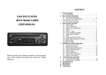
2442FX MKII
3242FX MKII
Mixing Console
2442FX MKII
ENGLISH
USER’S MANUAL
IMPORTANT SAFETY INSTRUCTIONS
shall be placed on the apparatus. The MAINS plug is used as the disconnect device, the disconnect device shall
remain readily operable.
Warning
can be easily accessible.
1. Read these instructions before operating this
apparatus.
CAUTION
2. Keep these instructions for future reference.
RISK OF ELECTRIC SHOCK
DO NOT OPEN
3. Heed all warnings to ensure safe operation.
4. Follow all instructions provided in this document.
5. Do not use this apparatus near water or in locations
where condensation may occur.
6. Clean only with dry cloth. Do not use aerosol or liquid
cleaners. Unplug this apparatus before cleaning.
7. Do not block any of the ventilation openings. Install
in accordance with the manufacturer s instructions.
8. Do not install near any heat sources such as radiators,
heat registers, stoves, or other apparatus (including
CAUTION: TO REDUCE THE RISK OF ELECTRIC SHOCK,
DO NOT REMOVE COVER (OR BACK)
NO USER SERVICEABLE PARTS INSIDE
REFER SERVICING TO QUALIFIED PERSONNEL
The lightning flash with arrowhead symbol, within an
equilateral triangle, is intended to alert the user to the
presence of uninsulated dangerous voltage within the
product
magnitude to constitute a risk of electric shock to persons.
The exclamation point within an equilateral triangle is in-
9. Do not defeat the safety purpose of the polarized or
grounding-type plug. A polarized plug has two blades
with one wider than the other. A grounding type plug
has two blades and a third grounding prong. The wide
blade or the third prong is provided for your safety. If
an electrician for replacement of the obsolete outlet.
10. Protect the power cord from being walked on or
pinched particularly at plug, convenience receptacles,
and the point where they exit from the apparatus.
manufacturer.
12. Use only with a cart, stand, tripod, bracket, or
the apparatus. When a cart is used, use caution
when moving the cart/apparatus
combination to avoid injury from tipover.
13. Unplug this apparatus during lighting
storms or when unused for long
periods of time.
Servicing is required when the apparatus has been
damaged in any way, such as power-supply cord or
plug is damaged, liquid has been spilled or objects
have fallen into the apparatus, the apparatus has
been exposed to rain or moisture, does not operate
normally, or has been dropped.
tended to alert the user to the presence of important operating and maintenance (servicing) instructions in the literature
accompanying the appliance.
WARNING:
not expose this apparatus to rain or moisture.
CAUTION: Use of controls or adjustments or performance
hazardous radiation exposure.
2442FX MKII
3242FX MKII
USER’S MANUAL
CONTENTS
4
4
4
4
4
5
5
6
7
7
8
8
8
9
9
9
10
11
12
13
14
15
16
17
July, 2009
INTRODUCTION
FEATURES
GETTING STARTED
Quick Setup
Channel Setup
INPUTS AND OUTPUTS
Mono Input Channels
Stereo Input Channels
Subgroups
Mono / Subwoofer Channel
Talkback Section
Control Room & Phones
CD/Tape Ins & Outs
Auxiliary Section
Graphic Equalizer
Digital Effect Processor
Master Section
Rear Panel
TYPICAL CONNECTING LEADS
DIGITAL EFFECT TABLE
APPLICATION
SPECIFCATIONS
DIMENSIONS
BLOCK DIAGRAMS
WWW.THOMANN.DE
2442FX MKII / 3242FX MKII USER’S MANUAL
INTRODUCTION
GETTING STARTED
Congratulations on your purchase of the T-mix
2442FX MKII or 3242FX MKII mixers - stylish
24- and 32-input mixers with 16 and 24 balanced
mic/line channels and four stereo line channels,
combined to make versatile yet brawny mixer. A
brand new line of mixers, the MIX series broadens
T-mix’s already impressive product line. The MIX
mixers include popular features that go further
than most, such as the 100-program Digital Effect
Processor (with tap delay and tone generator
built- in) dr iven by an ex traordinar y 32 /40 - bit
DSP engine. Featuring full gain ranges, low
distortion and an incredibly wide dynamic range,
the MIX mixers are bound to make an impression.
Quick Setup
We know how eager you are to get started – wanting
to get the mixer out and hook it all up is probably
your number one priority right now – but before
you do, we strongly urge you to take a look through
this manual. Inside, you will find important facts
and figures on the set up, use and applications of
your brand new mixer. If you do happen to be one
of the many people who flatly refuse to read user
manuals, then we just urge you to at least glance
at the Instant Setup section. After glancing at or
reading through the manual (we applaud you if you
do read the entire manual), please store it in a place
that is easy for you to find, because chances are
there’s something you missed the first time around.
FEATURES
●
●
●
●
●
●
●
●
●
●
●
●
4
Audiophile quality preamp design
DFX, 32/40-bit digital multi-effect processor with
100 programs.
16 or 24 mic/line channels with inserts
3-band EQ with swept mid-range
75Hz low-cut filter on each mono channel
4 AUX send mixing bus
AUX 1 & 2 with pre/post switch
4 subgroups and additional mono output
with sweepable low pass filter for subwoofer
application
Clip indication and gain level set LEDs plus mute
switches for each channel
Balanced main mix outputs with XLR and 1/4”
TRS connectors, headphone/control room output
and stereo tape outputs
Solo-In-Place and Pre-Fader-Listen functions
plus full-featured talkback section
Standby switch mutes all channels during breaks
while background music is provided via CD/tape
inputs
1. Ensure all power is turned off on your mixer. To
totally ensure this, the AC cable should not be
connected to the unit.
2. All faders and level controls should be set at the
lowest levels to ensure no sound is inadvertently
sent through the outputs when the device
is switched on. All levels can be altered to
acceptable degrees after the device is turned on
using the channel setup instructions.
3. P l u g a n y n e c e s s a r y e q u i p m e n t i n t o t h e
device’s various outputs. This could include
amplifiers and speakers, monitors, signal
processors, and/or recording devices.
4. Plug the supplied power supply into the inlet on
the back of the MIX mixer and into an AC power
outlet of a suitable voltage.
5. Turn the power switch on and follow the channel
setup instructions to get the most out of your
equipment.
Channel Setup
1. To ensure the correct audio level of the input
channel is selected, each of the GAIN controls
of the Mixer should be turned counterclockwise
as far as they will go (which should be the -20
mark).
2. Set the level control of the channel you are
setting to the 0 dB mark.
3. Ensure the channel has a signal sent to it similar
to the signal that will be sent when in common
use. For example, if the channel is using a
microphone, then you should speak or sing at
the same level the performer normally would
during a performance; if a guitar is plugged
into the channel, then the guitar should also be
strummed as it normally would be (and so on).
This ensures levels are completely accurate and
avoids having to reset them later.
4. Push to Solo button of the channel you wish to
set. You should now be able to see the channel’s
signal in the level meter.
5. Engage the Solo / PFL button below the level
meter, allowing you to see the input channel’s
pre-fader signal.
6. Adjust the gain level of the selected channel so
that the level meter sits around the 0 dB mark.
7. This channel is now ready to be used; you can
stop making the audio signal.
8. You can repeat the same process for other
channels.
2442FX MKII / 3242FX MKII USER’S MANUAL
INPUTS AND OUTPUTS
4
Mono Input Channels
There are 16 and 24 mono channels on the 2442FX
MKII and 3242FX MKII, respectively. To follow you
will find details on how these channels work; how
to make a connection, how to adjust the various
controls, and how to ensure you get those most out
of your mixer.
1. Microphone Input
These jacks accept typical 3-pin XLR inputs for
balanced and unbalanced signals. They can be
used in conjunction with microphones – such
as professional condenser, dynamic or ribbon
microphones - with standard XLR male connectors,
and feature low noise preamplifiers, serving for
crystal clear sound replication.
NB. When these inputs are used with condenser microphones,
the Phantom Power should be activated. However, when Phantom
Power button is engaged, single ended (unbalanced) microphones
and instruments should not be used on the Mic inputs.
2. Line Input
This input accepts typical 1/4” TRS or TS inputs, for
balanced or unbalanced signals. There are various
numbers of these inputs depending which mixer
you are using. They can be used in conjunction with
various line level devices, such as keyboards, drum
machines, electric guitars, and a variety of other
electric instruments.
3. Insert Point
5
1
6
2
7
3
8
10
9
11
7. Mid Frequency Control
You can provide a peaking style of boost and cut to
the level of midrange frequency sounds at a range of
±15 dB with this control. The MIX mixers also provide
a sweep control, allowing you to select a center
frequency between 100 Hz and 8 kHz. Changing
middle frequencies of an audio feed can be rather
difficult when used in a professional audio mix, as
it is usually more desirable to cut middle frequency
sounds rather than boost them, soothing overly harsh
vocal and instrument sounds in the audio.
8. Low Frequency Control
This control is used to give a shelving boost or cut
of ±15 dB to low frequency (80 Hz) sounds. This will
adjust the amount of bass included in the audio of the
channel, and bring more warmth and punch to drums
and bass guitars.
9. AUX Controls
4. Gain Control
This controls the sensitivity of the input signal of the
Line and Microphone inputs of mono channels. The
gain should be adjusted to a level that allows the
maximum use of the audio, while still maintaining
the quality of the feed. This can be accomplished by
adjusting it to a level slightly below that which will
cause the peak indicator to light up.
These four AUX controls alters the signal level that
is being sent to the auxiliary 1 to 4 mixing buses,
the signal of which is suitable for connecting stage
monitors, allowing artists to listen to music that
is being played. AUX 1 and 2 feature a Pre/Post
button, which alternates the feed to the AUX mixing
bus between a post and pre-fader feed. AUX 3, on
the other hand, acts as an EFX send, the signal of
which can be used in conjunction with external signal
processors (which can be returned to the mixer
via the AUX return input), or simply as an Auxiliary
output. Both the AUX 3 and AUX 4 (EFX) controls are
post fader. AUX 3 feeds directly AUX 3 output, AUX 4
feeds the AUX 4 output as well as the built-in effects
processor through the FX SEND control.
5. Low Cut Filter
10. AUX Pre/Post Button
Located on all mono channels, this button will
activate a high-pass filter that reduces all frequencies
below 75 Hz at 18 dB per Octave, helping to remove
any unwanted ground noise or stage rumble. Stereo
channels does not feature this low cut filter.
This button allows users to switch the signal sent to
the AUX 1 and AUX 2 mixes from the corresponding
input channel between a pre fader and post fader
signal. Pushed in, the signal is post-fader; released,
it’s a pre-fader signal.
6. High Frequency Control
11. Pan Control
Located on all mono channels, the primary use for
these TRS phone jacks is for the addition of external
devices, such as dynamic processors or equalizers,
to the corresponding mono input channel. This will
require a Y cord that can send and receive signals of
the mixer to and from an external processor.
Use it to give a shelving boost or cut of ±15 dB to
high frequency (12 kHz) sounds. This will adjust the
amount of treble included in the audio of the channel,
adding strength and crispness to sounds such as
guitars, cymbals, and synthesizers.
This alternates the degree or level of the mono audio
signal that the left and right channels of the main mix
should receive.
5
2442FX MKII / 3242FX MKII USER’S MANUAL
12
13
14
15
16
17
12. Mute Button and Indicator
Pushing the Mute button in will cut off the main mix’s
feed of the corresponding channels signal. Muting
a channel will also affect the AUX sends. Muting an
input channel is accompanied by the lighting up of
the Mute LED.
Stereo Input Channels
Stereo channels differ slightly to the mono channels
in their connections and controls. To follow you will
find a run-down on the differences and what these
channels are actually good for.
18. Stereo Inputs
The MIX mixers each feature 4 stereo
input channels, the inputs of which
18
differ slightly to the mono channels.
The two 1/4” TRS inputs are for the
addition of various stereo line level
input devices, such as keyboards
or drum machines. If you wish to use a monaural
device on a stereo return input, simply plug the
device’s 1/4” phone jack into the left (mono) stereo
input and leave the right input bare. The signal will
be duplicated to the right due to the miracle of jack
normalizing.
21
13. Clip LED
This LED indicator will illuminate when the channel
hits high peaks, slightly before the signal is
dynamically clipped. It is best to adjust the channel’
s level control so as to ensure the Clip indicator
does not light up. This will ensure a greater dynamic
range of audio. This indicator also doubles as a Solo
indicator, when the Solo button is engaged.
19
20
22
14. Solo Button
The Solo button is pushed to allow the signal of the
corresponding channel to be sent to the Control
Room / Phones mix (pre or post fader, depending
on the properties selected by the Solo/PFL button
located below the level meter), for use with either
headphones or studio monitors. This button also
allows for easier isolation of individual channel
signals, enabling simpler setting of the input gain or
tracking of audio by sound engineers. When the Solo
button is not engaged, the LED indicator works as a
Clip Indicator, illuminating when the signal reaches
high peaks.
15. 1-2 and 3-4 Buttons
The stereo channels of the MIX mixers feature
equalizer almost identical to those on mono
channels; however instead of a Mid frequency control
and sweep control there are High-Mid and LowMid controls instead. They provide a peaking style
of boost and cut to middle frequencies, where the
frequencies are set at 3 kHz and 800 Hz for the Highand Low-Mids respectively.
These two buttons allow users to route the channel’
s signal to their respective subgroups. There are four
subgroups in total. If users wish to send the channel’
s signal to, say, sub 1 but not sub 2, simply use the
channel’s pan (turn it hard to the left) to accomplish
this.
20. AUX Controls
16. Main Button
21. Balance Control
Pushing this button in allows the channel’s signal to
be sent to the Main mix.
17. Channel Fader
This control will alter the signal level that is sent from
the corresponding channel to the corresponding
mixing buses.
6
19. 4-Band Equalizer
The AUX controls on stereo channels are the same
as on mono channels, however, since the AUX mixes
are always mono, any stereo signal will be mixed into
a mono signal before being sent to the corresponding
AUX mix.
This rotary control alternates the degree or level
of audio that the left and right side of the main mix
should receive. Adjusting the balance control will
attenuate the left or right audio signals of the channel
accordingly.
22. Mute and Routing Buttons
The Mute, Main, 1-2 and 3-4 buttons on stereo
channels do not differ in their operation to mono
channels at all. However, it is important to make sure
that when the 1-2 and/or 3-4 buttons are pushed that
the Balance control is set to the middle, as this will
ensure the stereo signal remains a stereo signal.
2442FX MKII / 3242FX MKII USER’S MANUAL
24
25
23
26
27. Group Outputs
These 1/4” phone jacks output the
final feed from the Group mixes
27
1, 2, 3 and 4, the level of which is
determined by the Group Faders.
They can be used to feed a variety
of recording and PA devices, including multi-track
recorders, amplifiers and speakers, etc.
Mono / Subwoofer Channel
23.
Stereo Channels 21/22 & 23/24 (2442FX MKII)
Stereo Channels 29/30 & 31/32 (3242FX MKII)
The final 2 stereo channels on both MIX mixers feature
slightly simplified controls. Here you will find two AUX sends
(permanently wired to be pre-fader, useful in monitoring),
a level control and Solo button. As there are no routing
switches, the signal is permanently sent to the Main mix (and
appropriate AUX mixes).
Subgroups
The Subgroups on the MIX mixers allow users to
create single mono or stereo mixes of multiple input
channels and control them with a single fader. It
is also common to use the Group outputs as tapeoutputs for connecting to multi-track recorders.
24. Solo Buttons
The solo button allows the Group signal to be sent
pre or post fader (depending on the SOLO/PFL
button settings) to the Control Room / Phones mix,
allowing users to be able to monitor the subgroup
signal. When activated, the Solo LED will light up to
indicate as such.
25. Left / Right Buttons
The Group Controls also feature individual left and
right buttons, which allow you to send the various
Group signals to the Main Left and Right. This can
be handy when wanting to combine the signals
from different signals and control their input levels
simultaneously, then send them to the Main L/R
signal (eg. when multiple inputs are used for, say,
drums, you can combine these inputs together to be
controlled much simpler by a single fader).
26. Faders
These four faders are the final level control for the
Group 1 to 4 audio feeds, sent to the corresponding
Group outputs on the rear of the MIX mixers to feed
external devices such as effect processors, and,
most commonly, multi-track recorders. The Group mix
can be fed a signal from the various mono and stereo
channels, as well as the EFX signal, depending on
your selections. When pushed all the way up, these
faders provide 10 dB of gain to the signal, and, when
set all the way down, effectively mute the signal.
The Mono output is used as an auxiliary output (the
signal of which is taken from the main mix), and can
be connected to an amplifier and speakers. The
included low pass filter enables the signal of the
mono output to be more appropriate for use with a
subwoofer speaker, to add a little extra bass to your
sound.
28. Low Pass Filter
The low pass filter is activated by
moving the small slide switch to the
ON position. The accompanying
control allows users to adjust the cutoff frequency of the filter. If users
wish to use the Mono channel for
monitoring or other similar purposes,
the low pass filter should not be
activated.
29. Mono Fader
This fader controls the level of the
mono signal that is sent to the mono
outputs.
28
29
30. Mono Output
The line-level signal sent from the Mono
output can be used to connect to an
amplifier or active speaker. It is also
possible to use this output for monitoring
purposes, with headphones or active monitors.
30
Talkback Section
Handy in studios or on stage, the talkback function
built into the MIX mixers allows engineers or
producers – anyone, really – to communicate with the
performers wherever they may be.
31. Talkback Level Control
This control adjusts the level of the
talkback signal that is sent to the AUX
1 and AUX 2 outs.
32. Talk to AUX Button
31
32
33
Holding this button down activates the MIX’s builtin talkback microphone, the signal of which is sent
to the AUX 1 and 2 outputs. Keep the button pushed
down until you finish speaking.
33. Talkback Mic
Point your mouth here when wishing to communicate
with the performer/musician.
7
2442FX MKII / 3242FX MKII USER’S MANUAL
Control Room & Phones
39. CD / Tape Ins & Outs
The Control Room and Phones mixes are useful
for monitoring of audio signals. It is important to
remember, particularly when using headphones,
that listening to excessively loud audio signals for
prolonged periods of time could adversely affect your
hearing.
34. Level Control
This rotary control will allow users to adjust the
audio level of the Control Room / Phones signal (as
received by input channels, and those chosen by the
Source Select buttons). If active monitors are used
with the Control Room / Phones output, then this
control acts as the monitor level control.
These stereo RCA connectors allow users
to send signals to and from the mixer,
allowing devices such as CD players
and tape recorders/players to be used
in conjunction with your setup. Signals
received by the CD/Tape inputs are
adjusted by the “to Main” control.
Auxiliary Section
The Auxiliary outputs are included on this mixer
as a way to enable users to have a secondary
signal for whatever purpose necessary, whether it
be for connecting to signal processors or to active
monitors.
40. AUX Send Controls
This set of buttons allows users to select which
signals they wish to send to the Control Room /
Phones output. There is a button each for the AUX
1/2, CD/Tape, 1-2, 3-4 and Main mixes. These
signals can be monitored simultaneously, if wished.
These three controls are for adjusting
the audio level that is sent to the
corresponding AUX outputs, the signal
of which is initially taken from each 40
channel’s individual AUX send controls.
Pushing the accompanying SOLO
button will send the AUX sends 2 & 3 to
the Control Room / Phones mix (pre or
post fader, depending on the Solo / PFL
button) and be accompanied by an illuminated LED.
36. Control Room / Phones Output
41. AUX Send Outputs
34
35
35. Source Select
This 1/4” outputs feeds the signal altered by
the Control Room / Phones level control on
the face of the mixer to an external speaker or
headphones. This output has extensive use,
as it can be used to feed the signal from the 36
mixer to an active monitor, for the monitoring
of the audio signal from within a booth, among many
other possible uses.
CD/Tape Ins & Outs
The CD/Tape section allows for external consumerlevel devices, such as CD players or tape recorders,
to be incorporated into the mixer.
These four 1/4” phone jacks will output the
corresponding AUX send signals These can be
connected to external processing devices, and
subsequently returned to the AUX Return inputs.
They may also be used with active monitors, if
required.
42. AUX Return Inputs
These four 1/4” phone jacks make up 2 stereo AUX
return inputs. They can be used to return a signal to
the mixer that has been sent to an external processing
device and send the signal to the Main mix.
37. To Main Control
This control adjusts the level of the
signal received through the CD inputs
that is sent to the Main mix.
38. Standby Button
37
38
The Standby button is used to mute all input
channels of the MIX mixers. In this instance, the
CD/Tape input will still be in use, allow music to be
played between sets while ensuring no microphones
inadvertently pick up any audio. The main level
fader can remain in its normal position, ensuring you
don’t lose your mix.
8
39
42
41
2442FX MKII / 3242FX MKII USER’S MANUAL
44
45
43
Graphic Equalizer
The 9-band graphic equalizer will allow users to alter
the various frequencies of the audio in their Main or
AUX 1 mixes, for reducing feedback and adapting
audio to suit room acoustics.
43. Equalizer
This stereo 9-band equalizer allows users to cut and
boost the indicated frequencies by 12 dB. When the
feedback detection feature is activated, these sliders
will also illuminate to indicate program frequencies.
44. Main / AUX button
This button determines which signal will be
processed by the graphic equalizer. The AUX 1/2 and
Main signals are selectable.
45. EQ In Switch
Pushing this switch will turn the graphic equalizer on
and off.
Digital Effect Processor
The built-in digital effect processor encompasses a
32/40-bit digital processor and features 100 preset
programs, as well as various test-tones and tapdelay. For a completel list of effects, please observe
the Digital Effects Table.
46. Digital Effect Display
This 2-digital numeric display shows the program
number that is currently applied to your EFX audio
signal. When you rotate the Program control, you
can scroll through different program numbers;
however the display will revert back to the original
program if a new program is not selected within a
few seconds.
47. Sig and Clip Indicators
Located within the Digital Effect Display are Clip and
Sig LEDs. The Sig LED will light up when any signal
is received by the effect processor, and the Clip
LED will light up shortly before excessive signals
are dynamically clipped. If the Clip LED lights up too
often, it may be advisable to turn down one or all
EFX controls on input channels to ensure the signal
level is not too high.
48. Program Control
This control is used to scroll through the various
effects. Turning the control clockwise will allow users
to ascend into higher program numbers, and turning
it counter-clockwise will allow users to descend
into lower program numbers. Pushing this control
will apply the new effect. When a tap-delay effect
is selected, pressing this control will allow users to
select the tap-delay time.
49
48
47
46
By pushing the button several times, the effect
processor interprets the time between last two
pushes and remembers this as the delay time, until
the button is pushed again (this is kept, even after
the power is turned off). When the tap delay effect
is selected, a small LED will flash within the digital
effect display window at the selected intervals.
49. EFX Send Control
This rotary control will adjust the level of the output
signal at the AUX 4 send jack, as well as determine
the amount of audio the built-in effects processor
will receive. When this control is set to it’s minimum
position, neither the AUX 4 send nor the effect
processor will receive a signal.
50. FX to AUX 1 Control
This control allows users to send the signal
processed by the effects processor to the AUX 1
send mix, allowing for monitoring of the signal.
51. FX to AUX 2 Control
This control allows users to send the signal
processed by the effects processor to the AUX 2
send mix, allowing for monitoring of the signal.
50
51
52
53
54
52. FX to Main Control
The FX to Main control will allow users to adjust
the EFX signal that is sent to the Main or Group 1/2
mixes, as determined by the Main/Group button.
53./54. Main / Group Buttons
These button on the left (Main L/R / Group) allows
users to send the signal processed by the effect
processor to either the Main or Group mixes. If this
button is set to Group, using the Group 1/2 / Group
3/4 button will determine which of the group mixes
the signal will be sent. If the Main L/R / Group button
is set to Main, the Group 1/2 / Group 3/4 button will
be rendered useless.
Footswitch Jack
The foot switch port is for the inclusion of a foot
switch (not enclosed), used for remote activation and
deactivation of the built-in Digital Effect processor.
9
2442FX MKII / 3242FX MKII USER’S MANUAL
Master Section
The master section of the mixer features all the
goodies: the level meter, main level fader, +48V
and power indicators, the solo/PFL button, and so
on and so forth. This is where a lot of the magic
happens, so take care not to miss anything.
61
60
55. +48V Indicator
This LED indicator will light up when Phantom
Power is activated. To turn the MIX’s Phantom
Power on or off, simply flick the switch on the rear of
the mixer.
56. Power Indicator
The Power Indicator will light up when the power of
the mixer is on.
57. Level Meter
The dual 12 segment level meter gives an accurate
indication of when audio levels of the Main L/
R signal reach certain levels. The 0 dB indicator
illuminates is approximately equal to an output
level of +4 dBu (balanced), and the CLIP indicator
illuminates about 1.5 dB before the signal is
dynamically clipped. It is advised that users set the
various level controls so that the signal level sits
steadily around the 0 dB mark, to make full use of
audio while still maintaining fantastic clarity.
58. Solo / PFL Switch
Located underneath the Level Meter, this button
alters the Solo signals received by the Control
Room / Phones mix between Post (solo) and Pre
(PFL) fader signals. Whether set to Solo or PFL,
one of the corresponding LED indicators will light up
to indicate the current setting. If adjusting a signal
with the Control Room / Phones level control, it is
advisable that this button is set to Solo, ensuring the
signal is independent of any channel faders.
59. Main Fader
The Left and Right main mix is controlled with this
fader – the final level control for the Main Left and
Right audio feeds, sent to the Main L and R outputs.
When pushed all the way up, the Main L/R fader
provides 10 dB of gain to the signal, and when set
all the way down, the signal is effectively muted.
55
56
57
58
10
59
60. Main Outputs
These outputs will output the final stereo line level
signal sent from the main mixing bus. The primary
purpose of the two XLR jacks is to send the main
output to external devices, which may include power
amplifiers (and in-turn, a pair of speakers), other
mixers, as well as a wide range of other possible
signal processors (equalizers, crossovers, etcetera).
The two 1/4” phone jacks are able to send the Main
output to external devices that may run in parallel
with the mixer. This may include additional power
amplifiers, mixers, PA systems, as well as a wide
range of other possible signal processors.
61. Main Insert Point
Like the Insert Points on input channels, the primary
use for these TRS phone jacks is for the addition
of external devices, such as dynamic processors
or equalizers, to the Main L and R mix. This will
require a Y cord that can send (pre-fader) and
receive signals to and from an external processor.
When the main insert is in use, it will affect the
signal sent to both the 1/4” and XLR main outputs.
2442FX MKII / 3242FX MKII USER’S MANUAL
64
63
62
Rear Panel
Cleaning and Care
When this switch is in the on position, it activates
+48V of phantom power for all microphone inputs,
allowing condenser microphones (well, the ones that
don’t use batteries) to be used on these channels.
Activating Phantom Power will be accompanied by
an illuminated LED above the left channel Level
Meter. Before turning Phantom Power on, turn all
level controls to a minimum to avoid the possibility
of a ghastly popping sound from the speakers.
NEVER submerse the device or its
components in water or other fluids! Do
not allow any liquids to penetrate the
housing. This would damage the device
or cause a short circuit.
Cleaning the housing: Remove the power plug from
the power socket beforehand.
Clean the housing surface with a slightly damp cloth
Never use petrol, solvents or detergents that can
damage the units surface!
NB. Phantom Power should be used in conjunction with balanced
microphones. When Phantom Power is engaged, single ended
(unbalanced) microphones and instruments should not be used
on the Mic inputs. Phantom Power will not cause damage to most
dynamic microphones, however if unsure, the microphone’s user
manual should be consulted.
Disposal
62. Phantom Power
63. Power Switch
You can use it to turn the mixer on and off. Ensure
you turn all level controls down before activating.
64. Power Connector
Used for the addition of a power cable and supply,
allowing power to be supplied to the mixer. Please
use the power cable that is included with this mixer
only. The Fuse holder, located above the AC Power
connector, is, of course, for the MIX mixer’s fuse.
If the fuse happens to blow, open the holder cover,
and replace the fuse with a suitable replacement (as
indicated on the fuse holder’s cover).
Do not dispose of the device at the
end of his operating life in your normal
domestic waste. This device is subject
to the European Guidelines 2002/96/
EC.
• Have the product disposed of by a professional
disposal company of by your communal disposal
facility.
• Observe the currently applicable regulations. In
case of doubt contact your disposal facility.
• Dispose of packaging materials in an
environmentally responsible manner.
11
2442FX MKII / 3242FX MKII USER’S MANUAL
TYPICAL CONNECTING LEADS
12
2442FX MKII / 3242FX MKII USER’S MANUAL
DIGITAL EFFECT TABLE
NO
PARAMETER SETTING
ROOM
PROGRAM NAME
REV-TIME
EARLY LEVEL
NO
PARAMETER SETTING
PAN
PROGRAM NAME
SPEED
TYPE
00
COMPACT ROOM 1
0.05
100
56
SLOW PAN
0.1
R-->L
01
COMPACT ROOM 2
0.4
0
57
SLOW PAN 1
0.1
R<-->L
02
SMALL ROOM 1
0.45
100
58
SLOW PAN 2
0.4
R-->L
03
SMALL ROOM 2
0.6
90
59
MID SHIFT
0.8
R<-->L
04
MID ROOM 1
0.9
100
60
MID SHIFT 1
1.2
L-->R
05
MID ROOM 2
1
50
61
MID SHIFT 2
1.8
L-->R
06
BIG ROOM 1
1.2
100
62
MID SHIFT 3
1.8
R-->L
63
FAST MOVE
07
TUNNEL
HALL
3.85
100
REV-TIME
EARLY LEVEL
TREMOLO
3.4
R<-->L
SPEED
MODE-TYPE
08
JAZZ CLUB
0.9
90
64
LAZY TREMOLO
0.8
TRG
09
SMALL HALL 1
1.5
72
65
VINTAGE TREMOLO
1.5
TRG
10
SMALL HALL 2
1.75
85
66
WARM TREMOLO
2.8
TRG
11
SPRING HALL
1.9
98
67
WARM TREMOLO 1
4.6
TRG
12
MID HALL 1
2.3
100
68
HOT TREMOLO
6.8
TRG
13
MID HALL 2
2.45
80
69
HOT TREMOLO 1
9.6
TRG
14
RECITAL HALL
2.7
96
70
CRAZY TREMOLO 1
15
TRG
15
BIG HALL 2
3.3
88
71
CRAZY TREMOLO 2
20
TRG
REV-TIME
HPF
REV
DELAY
PLATE
DELAY+REV
16
SMALL PLATE
0.9
0
72
DELAY+REV 1
1
1
17
TAIL PLATE
1.2
20
73
DELAY+REV 2
2
2
18
MID PLATE 1
1.3
0
74
DELAY+REV 3
3
3
19
MID PLATE 2
2.2
0
75
DELAY+REV 4
4
4
20
REVERSE PLATE
2.25
42
76
DELAY+REV 5
5
5
21
LONG PLATE 1
2.6
80
77
DELAY+REV 6
6
6
22
LONG PLATE 2
3
625
78
DELAY+REV 7
7
7
23
LONG PLATE 3
4.2
0
79
DELAY+REV 8
8
8
DELAY AVERG.
R-BEVEL
CHORUS+REV
REV
CHORUS
24
SHORT DELAY 1
0.07
60
80
CHORUS+REV 1
1
1
25
SHORT DELAY 2
0.14
60
81
CHORUS+REV 2
2
2
26
PING PONG DELAY
0.11
55
82
CHORUS+REV 3
3
3
27
MID DELAY 1
0.15
55
83
CHORUS+REV 4
4
4
DELAY (STEREO)
28
MID DELAY 2
0.3
60
84
CHORUS+REV 5
5
5
29
SHORT DELAY 1(MONO)
0.06
100
85
CHORUS+REV 6
6
6
30
MID DELAY 1 (MONO)
0.13
100
86
CHORUS+REV 7
7
7
31
LONG DELAY 1(MONO)
0.18
100
87
CHORUS+REV 8
8
8
CHORUS
FLANGER+REV
REV
FLANGER
LFO
DEPTH
32
SOFT CHORUS
0.2
56
88
FLANGER+REV 1
1
1
33
SOFT CHORUS 2
0.5
70
89
FLANGER+REV 2
2
2
34
SOFT CHORUS 3
0.8
75
90
FLANGER+REV 3
3
3
35
WARM CHORUS
1.8
85
91
FLANGER+REV 4
4
4
36
WARM CHORUS 1
3.2
80
92
FLANGER+REV 5
5
5
37
WARM CHORUS 2
5.2
45
93
FLANGER+REV 6
6
6
38
WARM CHORUS 3
7.8
52
94
FLANGER+REV 7
7
7
39
HEAVY CHORUS
9.6
48
95
FLANGER+REV 8
8
8
LFO
DEPTH
40
FLANGER
CLASSIC FLANGER 1
0.1
44
96
GATED-REV-1 9
41
CLASSIC FLANGER 2
0.3
63
97
GATED-REV-2 10
42
GENTLE FLANGER
0.6
45
98
GATED-REV-1 9
43
WARM FLANGER
1.6
60
99
GATED-REV-2 10
44
MODERN FLANGER 1
2
85
45
MODERN FLANGER 2
2.8
80
46
DEEP FALANGER 1
4.6
75
47
DEEP FALANGER 2
10
60
PHASER
GATED-REV
RELEASE
REV
0.02
TAIL PLATE
0.2
TAIL PLATE
0.02
REVERSE PLATE
0.5
REVERSE PLATE
TAP DELAY
FB LEVEL
RANGE
TAP DELAY
0
100mS - 2.7S
A1
TAP DELAY
10
100mS - 2.7S
A2
TAP DELAY
20
100mS - 2.7S
A0
LFO
DEPTH
A3
TAP DELAY
30
100mS - 2.7S
48
CLASSIC PHASER 1
0.1
3.6
A4
TAP DELAY
40
100mS - 2.7S
49
CLASSIC PHASER 2
0.4
2.6
A5
TAP DELAY
50
100mS - 2.7S
50
COOL PHASER
1.4
0.7
A6
TAP DELAY
60
100mS - 2.7S
51
WARM PHASER
3.2
0.3
A7
TAP DELAY
70
100mS - 2.7S
52
HEAVY PHASER 1
5
1.2
A8
TAP DELAY
80
100mS - 2.7S
53
HEAVY PHASER 2
6
2.8
TEST TONE
FREQUENCY
SHAPE
54
WILD PHASER 1
7.4
0.8
T0
LOW FREQUENCY
100Hz
SINEWAVE
55
WILD PHASER 2
9.6
4.8
T1
MID FREQUENCY
1kHz
SINEWAVE
T2
HIGH FREQUENCY
10kHz
SINEWAVE
PN
PINK NOISE
20Hz~20kHz
13
2442FX MKII / 3242FX MKII USER’S MANUAL
APPLICATIONS
SPEAKER
DRUM MACHINE
MIC
BASS GUITAR
EQUALIZER
MIC
AMPLIFIER
Guitar
KEYBOARD
2442FX MKII
COMPRESSOR COMPRESSOR
MULTITRACK RECORDER
HEADPHONE
SPEAKERS
EQUALIZER
EXTERNAL EFFECT
PROCESSOR
AMPLIFIER
2442FX MKII
AMPLIFIER
KEYBOARD
SUBWOOFER
14
2442FX MKII / 3242FX MKII USER’S MANUAL
SPECIFICATIONS
MIX2442FX
2442FX
MKII
MIX2442FX
3242FX
MKII
24
16
4
4
2
32
24
4
4
2
2, (2*XLR, 2*1/4" TRS)
2, RCA
1, (1/4" TRS)
1, (1/4" TRS)
4 ( 4*1/4"TRS)
2, (2*XLR, 2*1/4" TRS)
2, RCA
1, (1/4" TRS)
1, (1/4" TRS)
4 ( 4*1/4"TRS)
1
1
60mm fader
4 (Pre/Post switch on Aux 1/2)
1
1
1
60mm fader
4 (Pre/Post switch on Aux 1/2)
1
1 (Rotary control with route switch)
60mm fader with sweptable LPF
60mm fader
1 (Rotary control with route
60mm fader with sweptable
60mm fader
2
12
48VDC
2
12
48VDC
20Hz ~ 40KHz
10Hz ~ 200KHz
Crosstalk (1KHz @ 0dBu, 20Hz to 20KHz
bandwidth, channel in to main L/R outputs)
0/-1dB
0/-3dB
0/-1dB
0/-3dB
Channel fader down, other channels at unity
<-90dB
<-90dB
Model
Inputs
Total Channels
Balanced Mono Mic / Line Channel
Balanced Stereo Line Channel
Aux Return
2T Input
Outputs
Main L/R Stereo
Rec Out
CTRL RM/PHONES
Mono (Sub) Out
Group Out
Channel Strips
Efx Send
Pan/Balance Control
Volume Controls
Aux Send
Inserts
Master Section
Phones Level Control
Mono (Sub) Out
Main L/R Level Control
Metering
Number of Channels
Segments
Phantom Power Supply
Frequency Response (Mic input to any
Noise (20Hz~20KHz; measured at main output,
Channels 1-4 unit gain; EQ flat; all channels on
main mix; channels 1/3 as far left as possible,
channels 2/4 as far right as possible.
Master @ unity, channel fader down
Master @ unity, channel fader @ unity
S/N ratio, ref to +4
Microphone Preamp E.I.N. (150 ohms
terminated, max gain)
THD (Any output, 1KHz @ +14dBu, 20Hz to
20KHz, channel inputs)
Maximum Level
Mic Preamp Input
All Other Input
CTRL RM/PHONES
Balanced Output
Impedance
Mic Preamp Input
Mono Line inout
Stereo Line Input
AUX RTN
RCA 2T Input
All Other Output (except REC Out, Phones Out)
CD/TAPE out
Phones Out
Equalization
Low EQ
Mid EQ
Hi EQ
Low Cut Filter
32/40-bit Digital Effect Processor
Power Requirement
Weight
Dimensions (WxHxD)
-96dB
-96dB
-84dB
-105dB
<-123dBu
-84dB
-105dB
<-123dBu
<0.014%
<0.014%
+12dBu
+22dBu
+17dBu/150ohms
+20dBu
+12dBu
+22dBu
+17dBu/150ohms
+20dBu
2.5k ohms
2.5k ohms
21k ohms
21k ohms
>10k ohms
>10k ohms
>10k ohms
>10k ohms
>10k ohms
>10k ohms
120 ohms
120 ohms
1.6k ohms
1.6k ohms
100 ohms
100 ohms
3-band +/-15dB
3-band +/-15dB
80 Hz
80 Hz
Sweptable 100Hz~8k Hz
Sweptable 100Hz~8k Hz
12k Hz
12k Hz
75Hz (-18 dB/oct)
75Hz (-18 dB/oct)
100 effects with tap delay control 100 effects with tap delay control
t l
100-240V~, 50-60Hz, 50W
100-240V~, 50-60Hz,
50W
appox. 8.5Kg
100X682X410mm
appox. 11.5Kg
100X896X410mm
15
2442FX MKII / 3242FX MKII USER’S MANUAL
DIMENSIONS
2442FX MKII
682.60/26.87
107.98/4.25
424.00/16.69
104.00/4.09
3242FX MKII
424.00/16.69
893.58/35.18
* All measurements are shown in mm/inches.
16
107.98/4.25
104.00/4.09
2442FX MKII / 3242FX MKII USER’S MANUAL
BLOCK DIAGRAMS
2442FX MKII
17
2442FX MKII / 3242FX MKII USER’S MANUAL
3242FX MKII
18
WWW.THOMANN.DE
Contact:
Musikhaus Thomann
Treppendorf 30
96138 Burgebrach
Germany
www.thomann.de