1
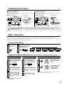
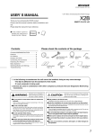
(PMC As of October, 2014 No.1)
USER’ S MANUAL
POWER MONITOR
0-100km/h TIME
WATER TEMP
VOLTAGE
Thank you for purchasing this PIVOT product.
Please read this manual carefully and keep it for future
reference.
WARNING
Improper use or disregard of
these warnings may result in
the injury or death of people.
●Do not work in areas where there is excessive
exhaust.
Due to vehicle exhaust emission poisoning or fire may
result in a damage to humans.
CAUTION
●This product is for DC12V cars;
Installation cannot be carried out on cars with other voltage batteries.
●Just after installation do not exert any strong force on the product.
When double-sided tape is used for an installation be warned that when hot the
tape temporarily losses adhesiveness.
●Do not crush the cable.
Please be careful that the cable does not get crushed by
the seat rail or car door steel plate, nor cut by any sharp
steel plate as this may cause a poor connection or an
electric short leading to fire or other danger.
●Do not operate while driving.
Operating or checking the display during driving may cause
an accident; please use with the utmost consideration for
safety.
●Please securely fasten the product and be sure
to store bundle away all wires with tape, etc...
It is very dangerous to pull tangled wires by force or allow
tangled wires to interfere with driving.
Improper use or disregard of these warnings
may c ause injur y to per sons, d amag e the
product and other things.
●Do Not Use Chemical Cleansers.
If the unit gets dirty please wipe with a soft cloth to remove any dirt. Do not use
chemical cleansers such as thinner, benzene, or alcohol.
●Do not install the product in any place subject to high temperature or any place where water may be splashed.
●Make sure to replace all screws and parts to their original place.
●Do not install the product in a place where it will cause distraction.
●Do not, in any manner, process, take apart, or make changes to
this product.
1. The display will not be proper if the ECU being used is not the standard one or if a sub-computer is being used, even in
compatible car models.
2. Cannot be used in combination with other company’ s products that use Diagnostic Monitoring Connectors.
3. For details about using in combination with other PIVOT products that use Diagnostic Monitoring Connectors please
see our Web Site at http://pivotjp.com/obd- e/.
Please check the contents of the package
Monitor
[50×34×14(D)mm]
Unit
[51×35×20(D)mm]
OBD Cable
with fuse 3A
IGN Cable
with fuse 3A
Male Connector
with Cover
Female Connector
with Cover
×2
Double-sided
Tape
×2
Zip Tie
×2
Cut
Connector
User’ s
Manual
(This Book)
Features
Easy-to-Install, Automatically Measure 0-100km/h Time for Power check.
■ 0-100km/h Time
Automatically Measure 0-100km/h Time to set speed from stop.
Measurement speed=40/60/100(km/h)
*When measuring on public roads, observe the speed limit.
*When measuring on public roads, observe the speed limit.
■ Multi-Data Display
Switch between 0-100km/h Time, Water Temperature and
Voltage in the same unit.
■ Easy Installation
Simply connect to the diagnostic monitor connector.
■ Thin Compact Monitor
14mm Flat-Design allows for Unobtrusive Installation.
■ Peak Hold
The highest value of Water Temperature and the lowest value
of Voltage will be displayed.
Part Names
1 Display
Display 0-100km/h Time,
Water Temperature and
Voltage.
POWER MONITOR
2 PEAK/TIME Switch
Use to display and reset
the peak value and measure the time.
3 MODE Switch
Use to change display
modes.
0-100km/h
WATER °C
VOLTAGE
PEAK
TIME
2
MODE
1
3
1
Connecting the Wires
① Insert the OBD Connector to the Diagnostic Monitoring Connector.
② Insert the 5-pin Connector from the Monitor and 7-pin Connector from the OBD Cable to the Unit.
Diagnostic
Monitoring
Connector
②
①
②
Unit
5-pin
Connector
Monitor
7-pin
Connector
In case of installing in Euro car (BMW· MINI ·AUDI)
●Change the power source from normal power of the Diagnostic Monitoring Connector to IGN.
IGN is “12V simultaneously with key ON” and “0V simultaneously with key OFF”
①Cut the Red cable of OBD Cable and insulated the
cut off cable of OBD Connector side.
②Connect to IGN using the Cut Connector, Male and Female
Connectors and IGN Cable as in the diagram below.
OBD Cable
OBD Cable
OBD
Connector
*Must be Insulated
IGN Cable
Red
Red
*Must be Insulated
Yellow
IGN
=Cut Connector
=Male Connector
【Data】Placement Diagram for Diagnostic Monitoring Connector
⑧
⑥
⑨
TOYOTA
④
③
⑤
①②③④⑦
OBD
Connector
⑦⑩
②
①
MAZDA
②④⑩
NISSAN ① ② ③ ④ ⑤ ⑦
SUBARU
②③
HONDA ② ④ ⑤ ⑥ ⑧ ⑨
SUZUKI
②④
MITSUBISHI ② ③ ④ ⑤
DAIHATSU ② ③ ④ ⑤
①
②
③
④
⑤
⑥
⑦
⑧
⑨
⑩
(Normal power, not ACC)
=Female Connector
【Reference 1】Notes about using the OBD Connector
By the accelerator pedal
At the right foot of the driver seat (with lid)
At foot of driver seat in the center (with lid)
At the left foot of the driver seat (with lid)
At the right side of the center console
At the right foot of the passenger seat
Behind the panel by the steering (with lid)
At the left foot of the passenger seat
At the left side of the center console
Panel to right of steering wheel
(upper part of small storage box)
CAUTION
Make sure to grip the distended portions when pulling it out
or inserting it.
If you unable to get a grip
on the distended portions.
Do not pull on the wires
when trying to remove the
connector; the wires may
become disconnected.
In such case, pull out
the connector by
pulling on
t h e e n d of
the zip tie.
If you unable to get a grip
on the distended
portions.
【Reference 2】How to use the Male Connectors
1
Male sleeve
2
Wire
Remove about 10 mm of the
cable casing.
Pull the cable through the
male sleeve.
6
10 mm
Affix the male sleeve
to the places as
mentioned above.
3
4
Turn back the tip of
the wires.
Connect the male connector
to the end of the cable.
Male Connector
N OT E: Af te r c o n n e c t i n g t h e m a l e a n d
female connectors, make sure to firmly twist
the male sleeve inside the female sleeve.
5
Crimp these places
Crimp down with crimpers to make
sure that the inner wires are firmly
connected to the inner part of the
connector and that the cable section
is connected to the outer part of the
connector.
【Reference 3】How to use the Cut Connectors
1
10 mm
Peel off of the vinyl
cover at connection.
2
2
10 mm
Peel of f of the vinyl
c ove r at t h e e n d of
the product’ s wire.
3
4
Wrap around both
wire coils.
5
Close tightly with
cut connector.
Insulate with vinyl
tape.
When crimping, please
use crimpers or use
pliers to bend and then
solder together.
Installing the Product
● Installing the Monitor
● Installing the Unit
Affix with double-sided tape to a position which is easy to see and
which allows for easy operation.
As shown in the diagram below, fasten the unit into positions not
usually affected by water.
(How to Install)
(Example of Installation)
(How to Install)
(Example of Installation)
Clean to remove
oil and dust.
Unit
Double-sided
tape
(Included)
Double-sided
tape
(Included)
Clean to
remove
oil and dust.
Controller
Please be sure to bundle away
all wires with tape, etc…
While in use if wires become free they may interfere with driving and cause accidents.
Also, wires which are smashed or crushed may result in a short and can be extremely dangerous.
Basic Operation
Due to analyzation time for the CAN data transmission it may take up to 5 seconds from engine start before the display lights up.
This product is interlocked with the ECU (engine computer) power. Depending on the model of car, the illumination may remain on for up to 3
minutes even after the engine has been turned off; this is normal.
Change Display Modes
1
Key Switch ON
(Engine start)
2
The Mode will change
with each pressing of
the MODE switch.
Water Temp
START
Voltage
0-40km/h Time
0-60km/h Time
0-100km/h Time
Display and reset the Peak Value (Water temp: ascending side / Voltage: descending side)
Peak reading display
1
Press the PEAK switch
while displaying Water
temp or Voltage
Peak reading display
1
Press the PEAK switch
for 3 seconds while
displaying Peak Value
Measuring the lowest voltage by voltmeter
1
ON
ENGINE
or
START
STOP
Turn the key switch
ON and display the
meter
Without braking,
press down twice
2
2
Peak reading display
2
The Peak Value blinking.
3
Real-time display
Reset the Peak Value
Blinking display changes to
lighting.
3
Real-time display
START
or
ENGINE
START
STOP
With braking,
press down once
Start the engine and
check the lowest
voltage with Peak
reading display
●Recommend to charge or replace the battery if it's lower
about 1V or more than when new.
Back to real-time display
after 3 seconds releasing
the switch.
※Each peak value can be reset
by the key OFF.
3
Measuring the Time (0-40/60/100km/h Time)
1
2
4
Stop the car on the place
you want to star t mea suring the time
Press the MODE switch
to chose mode to measure
*When measuring on public roads, observe the speed limit.
Automatically M easure
when the car start driving
(Beep will sound 0.5 second)
Stop
5
e.g.
0-100km/h Time
Start driving
Display the measured time
when reach the set speed
(Beep will sound 1 second)
3
Press the TIME switch
to ready to measure
Ready
(e.g. 8 seconds 25)
Measure again
Change Mode
Press the TIME switch
and see 4
Press the MODE switch
to change mode
●If operate the switch after the measurement, the measurement data will be erased.
●The maximum time of measuring is 59 seconds 9.
●If the measuring time will be more than 59 seconds 9, the display will return to step 2 .
●If you stop the car while measuring, the display will return to step 2 .
Reading Display and Display Range
Water Temp
Display Range: -35 to 150 °C
1 °C unit
-35 〜 -1°C
0 〜 99°C
100 〜 150°C
The first place
on the left shows
“ ” (minus).
The third place
from the left shows
“ ” (celsius).
N u m er i c a l
Value Only.
-
c
Voltage
Display Range: 8 to 18 V
0.1 V unit
The second place from the left shows
the “ ” (decimal point).
.
*Some car models cannot display
Voltage. Check the “Fitting List” .
Measuring
the Time
Display Range:
0 to 59 seconds 9
0 〜 9 seconds 99
10 〜 59 seconds 9
The first place on the
left shows the “ ”
(decimal point).
Measuring 0 second
01 unit.
The second place from
the left shows the “ ”
(decimal point).
Measuring 0 second 1
unit.
.
.
Troubleshooting
Trouble
Possible Causes
Possible Solutions
Does not become ready in measuring the
time.
The car is not stopped completely.
Stopped the car completely and press the
TIME switch.
The measured values are different from the
standard meter.
Standard Meter appears slightly higher
(about 10km/h).
The display of this product is correct.
Upon starting up, the unit will start in the
newly changed mode.
The car’ s engine is turned off within 3
seconds after changing modes.
Stop the car’ s engine after more than 3
seconds after changing modes.
Does not work with Engine start.
Poor connection of 5-pin Connector, 7-pin
Connector or OBD connector.
Pl e a s e r e c o n f i r m w h e t h e r w i r i n g a n d
connections are correct or not.
The unit has been installed into an incompatible car model.
Please check the “Fitting List” .
※Our products have already been recognized as our Industrial Property or are in the process of receiving Industrial Property status.
※We plan in the near future to take all possible legal measures to protect against unfair competition from look-alike products using similar designs,
regulating characteristics, circuitry and circuitry layout.
※We strictly prohibit the unlicensed use of the PIVOT trademark and the unauthorized use of PIVOT User’ s Manual.
4
PIVOT CORPORATION 87-3, Shimookada Okada, Matsumoto-shi, Nagano, 390-0313 JAPAN
http://pivotjp.com/