1
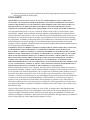
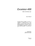
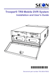
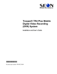
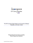
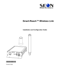
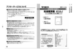
Scout™ Basic Mobile VCR
System
Installation and User’s Guide
Manual Type
*700-0016*
Document part number 700-0016 R007
Seon Design® Inc.
Seon Design Inc. is a specialist in the design and manufacture of video surveillance systems for mobile applications. Seon has
been the preferred solutions provider for the pupil transportation industry since 1999. Today, we are proud that our success in
this area has made us the leading manufacturer of mobile video surveillance systems in North America.
Contact Information
Seon Design Inc.
Unit 111, 3B Burbidge Street
Coquitlam, BC
Canada V3K 7B2
Telephone
Toll Free Telephone
Fax
Toll Free Fax
Email
Web site
604.941.0880
1.877.630.7366
604.941.0870
1.866.664.3677
[email protected]
www.seon.com
Seon Design Inc. Trademarks
Seon Design Inc. holds the following trademarks:
Scout™ is a registered trademark of Seon Design Inc.
“Seon Design” is a registered trademark of Seon Design Inc.
The Seon logo (
) is a registered trademark of Seon Design Inc.
In this User Manual there are references to trademarks, registered trademarks, and product names not owned by Seon Design
Inc. that are the property of their respective owners. They are used in this User Manual for identification purposes only.
User Manual Revision
This is the February 2008 revision for this User Manual and is copyright, February 2008 of Seon Design Inc. All rights
reserved.
Exclusion of Liability
SEON DESIGN INC.:
(a) MAKES NO REPRESENTATION, WARRANTY, GUARANTEE OR COVENANT, EXPRESS OR IMPLIED, AS TO THE ACCURACY,
SUFFICIENCY OR SUITABILITY OF ANY TECHNICAL OR OTHER INFORMATION PROVIDED IN THIS USER MANUAL OR ANY OTHER
USER OR OTHER MANUAL OR OTHER DOCUMENTATION PROVIDED BY SEON DESIGN INC. WITH RESPECT TO THE PRODUCT(S)
DESCRIBED HEREIN, INCLUDING WITHOUT LIMITATION ANY DESCRIPTION OF GOODS OR SERVICES, SPECIFICATIONS, MODELS,
DRAWINGS, OR DIAGRAMS.
(b) DOES NOT ASSUME AND SHALL NOT BE SUBJECT TO AND DISCLAIMS ANY AND ALL RESPONSIBILITY AND/OR LIABILITY FOR
LOSSES, DAMAGES, COSTS OR EXPENSES ARISING OUT OF BREACH OF CONTRACT OR OF WARRANTY, TORT (INCLUDING
NEGLIGENCE AND STRICT LIABILITY) OR OTHERWISE, WHETHER SPECIAL, DIRECT, INDIRECT, CONSEQUENTIAL, INCIDENTAL,
SPECIAL OR CONTINGENT, WHICH MIGHT ARISE OUT OF THE USE OF SUCH INFORMATION. THE USE OF ANY SUCH INFORMATION
WILL BE ENTIRELY AT THE USER ’S RISK; AND
(c) EXPRESSLY DISCLOSES THAT IF THIS MANUAL IS WRITTEN IN ANY LANGUAGE OTHER THAN ENGLISH, THAT ALTHOUGH
SEON DESIGN INC. HAS USED REASONABLE CARE TO MAINTAIN THE ACCURACY OF THE TRANSLATION FROM THE ENGLISH
LANGUAGE, THE ACCURACY OF SUCH TRANSLATION IS NOT GUARANTEED OR WARRANTED BY SEON DESIGN INC. PLEASE REFER
TO THE ENGLISH LANGUAGE VERSION OF THIS USER MANUAL FOR APPROVED SEON CONTENT. THE ENGLISH LANGUAGE
VERSION IS AVAILABLE UPON REQUEST FROM THE SEON CUSTOMER SERVICE DEPARTMENT.
Please refer to the Seon Design Inc. Product Warranty applicable to the Product(s) described in this User Manual which
exclusively sets forth Seon Design Inc.’s entire liability arising from or in connection with such product(s) and their use and
the exclusive remedies available for purchasers and users thereof.
Document Part Number
This User Manual is valid for Seon Design Inc. Document Part Number 700-0016.
PRINTED IN CANADA
Who this Guide is For
This Installation and User’s Guide provides installation and operating information for the Scout™ Basic Mobile VCR
System (Scout Basic). The Guide is intended for anyone who needs to install and operate the Scout™ Basic Mobile
VCR System.
Conventions Used
CAUTION
Cautions identify conditions or practices that could result in damage to the unit or other
equipment.
Important: These notes describe things which are important for you to know, but are
not as serious as a Caution.
Related Documentation
SA Series Wedge Camera Setup Guide, document part number 700-0004
Accessories
A remote control is available for use with the Scout Basic VCR.
Finding Information Online
You can find more information about Seon Design Inc. as well as its products and services at www.seon.com.
Contents
Chapter 1
Introduction
1.1. Scout Basic System - - - - - - - - - - - - - - - - - - - - - - - - - - - - - - - - - - - - - - - - - - - - - - - - - - 1–2
1.2. Scout Basic Product Features - - - - - - - - - - - - - - - - - - - - - - - - - - - - - - - - - - - - - - - - - - - 1–2
1.2.1. Front Panel Features - - - - - - - - - - - - - - - - - - - - - - - - - - - - - - - - - - - - - - - - - - - - - 1–2
1.2.2. Back Panel Features - - - - - - - - - - - - - - - - - - - - - - - - - - - - - - - - - - - - - - - - - - - - - - 1–2
1.3. Lock Box - - - - - - - - - - - - - - - - - - - - - - - - - - - - - - - - - - - - - - - - - - - - - - - - - - - - - - - - - 1–3
1.4. Cables and Harnesses - - - - - - - - - - - - - - - - - - - - - - - - - - - - - - - - - - - - - - - - - - - - - - - - - 1–3
Chapter 2
Installation
2.1. Installing the Scout Basic VCR and Lock Box - - - - - - - - - - - - - - - - - - - - - - - - - - - - - - - - 2–2
2.2. Step 1: Installing the Lock Box - - - - - - - - - - - - - - - - - - - - - - - - - - - - - - - - - - - - - - - - - - 2–2
2.3. Step 2: Installing the VCR in the Lock Box - - - - - - - - - - - - - - - - - - - - - - - - - - - - - - - - - - 2–4
2.3.1. Connecting to the VCR Back Panel - - - - - - - - - - - - - - - - - - - - - - - - - - - - - - - - - - - 2–5
2.4. Step 3: Installing the Camera- - - - - - - - - - - - - - - - - - - - - - - - - - - - - - - - - - - - - - - - - - - - 2–6
2.4.1. Checking the Camera Cable Connections - - - - - - - - - - - - - - - - - - - - - - - - - - - - - - - 2–6
2.4.2. Connecting the Camera to the VCR Back Panel - - - - - - - - - - - - - - - - - - - - - - - - - - - 2–7
2.5. Step 4: Connecting the Power and Ignition Harness, Fuses, and Fuse Holders - - - - - - - - - - - 2–8
2.6. Step 5: Hardware Installation Final Checklist- - - - - - - - - - - - - - - - - - - - - - - - - - - - - - - - 2–10
2.7. EZN Decoy System - - - - - - - - - - - - - - - - - - - - - - - - - - - - - - - - - - - - - - - - - - - - - - - - - 2–10
Chapter 3
Configuring the VCR
3.1. Configuring the VCR - - - - - - - - - - - - - - - - - - - - - - - - - - - - - - - - - - - - - - - - - - - - - - - - - 3–2
3.2. Scout Basic VCR Main Menu - - - - - - - - - - - - - - - - - - - - - - - - - - - - - - - - - - - - - - - - - - - 3–3
3.2.1. Using the Remote Control - - - - - - - - - - - - - - - - - - - - - - - - - - - - - - - - - - - - - - - - - - 3–3
3.2.2. Using the Set Time/Date/Title Menu - - - - - - - - - - - - - - - - - - - - - - - - - - - - - - - - - - - 3–4
3.2.3. Using the Record Mode/Schedule Menu - - - - - - - - - - - - - - - - - - - - - - - - - - - - - - - - 3–6
3.2.4. Using the Load Factory Defaults Menu - - - - - - - - - - - - - - - - - - - - - - - - - - - - - - - - - 3–8
3.2.4.1. Software Version - - - - - - - - - - - - - - - - - - - - - - - - - - - - - - - - - - - - - - - - - - - - 3–8
Chapter 4
Operation and Maintenance
4.1. Operating the VCR - - - - - - - - - - - - - - - - - - - - - - - - - - - - - - - - - - - - - - - - - - - - - - - - - - 4–2
4.1.1. Using the Front Panel - - - - - - - - - - - - - - - - - - - - - - - - - - - - - - - - - - - - - - - - - - - - - 4–2
4.1.2. Recording Video - - - - - - - - - - - - - - - - - - - - - - - - - - - - - - - - - - - - - - - - - - - - - - - - 4–3
4.1.3. Stopping Video Recording - - - - - - - - - - - - - - - - - - - - - - - - - - - - - - - - - - - - - - - - - 4–3
4.1.4. Playing Back Video - - - - - - - - - - - - - - - - - - - - - - - - - - - - - - - - - - - - - - - - - - - - - - 4–4
4.2. Other Operating Features - - - - - - - - - - - - - - - - - - - - - - - - - - - - - - - - - - - - - - - - - - - - - - 4–4
4.2.1. Smart-Temp™ - - - - - - - - - - - - - - - - - - - - - - - - - - - - - - - - - - - - - - - - - - - - - - - - - 4–4
700-0016 R007
iii
Contents
4.2.2. Low Voltage Indicator - - - - - - - - - - - - - - - - - - - - - - - - - - - - - - - - - - - - - - - - - - - 4.2.3. Stereo Recording - - - - - - - - - - - - - - - - - - - - - - - - - - - - - - - - - - - - - - - - - - - - - - 4.3. Maintenance - - - - - - - - - - - - - - - - - - - - - - - - - - - - - - - - - - - - - - - - - - - - - - - - - - - - - 4.3.1. Cleaning the VCR Recording Heads - - - - - - - - - - - - - - - - - - - - - - - - - - - - - - - - - 4.3.2. Cleaning the Lock Box - - - - - - - - - - - - - - - - - - - - - - - - - - - - - - - - - - - - - - - - - - 4.3.3. Cleaning the Camera and Window - - - - - - - - - - - - - - - - - - - - - - - - - - - - - - - - - - 4.3.4. Maintaining Video Tape Quality - - - - - - - - - - - - - - - - - - - - - - - - - - - - - - - - - - - - 4.4. Returning Product For Service - - - - - - - - - - - - - - - - - - - - - - - - - - - - - - - - - - - - - - - - - -
Chapter 5
4–4
4–5
4–5
4–5
4–5
4–5
4–5
4–6
Troubleshooting
5.1. Troubleshooting the Scout Basic - - - - - - - - - - - - - - - - - - - - - - - - - - - - - - - - - - - - - - - - - 5–2
Appendix A
Specifications
A.1. Scout Basic VCR- - - - - - - - - - - - - - - - - - - - - - - - - - - - - - - - - - - - - - - - - - - - - - - - - - - A–1
A.2. VCR Configurable Features- - - - - - - - - - - - - - - - - - - - - - - - - - - - - - - - - - - - - - - - - - - - A–2
A.3. Lock Box - - - - - - - - - - - - - - - - - - - - - - - - - - - - - - - - - - - - - - - - - - - - - - - - - - - - - - - - A–2
SEON DESIGN® INC. PRODUCT WARRANTY
DISCLAIMER- - - - - - - - - - - - - - - - - - - - - - - - - - - - - - - - - - - - - - - - - - - - - - - - - - - - - - - -W–2
Provisions Applicable to American Customers - - - - - - - - - - - - - - - - - - - - - - - - - - - - - - - - - -W–3
Provisions Applicable to Canadian Customers - - - - - - - - - - - - - - - - - - - - - - - - - - - - - - - - - -W–3
iv
700-0016 R007
CHAPTER 1
Introduction
This chapter describes the product features and components of the Scout™
Basic Mobile VCR System (Scout Basic System).
Introduction
1.1. Scout Basic System
The Scout Basic System consists of the following components:
•
•
•
•
•
Scout Basic VCR
Lock box
Camera
Video tape
Cables and harnesses for power and ignition input
1.2. Scout Basic Product Features
The Scout Basic System has been designed using extremely reliable and easy-touse technology, including:
•
•
•
•
•
•
•
•
Hi-Fi audio for increased quality and vibration resistance
Eight hours of recording with T-160 tape
On-screen display of operational status (time, date, vehicle identification, and
system voltage)
Smart-Start™ to prevent potential damage to the VCR from voltage spikes
and drops during vehicle start-up
Smart-Temp™ and built-in heater to prevent tape damage at low temperatures
Configurable software
• Repeat recording, user selectable ON or OFF
• Variable delay-on and delay-off recording, selectable up to 60 minutes
• Five daily timers to set the VCR recording time
Temporary power for tape removal without turning on the vehicle ignition
Front panel video output and audio output jacks for setup and playback
1.2.1. Front Panel Features
The Scout Basic VCR has important features on the front panel such as the
POWER, EJECT and REC buttons, REW, PLAY, FF and STOP buttons, VIDEO OUTPUT
and AUDIO OUTPUT jacks.
For more information, see “Using the Front Panel” on page 4–2.
1.2.2. Back Panel Features
The input connectors are located on the back panel where the cables and harnesses
connect to the VCR. For more information, see Figure 2-4 on page 2–5.
1–2
700-0016 R007
Introduction
1.3. Lock Box
The lock box secures the VCR into a location on the bus and provides the
following features:
•
•
•
•
A locking door which prevents unauthorized access to the VCR controls.
Authorized personnel can use the lock box key to remove the hinged locking
door when access to the VCR is necessary.
A sliding rail system that allows for easy VCR installation and exchange.
A slotted cable entry that allows connectors to be inserted into the lock box
after installation.
Mounting orientation accommodates a horizontal installation—flat on the
floor or under a seat. (For installing the VCR under a seat, use of the
Underseat Mounting Bracket Kit is recommended. Contact your Seon Design
sales representative for more information.)
1.4. Cables and Harnesses
The wiring connections to the Scout Basic System includes:
•
•
•
700-0016 R007
A 20 foot camera cable which comes with the camera, using a single
connector for ease of installation.
A high-reliability power input harness for easy wiring of power and ignition
trigger.
In-line fuses on the power and ignition lines for added protection.
1–3
1–4
CHAPTER 2
Installation
This chapter provides information and procedures for installing the Scout
Basic System.
Installation
2.1. Installing the Scout Basic VCR and Lock Box
The Scout Basic VCR is designed to be installed in the lock box which is secured
to the mounting surface using the screws provided. The lock box can be installed
flat on the floor or under a seat (horizontal installation), depending on your
requirements. The lock box has a removable, hinged locking door, and a sliding
rail system to allow for easy installation and exchange of the VCR.
The Scout Basic VCR has connections to the front and back of the unit which are
secured once the VCR is installed and the lock box is locked. Cable grommets on
the lock box allows connectors to be inserted into the lock box after installation.
Planning an
installation
Check that you have all the system components and inspect the units for any
scratches or damage. The lock box key is required to unlock the door of the lock
box and remove the components that are placed inside the box for shipping such
as the camera and the harnesses. Assemble the necessary tools for installation.
Materials required
You will need these materials to complete the Scout Basic VCR installation:
•
•
•
•
Longer cables
Scout Basic VCR
Lock box and Lock box keys for securing the hinged locking door
Camera
Power and ignition harness (20 foot)
• Fuses: 3 A power fuse and 1 A ignition fuse
• Fuse holders
• Butt splice connectors
• Four #10 × ¾" sheet metal screws
• Four #10 × 1" self-drilling screws
To customize your installation, longer cables are available by contacting your
Seon Design sales representative.
Important: If you are mounting the lock box under a seat, please contact your Seon
Design sales representative or dealer for information on the Underseat Mounting Bracket
Kit before starting the installation.
2.2. Step 1: Installing the Lock Box
The lock box has a door and lid which need to be removed in order to secure the
base in its location. The lock box can be installed horizontally either on the floor
or underneath a seat (see Figure 2-2 on page 2–3). Four mounting points are
located on the base of the lock box for securing the unit and raising the unit off the
mounting surface by 3/16".
Important: If you are mounting the lock box under a seat, contact your Seon Design
sales representative or dealer for information on the Underseat Mounting Bracket Kit.
Important: It is not recommended that the lock box be installed on its left or right side
where the cables enter the unit.
2–2
700-0016 R007
Installation
To install the lock box:
1. Unlock the door with the lock box key and remove it from the lock box.
2. Slide the VCR out of the lock box by pulling on the two bracket tabs at the
front of the VCR. See Figure 2-1.
Bracket
tab
Bracket
tab
Figure 2-1 Bracket tabs on VCR
3. Detach the lid from the lock box by removing the two retaining screws on
either side of the lid near the front of the lock box.
4. Use the four #10 × ¾" sheet metal screws or #10 × 1" self-drilling screws to
secure the base of the lock box to the floor.
5. Slide the lid on to the lock box and secure it with the two retaining screws.
Cable grommet
Cable grommet
Figure 2-2 Lock box horizontal installation
700-0016 R007
2–3
Installation
2.3. Step 2: Installing the VCR in the Lock Box
The VCR has two permanent brackets attached to the sides that allow the VCR to
slide easily in and out of the lock box. The brackets also enable easy top-up
orientation of the VCR when the unit is installed on the floor or under a seat.
To remove the brackets for service, remove the two screws on each side of the
VCR with a Phillips screwdriver.
The rear of each bracket has two plastic retainers that allow cables to easily slip in
between to ensure they do not get pinched at the back of the lock box when the
VCR slides in. See Figure 2-3.
Brackets
Cable retainers
Figure 2-3 Brackets and cable retainers
2–4
700-0016 R007
Installation
2.3.1. Connecting to the VCR Back Panel
Figure 2-4 shows the back panel connectors and indicators on the Scout Basic
VCR. A description of the connectors is provided in Table 2-1.
1
3
2
5
4
Figure 2-4 Scout Basic VCR back panel
Table 2-1 Back panel features
Item
Feature
Description
1
AUDIO INPUT (R)
Camera 1 (Right) audio connector (red)
Remote microphone (Left) audio connector (white)
AUDIO INPUT (L)
2
POWER OUTPUTS
Both camera power jacks are identical so any camera or approved accessory
can be plugged into either jack.
3
LOW VOLTAGE
Low voltage indicator (red)
4
POWER INPUT
12 VDC Power input connector: 4 pins
5
CAMERA
1 – VIDEO INPUT
700-0016 R007
Camera 1 Video Connector (yellow)
2–5
Installation
2.4. Step 3: Installing the Camera
If you have purchased a camera from Seon Design, install the camera according to
the documentation that shipped with the product.
2.4.1. Checking the Camera Cable Connections
The Scout Basic System uses the industry standard camera cable with RCA
connectors for video and audio and a 2.1 mm barrel connector for power. See
Figure 2-5.
2.1 mm barrel
power connector
Yellow RCA
video connector
Camera cables
attached to
terminal block
Red RCA
audio connector
Figure 2-5 Camera cable connectors
The camera cable comes prewired into the camera, but in the event that the cable
becomes disconnected, reattach into the terminal blocks inside the camera as
shown in Figure 2-6. The cable colors for correct wiring to the terminals are
described in Table 2-2. For complete camera information, see the product insert
for the camera (for example, SA Series Wedge Camera Setup Guide document part
number 700-0004).
1
2
3
4
5
6
Figure 2-6 Terminal blocks in the camera
2–6
700-0016 R007
Installation
Table 2-2 Camera cable wiring
Item
Wire Color
Description
1
Red
Power positive (+)
2
Black (and silver)
Power ground (–)
3
Green
Audio positive (+). Disconnect on the camera if using
the remote microphone.
4
White
Audio ground (–). Disconnect on the camera if using
the remote microphone.
5
Yellow or orange
Video positive (+)
6
Blue or brown
Video ground (–)
The camera cable is 20 feet and should be long enough to reach from a camera
mounted to the header or ceiling of a bus down to the lock box. Different cable
lengths can be obtained by contacting Seon Design.
The camera cable can be surface run or concealed.
Surface run
Installation
If the installation is surface run, ensure that the camera cable is secured at multiple
points and is protected from sharp corners.
Concealed
Installation
If the cable is concealed, the cable can be pulled from either end. Pulling from the
connector end will require larger holes in panels. Pulling from the wire end will
require the cable to be disconnected from the camera.
Feed the cable through the large cable grommet on the lock box. The connectors
can be fed through the grommet one at a time, or the grommet can be cut at the top
and the cables can be simply slid into the grommet. Leave enough cable in the
lock box to allow the VCR to slide all the way back.
2.4.2. Connecting the Camera to the VCR Back Panel
To connect the camera to the VCR:
1. Plug the yellow video RCA connector from the camera into CAMERA 1. See
Figure 2-4.
2. Connect the red camera audio connector to the red AUDIO INPUT R.
700-0016 R007
2–7
Installation
2.5. Step 4: Connecting the Power and Ignition Harness,
Fuses, and Fuse Holders
The power and ignition harness uses a pair of 18 AWG power wires to connect to
the vehicle battery and a 22 AWG yellow wire to connect to an ignition-switched
circuit. See Figure 2-7.
The supplied in-line automotive fuse holders are for protecting the red positive (+)
battery wire and the yellow ignition wire. A 3 A fuse and in-line fuse holder are
supplied for the red positive (+) battery power wire. A 1 A fuse and in-line fuse
holder are supplied for the yellow ignition trigger wire.
Yellow ignition trigger wire
Black battery wire–Battery negative
Red battery wire–Battery positive
Figure 2-7 Power and ignition harness wires
To connect the power and ignition harness to the battery:
1. Connect the battery power wires as close to the battery as possible.
Important: Connecting the power farther from the battery will result in a larger
voltage drop (reduced voltage from the battery to the VCR). If the voltage drop is too
large, then the VCR will detect the low voltage and stop recording to protect itself. If the
voltage stays low for too long, the VCR will interpret this as meaning the vehicle battery is
drained and the VCR will shut down completely.
The battery acts as a very good filter for transients and surges on the vehicle
power lines. Also, the cables from the battery have a voltage drop across them
because of the current drawn by the lights, blowers, and A/C units, for
example.
2. Connect the black negative (–) battery power wire to the battery’s negative
(–) terminal. If there is a master battery switch in the battery compartment
connected to the battery’s negative (–) terminal, connect the black negative
(–) battery power wire after the battery switch.
3. The in-line fuse holder consists of a black plastic piece with an attached cap
that simply pulls apart. Install the appropriate fuse and push the holder back
together.
2–8
700-0016 R007
Installation
4. Strip the red wire end appropriately. A butt splice connector is supplied to
connect the fuse holder to the red battery power wire. Connect the other end
of the fuse holder directly to the battery’s positive (+) terminal.
5. Strip the yellow wire end appropriately. A butt splice connector is supplied to
connect the fuse holder to the yellow wire. Connect the other end of the fuse
holder to an ignition-switched circuit.
6. The connector on the power and ignition harness is plugged into the 12 VDC
POWER INPUT connector on the back of the VCR.
CAUTION: Power and ignition harness connection
To ensure proper performance, connect the red and black power wires to points as close to
the battery as possible. Never connect the ground wire (black wire) to the vehicle chassis
by drilling a hole into a panel and using a sheet metal screw. The ground connection will
be corroded very quickly and the performance will be compromised.
Important: The supplied in-line automotive fuse holders are for protecting the red
battery positive wire and the yellow ignition trigger wire. Butt-splice connectors are
supplied to connect the fuse holders to their respective wires. The battery positive fuse
holder uses the 3 A automotive blade fuse, and the ignition trigger fuse holder uses the 1 A
automotive blade fuse.
700-0016 R007
2–9
Installation
2.6. Step 5: Hardware Installation Final Checklist
Harnesses (Camera, recorder, and accessories)
•
•
•
•
•
Check for proper slack.
Check that the cables and harnesses are properly secured.
Check that sharp metal edges are not touching the cables or harnesses.
Check that all the cables and harnesses are neat and tidy.
Check that the connections are solid (no shorts).
Camera
•
•
•
•
Check for tight mount.
Check the internal harness connection.
Check that the lid is properly seated on the gasket and secured tightly.
Check the camera’s field of view.
VCR
•
•
•
Check for tight mounting of hardware (lock box).
Confirm that the cable grommet is properly installed.
Check that all connections are tight.
System
•
•
•
•
•
•
•
•
•
Install the fuses.
Plug the video monitor into the VCR.
Power up the system.
Confirm that all the camera and audio sources are operating properly.
Confirm that all the status indicators react properly.
Switch to temporary power by pressing the front panel POWER button for 3
seconds with the vehicle ignition turned OFF.
Test the audio/video record.
Test the audio/video playback.
Configure the menus per the required end-user specifications.
2.7. EZN Decoy System
The EZN Decoy System uses a live camera that does not have to be changed from
bus to bus—only the VCR must be removed. For decoy systems, the lock box and
all the harnesses are installed the same as for a live system.
2–10
700-0016 R007
CHAPTER 3
Configuring the VCR
This chapter provides information and procedures for configuring the VCR
using the remote control.
Configuring the VCR
3.1. Configuring the VCR
The Scout Basic VCR uses the remote control shown in Figure 3-1 to configure
the VCR. Table 3-1 describes the main buttons used for configuring the VCR. For
VCR operation, use the VCR front panel buttons for optimum performance.
6
1
5
2
4
3
Figure 3-1 Remote control
Table 3-1 Remote control features
3–2
Item
Feature
1
PLAY
2
FF
3
STOP
4
TRK
down button Press the TRK down button to scroll down to a different
menu item or decrease a value.
5
TRK
up button
Press the TRK up button to scroll up to a different menu item
or increase a value.
6
REW
button
Press the REW button to move back through the menu items.
button
button
button
Function
Press the PLAY button to select a value or confirm the
selection of a menu item.
Press the FF button to advance through the menu items.
Press the STOP button for 3 seconds to display the Scout
main menu.
700-0016 R007
Configuring the VCR
3.2. Scout Basic VCR Main Menu
Power up the VCR by pressing the POWER button on the front of the VCR for 3
seconds. This provides temporary power for about 5 minutes.
To view the main menu:
1. Press the STOP button on the remote control for 3 seconds.
The Scout main menu appears as shown in Figure 3-2.
Figure 3-2 Scout Basic VCR Main menu
2. Press the TRK up or TRK down button to highlight a setting.
3. Press the PLAY button to select the value.
3.2.1. Using the Remote Control
To change a setting on the Scout Plus main menu or sub-menu:
1. Press the TRK up or TRK down button to highlight a setting.
2. Press the PLAY button to select the value, which will be flashing.
•
•
Press the TRK up or TRK down button to change the value of a menu item.
Press the PLAY button to switch between two values such as ON and OFF.
3. Press the FF button or REW button to move between menu items.
The solid block character
represents a blank space in the title.
4. Press the PLAY button to select the value.
5. Choose the Back option at any time to return to the main menu.
700-0016 R007
3–3
Configuring the VCR
3.2.2. Using the Set Time/Date/Title Menu
Use the Set Time/Date/Title menu to set the Time, Date, Daylight Saving time
options, the Display Position of on-screen information, and the system Title.
To view the Set Time/Date/Title menu:
1. On the main menu, press the TRK up or TRK down button to highlight Set
Time/Date/Title.
2. Press the PLAY button.
The Set Time/Date/Title menu appears as shown in Figure 3-3.
Figure 3-3 Set Time/Date/Title menu
3. To change a sub-menu setting, “Using the Remote Control” on page 3–3.
Table 3-2 Set Time/Date/Title menu items
Menu Item
Description
Values [Default]
Set Time/Date
Displays the current time, day of the week and date in
12-HR mode only, with the first digit of the time flashing.
The day of the week is entered to help set up the daylight
saving time.
•
Set to ON automatically adjusts the internal clock to
Daylight Saving Time. As of 2007, the time springs
forward from 02:00A to 03:00A on the second Sunday in
March. On the first Sunday in November, the time falls
back to Standard Time by changing from 02:00A to
01:00A. Adjust the times and dates as required.
•
•
Daylight Saving
•
12:00:00a to 11:59:59p
a = AM, p = PM
MM/DD/YYYY
SU, MO, TU, WE, TH, FR, SA
[ON]
OFF
Set to OFF Daylight Saving to disable this feature.
Start On
Displays the time of year when Daylight Saving Time is
set to start.
[MAR 2ND SU]
(March, second week, Sunday)
From
Displays the time of day when Daylight Saving Time is
set to start.
[02:00a TO 03:00a]
(2:00:00 AM to 3:00:00 AM)
End On
Displays the time of year when Daylight Saving Time is
set to end.
[NOV 1ST SU]
(November, first week, Sunday)
3–4
700-0016 R007
Configuring the VCR
Table 3-2 Set Time/Date/Title menu items
Menu Item
Description
Values [Default]
From
Displays the time of day when Daylight Saving Time will
fall back to Standard Time.
[02:00a TO 01:00a]
(2:00:00 AM TO 1:00:00 AM)
Display Position
Displays the time and date, title at the top or bottom of the
screen.
•
•
Displays a title for the system of up to 20 characters. The
solid block character
represents a blank space when
displayed later.
•
•
Title
•
Back
700-0016 R007
TOP
[BOT] (Bottom)
A to Z
: (colon)
. (period)
/ (forward slash)
’ (apostrophe)
0 to 9
Choose the Back option on the menu to return to the main menu.
3–5
Configuring the VCR
3.2.3. Using the Record Mode/Schedule Menu
Use the Record Mode/Schedule menu to set the Tape Speed, Repeat Record
option, Delay-On Time, Delay-Off Time, and Daily Timers.
To view the Record Mode/Schedule menu:
1. On the main menu, press the TRK up or TRK down button to highlight Record
Mode/Schedule.
2. Press the PLAY button.
The Record Mode/Schedule menu appears as shown in Figure 3-4.
Figure 3-4 Record Mode/Schedule menu
3. To change a sub-menu setting, “Using the Remote Control” on page 3–3.
.
Table 3-3 Record Mode/Schedule menu items
Menu items
Description
Values [Default]
Tape Speed
Tape Speed can be set to record:
• In SP mode (180 minutes (3 hours) with a T-180 tape.)
• In EP mode, 540 minutes (9 hours) slightly lower video quality.
•
•
SP (Standard Play)
[EP] (Extended Play)
recommended
Repeat Record
The VCR can be set to stop recording or repeat recording when it
reaches the end of the video tape. The VCR can rewind and start
recording again, overwriting the information on the video tape.
Set Repeat Record to ON to enable this feature. To start recording
again, press the POWER button to reset Repeat Recording.
•
•
[ON]
Delay-On Time
Determines when the system starts up. For example, if Delay-On
Time is set to 0, the system starts up as soon as the vehicle ignition is
turned on. If Delay-On Time is set to 30s, the system will not power
up for the first 30 seconds. This feature is very useful when the
driver does not pick up the first passenger for some time after
beginning the run.
•
•
0, 15 or [30] seconds
1, 2, 3, 4, 5, 10, 15,
20, 30, 45, 60
minutes
Delay-Off Time
Enables the VCR to continue recording after the driver has turned
the vehicle ignition off.
3–6
OFF
700-0016 R007
Configuring the VCR
Table 3-3 Record Mode/Schedule menu items
Menu items
Description
Values [Default]
Daily Timers
Enables the VCR to record at preset times during the day. This is
helpful when a bus may have a long drive before picking up any
passengers. The vehicle ignition must be turned on for the timers to
work. Daily Timers displays the Start and Stop times in 12-Hour
mode. See Figure 3-5. Avoid overlapping timer Start and Stop times.
The same Daily Timer schedule is used for each day of the week.
The Delay-On settings are overridden by the timers, except for the
first 30 seconds. If the system is recording during a Timer interval,
then the Delay-Off settings will override the timer once the vehicle
ignition is turned off.
•
•
•
•
Back
ON
[OFF]
START [12:00a]
STOP [12:00a]
Choose the Back option on the menu to return to the main menu.
Figure 3-5 Daily Timers menu
700-0016 R007
3–7
Configuring the VCR
3.2.4. Using the Load Factory Defaults Menu
This step resets all of the VCR settings to the factory defaults and clears all of
your custom settings. The system will exit the Load Factory Defaults menu and
return to the camera view.
To view the Load Factory Defaults menu:
1. On the main menu, press the TRK up or TRK down button to highlight Load
Factory Defaults.
2. Press the PLAY button.
The Load Factory Defaults menu appears as shown in Figure 3-6.
Figure 3-6 Load Factory Defaults menu
3. To change a sub-menu setting, “Using the Remote Control” on page 3–3.
3.2.4.1. Software Version
The software version in the VCR is displayed at the bottom of the Load Factory
Defaults menu. When contacting Seon Design about any service or operational
issues, please have the software version available for Customer Service.
3–8
700-0016 R007
CHAPTER 4
Operation and Maintenance
This chapter provides information and procedures for operating and
maintaining the VCR.
Operation and Maintenance
4.1. Operating the VCR
4.1.1. Using the Front Panel
The front panel provides features such as the POWER, EJECT and RECORD buttons,
REW, PLAY, FF and STOP buttons, the video output and audio output jacks used for
setup, monitoring and playback. See Figure 4-1. A brief description of each
feature is provided in Table 4-1.
1
2
3
4
5
6
7
8
9 10 11
12
13
Figure 4-1 Scout Basic VCR front panel
Table 4-1 Scout Basic VCR front panel features
Item
Feature
Description
1
Cassette compartment
Insert the video cassette to begin recording. Press the EJECT button to remove the
tape. The VCR must be powered on, either by turning the vehicle ignition ON or
pressing the POWER button. (To insert and remove tapes at cold temperatures, see
“Smart-Temp™” on page 4–4.)
2
POWER
3
EJECT
4
REW
5
PLAY
6
FF
4–2
button
button
button1
button
button
With the vehicle ignition turned off, press the POWER button for 3 seconds to
provide temporary power to the VCR, approximately 5 minutes.
• Press the POWER button for 5 seconds during the DELAY-ON interval to start the
VCR recording immediately.
• Press the POWER button for 5 seconds during the DELAY-OFF interval to stop the
VCR recording and power down.
Ejects the video tape after the STOP button is pressed.
Rewinds the video tape in the VCR. Press the REW button while playing a tape will
play the video backward.
Plays the video tape in the VCR.
Fast forwards the video tape in the VCR. Press the FF button while playing a video
tape plays the tape forward.
700-0016 R007
Operation and Maintenance
Table 4-1 Scout Basic VCR front panel features
Item
Feature
7
STOP
8
REC
9
Description
button
Stops the operation of the VCR.
button
POWER
Press the REC button when a video tape is in the VCR to start recording.
indicator
Illuminates when the VCR is powered up.
(green)
10
EP
1l
RECORD
12
VIDEO OUTPUT
13
AUDIO OUTPUT (L)
indicator (red)
Illuminates when the VCR is playing/recording in EP (extended play) mode.
indicator (red)
jack
AUDIO OUTPUT (R)
Illuminates when the VCR is recording.
The front panel VIDEO OUTPUT jack (yellow) is for setup, monitoring, and playback.
•
•
The left channel AUDIO OUTPUT (white) is for setup, monitoring, and playback.
The right channel AUDIO OUTPUT (red) is for setup, monitoring, and playback.
1.The REW, PLAY, FF and STOP buttons are not dual function buttons.
4.1.2. Recording Video
To start video recording, the VCR must be powered on:
1. Turn the vehicle ignition on.
The start of video recording may be delayed, depending on the timer and
DELAY-ON settings, and if operating the VCR in cold temperatures. (To
change settings, see “Using the Record Mode/Schedule Menu” on page 3–6.)
2. To override the DELAY-ON settings and start video recording immediately,
press the POWER button for 5 seconds.
OR
Without turning the vehicle ignition on, press the POWER button to provide
temporary power to the VCR. Press REC to begin recording.
4.1.3. Stopping Video Recording
To stop the VCR recording:
1. Turn the vehicle ignition off.
The video may not stop recording immediately, depending on the timer and
DELAY-OFF settings. (To change settings, see “Using the Record Mode/
Schedule Menu” on page 3–6.)
OR
Press the STOP button.
2. Stop recording before pressing the EJECT button to remove the tape.
700-0016 R007
4–3
Operation and Maintenance
4.1.4. Playing Back Video
If the vehicle ignition is turned on, some of the VCR controls may have delayed
functions due to timer settings or DELAY-ON or DELAY-OFF settings.
If the vehicle ignition is turned off, press the POWER button for 3 seconds to
provide temporary power to the VCR, approximately 5 minutes.
To playback video:
1. Press the PLAY button to playback the video footage.
2. Press the REW or FF button while playing a tape speeds the playback.
4.2. Other Operating Features
4.2.1. Smart-Temp™
The Scout System incorporates the Smart-Temp feature which monitors the
VCR’s internal temperature to prevent potential operating problems at cold
temperatures, as shown in Table 4-2. Generally, VCRs are designed to operate
from about 40°F to about 120°F (4°C to 49°C). However, in areas where the
temperature drops below 40°F and quite often below 32°F (0°C), a potential
problem is that the video tape can freeze to the video drum or other parts of the
VCR mechanism, causing permanent damage to the tape, the mechanism, or both.
Table 4-2 Smart-Temp features
Temperature inside VCR Smart-Temp…
Below 37°F (3°C)
Powers up the VCR, but the video tape will not be pulled into the mechanism
immediately. Powering up the VCR enables the VCR to warm up internally. Once the
temperature is above 41°F, the VCR starts recording. The video tape can still be ejected
if the temperature is below 37°F, but it is not recommended that a new tape be inserted
until after the temperature has risen above 41°F.
Below 5°F (–15°C)
Will not power the VCR at all. To remove a tape from the VCR at this low temperature,
the VCR must be removed from the vehicle and taken to a facility where the
temperature is above 5°F.
4.2.2. Low Voltage Indicator
Low voltage affects the performance of the Scout Basic VCR and is displayed
both on-screen and via the LOW VOLTAGE indicator on the back panel. If the
voltage to the VCR is too low, the quality of the video recording will be very poor,
and the VCR may be damaged as the internal motors do not receive enough power
to operate properly.
If the voltage to the VCR is below 10.5 VDC, the red LOW VOLTAGE indicator
illuminates and the VCR will stop recording. When the voltage rises to about 10.9
VDC, the red LOW VOLTAGE indicator will turn off and the VCR operation will
return to normal.
4–4
700-0016 R007
Operation and Maintenance
4.2.3. Stereo Recording
The Scout Basic VCR incorporates Hi-Fi stereo recording so two different audio
sources can be recorded at once. For example, a camera with audio capability can
be installed at the front of the bus and a remote microphone can be installed
further down the bus. Both audio signals can be recorded at the same time. During
playback, a stereo monitor is required to listen to the two different audio channels.
4.3. Maintenance
4.3.1. Cleaning the VCR Recording Heads
Once a month a VCR cleaning tape should be run in the VCR to help extend the
life of the recording heads.
4.3.2. Cleaning the Lock Box
The lock box is made from 18 gauge steel, coated with an outdoor powder paint
and requires only periodic cleaning. To clean the enclosure, use a damp cloth with
a mild detergent. Do not let water into the ventilation holes on the enclosure.
4.3.3. Cleaning the Camera and Window
The camera has a powder-painted stainless steel enclosure. To clean the camera
enclosure, use a damp cloth with a mild detergent. While the camera window is
made from hard-coated, scratch resistant polycarbonate, it is best to clean the
window with a soft, clean cloth to avoid scratches.
4.3.4. Maintaining Video Tape Quality
Depending on the type of video tape used, repeated cycling may cause the tape to
degrade and potentially damage the video recording heads in the VCR. Always
purchase high quality video tapes and inspect the tape for any signs of wear. If the
picture starts to get grainy, or does not track properly in the VCR, try a new tape.
For your convenience, high quality video tapes can be obtained directly from your
Seon Design sales representative. If a new video tape still shows a grainy or fuzzy
picture after using a VCR cleaning tape, then the VCR recording heads may need
servicing. Contact your dealer or Seon Design about this type of service.
700-0016 R007
4–5
Operation and Maintenance
4.4. Returning Product For Service
If any part of the Scout Basic System is to be returned to Seon Design for service,
please contact Seon, provide the model and or serial number of your unit and ask
for a Return Authorization (RA) number. An RA number allows the Service
Technicians to better track your product when it comes in for service. Please have
the RA number clearly marked on the outside of the shipping box. ANY PRODUCT
SENT TO SEON DESIGN WITHOUT AN RA NUMBER MAY BE REFUSED.
The contact numbers for Seon Design Inc. are:
Toll Free Telephone
1.877.630.7366
Direct Telephone
604.941.0880
Please refer to the SEON DESIGN® INC. PRODUCT WARRANTY provided
with your system to review the terms of warranty service, contact and shipping
information, as well as other important issues regarding the service and operation
of your system.
4–6
700-0016 R007
CHAPTER 5
Troubleshooting
This chapter provides information and procedures on troubleshooting the
Scout Basic System.
Troubleshooting
5.1. Troubleshooting the Scout Basic
The Scout Basic is designed for high reliability of operation. If, however, you
have any problems with your system, read this Troubleshooting chapter. If you
cannot resolve the issue, contact Customer Service at Seon Design.
Symptom
Possible Cause and Solution
All system problems.
Many system problems are caused by issues with the power supplied to the
VCR. Check the following:
•
•
•
The VCR power indicator does not
power on.
•
•
•
•
•
The VCR powers on and the green
power indicator is illuminated on the
front panel, but the unit does not start
recording.
•
•
•
•
•
•
•
The VCR power indicator is
illuminated, but there is no picture on
the video monitor output.
5–2
•
•
•
•
The voltage to the system may be too low. Check the LOW VOLTAGE
indicator on the back of the VCR.
The power harness from the VCR must be connected as close to the
battery as possible. Check the wiring to the battery. See “Step 4:
Connecting the Power and Ignition Harness, Fuses, and Fuse Holders”
on page 2–8.
Check the in-line fuses and fuse holders. If a fuse is blown, determine
the cause before replacing it. See page 2–9.
The voltage to the system may be too low. Check the LOW VOLTAGE
indicator on the back of the VCR. See Figure 2-4 on page 2–5 for
location of the LOW VOLTAGE indicator.
The power harness from the VCR must be connected as close to the
battery as possible. Check the wiring to the battery. See “Step 4:
Connecting the Power and Ignition Harness, Fuses, and Fuse Holders”
on page 2–8.
Check the in-line fuses and fuse holders. If a fuse is blown, determine
the cause before replacing it. See page 2–9.
Is the temperature below 5°F (–15°C)? Check the flashing LOW
TEMPERATURE indicator on the back panel of the VCR. The VCR
temperature must be above 5°F to operate.
Is the power and ignition harness plugged into the VCR securely?
Check the ignition wiring from the power input harness. Is the yellow
wire connected to an ignition switched circuit?
Is the video tape inserted in the cassette compartment?
Check the battery voltage.
Is the temperature below 37°F (3°C)? Wait for the VCR to warm up
and start recording.
Check the settings for Delay-On Time in the Record/Schedule menu.
See “Using the Record Mode/Schedule Menu” on page 3–6.
Are the Timers on? See “Using the Record Mode/Schedule Menu” on
page 3–6.
Check the setting for Repeat Record. If the Repeat Record is set to OFF,
press the POWER button to reset the repeat record mode.
Check the connections inside the camera and to the VCR lock box.
Is the LOW VOLTAGE indicator on the back panel illuminated?
Check for harness damage.
Is the temperature below 37°F? Wait for the VCR to warm up.
700-0016 R007
Troubleshooting
Symptom
Possible Cause and Solution
The live camera picture is snowy,
fuzzy, or grainy.
•
•
•
•
Check all the connections inside the camera.
Is the camera cable damaged?
Check the connections inside the VCR lock box.
Is the power harness connected directly to the bus battery.
The playback picture is snowy, fuzzy,
or grainy.
•
•
•
Clean the VCR heads with a video tape cleaner cassette.
Is the power input harness connected to the battery?
Check the video monitor cable attached to the front or back of the
VCR.
Very low or no audio on playback with
camera microphone.
•
Is the sensitivity adjustment on the audio module in the camera turned
down too low? See the product documentation for the camera to adjust
the setting.
Is the camera cable wired correctly to the terminal blocks inside the
camera?
Is the camera audio connector damaged or not plugged into the VCR
securely?
Is the playback VCR a mono (single channel) audio only device? If so,
try plugging the Camera Audio Connector into the white (L) audio
input on the back of the VCR.
•
•
•
Extra text overlay appears on the
screen as two dashed lines enclosed in
quotation marks.
700-0016 R007
•
Press the T.COUNTER on the remote control to show or clear the extra
text overlay (see “Configuring the VCR” on page 3–2.)
5–3
5–4
Appendix A
Specifications
This appendix provides the product specifications for the Scout Basic
Mobile VCR System.
Note: Specifications are subject to change without notice.
A.1. Scout Basic VCR
Video Heads
2 Head Helical Scanning
Video Tracking
Automatic
Video Output
75 Ohm NTSC video
Video Resolution
220 TVL
Video Connectors
RCA Phono
Audio Heads
2 Head Hi-Fi
Audio Input Level
–8 dBm
Audio Output Level
–6 dBm, 10 kΩ
Audio Connectors
RCA Phono
Rewind Time
Approximately 5 Minutes (T-120 tape)
Operating Temperature
41°F to 104°F (5°C to 40°C)
Operating Humidity
0% to 80% relative humidity, non-condensing
Operating Voltage
11 to 15.5 VDC
Transient Protection
400 W
Temperature Protection
Smart-Temp Low Temperature and Extreme Low
Temperature
Power Harness Connector
Molex® Mini-Fit Jr.™ High Cycle, Gold Plated
Power Circuit Fuse
3A
Ignition Circuit Fuse
1A
Specifications
Dimensions (H × W × D)
3.5 × 9.75 × 10.75" (89 × 248 × 273 mm)
with VCR brackets
3.5 × 10.75 × 12.63" (89 × 273 × 321 mm)
Weight
6.6 lb (3 kg)
with VCR brackets
8 lb (3.6 kg)
A.2. VCR Configurable Features
Time Format
12-Hour mode
Date Format
MM/DD/YYYY
Daylight Saving Time
ON
Camera Titles
20 characters
VCR Voltage Display
ON/OFF
Repeat Record
User selectable ON/OFF
Delay-On
OFF,
15 seconds to 1 Hour with Smart-Start
Delay-Off
OFF,
15 seconds to 1 Hour
Daily Timers
5
(Automatic) and OFF
A.3. Lock Box
A–2
Main Enclosure
18 GA cold rolled steel (CRS)
Enclosure Brackets
18 GA CRS
Coating
Outdoor polyester powder paint, black
Tray Slide Rails
Industrial UHMW-PE
Door Lock
Industrial cam lock, keyed alike. Different keying
available.
Dimensions (H × W ×D)
4.5 × 12 × 15" (114 × 305 × 380 mm)
Weight
8 lb (3.6 kg)
700-0016 R007
SEON DESIGN® INC. PRODUCT WARRANTY
Seon Design Inc. (Seon) warrants the cameras and components listed below against defects in
workmanship and materials provided that such defects appear or are discovered within the respective
periods specified below and provided further that the purchaser of such products notifies Seon of such
defects within thirty (30) days of the appearance or discovery of such defects:
•
•
•
•
Five (5) years from date of purchase parts and labor on the SA Wedge Camera Series
One (1) year from date of purchase parts and labor on the SA-IR Illuminator
One (1) year from date of purchase parts and labor on the Scout™ Mobile VCR Systems
One (1) year from date of purchase parts and labor on all other products and accessories
All service/replacement parts and repairs are warranted for a period of 90 days.
Subject to the terms and conditions listed below, during the relevant warranty period, Seon will repair,
replace, or refund the purchase price for the defective product, whichever Seon considers to be appropriate
in the circumstances, in Seon’s sole and arbitrary opinion, free of charge, any defective products returned
prepaid. In the event purchaser has a problem with any Seon product, please call and request a RETURN
AUTHORIZATION (RA) NUMBER from the Service Department.
Please call 877-630-7366 or (604) 941-0880 and ask for the Service Department. Be sure to have the
model number, serial number and the nature of the problem available for the customer service
representative. Prior authorization MUST be obtained for all returns, exchanges, or credits. ITEMS SHIPPED
TO SEON WITHOUT A CLEARLY IDENTIFIED RA NUMBER MAY BE REFUSED.
Products returned will be tested to verify the defect. Upon verification of the defect, the product will be
repaired or exchanged, or the purchase price will be refunded or credited to the customer’s account, at the
sole option of Seon. In the event of replacement, the returned product will be credited to the customer’s
account and a new invoice issued for the replacement item. Seon reserves the right to refund the purchase
price or to issue a credit only in lieu of replacement.
Seon may use new or refurbished replacement parts for repairing its products, at its sole and arbitrary
discretion. Seon may replace an entire unit with an equivalent model, at its sole and arbitrary discretion. If
a unit is exchanged, the returned product shall become the property of Seon and the exchange product
becomes the property of the purchaser, and the remainder of the warranty that applied to the original unit
purchased shall apply to the exchanged product. Exchange units may be new units or units that have been
repaired to full factory specifications at Seon’s discretion.
If the product is found to be in good working order or its inability to function properly is not covered by
this warranty, the product will be returned in the same condition as received unless repair is possible and
requested by the customer. Repairs of such nature will incur a charge for parts and labor and will proceed
only by agreement with the customer to accept the charge.
This warranty shall not apply:
(a) to equipment not supplied by Seon;
(b) to equipment, including, any components, which shall have been operated in excess of rated
capacity, subject to negligence, accident, or damage by circumstances beyond Seon’s control, or to
improper installation, operation, maintenance, servicing, alterations or storage, modification
without Seon’s written authorization, misuse, vandalism, fire, floods or acts of nature so as, in
Seon’s exclusive and arbitrary judgment, to affect the same adversely; or
(c) if the serial number for the product has been altered in any way.
700-0016 R007
W-1
(d) if the product has been operated outside of the specified Operating Environment specified in the
Seon Users Manual for such product.
DISCLAIMER
THIS WARRANTY IS EXCLUSIVE AND IN LIEU OF ALL OTHER REPRESENTATIONS, WARRANTIES,
GUARANTEES AND CONDITIONS, EXPRESS OR IMPLIED, STATUTORY OR OTHERWISE AND WITHOUT
LIMITING THE GENERALITY OF THE FOREGOING, SEON EXPRESSLY DISCLAIMS AND EXCLUDES ANY
IMPLIED WARRANTY OF MERCHANTABILITY, DURABILITY OR FITNESS FOR PURPOSE AND ANY
WARRANTIES OR MODIFIED WARRANTIES ARISING FROM USAGE OF TRADE OR COURSE OF DEALING.
Any description of the goods or services, whether in writing or made orally by Seon or Seon’s agents,
specifications, samples, models, bulletins, drawings, diagrams, engineering sheets or similar materials
used in connection with customer’s order are for the sole purpose of identifying the goods and/or services
and shall not be construed as an express warranty. Any suggestions by Seon or Seon’s agents regarding
use, applications or suitability of the goods and/or services shall not be construed as an express warranty
unless confirmed to be such in writing by Seon. Purchaser assumes full responsibility for selecting
products to achieve purchaser’s intended purposes, for properly installing and using those products, and for
verifying the results obtained therefrom.
PURCHASER’S EXCLUSIVE REMEDY AND SEON’S ENTIRE LIABILITY ARISING FROM OR IN CONNECTION
WITH PURCHASER’S USE OF THE PRODUCTS AND/OR THIS AGREEMENT SHALL BE REPAIR OR
REPLACEMENT OF DEFECTIVE PRODUCTS, OR REFUND OR CREDIT OF THE PURCHASE PRICE OF THE
PRODUCTS AS SET FORTH ABOVE. SEON SHALL NOT BE SUBJECT TO AND DISCLAIMS: (A) ANY OTHER
OBLIGATIONS OR LIABILITIES ARISING OUT OF BREACH OF CONTRACT OR OF WARRANTY, (B) ANY
OBLIGATIONS WHATSOEVER ARISING FROM TORT CLAIMS (INCLUDING NEGLIGENCE, AND STRICT
LIABILITY) OR ARISING UNDER OTHER THEORIES OF LAW WITH RESPECT TO GOODS SOLD OR
SERVICES RENDERED BY SEON, OR ANY UNDERTAKINGS, ACTS OR OMISSIONS RELATING THERETO, AND
(C) ALL CONSEQUENTIAL, INCIDENTAL, SPECIAL AND CONTINGENT DAMAGES WHATSOEVER, EVEN IF
SEON HAS BEEN SPECIFICALLY ADVISED OF THE POSSIBILITY OF SUCH DAMAGES.
Without limiting the generality of the foregoing, Seon specifically disclaims any liability for property or
personal injury damages, penalties, special or punitive damages, damages for lost profits or revenues, loss
of use of goods or any associated equipment, cost of capital, cost of substitute goods, facilities or services,
down-time, shut-down or slow-down costs, or for any other types of economic loss, and for claims of
customer’s customers or any third party for any such damages. Some jurisdictions do not allow limitation
or exclusion of incidental or consequential damages, so this limitation or exclusion may not apply to
purchaser. In no event shall Seon’s total liability for any damages to purchaser or any other person in
connection with the products or this agreement exceed the lower of the suggested list price or the actual
price paid for the products, regardless of whether such liability arises from contract, tort, warranty or any
other form of claim.
If any provision of this agreement is found to be void, invalid, or unenforceable, that finding shall not
affect the remaining provisions, all of which shall be enforced to the full extent permitted by law. If any
remedy hereunder is determined to have failed of its essential purpose, the limitations of liability and
exclusion of damages set forth above shall remain in full force and effect. This agreement may be modified
only in writing signed by a duly authorized representative of Seon.
W-2
700-0016 R007
Provisions Applicable to American Customers
For those customers whose mailing address is in the United States, Seon’s offer and any agreement of sale
resulting therefrom shall be governed by and construed in accordance with the internal and domestic laws
of the State of WASHINGTON without giving effect to the conflict of laws rules thereof. The Superior Court
of Washington for Whatcom County and U.S. District Court for the Western District of Washington (“the
U.S. Closed Courts”) shall have exclusive jurisdiction to entertain and determine all disputes and claims,
whether for specific performance, injunction, declaration or otherwise arising out of or in any way
connected with the construction, breach, or alleged, threatened or anticipated breach of the contract
resulting from this offer and shall have jurisdiction to hear and determine all questions as to the validity,
existence or enforceability thereof. Customer specifically consents to such Court’s exercise of jurisdiction
over it. The purchaser attorns to the exclusive jurisdictions of the jurisdiction of the U.S. Closed Courts,
waives any obligation to venue in any action or proceeding regarding Seon Products and waives any
objection that the U.S. Closed Courts are an inconvenient forum or do not have jurisdiction over the
purchaser of Seon. The United Nations Convention On Contracts For The International Sale Of Goods
shall not apply.
Provisions Applicable to Canadian Customers
For those customers whose mailing address is in Canada, Seon’s offer and any agreement of sale resulting
therefrom shall be governed by and construed in accordance with the internal and domestic laws of the
Province of BRITISH COLUMBIA and the laws of Canada applicable therein without giving effect to the
conflict of laws rules thereof. The courts of British Columbia (the “Canadian Closed Courts”) shall have
exclusive jurisdiction to entertain and determine all disputes and claims, whether for specific performance,
injunction, declaration or otherwise arising out of or in any way connected with the construction, breach,
or alleged, threatened or anticipated breach of the contract resulting from this offer and shall have
jurisdiction to hear and determine all questions as to the validity, existence or enforceability thereof. The
purchaser attorns to the exclusive jurisdictions of the jurisdiction of the Canadian Closed Courts, waives
any obligation to venue in any action or proceeding regarding Seon Products and waives any objection that
the Canadian Closed Courts are an inconvenient forum or do not have jurisdiction over the purchaser of
Seon. The United Nations Convention On Contracts For The International Sale Of Goods shall not apply.
700-0016 R007
W-3
W–4
Seon Design Inc.
Unit 111, 3B Burbidge Street
Coquitlam, BC
Canada V3K 7B2
Telephone
Toll Free Telephone
Fax
Toll Free Fax
Email
Web site
700-0016 R007
604.941.0880
1.877.630.7366
604.941.0870
1.866.664.3677
[email protected]
www.seon.com
Printed in Canada