1
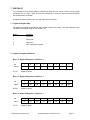
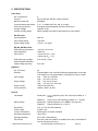
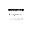
EMERALD-MM-OPTO
PC/104 Module with 2 or 4 Opto-Isolated RS-232/422/485 Ports
+ 24 Lines of Digital I/O
User Manual V1.02
Document no. 765320 Rev A
© Copyright 2004
DIAMOND SYSTEMS CORPORATION
8430 Central Ave.
Newark, CA 94560
Tel (510) 456-7800
Fax (510) 456-7878
[email protected]
http://www.diamondsystems.com/
TABLE OF CONTENTS
1.
DESCRIPTION .....................................................................................................................................3
2.
FEATURES............................................................................................................................................3
3.
SERIAL PORT ISOLATION...............................................................................................................3
4.
MECHANICAL DRAWING................................................................................................................4
5.
I/O HEADER PINOUTS.......................................................................................................................5
6.
BOARD CONFIGURATION...............................................................................................................7
7.
DIGITAL I/O .......................................................................................................................................12
8.
SPECIFICATIONS .............................................................................................................................14
© 2004 Diamond Systems Corp.
Emerald-MM-Opto User Manual V1.0
Page 2
EMERALD-MM-OPTO
PC/104 Module with 2 or 4 Opto-Isolated RS-232/422/485 Ports + 24 lines of Digital I/O
Models:
EMM-OPT2-XT
EMM-OPT4-XT
2 serial ports + 24 digital I/O
4 serial ports + 24 digital I/O
1. DESCRIPTION
Emerald-MM-OPTO is a PC/104 format I/O module with 2 or 4 optoisolated serial ports, 24 lines of
digital I/O, and extended temperature operation. Each serial port can be individually configured for
RS-232, RS-422 or RS-485. The digital I/O is provided by a standard 82C55 chip with 3 8-bit ports
and programmable direction. It is supported by Diamond Systems’ Universal Driver software for DOS,
Linux, QNX, and Windows.
Eight different I/O address combinations can be selected, and 9 different interrupt levels can be
assigned to configure each port, allowing operation as COM1 through COM4 as well as many other
settings. Four I/O headers are provided, one serial port on each header. The board operates on +5V
only, eliminating the need for a +12V supply that is often required for serial port operation.
The serial ports are based on the Exar ST16C2850 dual UART IC. This device contains 2 identical
sets of registers, one for each port, and is compatible with the standard PC serial port and most
popular operating systems. It offers an expanded 128-byte FIFO for RX and TX to support higher
baud rates as well as an auto-flow feature to control the transmitter during RS-485 half-duplex
communications.
2. FEATURES
♦
♦
♦
♦
♦
♦
♦
♦
♦
♦
2 or 4 serial ports based on 16C2850 UART (1 or 2 UART chips)
Galvanic isolation port-to-port and port-to-board, up to 1000V AC or DC
RS-232, RS-422, and RS-485 protocols
Protocols individually selected with jumpers for each port
Termination resistors individually selected with jumpers for each port
Jumper-selected I/O address and IRQ settings
24 digital I/O lines using 82C55
+5V only power supply
PC/104 format for rugged, compact design
Operating temperature -40 to +85oC
3. SERIAL PORT ISOLATION
The four serial ports are galvanically isolated from each other and from the rest of the board. The
isolation barrier is maintained via HCPL0630 optocouplers for the signals and a DCR010505U
isolating DC/DC converter IC. One DC/DC converter chip is used for each serial port circuit. Each
DC/DC converter is bypassed with a 10uF capacitor on both the input and output sides.
The ground and power planes for each serial port circuit’s section on the board are separated from
the main board ground and power planes with an isolation barrier of minimum 0.060”. No traces from
any isolated section exceed the boundary of that section’s area. No traces from the non-isolated
circuit cross into any isolated section.
In special configurations, the four isolated grounds can be connected to the main ground via a 3MΩ
resistor chain and/or a 220pF high-voltage capactor. These components will withstand and maintain
up to 1KV isolation. Contact Diamond Systems regarding these customizations.
© 2004 Diamond Systems Corp.
Emerald-MM-Opto User Manual V1.0
Page 3
4. MECHANICAL DRAWING
Description of Key Elements
J1
J2
J3
J4
J5
J6
J7
J8
PC/104 bus 8-bit bus header
PC/104 bus 16-bit bus header
Digital I/O
Serial port 1
Serial port 2
Serial port 3
Serial port 4
Address selection, baud rate
selection, RTS flow control
J9
J10
J11
J12
J13
J14
J15
J16
Serial port 4 IRQ selection
Serial port 3 IRQ selection
Serial port 2 IRQ selection
Serial port 1 IRQ selection
Serial port 1 configuration & termination
Serial port 2 configuration & termination
Serial port 3 configuration & termination
Serial port 4 configuration & termination
Jumper positions shown above are default settings. See chapter 6 for complete details on jumper
configuration.
© 2004 Diamond Systems Corp.
Emerald-MM-Opto User Manual V1.0
Page 4
5. I/O HEADER PINOUTS
5.1 Serial Port Connectors J4, J5, J6, J7
Each serial port has its own 10-pin (2x5) header with the following pinouts. Diamond Systems’ cable
no. C-DB9M-1 may be used for each port (qty 2 or 4 per board) to provide a standard male DB9
connector. In RS-232 mode, the pinout conforms to the PC standard for a 9-pin DTE (Data Terminal
Equipment) serial port.
(NC = No Connection)
RS-232 Configuration:
NC
RXD
TXD
NC
ISO GND
1
3
5
7
9
2
4
6
8
10
NC
RTS
CTS
NC
NC
RXD+
RXDTXD+
TXDISO GND
1
3
5
7
9
2
4
6
8
10
CTSRTS+
CTS+
RTSNC
TXD+/RXD+
TXD-/RXDTXD+/RXD+
TXD-/RXDISO GND
1
3
5
7
9
2
4
6
8
10
NC
NC
NC
NC
NC
RS-422 Configuration:
RS-485 Configuration:
In RS-485 mode, only one pair of signal wires is used, plus ground reference. Either pins 1 and 3 or
pins 5 and 7 may be used. These signal pairs are duplicated on the connector due to the jumpering
of the RX and TX lines on the configuration jumper block.
© 2004 Diamond Systems Corp.
Emerald-MM-Opto User Manual V1.0
Page 5
Signal Definitions:
Signal Name
RS-232:
RXD
RTS
TXD
CTS
Definition
Direction
Receive Data
Request To Send
Transmit Data
Clear To Send
Input
Output
Output
Input
RS-422:
TXD+, TXDRXD+, RXD-
Differential Transmit Data
Differential Receive Data
Output
Input
RS-485:
TXD/RXD+
TXD/RXD-
Differential Transmit/Receive +
Differential Transmit/Receive -
Bi-directional
Bi-directional
Common to all protocols:
GND
Ground
NC
Not Connected
---
5.2 Digital I/O – J3
The digital I/O is provided on a 26-pin (2x13) pin header with the following pinout. This connector may
be used with Diamond Systems’ cable no. C-26-18, which provides a 26-pin female connector at
each end.
C7
C5
C3
C1
B7
B5
B3
B1
A7
A5
A3
A1
+5V
© 2004 Diamond Systems Corp.
1
3
5
7
9
11
13
15
17
19
21
23
25
2
4
6
8
10
12
14
16
18
20
22
24
26
C6
C4
C2
C0
B6
B4
B2
B0
A6
A4
A2
A0
GND
Emerald-MM-Opto User Manual V1.0
Page 6
6. BOARD CONFIGURATION
Several features are jumper-configurable. All configuration jumpers are dual-row 2mm size. Provision
is made on the board for zero-ohm resistors to replace jumpers to enable a hard-wired configuration.
♦
Serial ports 1- 4: address combination (8 address combinations made possible with 3
jumpers providing a 3-bit binary selection)
♦
Serial port IRQ levels
♦
Serial port protocols
♦
RS-422/RS-485 termination resistors
♦
Digital I/O base address (4 address options with 2 jumpers)
♦
Baud rate x4/x1 selection
♦
RTS flow control in RS-485 mode
6.1 Baud rate clock selector – J8
On the I/O address jumper block, position CK is used to select between 1X and 4X baud rate. When
the jumper is out, the 7.3728MHz on-board oscillator is divided by 4 to provide a standard 1.8432MHz
clock to the UARTs, with a maximum baud rate of 115.2kbps in all protocols. When the jumper is in,
the 7.3728MHz is passed directly to the UARTs to enable up to 460.8kbps.
To be baud compatible with third party serial ports, you must leave the CK jumper out.
Note that in RS-232 mode, the fastest baud rate supported by the SP334 transceiver is 230.4kbps. In
RS-422/485 mode the transceiver will operate up to 460.8kbps.
6.2 RTS flow control – J8
Each UART (2 ports) may be configured so that RTS signal control the TXD transmitter. This features
is controlled with the HDCNTL- pin on the UART. This feature may be used in RS-485 mode to
automatically control the transmitter without requiring software. When data is ready to transmit, RTS
goes low, and when transmission is complete RTS goes high again. To use this function, both ports
must be configured the same way since only one input is provided for both ports.
RTS flow control is configured with the address configuration jumper block. To enable RTS flow
control for ports 1 and 2, insert a jumper in the 12 position. To enable RTS flow control for ports 3 and
4, insert a jumper in the 34 position.
© 2004 Diamond Systems Corp.
Emerald-MM-Opto User Manual V1.0
Page 7
6.3 Serial Port and Interrupt Register Address Selection – J8
The serial ports utilize 5 I/O address blocks in the PC’s I/O memory space:
1.
2.
3.
4.
5.
Serial port 1 (8 bytes)
Serial port 2 (8 bytes)
Serial port 3 (8 bytes)
Serial port 4 (8 bytes)
Serial port interrupt status register (1 byte)
The I/O addresses and baud rate clock selector are combined onto a single jumper block.
The I/O addresses are set with jumper block J8, or with 0-ohm resistors located at the bottom center
of the board. Eight different I/O address combinations are selectable for the serial ports. The address
shown below for each port is the base address (in hex) of that port, i.e. the lowest address of the
port’s I/O address block.
A
B
C
Port 1
Port 2
Port 3
Port 4
Interrupt
Status
In
In
In
3F8
2F8
3E8
2E8
220
Out
In
In
3E8
2E8
3A8
2A8
220
In
Out
In
380
388
288
230
224
Out
Out
In
240
248
260
268
224
In
In
Out
100
108
110
118
240
Out
In
Out
120
128
130
138
244
In
Out
Out
140
148
150
158
248
Out
Out
Out
160
168
170
178
24C
6.4 Digital I/O Addresses – J8
The 82C55 IC occupies 4 bytes of I/O space, selected by the D and E jumpers of J8 or by using the
corresponding 0-ohm resistors. All addresses are in hex.
D
E
Address
In
In
200-203
Out
In
240-243
In
Out
280-283
Out
Out
300-303
© 2004 Diamond Systems Corp.
Emerald-MM-Opto User Manual V1.0
Page 8
6.5 Serial protocol selection and configuration – J13, J14, J15 and J16
The serial ports are configured with 4 jumper blocks, one for each port. The jumper blocks have the
following functions:
Position
Name
Function
1
232
In = RS-232, out = RS-422/RS-485
2
RTS Ctrl
In = RTS controls TX transceiver in RS-485 mode
Out = TX transceiver is always enabled
3
Echo
In = TX enable causes RX disable to prevent echo during
transmission
Out = RX is always enabled
4
TXD Term
In enables TXD termination
5
RXD+ Term
In enables RXD high side termination / bias
6
RXD- Term
In enables RXD low side terminatoin / bias
7
RTS Term
In enables RTS termination
8
CTS+ Term
In enables CTS high side termination / bias
9
CTS- Term
In enables CTS low side terminatoin / bias
10
TX/RX+
Connect TX+ and RX+ for half-duplex 2-wire operation
11
TX/RX-
Connect TX- and RX- for half-duplex 2-wire operation
RS-232 Operation
Position 1 is in, and all other positions are out. RX and TX are used. RTS and CTS may optionally be
used.
RS-422 Operation
Positions 1, 2, 3, 10, and 11 are out. Positions 4-9 may be used as needed for termination / bias
functions. In RS-422 mode, both RXD and TXD twisted pairs are used, and RTS/CTS pairs may
optionally be used.
RS-485 Operation
Position 1 is out, and positions 2, 10 and 11 are in. If auto-485 mode (UART controls RTS line
automatically in hardware) is desired, set the appropriate jumper (12 or 34) on J8. If local echo is not
desired, install a jumper in position 3.
In RS-485 mode, only one pair RX/TX+ and RX/TX- are used, plus signal reference. In this mode,
jumpers 2 and 3 may be used for RTS flow control and echo prevention during transmission.
Positions 5 and 8 enable a 1K pull-up failsafe resistor on the RXD+ and CTS+ lines respectively.
Positions 6 and 9 enable a 1K pull-down failsafe resistor on the RXD- and CTS- lines respectively.
RS-422 / RS-485 Cable Endpoint Termination
In RS-422 or RS-485 networks, termination resistors are normally installed at the endpoints of the
cables to minimize reflections on the lines. Emerald-MM-OPT4-XT provides 150Ω resistors for this
purpose. To enable resistor termination, install jumpers in the locations 4-9 of J13, J14, J15, or J16
(for ports 1 – 4, respectively). Termination is only needed, and should only be used, at the cable
endpoints. Installing termination resistors at additional points in the network may cause overloading
and failure of the line drivers due to the lower impedance caused by multiple resistors in parallel.
© 2004 Diamond Systems Corp.
Emerald-MM-Opto User Manual V1.0
Page 9
6.6 Interrupt Levels – J9, J10, J11, J12
Each serial port has its own IRQ level selection jumper block:
♦
♦
♦
♦
COM1 IRQ = J12
COM2 IRQ = J11
COM3 IRQ = J10
COM4 IRQ = J9
Ports may have independent IRQs or they may share IRQs in any combination, depending on the
configuration.
The available IRQ levels for each port are 2, 3, 4, 5, 6, 7, 10, 12, and 15.
Interrupt Pulldown Resistor
In order to guarantee valid logic levels on the line when the device is not requesting service, each
active interrupt level requires a 1KΩ pulldown resistor. Only one such resistor should be used on
each active interrupt line. Each interrupt configuration header on Emerald-MM-OPT4-XT has a
position marked “R” for enabling the pulldown resistor. Install a jumper in this position to connect the
resistor, and remove the jumper to disconnect the resistor. If two or more ports are sharing the same
interrupt level, install the jumper in the R position for any one of the ports and leave it off the others.
Interrupt Sharing
On the PC/104 bus, interrupt levels may be shared by multiple devices. For this reason, the interrupt
is driven to a logic high level by the device requesting service, and when the device is serviced it tristates the line rather than driving it low. This technique avoids contention by two devices trying to
drive the line with opposing logic levels.
Interrupt Status Register
The interrupt status register (see section 7.3 for I/O location) indicates the status of each port’s
interrupt request line. It operates regardless of whether interrupt sharing is enabled (see above). If
two or more ports are sharing the same interrupt level, the status register will still indicate the correct
status of each port’s interrupt request line.
Bit No.
7
6
5
4
3
2
1
0
Name
X
X
X
X
INT4
INT3
INT2
INT1
Definitions:
X
Bit not used; reads back as a 0
INT4-1
Status of interrupt request for each port:
0 = no interrupt request active for this port
1 = interrupt request active for this port
© 2004 Diamond Systems Corp.
Emerald-MM-Opto User Manual V1.0
Page 10
6.7 Default Settings
The default settings for Emerald-MM-Opto are as follows:
Protocol settings:
All ports set for RS-232
Address/Interrupt settings:
(J7 A B C = In In Out):
Feature
Port 1
Port 2
Port 3
Port 4
Interrupt Status
Address
100
108
100
108
240
© 2004 Diamond Systems Corp.
Interrupt level
3
3
3
3
Emerald-MM-Opto User Manual V1.0
Page 11
7. DIGITAL I/O
24 TTL digital I/O lines are provided by a 82C55 chip. Each line can source 2.5mA in a logic 0 state
and sink 2.5mA in a logic 1 state. I/O lines are unbuffered, i.e. there is a direct connection between
the 82C55 and the I/O header.
All digital I/O lines are pulled up to +5V with 10KΩ pull-up resistors.
7.1 Digital I/O Register Map
The digital I/O provided by the 82C55 chip occupies 4 bytes of I/O space. The base address for this
I/O space is configured using J8 (see section 7.4).
Base +
Function
0
DIO port A
1
DIO port B
2
DIO port C
3
DIO configuration register
7.2 Digital I/O Register Definitions
Base + 0: Digital I/O Register A, 82C55 no. 1
Bit
Name
A7-A0
7
6
5
4
3
2
1
0
A7
A6
A5
A4
A3
A2
A1
A0
Digital I/O port A
Base + 1: Digital I/O Register B, 82C55 no. 1
Bit
Name
B7-B0
7
6
5
4
3
2
1
0
B7
B6
B5
B4
B3
B2
B1
B0
Digital I/O port B
Base + 2: Digital I/O Register C, 82C55 no. 1
Bit
Name
C7-C0
7
6
5
4
3
2
1
0
C7
C6
C5
C4
C3
C2
C1
C0
Digital I/O port C
© 2004 Diamond Systems Corp.
Emerald-MM-Opto User Manual V1.0
Page 12
Base + 3: Digital I/O Configuration Register
This control register determines the direction and mode of the 82C55 digital I/O lines.
Most applications use the simple I/O configuration, in which bit 7 is set to 1 and the Mode is set to 0
for all ports. Only the port direction bits need to be set.
For more complex operations with handshaking, concult the 82C55 datasheet attached at the end of
this manual.
Here is a list of common configuration register control bytes:
Configuration Byte
Hex
9B
Decimal
155
Port A
Input
Port B
Input
Port C (both halves)
Input
92
146
Input
Input
Output
99
153
Input
Output
Input
90
144
Input
Output
Output
8B
139
Output
Input
Input
82
130
Output
Input
Output
89
137
Output
Output
Input
80
128
Output
Output
Output
© 2004 Diamond Systems Corp.
Emerald-MM-Opto User Manual V1.0
Page 13
8. SPECIFICATIONS
Serial Ports
No. of serial ports:
Protocol:
Maximum baud rate:
Communications parameters:
Short circuit protection:
Isolation Voltage:
4
RS-232, RS-422, RS-485; Jumper selected
460.8kbps
5, 6, 7, or 8 data bits; Even, odd, or no parity
All outputs protected against continuous short circuit
1000VDC or AC
Isolation coupling option:
3MΩ in parallel with 220pF (consult factory for more details)
RS-232 mode:
Input impedance:
3KΩ min
Input voltage swing:
±30V max
Output voltage swing:
±5V min, ±7V typical
RS-422, RS-485 modes:
Differential input threshold:
-0.2V min, +0.2V max
Input impedance:
Input current:
12KΩ min
+1.0mA max (VIN = 12V)
-0.8mA max (VIN = -7V)
Differential output voltage:
High/low states differential
output voltage symmetry:
2.0V min (RL = 50Ω)
0.2V max
Digital I/O
No. of I/O lines:
Direction:
Input voltage:
Output voltage:
24
Programmable: Ports A and B individually programmable for all input
or all output. Port C programmable in 4-bit groups for input or output.
Low
-0.5V min, 0.8V max
High
2.0V min, 5.5V max
Low
0.0V min, 0.4V max
High
3.0V min, Vcc - 0.4V max
Output current:
±2.5mA max, each line
Pull-up resistors:
10KΩ to +5VDC, all lines
General
I/O headers:
Mating cables:
Dimensions:
Power supply:
Current consumption:
Operating temperature:
Operating humidity:
PC/104 bus:
© 2004 Diamond Systems Corp.
Serial ports: 2 or 4 10-position (2x5) .025” square pin header on .1”
centers
Digital I/O:
26-pin (2x13) .025” square pin header on .1” centers
Serial ports: Diamond Systems no. C-DB9M-1 (one per port)
Digital I/O:
Diamond Systems no. C-26-18
3.55” x 3.775” (PC/104 standard)
+5VDC ±10%
80mA typical, all outputs unloaded
-40 to +85oC
5% to 95% noncondensing
8 bit and 16-bit bus headers are installed and used (16-bit header is
used for interrupt levels only)
Emerald-MM-Opto User Manual V1.0
Page 14