1
Kongsberg Maritime
Doc.no.: SO-1342-F / 8-Nov-12
Engine Room Simulator
ERS L11 5L90MC – VLCC
Version MC90-V
Operator’s Manual
Part 3
Machinery & Operation
ERS MAN B&W 5L90MC-L11 Machinery & Operation MC90-V
Kongsberg Maritime
Doc.no.: SO-1342-F / 8-Nov-12
TABLE OF CONTENTS
Section
Page
1
SEQUENCE DIAGRAMS ................................................................ 2
1.1 First start to own supply ........................................................ 2
1.2 Own supply to harbour condition ............................................. 3
1.3 Harbour condition to ready for departure ................................. 4
1.4 Manoeuvre mode to sea passage mode .................................... 5
2
ELECTRICAL PLANT ................................................................... 7
2.1 Electrical Power Plant MD70 .................................................... 7
2.2 Diesel Generators MD75 ....................................................... 13
2.3 Synchroscope MD142 .......................................................... 19
2.4 Shaft Generator/Motor MD77 ................................................ 21
2.5 Main Switchboard-Starter section MD71 ................................. 25
2.6 Main Switchboard-Feeder section MD72 ................................. 27
2.7 Emergency Switchboard MD73 .............................................. 29
3
MAIN ENGINE AND MAIN ENGINE SYSTEMS .................................. 31
3.1 Main Engine........................................................................ 31
3.2 ME Lubrication Oil System MD12 ........................................... 35
3.3 ME Bearings MD29 .............................................................. 39
3.4 ME Cylinders MD21.............................................................. 43
3.5 ME Piston Ring Monitor MD27 ............................................... 45
3.6 Fresh Water Cooling System MD10 ........................................ 47
3.7 Fuel Oil System MD11 .......................................................... 51
3.8 ME Fuel Oil High Pressure System MD28 ................................ 57
3.9 ME Turbocharger System MD13 ............................................ 59
3.10 ME Selective Catalytic Reduction MD14 .................................. 63
3.11 ME Local Control MD20 ........................................................ 67
3.12 ME Manoeuvring System MD18 ............................................. 71
3.13 Cylinder Indications MD120 .................................................. 75
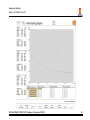
3.14 Load Diagram MD128 .......................................................... 85
4
PROPELLER AND STEERING GEAR SYSTEMS MD53 ......................... 89
4.1 Propeller Servo Oil System MD53 .......................................... 89
4.2 Stern Tube System MD54 ..................................................... 91
4.3 Steering Gear System MD58 ................................................. 93
5
SERVICE SYSTEMS ................................................................... 99
5.1 Main Sea Water System MD01 .............................................. 99
5.2 Air Ventilation System MD40 ............................................... 103
5.3 Air Conditioning Plant MD41 ................................................ 105
5.4 Starting Air Compressors MD59 ........................................... 109
ERS MAN B&W 5L90MC-L11 Machinery & Operation MC90-V
i
Kongsberg Maritime
Doc.no.: SO-1342-F / 8-Nov-12
5.5
5.6
5.7
5.8
5.9
5.10
5.11
5.12
5.13
5.14
5.15
5.16
5.17
5.18
5.19
5.20
5.21
5.22
5.23
5.24
5.25
5.26
Service Air Compressors MD60 ............................................ 113
Fuel Oil Transfer System MD03 ............................................ 117
Fuel Oil Service Tanks MD05 ................................................ 119
Fuel Oil Settling Tanks MD04 ............................................... 123
HFO Separator System MD06 .............................................. 127
Diesel Oil Separator System MD08 ....................................... 131
Lubrication Oil Purifier System MD09 .................................... 135
Fresh Water Generator MD61............................................... 139
Fresh Water Hydrophore System MD67 ................................. 143
Bilge System and Bilge Separator MD62 & MD63 .................... 144
Refrigeration System MD64 ................................................. 155
Sewage Treatment MD 45 ................................................... 159
Steam Generation Plant MD80 ............................................. 163
Exhaust Boiler MD81 .......................................................... 167
Oil Fired Boiler MD82 .......................................................... 169
Boiler Combustion MD84 ..................................................... 173
Steam Condenser MD85 ...................................................... 179
Turbo Generator MD86 ....................................................... 181
Cargo Pump Turbines MD87 ................................................ 185
Ballast Water System MD89 ................................................ 189
Inert Gas Plant MD91 ......................................................... 193
Deck Machinery MD97 ........................................................ 197
6
SIMULATOR & SHIP MODEL PARTICULARS .................................. 201
6.1 Propeller and Ship Model Characteristics ............................... 201
6.2 Ship Load MD57 ................................................................. 203
6.3 Ambient Temperatures ....................................................... 204
6.4 Auto Pulsar System ............................................................ 205
ii
ERS MAN B&W 5L90MC-L11 Machinery & Operation MC90-V
Kongsberg Maritime
Doc.no.: SO-1342-F / 8-Nov-12
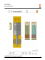
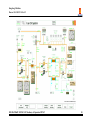
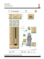
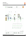
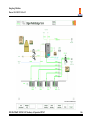
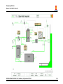
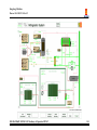
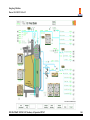
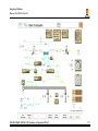
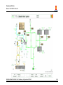
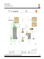
The Process diagrams presented on the monitors have the following colour codes for pipelines:
-
Blue:
Green:
Yellow:
Brown:
Light brown:
Grey:
Light blue:
Fresh water (low and high temperature)
Sea water
Diesel oil
Fuel oil
Lubrication oil
Start and service air
Steam
The Process Diagrams are abbreviated T, G, P, etc.; meaning:
T:
G:
P:
N:
Q:
I:
U:
F:
E:
V:
L:
X:
Z:
W:
Temperature
Flow
Pressure
Rpm
Power
Ampere
Voltage
Frequency
Electrical power
Valve
Level
Miscellaneous variable
Water or other undesirable contamination index variable
Viscosity
ERS MAN B&W 5L90MC-L11 Machinery & Operation MC90-V
1
Kongsberg Maritime
Doc.no.: SO-1342-F / 8-Nov-12
1
SEQUENCE DIAGRAMS
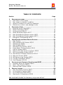
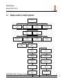
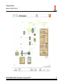
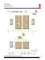
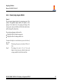
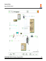
1.1
First start to own supply
Starting condition
(first start from cold ship)
Prepare/start Emergncy generator
(MD78) Ch. 2 - Sect. 2.1
Check all breakers closed on 220V main and emeg
boards
(MD72-73) Ch.2 - 2.6-2.7
Start fans
(MD40) Ch.2 - Sect. 5.2
Engage breakers on Emergency
Switchboard
(MD73) Ch.2 - Sect. 2.7
Fill emerg air receiver
(MD59) Ch.2 - Sect. 5.3
Own supply
Prepare/start aux. sea water system
(MD01) Ch.2 - Sect. 5.1
Prepare/start LT fresh water system
(MD10) Ch.2 - Sect. 3.6
Prepare/start #1 or #2 diesel alternato, and
connect to 440V board
(MD75/76) Ch.2 - Sect. 2.1-2.2
Engage breakers on main switchboard
starters and feeders
(MD71/72) Ch.2 - Sect. 2.5-2.6
ERS MAN B&W 5L90MC-L11 Machinery & Operation MC90-V
2
Kongsberg Maritime
Doc.no.: SO-1342-F / 8-Nov-12
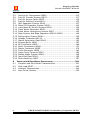
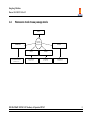
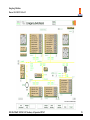
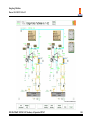
1.2
Own supply to harbour condition
Own supply
Check/conn. breakers on
440V feeder panel (MD72)
Ch.3 - Sect. 2.6
Prepare/operate aux LTFW/HTFW
system (MD10)
Ch.3 - Sect. 3.6
Prepare/operate start air compressor
1 & 2 (MD59)
Ch.3 - Sect. 5.3
Prepare/operate service air compressor
(MD60)
Ch.3 - Sect. 5.4
Prepare/operate
refrigeration plant (MD64)
Ch.3 - Sect. 5.13
Prepare/operate
Fresh water hydrophore plant (MD67)
Ch.3 - Sect. 5.13
Operate MELO purifier
(MD09)
Ch.3 - Sect. 5.10
Prepare HFO sett/serv
tanks (MD04/05)
Ch.3 - Sect. 5.6-5.7
Prepare/Operate oil fired boiler
on MDO/HFO (MD80~84)
Ch.3 - Sect. 5.14-5.17
Prepare/operate HFO separator
system (MD06)
Ch.3 - Sect. 5.8
Operate ME HTFW preheat
system (MD10)
Ch.3 - Sect. 3.6
Prepare/operate HFO supply
system (MD11)
Ch.3 - Sect. 3.7
Change over diesel alternator
to HFO (MD75/76)
Ch.3 - Sect. 2.1-2.2
Set up bilge system
for bilge tank (MD61/62)
Ch.3 - Sect. 5.12
Habour condition
ERS MAN B&W 5L90MC-L11 Machinery & Operation MC90-V
3
Kongsberg Maritime
Doc.no.: SO-1342-F / 8-Nov-12
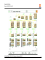
1.3
Harbour condition to ready for departure
Harbour condition
Prepare/start ME LO
system (MD12)
Ch.3 - Sect. 3.2
Prepare/start/parallel second
diesel alternator (MD75/76)
Ch.3 - Sect. 2.1-2.2
Prepare/start ME camshaft LO system
(MD12)
Ch.3 - Sect. 3.2
Prepare ME cylinder LO
system (MD12)
Ch.3 - Sect. 3.2
Prepare/start ME SW
system (MD01)
Ch.3 - Sect. 5.1
Prepare ME turbocharger
system (MD13)
Ch.3 - Sect. 3.9-3.10
Prepare/Operate exh gas boiler circulating
pumps (MD82)
Ch.3 - Sect. 5.14
Prepare/Test steering gear
system (MD58)
Ch.3 - Sect. 4.3
Test emergency telegraph
(MD104/110)
Ch. 2 - Sect. 1.2, 5.1
Prepare/start HTFW cooling
water systems - (MD10)
Ch.3 - Sect. 3.6
Prepare/Operate stern tube
system (MD54)
Ch.3 - Sect. 4.2
Turn ME on turning gear
(MD20)
Ch.3 - Sect. 3.11
Remove Turning gear and close indicator
cocks (MD20)
Ch.3 - Sect. 3.11
Place all pumps and fans in standby mode
(MD102)
Ch.2 - Sect. 2.2
Place aux blowers in automatic and
start(MD20/102)
Ch.3 - Sect. 3.6
Test engine ahead and astern
(MD104/110)
Ch. 2 - Sect. 1.2, 5.1
Stop main engine pre-heating when
temperature > 65 C
(MD10)
Ch.3 - Sect. 3.6
Connect/start bow thrusters
(MD71/111)
Ch.2 - Sect. 5.2 / Ch.3 - Sect. 2.5
Open air to ME from air receivers (MD59)
Ch.3 - Sect. 5.3
Unblock valves within manouvring system
(MD18)
Ch.3 - Sect. 3.12
ERS MAN B&W 5L90MC-L11 Machinery & Operation MC90-V
Accept standby engine
(MD104/110)
Ch.2 - Sect. 1.2, 5.1
Ready for departure
4
Kongsberg Maritime
Doc.no.: SO-1342-F / 8-Nov-12
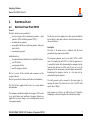
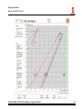
1.4
Manoeuvre mode to sea passage mode
Manoeuvre
Propulsion plant Operation mode
(Sea passage mode)
Combinator mode
Select Combinator mode from the main
engine AutoChief control panel
Ch.2 - Sect. 1.1-1.2
Economy mode
Fixed pitch
Fixed speed
Select fixed Pitch from
Ch. 2 - Sect. 1.1-1.2
Select Fixed Speed
Ch. 2 - Sect. 1.1-1.2
ERS MAN B&W 5L90MC-L11 Machinery & Operation MC90-V
Select Economy mode from the main engine
AutoChief control panel
Ch. 2 - Sect. 1.1-1.2
5
Kongsberg Maritime
Doc.no.: SO-1342-F / 8-Nov-12
ERS MAN B&W 5L90MC-L11 Machinery & Operation MC90-V
6
Kongsberg Maritime
Doc.no.: SO-1342-F / 8-Nov-12
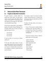
2
ELECTRICAL PLANT
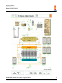
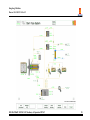
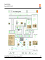
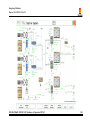
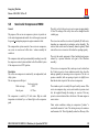
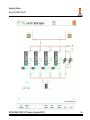
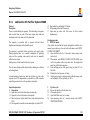
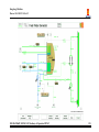
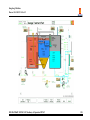
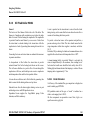
2.1
Electrical Power Plant MD70
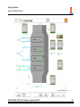
General
The ship’s electric power is generated by:
two diesel engine driven synchronous generators - diesel
generator 1 (DG1) and diesel generator 2 (DG2 )
one turbine driven generator.
one propeller shaft driven synchronous generator, with power
take in facility.
one emergency generator
and distributed via:
one main switchboard, divided into two main 440V bus bars
one 220v bus bar
one emergency bus bar
one 220v emergency bus bar
Bus bar 1 powers all the electrical main consumers and the
emergency bus bar.
Bus bar 2 powers the bow thruster and the heavy deck machinery.
The 220v bus bar is supplied from bus bar 1 via a circuit breaker
and transformer.
The emergency switchboard supplies the emergency 220v bus bar
via a circuit breaker and transformer. Emergency batteries are
supplied by two battery chargers, one for starting battery and one
for emergency supplies.
ERS MAN B&W 5L90MC-L11 Machinery & Operation MC90-V
The bus bars can also be supplied via a shore connection link that
has the ability to alter phase rotation to ensure that motors turn in
the correct direction.
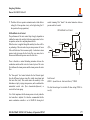
Description
The status of all prime movers is indicated, with the diesel
generators having a remote start available.
The emergency generator can be set to either AUTO or MAN
mode. It is normally kept in AUTO. Test 1 starts the generator, test
2 connects the breaker while disconnecting the emergency bus bar
from the main bus bar. In AUTO mode if power is lost to the
emergency bus bar the generator starts and connects automatically.
Reconnecting the emergency bus bar to a live main bus bar
automatically stops the generator.
The shaft generator can be connected to the main engine by
operating the clutch. The clutch will not close if the PTI shaft
speed is above 300rpm.
Each generator is excited by an AVR based on a PI controller.
Changing the excitation setting alters the controller base setting.
7
Kongsberg Maritime
Doc.no.: SO-1342-F / 8-Nov-12
Each main generator has indication for rotor phase (between
current and voltage), current angle, power factor and reactive
power.
The main generators governor speed control and shaft generator
load control can be accessed. All are based on a PI controller with
droop setting.
Normal operating modes.
The shaft generator can be used as a power take in (motor) in case
of main engine problems so that propulsion can be maintained.
-
All main generators are protected by a circuit breaker. The breaker
protects against:
Fast overload
Slow overload
Reverse power
Low voltage
Low frequency
The settings of the above are easily accessed on the breaker itself.
The breaker also sets the level at which the preferential trips
operate, this function does not trip the circuit breaker. Whichever
trip has activated is indicated and can be reset from the circuit
breaker. The emergency generator can not be synchronised, its
breaker are accessed via variables page 7822.
Emergency generator on AUTO at all times.
In port.
diesel generators supplying power as required,
normally one is sufficient.
-
Manoeuvring.
Fixed pitch operation.
both diesel generators supplying all electrical
power.
Variable pitch operation.
both diesel generators supplying main bus
bus tie open
Shaft generator supplying power to bow thruster.
Sea passage
Turbine generator supplying all power
Shaft generator in PTI
Turbine out of action
Shaft generator supplying all power.
On the main bus bar there is a connection to the emergency bus
bars, a bus tie for main deck machinery and a shore connection
availability.
ERS MAN B&W 5L90MC-L11 Machinery & Operation MC90-V
8
Kongsberg Maritime
Doc.no.: SO-1342-F / 8-Nov-12
Operation
1. Shore Connection.
1.1 Ensure all generators disconnected, emergency bus bar and
bus tie disconnected.
1.2 Connect incoming cable.
1.3 Check phase rotation, use phase twist if required.
1.4 Close shore circuit breaker to supply main bus.
1.5 Close emergency bus if required or starting from cold and
continue start sequence.
1.6 Shore circuit breaker must be tripped before connecting main
generator to bus.
2.
2.1
2.2
2.3
2.4
2.5
2.6
2.7
Emergency Generator Starting
Ensure battery voltage is correct. MD73 or 78. V72691.
If battery voltage to low, use the EM hydraulic start.
Generator in manual operation press start.
Turn on voltage control and adjust to 440v.
Use governor control to give 60Hz output.
Connect emergency generator breaker.
Trip main bus breaker connection to emergency bus.
3. Emergency Generator Stopping
3.1 Ensure that main bus bar has supply.
3.2 Connect main bus bar breaker connection to emergency bus.
3.3 Open emergency generator breaker.
3.4 Stop generator.
ERS MAN B&W 5L90MC-L11 Machinery & Operation MC90-V
4. Emergency Generator Automatic Operation
4.1 The generator is normally in AUTO, voltage control on,
circuit breaker open.
4.2 If supply is lost to the emergency switchboard the generator
will automatically start and close the circuit breaker
supplying the emergency bus.
4.3 The main bus will be isolated due to the connection circuit
breaker opening on low voltage.
4.4 When the emergency bus is again supplied from the main
bus, connection circuit breaker closed, the emergency
generator will automatically stop and open the circuit
breaker.
5. Emergency Generator Testing
5.1 The generator should be tested regularly to ensure that it will
function when required.
5.2 With the generator in AUTO, TEST 1 will simulate low
voltage on the emergency bus causing the generator to start.
5.3 The generator will attempt a maximum of three starts.
5.4 Releasing TEST 1 the generator stops.
5.5 Before using TEST 2 the bridge must be informed and check
that the elevator is not in use. TEST 2 will temporarily
interrupt the emergency supply.
5.6 TEST 2 disconnects the emergency bus from the main bus
simulating total supply failure, the generator starts and
supplies the emergency bus.
5.7 Releasing TEST 2 reconnects the emergency bus to the main
bus and the generator stops.
9
Kongsberg Maritime
Doc.no.: SO-1342-F / 8-Nov-12
6. Main Generators
6.1 It is normal to have the generators in AUTO, (MD101), and
priorities set on shaft and diesel generators so that load sharing
is achieved as the control mode dictates.
6.2 The Turbo generator will always be priority one when
running.
6.3 With generators not in AUTO mode connection can be made
from MD70.
6.4 Before attempting connection check that the generator is ready
to run. (MD75, MD76, MD86).
6.5 The turbo alternator must be running before connection can be
attempted.
6.6 Ensure that voltage control is on.
6.7 Start required generator by pressing start/stop button.
6.8 When engine is running adjust voltage control if necessary to
match main bus voltage.
6.9 The breaker can be made by the semi auto sync – select
generator and adjust speed until ready light shows, press conn.
6.10 Manual synchronising can be carried out from the main
switchboard (MD140 – MD144).
6.11 Once connected the generators must be manually balanced by
adjusting the governor controls.
6.12 To disconnect select generator to be stopped, remove load by
lowering the governor control, press disc.
6.13 After disconnection, the generator can be stopped by pressing
the start/stop button.
6.14 The turbo generator must be stopped from MD86.
ERS MAN B&W 5L90MC-L11 Machinery & Operation MC90-V
7 Shaft Generator, Power Take Off mode
7.1 Ensure that the shaft generator is ready on MD77. Auxil.
Power, Synch. Cond. On and air valve open. Clutch control in
local.
7.2 Ensure voltage control is on.
7.3 Engage clutch. Clutch will not engage if input drive speed is
greater than 300 rpm.
7.4 Adjust voltage control if necessary.
7.5 Use Semi Auto Synch. to select SG and raise/lower load
control until ready light is on.
7.6 Press connect and raise load as required.
7.7 Manual synchronising can be carried out from the main
switchboard (MD140 – MD144)..
7.8 To disconnect, select SG, reduce load to zero and press Disc.
8 Shaft Generator, Power Take In mode
8.1 To enable power take in the reverse power setting of the
breaker is set to –1500kW.
8.2 Breaker must be connected in PTI mode.
8.3 Press PTI.
8.4 The shaft generator load is gradually reduced and PTI mode
initiated.
8.5 PTI may be adjusted using the Lower and Raise load control.
8.6 To change from PTI to PTO press PTO. Power in is reduced to
zero.
8.7 Disconnect breaker or adjust load to supply power from SG.
10
Kongsberg Maritime
Doc.no.: SO-1342-F / 8-Nov-12
<This page is intentionally left blank>
ERS MAN B&W 5L90MC-L11 Machinery & Operation MC90-V
11
Kongsberg Maritime
Doc.no.: SO-1342-F / 8-Nov-12
ERS MAN B&W 5L90MC-L11 Machinery & Operation MC90-V
12
Kongsberg Maritime
Doc.no.: SO-1342-F / 8-Nov-12
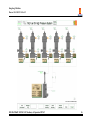
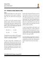
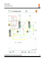
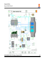
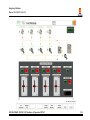
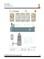
2.2
Diesel Generators MD75
General
The ship is equipped with two 900kW/850kVA/440V/60Hz/900
rpm synchronous main generators. Each generator is driven by a
turbocharged, four-stroke, 6-cylinder auxiliary diesel engine (DG1
and DG2)
The auxiliary diesel engines are equipped with separate, integrated
systems for cooling water and lubrication oil.
The diesel engines are designed for both diesel and heavy fuel oil
operation (700 cSt).
In order to prevent carbonising and heavy smoke emission during
low load, the fresh water cooling system is arranged in such a way
that the scavenge air is heated during low load.
Description
The engine is equipped with a shaft driven fuel oil pump. The
pump takes suction either from the fuel oil supply system or direct
from the diesel oil service tank. Shifting between diesel oil and fuel
oil is carried out by means of the double 3-way valve, shifting both
supply and return direction.
The piping from Fuel supply system (MD11) to the diesel
generators (MD75/76) can be heated by steam tracing and is also
kept hot by fuel recirculation at each generator. To keep the fuel
injection pumps hot, a non-return fuel circulation valve is mounted
in parallel with the fuel pump, also a pressure control valve in the
fuel return line is included. The fuel quality at injection pumps is
indicated. For a safe start the viscosity at injection pumps should
not be higher than 17-18 cSt. If a change-over is made from HFO
to DO while the engine is running, there will be a short loss of
ERS MAN B&W 5L90MC-L11 Machinery & Operation MC90-V
power, but the engine will keep running. A change-over to HFO
while the engine is running on DO will cause missfiring/engine
stop due to too low temperatures of the metal part in the fuel feeder
line and injection pumps. The fuel oil pump discharges to the highpressure pump header through a duplex filter. Surplus oil is
returned to the diesel oil service tank or the fuel oil system
depending on the position of the double 3-way valve.
An electrically operated shut-off valve on the suction side of the
fuel oil pump shuts off the fuel oil supply in case of an emergency.
The valve is controlled from the Remote Emergency Operating
Panel.
The lubrication system is equipped with an electrical oil pump and
a shaft driven main lubrication oil pump. The electrical pump
serves as a pre-lubrication oil pump and as a stand by oil pump in
case of break down of the shaft driven main pump. The pumps take
suction from the diesel engine lubricating oil sump and discharges
though a freshwater cooled oil cooler and a duplex filter. The oil
sump can be refilled from the lubricating oil storage and the oil can
be drained to the sludge tank by using the electrical oil pump.
The electrical oil pump can be operated in manual or in automatic
mode.
Seawater for the LT and HT fresh water coolers is provided by the
vessel’s main sea water system.
A shaft driven LT fresh water circulating pump circulates fresh
cooling water through the lubricating oil cooler and the scavenging
13
Kongsberg Maritime
Doc.no.: SO-1342-F / 8-Nov-12
air cooler. A shft driven HT fresh water circulating pump circulates
the scavenge air heater and cylinder jackets. The temperature is
controlled by a simple proportional controller, controlling the
temperature at inlet cylinder jackets. The HT can be pre-heated,
using an electric heater.
The governor (rpm controller) settings are available in a pop-up
window with the following variables:
-
-
Speed-droop (speed controller droop setting): Default setting
= 60%, which represents a speed droop approx. 3%, or
1.8Hz. 100 % = approx. 5% speed droop.
Speed set point (basic speed at unloaded engine): Default
setting = 909 rpm.
Load limit (speed controller max. Output limit): Default
setting for the “maximum fuel lever position” = 100%.
Compensation lever (speed controller gain): Default setting
for the proportional gain is set to 65.
Compensation valve (speed controller integral time): Default
setting = 20 seconds.
The governor response at different settings can be studied by
means of the pop-up TREND window.
NOTE!
Frequency regulation stops when the Engine is
overloaded (when alarm is activated).
The FW temperature controller is a proportional gain controller
with BIAS setting. BIAS default setting is 50%, which means that
50% is added. (Deviation * P-Gain) + BIAS = Output.
The pre-lubrication pump: Interval lubrication with default setting:
8 seconds on and 20 seconds off. The pre-lubrication pump will
ERS MAN B&W 5L90MC-L11 Machinery & Operation MC90-V
stop when the diesel starts, if lubrication oil pump control is set to
AUTO, and start when the diesel engine stops. The Engine Control
Panel has the following functions and indications:
Selection of local/remote control of engine
Start/stop of engine
Trip indications
Reset of trip
Safety System
The diesel engines are equipped with a separate, independent safety
system acting as a back-up system to the safety system of the
PowerChief. The system monitors the engine condition by binary
sensors and includes the following adjustable parameters:
Parameter
Over speed
Low Lub Oil Pressure
High Lub Oil Temp.
High fresh water Temp.
High Exhaust Temp.
Normal setting
112%
1,0 bar
90oC
96oC
700oC
If one of the parameters is exceeded the diesel engine will shut
down and a trip alarm is given. A lamp at the local panel indicates
the trip condition. To restart the engine the cause must be found
and corrected and the safety system must be reset by pushing the
RESET button.
The trip limits can be inspected and changed from the variable
page 7515/7615.
14
Kongsberg Maritime
Doc.no.: SO-1342-F / 8-Nov-12
Operation procedure
In normal operation the generator is in stand by mode with AUTO
and priority selected on the POWER CHIEF. While in AUTO
mode the generator must be prepared ready to start.
1. Preparation
1.1 Check level in the fresh cooling water expansion tank and
refill if necessary.
1.2 Check that the fresh water temperature controller is working
and in AUTO – normal set point is 85°C
1.3 Ensure sea water valve to cooler is open pump, MD01, and sea
water flow is normal.
1.4 Check level in lubricating oil sump tank, (min 40%) - refill
from storage tank if necessary
1.5 Line up lubrication oil system. Normally one filter is in
operation and one filter is cleaned and on stand-by.
1.6 Ensure that lubrication oil valve to the sludge tank is closed.
1.7 Start the electrically driven lubricating oil pump (prelubrication oil pump), and check that the oil pressure is
increasing.
1.8 Set the electrical lubricating oil pump in AUTO mode by
pressing the AUTO button on the PUMP. CTR. panel.
1.9 Check water level in the fuel oil service tanks and drain if
necessary.
1.10 Ensure that fuel oil supply valves from diesel oil service tank,
MD05, and fuel oil system, MD11, to generator engine are
open.
ERS MAN B&W 5L90MC-L11 Machinery & Operation MC90-V
1.11 Open fuel oil inlet valve to fuel oil pump.
1.12 Open fuel oil valve before fuel oil filters. Normally one filter
is in operation and one filter is cleaned and on stand-by.
1.13 Check the position of the fuel oil supply 3-way valve.
1.14 Open start air valves, MD59. Start air must be at least 15 bar
(218 psi) on the starting air line.
1.15 If any of the alarm lamps (red) at the local panel are lit, press
the RESET button.
1.16 Start the engine from the local panel by pressing the START
button.
2.
2.1
2.2
2.3
2.4
2.5
2.6
2.7
Starting
When the Engine Control panel is in Remote the engine can
only be started from the POWER CHIEF panel or Electric
Power Plant, MD70.
To start locally select local on the Engine Control Panel.
Start the Lubricating oil priming pump manually.
Press Start.
When engine is running, stop Lubricating oil priming pump
and set to AUTO.
The generator can now be connected to the main bus using
the Synchrchroscope panel, MD142, or Electric Power Plant
panel, MD70.
To use the POWER CHIEF the generator must be switched
to Remote.
15
Kongsberg Maritime
Doc.no.: SO-1342-F / 8-Nov-12
Stopping
3.1 The generator can be stopped when in AUTO from the
POWER CHIEF panel or the Electric Power Plant panel.
3.2 To stop locally, firstly ensure that generator breaker is open.
3.3 With the Engine Control in Local, press STOP.
ERS MAN B&W 5L90MC-L11 Machinery & Operation MC90-V
3.4
3.5
If the generator is to be stopped for maintenance, leave
control in Local and close starting air valve.
Placing the electric lubricating oil pump in manual prevents
start from remote positions.
16
Kongsberg Maritime
Doc.no.: SO-1342-F / 8-Nov-12
<This page is intentionally left blank>
ERS MAN B&W 5L90MC-L11 Machinery & Operation MC90-V
17
Kongsberg Maritime
Doc.no.: SO-1342-F / 8-Nov-12
ERS MAN B&W 5L90MC-L11 Machinery & Operation MC90-V
18
Kongsberg Maritime
Doc.no.: SO-1342-F / 8-Nov-12
2.3
Synchroscope MD142
1.6
General
The synchroscope panel is used for manual connection of the
generators to the bus bar.
1.7
Connect breaker when the top synschroscope indicator is lit.
The breaker connected light will show that the generator is
now connected to the bus.
Increase the governor speed to give the incoming generator
some load.
To manually share the load equally use the governor controls
on MD70 or on each generator page MD140/141/143/144.
The panel consists of selector switches for each generator and
indicates the voltage and frequency of the bus and of the selected
generator. A synchroscope indicates the phase relationship between
main bus and selected generator. There is also an indicator to show
that the selected generator is connected to the main bus.
1.8
The shore supply can be accessed from this panel.
2.2
The syncroscope can be accessed from the individual generator
sections of the main switchboard panels. (MD140 -144)
2.3
2.4
1. Connection
1.1 The incoming generator must be running and not in AUTO
on MD101.
1.2 Select incoming generator, voltage and frequency can be
compared with bus.
1.3 Adjust excitation if necessary to give equal voltages.
1.4 Adjust governor control so that incoming generator is slightly
faster than bus frequency.
1.5 Synchroscope indicator should be turning slowly in a
clockwise direction.
3. Shore Supply
3.1
To connect the shore supply the main bus must be dead
3.2
Connect the shore supply cable
3.3
Ensure phase rotation is correct
3.4
Close circuit breaker
3.5
The shore supply must be disconnected before resupplying
the main bus from the ships’ generators
ERS MAN B&W 5L90MC-L11 Machinery & Operation MC90-V
2.
2.1
Disconnection
Ensure generator to be disconnected is not in AUTO on
MD101
Use governor controls on MD70 or on each generator to
reduce the load on outgoing generator to zero.
Select outgoing generator.
Disconnect, breaker connected light goes out.
19
Kongsberg Maritime
Doc.no.: SO-1342-F / 8-Nov-12
ERS MAN B&W 5L90MC-L11 Machinery & Operation MC90-V
20
Kongsberg Maritime
Doc.no.: SO-1342-F / 8-Nov-12
2.4
Shaft Generator/Motor MD77
General
The shaft generator/motor system consists of the following main
components:
-
Control system
Static converter
Shaft generator/motor
Synchronous condenser
Smoothing reactor
The power from the shaft of the main engine drives the shaft
generator via a gear and a clutch. The clutch is driven by control air
and will not operate if the control air is missing. The clutch will not
engage if the inlet shaft speed is above 300rpm.
The Shaft Generator can supply the ship’s network with electrical
energy when SG is running above 200rpm. Between 200 and
400rpm the load is limited to half, above 400rpm maximum power
is available.
The synchronous condenser controls voltage and frequency.
Frequency is determined by condenser speed, voltage by a standard
AVC.
A load controller controls power flow through the static converter
by timing rectifying thyristors, it also controls the excitation of the
shaft generator.
ERS MAN B&W 5L90MC-L11 Machinery & Operation MC90-V
The shaft generator is designed for continuous parallel operation
with conventional auxiliary generators and exhaust gas turbogenerator sets.
The control panel supplies auxiliary power for the excitation
converter and cooling fan. The SG cannot operate if auxiliary
power is lost. The synchronous condenser is started from the
control cabinet. When starting the SC considerable power is drawn
from the main distribution supply.
The shaft generator can be used as a motor in Power Take In mode.
This enables excess available electrical power to be used to
supplement the main engine to give greater shaft output. In PTI
mode the motor can either use the available electrical capacity or
the maximum consumption can be manually selected. The
maximum load on the motor will always leave a reserve of 300kW.
Operation Procedure
Normal operation involves engaging the clutch at stand-by in order
that the generator may be used on passage.
During manoeuvring electrical power is supplied from the diesel
generators.
When the vessel is on passage the turbine generator is used in
parallel with the shaft generator.
21
Kongsberg Maritime
Doc.no.: SO-1342-F / 8-Nov-12
If there is available electrical capacity from the turbine generator
then the shaft generator may be used in PTI mode to increase
efficiency.
In case of main engine reduced power or if extra shaft power is
required the shaft generator can be used in PTI mode with the
diesel generators.
1. Starting shaft generator
1.1 Ensure auxiliary power on and cooling fan is running.
1.2 Check that enough reserve power is available to start
synchronous condenser, about 150kW.
1.3 Start synchronous condenser.
1.4 Open air valve to clutch.
1.5 Ensure input shaft speed below 300 rpm and connect clutch
in local control. When clutch has engaged change to remote
control.
3.4
To change to PTI select Generator Mode.
4. Stopping
4.1 It is normal to leave the clutch engaged when main engine is
running otherwise, in order to engage clutch, the engine
would have to be slowed down.
4.2 If the generator is not required, disconnect circuit breaker in
the normal manner.
4.3 The synchronous generator may now be stopped.
4.4 If maintenance is to be carried out it will be necessary to turn
off the auxiliary power, disengage the clutch and close the air
valve to the clutch.
2. Generator Mode
2.1 Normal mode is generator mode as indicated on the control
panel.
2.2 The generator can be connected manually or automatically
from the Power Chief panel in the normal manner.
3.
3.1
3.2
3.3
Power Take In
To use PTI the generator breaker must first be connected in
the normal manner.
PTI can be selected locally or from the Power Chief panel.
In PTI mode select either Available Mode to use all
available power (300kW will be in reserve) or select Setting
Mode where the motor power can be set up to a maximum
of 300Kw in reserve.
ERS MAN B&W 5L90MC-L11 Machinery & Operation MC90-V
22
Kongsberg Maritime
Doc.no.: SO-1342-F / 8-Nov-12
<This page is intentionally left blank>
ERS MAN B&W 5L90MC-L11 Machinery & Operation MC90-V
23
Kongsberg Maritime
Doc.no.: SO-1342-F / 8-Nov-12
ERS MAN B&W 5L90MC-L11 Machinery & Operation MC90-V
24
Kongsberg Maritime
Doc.no.: SO-1342-F / 8-Nov-12
2.5
Main Switchboard-Starter section MD71
General
The starters are grouped into four main sections. Deck machinery
and bow thruster are supplied via a bus tie.
Each starter group has indication for current, active power, reactive
power and power factor. Starters indicated with an asterix are
supplied from elsewhere and are not included in the calculations
for the starter group.
The breakers are operated by pressing the IN button. Pressing IN
again will open the breaker. The green indicator shows if the
machinery is running.
The display value of the breakers may be changed from active
power to current.
The starter circuit breakers can be individually grouped by setting
the function variable to one of eight settings.
1
OL trip only
2
OL trip and auto pump restart
3
OL trip and zero volts disconnection
4
OL trip and zero volts trip
11
Non Essential + 1
12
Non Essential + 2
13
Non Essential + 3
14
Non Essential + 4
The settings can be found on the CBR Doc variables.
Non Essentials trip as dictated by the settings on the generator
breakers on MD70.
Total Earth Leakage current is constantly monitored. Earth fault
finding is available by selecting 440v or 220v distribution system
and switching between phases.
In case of overload of available supply the breakers can be grouped
for non essentials to automatically disconnect. Non essentials must
be circuits not required for the safe operation of the vessel.
ERS MAN B&W 5L90MC-L11 Machinery & Operation MC90-V
25
Kongsberg Maritime
Doc.no.: SO-1342-F / 8-Nov-12
ERS MAN B&W 5L90MC-L11 Machinery & Operation MC90-V
26
Kongsberg Maritime
Doc.no.: SO-1342-F / 8-Nov-12
2.6
Main Switchboard-Feeder section MD72
General
The feeders are grouped into four main sections. The 220v
sections are fed from the main bus via a circuit breaker and
transformer.
The breakers are operated by pressing the IN button. Pressing IN
again will open the breaker.
The feeder circuit breakers can be individually grouped by
setting the function variable to one of eight settings.
1
OL trip only
2
OL trip and auto pump restart
3
OL trip and zero volts disconnection
4
OL trip and zero volts trip
11
Non Essential + 1
12
Non Essential + 2
13
Non Essential + 3
14
Non Essential + 4
The settings can be found on the CBR Doc variables.
The display value of the breakers may be changed from active
power to current.
Non Essentials trip as dictated by the settings on the generator
breakers on MD70.
Each feeder group has indication for current, active power,
reactive power and power factor. Feeders indicated with an
asterix supply elsewhere and are not included in the calculations
for the feeder group.
In case of overload of available supply the breakers can be
grouped for non essentials to automatically disconnect. Non
essentials must be circuits not required for the safe operation of
the vessel.
ERS MAN B&W 5L90MC-L11 Machinery & Operation MC90-V
27
Kongsberg Maritime
Doc.no.: SO-1342-F / 8-Nov-12
ERS MAN B&W 5L90MC-L11 Machinery & Operation MC90-V
28
Kongsberg Maritime
Doc.no.: SO-1342-F / 8-Nov-12
2.7
Emergency Switchboard MD73
General
The emergency switchboard supplies circuits necessary for the
safety of the vessel. These include communications, navigation
lights, fire alarm, fire and flood control.
The feeders are grouped into four main sections. Two 440v
sections and two 220v sections supplied via a circuit breaker and
transformer.
Each feeder group has indication for current, active power, reactive
power and power factor. Feeders indicated with an asterix supply
elsewhere and are not included in the calculations of the feeder
group.
The breakers are operated by pressing the IN button. Pressing IN
again will open the breaker.
The display value of the breakers may be changed from active
power to current.
Earth fault finding is available by selecting 440v, 220v or 24v dc
distribution system and switching the resistance meter between
phases.
The feeder circuit breakers can be individually grouped by setting
the function variable to one of eight settings.
1
OL trip only
2
OL trip and auto pump restart
ERS MAN B&W 5L90MC-L11 Machinery & Operation MC90-V
3
OL trip and zero volts disconnection
4
OL trip and zero volts trip
The settings can be found on the CBR Doc variables. The
emergency switchboard supplies are all essential and should not be
connected to non-essential trips.
The emergency batteries are supplied by battery chargers via the
440v emergency bus. There are two sets of batteries, one for
starting the emergency generator and one for the main 24v supply.
Terminal voltage of each battery is displayed.
2.7.1
Emergency Generator Back Feed Mode
The Emergency Switch Board (ESWB) and the Main Switch Board
(MSWB) can be connected in two different ways.
Normal Mode
The Emergency Switch Board is connected to the Main Switch
Board by a selection switch. If there is voltage on the Main Switch
Board the position is kept in “MSWB”. When the switch is
deactivated by loss of main voltage or by emergency generator
“test 2” override, the switch takes default position, “Emergency
Generator”. The selection switch functions as a safe guard against
overloading the Emergency Generator by mechanically isolating it
from the main bus.
29
Kongsberg Maritime
Doc.no.: SO-1342-F / 8-Nov-12
Optional Mode
If it is required that the Emergency Generator in critical situations
also should be able to feed the main bus system, the selection
switch must be exchanged with a bus-tie breaker with associated
bus-tie control logics. In addition the Emergency Generator must
be permanently wired for connection to the emergency bus bar.
Changing from Normal to Optional Mode is done by setting the
parameter C06136, on variables page 7005,to 1. The Optional
Mode is denoted “Back Feed Permit (USCG spec) Mode”
Operation procedure
In “Normal Mode” the bus-tie control is always fixed to “Auto”
and no manual override is accepted. The bus-tie control is then
simply representing the automatic positioning of the selector switch
by main bus voltage
In “Optional Mode” the bus-tie control logics function as follows:
Auto
At loss of main voltage the bus-tie breaker opens. At return of
voltage the emergency bus is de-energized, by disconnection of the
EG if connected, before the bus-tie breaker is reconnected to the
main bus. Activation of EG-test2 will “simulate” loss of main
voltage and make the bus-tie breaker disconnect.
the bus-tie control to be in “Auto”, transferring bus-tie control to
manual also disables automatic EG operation.
Even in “Manual” mode the bus-tie breaker is automatically
disconnected if loss of main bus power.
If there is voltage on the emergency bus, the connect (“In”)
command will not function, unless the “Back-Feed” override is
‘On’.
Back-Feed
Selection of bus-tie “Back-Feed” mode is protected by a key lock
etc, indicated by a red light when activated.
The bus-tie control will be fixed to “Manual” and the connectinhibit, which is normally active in “Manual”, is also disabled,
leaving the bus-tie to direct operator control.
Connection of the bus-tie should never be attempted when there is
voltage on both the main and the emergency switch board.
Note: When then the Emergency Generator is connected to the
Main Switch Board by Back-Feed it is easily overloaded. All
automatic start-up of equipment must be disabled before supplying
voltage to the main bus!
Manual
The main bus and the emergency bus can be split manually without
any restrictions by disconnecting the bus-tie breaker (“Out”
command). Note that the EG stand by control (see MD70) requires
ERS MAN B&W 5L90MC-L11 Machinery & Operation MC90-V
30
Kongsberg Maritime
Doc.no.: SO-1342-F / 8-Nov-12
3
MAIN ENGINE AND MAIN ENGINE SYSTEMS
3.1
Main Engine
The propulsion machinery is based on one MAN B&W 5L90MC,
low speed, 5 cylinder configuration, 2-stroke, turbocharged,
reversible diesel engine. The main engine is coupled to a propeller
shaft with both fixed pitch propeller and controllable pitch
propeller (selectable by the instructor). Also a shaft generator is
attached to the main engine.
Main engine data:
Cyl Bore
900 mm
Piston Stroke
2916 mm
Number of Cylinders
5
Number of Air Coolers
2
Number of Turbo Chargers
2
Continuous Service Rating ME 18 MW
Corresponding Engine Speed 74 rpm
Mean Indicated Pressure
16.9 Bar
Scavenge Air Pressure
2.1 Bar
Turbine Speed
7600 rpm
Number of Prop. Blades
5
Propeller Pitch
0.9 P/D
Specific Fuel Oil Consumption 168 g/kwh
ERS MAN B&W 5L90MC-L11 Machinery & Operation MC90-V
31
Kongsberg Maritime
Doc.no.: SO-1342-F / 8-Nov-12
Model particulars
The main engine model ("cylinder model") is a comprehensive,
semi-empirical software program module where the result of the
combustion process is calculated. Important variables are:
-
Mean indicated cylinder pressures
Mean effective cylinder pressures
Total shaft torque
Exhaust temperatures
Total heat to liners
(FW)
Total heat to pistons
(FW)
Total heat to bearings
(LO)
The result is dependent on several variables and the most
influential ones are:
-
Engine speed
Injected amount of fuel
Fuel heat value/viscosity
Scavenging air pressure
Lubricating oil inlet flow/temperature
Jacket water inlet flow/temperature
Mean liner metal temperature
If the cooling water flow is reduced or cooling water pumps are
stopped, the cooling effect of the fresh water is drastically reduced
and the liner/exhaust temperatures will be very high. If the engine
is operated without lubrication, the mechanical friction increases
the piston and bearing temperatures will increase. Eventually
piston seizure and bearings damage will occur. Long operation at
extreme high exhaust temperatures will cause damage to the
exhaust valves.
Stop of the main engine caused by physical damage on the engine
is indicated by "ME damage", and may result from:
Exhaust valve breakdown
Piston breakdown
Cylinder liner breakdown
Bearing breakdown
Fire damage
The overall shaft torque is computed from the mean cylinder
pressures. The torque balance differential equation between the
propeller (water) torque and the shaft (engine) torque is then solved
by integration to give the engine speed.
ERS MAN B&W 5L90MC-L11 Machinery & Operation MC90-V
32
Kongsberg Maritime
Doc.no.: SO-1342-F / 8-Nov-12
<This page is intentionally left blank>
ERS MAN B&W 5L90MC-L11 Machinery & Operation MC90-V
33
Kongsberg Maritime
Doc.no.: SO-1342-F / 8-Nov-12
ERS MAN B&W 5L90MC-L11 Machinery & Operation MC90-V
34
Kongsberg Maritime
Doc.no.: SO-1342-F / 8-Nov-12
3.2
ME Lubrication Oil System MD12
General
The lubrication oil from the main engine sump is collected in a
sump tank below the engine.
The LO pumps are protected by a pressure relief valve which opens
when the pressure rises over a preset value. These valves are not
modelled in detail and are not available from the variable list.
The service tank oil can also be circulated by the LO purifier.
New oil is supplied by a make-up pump with flow directly to the
sump tank.
The lubrication oil is cooled in two LT fresh water cooled LO
coolers and is then passed through an automatic backflush filter or
a standby conventional filter before it enters the main engine. The
LO temperature is controlled by a PI controller, which regulates a
by-pass valve for the LO coolers.
The LO filters must be checked regularly to avoid pressure/flow
reduction.
The sump tank oil level will gradually decrease due to oil
consumption and possible drain/sludge discharge from the purifier.
The level is unstable in poor weather and if the level is low, there
may be false alarms/shut downs.
ERS MAN B&W 5L90MC-L11 Machinery & Operation MC90-V
If the purifier is operated with “broken” water seal, oil is
continuously discharged to the sludge tank and there is a risk of
emptying the LO sump tank completely. The oil pressure after the
pumps will be reduced towards zero as the LO sump tank runs dry.
The oil temperature in the sump tank is affected by the return oil
flow/temperature from the main engine, the oil flow/temperature
from the purifier and the heat loss to the surroundings. If all inlet
flows stop, the temperature will gradually approach ambient air
temperature. Low oil temperature gives reduced flow at main
engine.
Cylinder Lubrication
A simple cylinder lubrication model is included. The day tank is
refilled by pump from the storage tank. There will be a steady
consumption of cylinder oil, dependent on main engine speed.
The cylinder LO tank must be refilled periodically. At low cylinder
LO tank level there will be ME slow down/shut down.
Cam Lubrication
The lubrication oil from the main engine cam shaft is collected in a
cam shaft LO tank.
The LO pressure is controlled after the two cam LO pumps by a
pressure control valve with return flow to the cam LO tank.
35
Kongsberg Maritime
Doc.no.: SO-1342-F / 8-Nov-12
Cam LO tank make-up is taken from the LO inlet main engine line.
Discharge of the tank is directly to the spill oil tank.
The cam lubrication oil is cooled by a LT fresh water cooled LO
cooler and is then passing a double filter before it enters the main
engine. The LO temperature is controlled by a P controller, which
regulates a by-pass valve for the cam LO cooler.
The LO filters must be cleaned regularly to avoid pressure/flow
reduction.
Operation procedures
Start up for main engine
Ensure main engine sump has sufficient oil.
Set temperature controller to AUTO and 45°C
Ensure suction and delivery valves on both main lube oil pumps
are open
Ensure one cooler has inlet and outlet valves open
Ensure inlet and outlet valves to back flush filter are open
Ensure main bearing supply valve is open.
Start one of the main lube oil pumps in manual wait until the lube
oil pressure has risen to about 3 bar then, in pump/compressor
Autochief page, set pump control to auto.
It should only be necessary for one pump to be running with the
other in standby.
Ensure oil is flowing to piston cooling and main bearings at correct
temp.
ERS MAN B&W 5L90MC-L11 Machinery & Operation MC90-V
Start up of cam shaft system
Set temp. control to 50°C
Ensure Cam lube oil tank level is more than 0.3m
Set cam lube oil pressure to 4 bar.
Check one filter in use and suction and delivery valves on both
pumps open.
One pump started manually then switched to AUTO when pressure
reaches about 3.7 bar.
Start up for cylinder LO system
Ensure day tank level is more than 0.3m.
Check all relevant valves are open
The flow will vary with engine speed.
System shut down
When engine has stopped at Finished with Engines wait for approx
30 mins to ensure engine has cooled down and stop all lube oil
pumps. Sump temperature in port is normally maintained by
continually running the lube oil purifier.
36
Kongsberg Maritime
Doc.no.: SO-1342-F / 8-Nov-12
<This page is intentionally left blank>
ERS MAN B&W 5L90MC-L11 Machinery & Operation MC90-V
37
Kongsberg Maritime
Doc.no.: SO-1342-F / 8-Nov-12
ERS MAN B&W 5L90MC-L11 Machinery & Operation MC90-V
38
Kongsberg Maritime
Doc.no.: SO-1342-F / 8-Nov-12
3.3
ME Bearings MD29
General
The screen provides the operator with a clear display of all bearing
temperatures within the engine, as well as the main parameters that
affect bearing load, such as main engine speed, engine power, and
the lubricating oil supply.
The bearing temperature depends on the cylinder power, the
lubricating oil flow and temperature, and ambient temperature.
The shaft friction includes static friction as well as speeddependent friction.
1. Reduce engine power/pitch down to slow-down level, if this is
not an automatic function. This will drastically reduce the load
on the engine bearings, and hence the production of oil mist.
2. Contact bridge, and ask to STOP engine. If the vessel is in a
confined area, it may not be possible to stop the vessel. Hence
the engine would continue on minimal power.
3. When stop order is received, stop the engine and close the fuel
supply to the engine by stopping the booster pumps. This is will
reduce the oil mist in the crankcase as the engine cools.
4. Switch off the auxiliary blowers.
Comparisons between the various bearings can be easily made, and
should a bearing temperature increase above 80oC, then the
indicating bar will change to red to aid identification. At the same
time the bearing concerned will also change colour to red.
5. Open engine room casing. This will reduce the pressure rise in
the engine room, should the crankcase relief devices operate
The screen will also display the presence of oil mist within the
crankcase, as well as which units are affected. Should oil mist be
detected, then the engine protection system will activate, and an
engine slow down will occur.
6. Personnel to vacate engine room. This is for the personnel safety
of the engine room staff should flames issue from the relief
valves. It may be prudent to have a minimal staff in the control
room to monitor the situation, and to maintain the main services,
but under no circumstances should personnel operate on the
exhaust of the engine.
The MAN B&W procedures for reaction to an oil mist alarm, or
other alarms that could lead to the oil mist situation are:
ERS MAN B&W 5L90MC-L11 Machinery & Operation MC90-V
7. Prepare fire fighting equipment. A safety precaution against
outbreaks of fire in the engine room, from any flames issuing
from the crankcase relief doors.
39
Kongsberg Maritime
Doc.no.: SO-1342-F / 8-Nov-12
8. Do not open the crankcase until after at least 20 minutes.
You must allow time for the oil mist to cool and fully condense.
It is also recommended that the oil mist detector alarm level
should reset, which indicates that the oil mist levels are well
below the Lower Explosive Limit. Obviously no naked flames
should be used on the initial entry.
9. Stop all lube oil pumps. To allow personnel entry into the
crankcase.
10.Isolate the starting air, and engage the turning gear.
11.Open the crankcase doors, and inspect the following areas for
overheating:
Main and bottom end bearings
Thrust bearing
Crosshead bearings
Piston rods
Stuffing boxes
Chains
Vibration dampers
Moment compensators
Telescopic pipes
Cracked piston crown, allowing oil mist to enter crankcase
via cooling oil return
Overheated diaphragm, from a scavenge fire
-
Burnt or carbonised oil deposits
Excessive bearing clearances
Excessive oil flow from a bearing
Note: Command for open/close crank case doors at MD29 "ME
Bearing System".
Oil Mist Alarm diode will light as long as mist is detected (reset
after vent).
When one of the malfunctions (cylinder or crank case mist) is set, it
will not be possible to get rid of the mist by resetting the
malfunction. The crank case must be ventilated following the
correct procedure described in the MC90-V user manual. If mist
alarm is ignored (for long time) or doors opened too early a crank
case explosion will occure!
12.Overheating can be identified by
Melted or squeezed white metal from the bearings
Discolouration of the crankcase paint in the vicinity
ERS MAN B&W 5L90MC-L11 Machinery & Operation MC90-V
40
Kongsberg Maritime
Doc.no.: SO-1342-F / 8-Nov-12
<This page is intentionally left blank>
ERS MAN B&W 5L90MC-L11 Machinery & Operation MC90-V
41
Kongsberg Maritime
Doc.no.: SO-1342-F / 8-Nov-12
ERS MAN B&W 5L90MC-L11 Machinery & Operation MC90-V
42
Kongsberg Maritime
Doc.no.: SO-1342-F / 8-Nov-12
3.4
ME Cylinders MD21
General
The five screens are indications only of the various parameters
present. The following indications are present:
Cylinder exhaust temperature and deviation from the
average exhaust temperature.
Cylinder water temperature and deviation from the average
water temperature.
Cylinder piston oil temperature and deviation from the
average piston oil temperature.
Exhaust receiver pressure and temperature gauges.
Scavenge receiver pressure and temperature gauges.
Piston oil cooling temperature and flow indications
Main engine speed and power gauges.
Cylinder oil flow
Fuel pump rack and VIT setting.
A blow down valve to drain the contents of the scavenge receiver is
provided on each cylinder screen. This valve should be opened
twice daily.
ERS MAN B&W 5L90MC-L11 Machinery & Operation MC90-V
43
Kongsberg Maritime
Doc.no.: SO-1342-F / 8-Nov-12
ERS MAN B&W 5L90MC-L11 Machinery & Operation MC90-V
44
Kongsberg Maritime
Doc.no.: SO-1342-F / 8-Nov-12
3.5
ME Piston Ring Monitor MD27
General
The screen provides an indication of the piston ring condition
within each cylinder. Two bar charts are provided for each
cylinder. The cylinder can be selected, and provides a display for
each piston ring for sealing and movement.
Should the cylinder lubrication be reduced, then the ring movement
will reduce.
When the ring sealing and movement reduces below an acceptable
level, then an alarm will be activated.
Under normal circumstances the ring sealing and movement will be
high. Should the ring wear increase then ring sealing will reduce,
ERS MAN B&W 5L90MC-L11 Machinery & Operation MC90-V
45
Kongsberg Maritime
Doc.no.: SO-1342-F / 8-Nov-12
ERS MAN B&W 5L90MC-L11 Machinery & Operation MC90-V
46
Kongsberg Maritime
Doc.no.: SO-1342-F / 8-Nov-12
3.6
Fresh Water Cooling System MD10
General
The fresh water cooling system is separated in two subsystems:
From the LT/HT junction, some of the LTFW is led directly to the
FW coolers, while some is led to the HTFW loop.
-
The High Temperature fresh water cools the cylinder liners of the
main engine. Some of the excessive heat is used for heating the
fresh water generator. The fresh water through the main engine is
driven by two main and one auxiliary HTFW pumps, of which only
one of the main pumps is normally in operation. The auxiliary
pump is provided for use in port. If the HTFW pumps stop, a small
cooling medium flow will still be present as long as one of the
LTFW pumps is running. If the main engine has been stopped for a
long period of time, it is required to heat the HTFW with the
preheater, which is heated with steam.
Low Temperature System
High Temperature System
The Low Temperature Fresh Water (LTFW) system cools all
auxiliary equipment, such as:
-
start-air compressors
service air compressor
lub.oil system for turbo-generator and cargo pump turbines
stern tube and propeller servo oil system
main engine air cooling system
cooling of the oil in the camshaft and main engine lub.oil
system.
The LTFW pumps (normally only one in operation), pump the
fresh water through the above mentioned coolers. The FW system
is cooled by the SW system. The effect of cavitation is modelled
for the LTFW pumps. The auxiliary LTFW pump is mainly used
when in harbour or during blackout.
The fresh water temperature in the LTFW system is controlled by a
PID controller, which actuates a three-way mixing valve, placed
after the two fresh water coolers. This controller can be operated in
manual or auto mode. The controller input signal is given by the
temperature before the LTFW pumps.
ERS MAN B&W 5L90MC-L11 Machinery & Operation MC90-V
The venting valve in HTFW line after cylinders should always be
open. Its purpose is to keep a small amount of water flowing from
the cylinders to the expansion tank in order to release entrapped air
in HTFW system. The system is indicative only.
The effect of cavitation is modelled for the HTFW pumps. The
auxiliary HTFW pump is mainly used when in harbour or during
blackout.
The HTFW system is controlled by a PID controller, which
operates a three way mixing valve, mixing hot water from main
engine outlet with cold water from the LT/HT junction. The
temperature sensor may be moved from the outlet to the inlet of
the ME on variable page 1011.
47
Kongsberg Maritime
Doc.no.: SO-1342-F / 8-Nov-12
If the FW of the main engine outlet is at boiling point, fresh water
evaporation is simulated. The resulting low water level in the
expansion tank leads to low pressure in the fresh water system. The
HTFW pumps are especially liable to cavitate under these low
pressure conditions, causing a reduction in ME cooling.
The static pressure in the fresh water system is given by the water
level in the fresh water expansion tank. There is a small constant
consumption of fresh water due to leakage and evaporation. The
expansion tank must be filled periodically. In bad weather,
unsteady expansion tank level is simulated, and false alarms may
arise.
Actuator type can be changed from variable page.
Operation procedure
1. Pre-heating
1.1 During out of service periods or if stopped for a prolonged
period during manoeuvre the main engine must always be preheated. Insufficient pre-heating of the main engine before
starting may cause misalignment of the main bearings and
fresh water leaking.
1.2 Once steam is available, open the HTFW inlet valve and close
the by-pass valve.
1.3 Correct pre-heating temperature is 60 - 65oC.
2.2 Normal temperature controller set point is 80°C
2.3 At Stand-by the main cooling pump should be started and put
into AUTO from the PowerChief Pump Control panel. The
second pump should be in St-By.
2.4 During normal operation with engine running the preheater
would be by-passed and shut off.
2.5 The expansion tank level should be checked periodically.
3. Shut down procedure
3.1 Prior to stopping the engine the fresh water generator must be
secured and the jacket cooling water bye-pass opened to
prevent under cooling of the jackets during manoeuvring.
3.2 During short stops the main HTFW pump may be left running
and the jacket preheater put in use.
3.3 For longer stops use the auxiliary HTFW pump and the jacket
pre-heater.
3.4 If securing the engine for maintenance shut off steam to
preheater until temperature has cooled to about 40C or ambient
engine temperature and stop all pumps.
To secure the LTFW system all plant must be shut down and
then all LTFW pumps may be stopped
2. Jacket cooling water
2.1 Check the position of all valves in suction and discharge line
and start the auxiliary jacking cooling water pump locally.
ERS MAN B&W 5L90MC-L11 Machinery & Operation MC90-V
48
Kongsberg Maritime
Doc.no.: SO-1342-F / 8-Nov-12
<This page is intentionally left blank>
ERS MAN B&W 5L90MC-L11 Machinery & Operation MC90-V
49
Kongsberg Maritime
Doc.no.: SO-1342-F / 8-Nov-12
ERS MAN B&W 5L90MC-L11 Machinery & Operation MC90-V
50
Kongsberg Maritime
Doc.no.: SO-1342-F / 8-Nov-12
3.7
Fuel Oil System MD11
General
The purpose of the fuel oil service system is to preheat the fuel oil
to correct injection viscosity, to fine-filter the fuel oil and to supply
the main engines and the generators with a continuous flow of fuel
oil at a correct pressure.
All engines are running at the same viscosity and intended to
operate on heavy fuel oil at all times, full power, manoeuvring and
in port.
Operation on diesel oil is only recommended during abnormal
conditions and during major overhaul of the fuel oil system.
The system is capable of preparing heavy fuel oil with a viscosity
of 700 cSt. at 50oC and arranged as a pressurised fuel oil system in
order to prevent foaming and high-pressure fuel oil pump
cavitation.
Description
Two supply pumps take suction from the heavy fuel oil service
tanks or from the diesel oil service tank through an adjustable 3way mixing valve. The supply line from each service tank is
equipped with non-return valves in order to prevent confluence.
The supply pumps discharge to the venting tank at a pressure of
approx. 4 bar. The total amount of fuel oil supplied to the venting
box is measured by a flow meter (totaliser) equipped with a bypass valve.
The capacity of each supply pump exceeds the max. consumption
of the main engines and the generator engines combined.
Situated between the fuel oil meter and the venting box is a FuelWater Emulsion Control Unit which is designed for emulsification
ERS MAN B&W 5L90MC-L11 Machinery & Operation MC90-V
of the fuel to reduce the NOx values in the exhaust gas from the
engines. One very important thing to remember when adding water
to the fuel is that to maintain the same engine power, the fuel link
must increase. Therefore all the parameters or limits depending on
the fuel link position must be adjusted (with the same relative
values as the actual water fraction)
The venting box can be drained to the spill oil tank through a drain
valve.
Two fuel oil circulation pumps take suction from the venting box
and/or the fuel oil supply pumps and discharge to the fuel oil
circulating line, supplying fuel oil to the injection system of the
main engines and of the generators engines. The circulating line is
equipped with two steam heated fuel oil heaters, one backflush fuel
oil filter and one bypass filter. The capacity of each heater is
sufficient for the max consumption for the main engines and the
generators engines.
It is possible to run the generators engines on diesel oil with the
main engine on heavy oil.
The capacity of each circulating pump exceeds the max
consumption of the main engines and the generators engines
combined.
Excess fuel is normally returned to the venting box. Provision is
also made to return the fuel oil to the service tanks through a 3-way
changeover valve.
51
Kongsberg Maritime
Doc.no.: SO-1342-F / 8-Nov-12
An adjustable (5-10 barg) back-pressure valve maintains a constant
pressure in the circulation line.
The fuel oil line to the main engines is equipped with a remotely
operated emergency shut off valve, operated from the Emergency
Operating Panel (outside engine room).
Steam for heating of the venting box and all fuel oil lines (steam
tracing) is supplied through an adjustable (0-10 barg) steam
reduction valve. Steam for fuel oil heaters and steam tracing can be
shut off by stop valves
Fuel oil viscosity control
The viscosity controller positions the steam valve of the fuel oil
heater directly (single PID loop), or indirectly by adjusting the set
point of a separate slave controller (cascade control).
The feedback signal to the slave controller is the mean tube metal
temperature of the fuel oil heaters (High Selected).
At low load, it may prove to be necessary to stabilise the controller
by reducing the steam supply to the fuel oil heaters.
This controller can be configured in cascade. A controller
connected this way will be more stable and less sensitive to supply
steam pressure than with a direct connected PID control.
ERS MAN B&W 5L90MC-L11 Machinery & Operation MC90-V
Operation procedure
1. Preparation and starting on diesel oil
Supply system
1.1 Set 3-way valve into diesel oil position (100% for pure diesel
oil).
1.2 Ensure sufficient level in diesel oil service tank and drain the
tank.
1.3 Line up system from diesel oil service tank to venting tank –
by pass valve for fuel oil flow meter normally to be closed.
1.4 Close venting box drain valve.
1.5 Start one of the supply pumps manually and check the
discharge pressure and flow.
Circulation system
2.1 Open valves to one of the fuel oil heaters and the back flush
filter.
2.2 Check that the main engine fuel oil emergency shut off valve
is open
2.3 Open fuel oil shut off valves for both main engines and the
supply valve for the generator engines.
2.4 Return line valve pressure controller must be set to 7-8 barg.
2.5 Check that the 3-way valve in the return line is set to return
to venting tank.
2.6 Set fuel oil viscosity controller into Manual
2.7 Check that the valves for steam supply to fuel oil heaters and
steam tracing is closed
2.8 Start one fuel oil booster pump manually and check discharge
pressure and flow
52
Kongsberg Maritime
Doc.no.: SO-1342-F / 8-Nov-12
2.9
Select auto stand by for supply pumps and for booster pumps
at the PowerChief – Pump Control panel.
NOTE: If steam system is not shut off effectively by closing the
stop and control valves of the steam system there is a risk of
heating the diesel oil. Too high temperature of the diesel oil may
cause poor lubrication of high-pressure pump’s plunger and of fuel
oil nozzle needle valve due to low viscosity. This again may cause
piston or needle valve to seize.
Note: If there is no fuel oil consumption from the fuel oil supply
system the supply pumps must be stopped in order to avoid damage
of the pump due to high temperature.
3.
3.1
3.2
3.3
3.4
3.5
3.6
3.7
3.8
3.9
Changing from diesel oil to heavy fuel oil.
HFO purifier to be in operation
Ensure sufficient level in the HFO service tank and proper
temperature in order to get a suitable oil viscosity.
Drain the tank of any water.
Line up the system from HFO service tank to 3-way mixing
valve.
Open steam valves to selected FO heater.
Open steam valve for steam tracing.
Set steam line pressure controller to desired setting. (5-8
barg) and check steam pressure.
Set viscosity controller into Auto and set point at 11-15 cSt
Gradually change value of 3-way mixing valve to pure HFO
while checking that the controller keeps the viscosity within
appropriate limits.
ERS MAN B&W 5L90MC-L11 Machinery & Operation MC90-V
Quicker change-over can be obtained with return to service tank
open. This, however, may cause needle valves to seize in fuel
injectors.
4. Changing from heavy fuel to diesel oil
4.1 Slowly reduce the temperature on HFO by adjusting the
viscosity controller manually.
4.2 When temperature drops, gradually mix in diesel oil by
adjusting the 3-way mixing valve
4.3 Observe the rate of temperature reduction. Too quick
temperature drop can cause fuel oil high-pressure pump’s
plungers to seize due to plunger-liner contraction / reduced
lubrication.
Note: If for some reason venting box must be drained, the threeway valve can return the fuel oil to the settling tank(s).
With main engine running, best result in viscosity control is
obtained with controllers in CASCADE, VISCOSITY
CONTROLLER in AUTO.
The main engine and generator engines are usually stopped and
started with HFO in fuel lines. Diesel oil is used if engines are to
be stopped for a prolonged period (dry-docking) or when
conducting major overhauls to fuel system. If ambient temperature
is extremely low, or if steam system is out of commission, change
to diesel oil before stopping or empty lines by changing to diesel
oil and re-circulating oil back to HFO service tank.
53
Kongsberg Maritime
Doc.no.: SO-1342-F / 8-Nov-12
Model particulars
If the plant is shut down with no heating, the oil in the venting tank
will cool down because of heat loss to surroundings. The oil
viscosity in the venting tank is computed, depending on
temperature and possible dilution by diesel oil.
If a water leakage in the service tank heater has occurred it will
collect in the vent tank and disturb the running of the diesel
engines. The venting tank can be drained or emptied to the Spill
Oil tank.
If the viscosity at the booster pump inlet is high, the fuel oil booster
pump discharge pressure will decrease.
The oil viscosity in the circulating line is computed, depending on
temperature and possible dilution by diesel oil.
The flow resistance in fuel oil heaters and filters is dependent on
viscosity. A pressure drop in fuel oil filters and fuel oil heater
results in a correspondingly drop of fuel oil pressure at the DG’s
and ME’s high-pressure pumps.
Fuel oil gassing
If the fuel oil temperature after the fuel oil heaters rises higher than
the fuels boiling temperature "gassing" of the oil is simulated. Fuel
oil gassing causes that:
the running of the main engine is disturbed.
the signal from the viscosity meter becomes very noisy.
Normally HFO gassing develops above 135C and for
DO above 80C adjustable
Fuel oil quality
Fuel oil quality (heating value, density, and viscosity) can be set
from variable page 1129.
Above a viscosity of approximately 600 cSt the oil is beyond the
pumping limit.
If the rate of temperature reduction/rise when changing from HFO
to diesel oil is too high, some of the HP injection plungers might
stick due to plunger liner contraction/reduced lubrication.
The oil delivery from the booster pumps is reduced if the suction
pressure drops below a certain limit.
ERS MAN B&W 5L90MC-L11 Machinery & Operation MC90-V
54
Kongsberg Maritime
Doc.no.: SO-1342-F / 8-Nov-12
<This page is intentionally left blank>
ERS MAN B&W 5L90MC-L11 Machinery & Operation MC90-V
55
Kongsberg Maritime
Doc.no.: SO-1342-F / 8-Nov-12
ERS MAN B&W 5L90MC-L11 Machinery & Operation MC90-V
56
Kongsberg Maritime
Doc.no.: SO-1342-F / 8-Nov-12
3.8
ME Fuel Oil High Pressure System MD28
General
The screen indicates the Variable Injection Timing (VIT) system
for the engine. VIT will advance the fuel timing to raise the
combustion pressure at engine loads below 100%, and hence
improve the fuel efficiency. The start and finish of the fuel
advancement can be adjusted over the range of the engine, by
means of the starting and ending point.
Air
pressure to
advance
fuel timing
Break point @
52% fuel rack
a) The individual adjustment at the upper control lever (to
compensate for the wear within the fuel pump the timing would
be advanced. 1mm reduction in the fuel pump setting is
approximately 0.8o advancement.)
b) The collective adjustment input (to compensate for the quality
of the supplied fuel. Reducing the collective setting by 10%
would advance all fuel pumps by 0.8o)
c) The variable adjustment due to fuel rack position (to increase
the fuel efficiency of the engine. Dependant upon the start,
break and end points, with default settings of 40, 52 and 61% to
achieve actual engine characteristics)
The actual VIT advancement applied to each fuel pump is
displayed beside the upper fuel pump control lever, and is the
summation of the above three options.
Fuel rack
position
Starting point @
40% fuel rack
Ending point @
61% fuel rack
To adjust the timing of the fuel pumps, three options are available
ERS MAN B&W 5L90MC-L11 Machinery & Operation MC90-V
Hence each individual fuel pump can be adjusted to provide the
optimum fuel timing with regard to fuel type and quality, and
engine load. Excess fuel timing advancement should be avoided as
this will:
a) Increase the maximum combustion pressure, and hence
cylinder and bearing loading
b) Affect the ability of the engine to start effectively
Following adjustments to the VIT system the operator should
monitor the combustion pressure over the complete engine load
range, especially from 50 – 100% load using the Cylinder
Indication screen MD120.
57
Kongsberg Maritime
Doc.no.: SO-1342-F / 8-Nov-12
ERS MAN B&W 5L90MC-L11 Machinery & Operation MC90-V
58
Kongsberg Maritime
Doc.no.: SO-1342-F / 8-Nov-12
3.9
ME Turbocharger System MD13
General
The main engine is supercharged by two constant pressure turbochargers. The turbo-charged air is cooled in a fresh water-cooled
air cooler before entering the main engine.
The air cooler must be kept clean to enable it to provide a sufficient
amount of cool air to the engine. Hot air will lead to high exhaust
temperatures, greater heat losses and increased specific fuel oil
consumption.
After the air leaves the air coolers, it enters the demister units that
are fitted to reduce the water content of the air. Water is drained off
the demister units via the water trap, where the level and flow of
the drained water can be noted from the screen display.
Dirty turbo-charger air filters throttle the scavenging airflow and
will result in reduced engine performance.
The exhaust gas from the main engine cylinders enters the common
exhaust gas receiver. From this receiver the exhaust gas can either
flow direct into the waste heat exhaust gas boiler or via the
Selective Catalytic Reduction (SCR) Receiver before entering the
Exhaust Gas Boiler.
The exhaust boiler must be kept clean. High back pressure reduces
scavenging air flow and engine efficiency, especially at high
power.
ERS MAN B&W 5L90MC-L11 Machinery & Operation MC90-V
The turbo-charger model is composed of two separate units, a
centrifugal air compressor and a single stage gas turbine.
Major variables influencing the compressor torque:
discharge pressure
(air receiver)
suction pressure
(air filter differential pressure)
air inlet temperature (density)
compressor speed
Major turbine torque variables:
exhaust receiver pressure
exhaust receiver temperature
back pressure
(exhaust boiler differential pressure)
turbine speed
The turbo-charger speed is computed on the basis of the torque
balance differential equation shared by the turbine and the
compressor model units.
In the event of a scavenge fire a CO2 release is provided.
59
Kongsberg Maritime
Doc.no.: SO-1342-F / 8-Nov-12
1. Operation procedure
1.1. Line up the system by opening the fresh water cooling
throttle valves to air coolers 1 and 2.
1.2. Ensure the scavenge air receiver drain is closed
1.3. Check that the SCR Reactor is isolated at engine start-up
1.4. Check that the Aux. Blowers 1 and 2 are in AUTO and
running. These are operated from MD20 or MD102. Preset
values for start/stop of aux. blower is respectively 0.2 bar
and 0.4 bar.
Note:
Differential pressure across cooler and air inlet filter
should be checked regularly.
2. In the event of a scavenge fire
2.1. Indicators of scavenge fire
- High scavenge air temperature
- One or more cylinder exhaust temp high
- Engine running rough
- Turbochargers surging
2.2. Slow down and stop when safe to do so
2.3. While waiting to stop
- Shut off fuel to affected cylinder(s)
- Increase cylinder oil slightly
2.4. Stop aux. blowers
2.5. Release CO2
ERS MAN B&W 5L90MC-L11 Machinery & Operation MC90-V
60
Kongsberg Maritime
Doc.no.: SO-1342-F / 8-Nov-12
<This page is intentionally left blank>
ERS MAN B&W 5L90MC-L11 Machinery & Operation MC90-V
61
Kongsberg Maritime
Doc.no.: SO-1342-F / 8-Nov-12
ERS MAN B&W 5L90MC-L11 Machinery & Operation MC90-V
62
Kongsberg Maritime
Doc.no.: SO-1342-F / 8-Nov-12
3.10
ME Selective Catalytic Reduction MD14
General
The Selective Catalytic Reduction unit is provided to reduce the
environmental impact of the diesel engine by minimising the
Nitrogen Oxides (NOx) emitted from the main engine exhaust
stream.
The SCR unit is used to treat the exhaust before it enters the
turbocharger. Ammonia is added to the gas stream, and the mixture
then passes through a special catalyst at a temperature between 300
and 400oC. Within the SCR Reactor the hot exhaust gases that
contain NOx gases are mixed with the ammonia stream. This
reduces the NOx to N2 and H2O, as detailed:
4NO + 4NH3 + O2
=
4N2 + 6H2O
6NO2 + 8NH3
=
7N2 + 12H2O
If the temperature of reaction is too high (above 490oC), the ammonia
burns and does not react, and at low temperatures (below 250oC) the
reaction rate is low and the catalyst can be damaged.
The quantity of ammonia added is pre-programmed into the
controlling processor. This provides the base control, with a feed
back link provided by the NOx measurement taken from the exhaust
stream. Using the feedback link alone would produce inaccurate
control due to the sluggish nature of the reaction process; hence a
feed forward signal from the main engine actual power is used to
modify the controller output.
ERS MAN B&W 5L90MC-L11 Machinery & Operation MC90-V
The Slip controller will adjust the NOx controller set point down
with the specified rate when the slip is below the slip set point
(default 3ppm), and up when the slip is above. This “optimal”
mode will be turned off if the NOx controller is not in auto, or if the
control state is not “active”, and it has to be manually switched on
again. The SCR slip controller controls the rate at which the
ammonia flow is changed. Within the pop-up window, these
settings can be adjusted, with the default setting of increase 0.02
g/kWh/sec, and decrease 0.01 g/kWh/sec.
The quantity of ammonia which can be added is limited, as excess
amounts produce "ammonia slip", by which neat ammonia leaves
with the exhaust stream. Thus both ammonia and NOx levels are
recorded in the exhaust stream, and levels of 10ppm and 5g/kWh
expected values. These values are reduced from the engine cylinder
exhaust NOx level in the region of 20 g/kWh.
The ammonia is supplied as pressurised water free ammonia feed.
The process units are contained within a safety area, as ammonia is
combustible. Thus lines are double walled, and leak detection and
appropriate venting of the storage and process areas must take
place.
63
Kongsberg Maritime
Doc.no.: SO-1342-F / 8-Nov-12
Operation procedure
1. Line up the system by opening the scavenge air valve to the air
/ ammonia static mixer.
2. Open the outlet valve from the ammonia tank so that the
ammonia vapour pressure rises.
3. Input 5 g/kWh as the set value for the NOx controller, and place
the controller in AUTO.
4. When the SCR control ready light is lit, then the SCR control
can be selected
5. This will allow the automatic valves to change the exhaust gas
flow into the SCR Reactor
The SCR control panel indicates the status of the system, with the
following indications:
Stopped. When the system is non-operational
Active. The system is operational, hence the SCR Reactor
bypass exhaust valves are closed and all the exhaust gas flow is
directed through the reactor, and the ammonia inlet to the static
mixer is open.
Shutting Down. The system is changing from active to stopped,
by changing the exhaust gas flow path from the exhaust
receiver direct to the turbochargers. Note that during the shut
down period (15 second default setting) both the bypass and
direct flow paths are open, to prevent a sudden change in the
turbocharger operation parameters, and to allow the reactor to
gradually cool down.
Starting. The system is changing from stopped to active, by
directing the exhaust gas flow from the exhaust receiver to the
SCR Reactor. During the starting period (default 30 seconds)
the SCR bypass and inlet /outlet valves are open to allow a
ERS MAN B&W 5L90MC-L11 Machinery & Operation MC90-V
gradual heating up of the reactor, and prevent a possible
turbocharger surge by rapid change to the turbocharger turbine
speed.
Standby (exh gas temp). When the control system is selected
ON, the exhaust temperature must be within pre-set
temperatures to enable the system to start. These temperatures
are adjustable, and the default settings are low limit 250oC or
high limit 490oC.
The system will cease to operate if a trip is active. This will occur
if any of the following occurs:
Ammonia supply. When the ammonia supply is insufficient due
to a low level in the ammonia tank, then the system will trip.
Ammonia pressure. When the ammonia pressure is above 2.5
bar, then the system will trip.
Mixing air supply. When the scavenge air flow into the static is
low, then the system will trip.
Excessive ammonia slip. When the quantity of ammonia input
to the reactor is excessive, then the level of ammonia within the
exhaust stream rises. This slip of the ammonia is measured, and
when this reaches 60ppm for over 30 seconds then the system
will trip.
Ammonia leakage. As ammonia can produce a flammable
and/or explosive mixture with air, any leakage in the deck
housing containing the ammonia system is monitored and will
cause the system to trip.
64
Kongsberg Maritime
Doc.no.: SO-1342-F / 8-Nov-12
<This page is intentionally left blank>
ERS MAN B&W 5L90MC-L11 Machinery & Operation MC90-V
65
Kongsberg Maritime
Doc.no.: SO-1342-F / 8-Nov-12
ERS MAN B&W 5L90MC-L11 Machinery & Operation MC90-V
66
Kongsberg Maritime
Doc.no.: SO-1342-F / 8-Nov-12
3.11
ME Local Control MD20
General
Local control of the main engine is provided to enable operation
and control of the main engine should a defect or malfunction of
the main control or manoeuvring system occur.
In Local control the automatic thermal load programme, main
governor functions, and slow down protection is overridden.
The local control panel contains the following operating functions:
-
-
-
-
-
Local fuel control lever. This is directly connected to the
fuel linkage. The fuel control lever can be moved by either
a direct input, or by selecting a fixed step on the right of the
fuel control lever.
Emergency telegraph. This is automatically linked with the
Bridge telegraph when the local control is selected by both
the Bridge and Local Control stations.
Indicator cocks. These can be opened or closed. The cocks
would be opened during engine shut down, and closed
when the engine is started.
Auxiliary Blowers. These can be stopped or started in
manual control, as well as being placed in automatic control
for blower stop and start via the pressure switch on the
scavenge air manifold.
Turning gear engage and disengage. Once the turning gear
is engaged, it can be started to turn the engine before the
engine is started. This will ensure that no water has
collected within the main engine cylinders. NB The
ERS MAN B&W 5L90MC-L11 Machinery & Operation MC90-V
indicator cocks should be opened whilst the turning gear is
operating.
There are status indicators for:
Fuel Puncture valve. The stop command for the engine will
open the puncture valves. When the engine is running
normally the puncture valves will be closed.
Camshaft position. This indicates whether the camshaft is
in the ahead or astern position.
ME Failure status. This indicates locally whether there is a
shut down, slow down or failure present. All three main
engine protection system can be reset at this local panel.
Starting procedure of the main engine at the Local Panel
1. The Responsibility Transfer is set to Local.
2. The Bridge should select ECR Stand By to indicate that engine
operations are required.
3. The turning gear should be disengaged.
4. The Indicators Cocks should be closed.
5. The manoeuvring system should be prepared with starting air
and control air available.
6. The ME Failure status should be checked, and any failure reset.
7. The auxiliary blowers should be placed on automatic, and the
auxiliary blowers should start.
8. The Emergency telegraph should be observed, and any
command from the Bridge acknowledged.
9. Select either Ahead or Astern depending on the telegraph
command.
67
Kongsberg Maritime
Doc.no.: SO-1342-F / 8-Nov-12
10. Admit Start Air by pressing the Start button, observe that the
engine RPM rises in the correct direction.
11. At about 20rpm the Start button should be released and the fuel
lever moved away from the stop position to fulfil the Bridge
request. The puncture valve will automatically close.
12. To stop the engine, move the fuel lever to zero.
13. If a stop has been prolonged the slow turn can be used to
maintain engine readiness. Select Slow Turn then press Start.
Observe the engine rpm.
14. Using the Stop button opens the fuel puncture valves giving an
emergency stop of the engine.
ERS MAN B&W 5L90MC-L11 Machinery & Operation MC90-V
68
Kongsberg Maritime
Doc.no.: SO-1342-F / 8-Nov-12
<This page is intentionally left blank>
ERS MAN B&W 5L90MC-L11 Machinery & Operation MC90-V
69
Kongsberg Maritime
Doc.no.: SO-1342-F / 8-Nov-12
ERS MAN B&W 5L90MC-L11 Machinery & Operation MC90-V
70
Kongsberg Maritime
Doc.no.: SO-1342-F / 8-Nov-12
3.12
ME Manoeuvring System MD18
General
This drawing illustrates the components required to start, stop and
reverse the main engine. The process diagram shows the main
inputs from the local control and engine control room that starts the
engine.
Before the engine can be started in any selected control position the
following valve position should be set:
1. The safety air block valve 16 should be open. This valve
supplies the air to the fuel pump puncture valves should an
engine safety trip be activated.
2. The starting air distributor block valve 118 should be open.
This valve supplies the pilot air to open the individual cylinder
starting valves.
3. The starting air block valve 1 should be open. This valve
supplies the control air to the manoeuvring system.
4. The turning gear valve 115 should be disengaged. This supplies
the control air to valve 33 and hence would block the start
sequence if engaged.
5. The pressure of the service air supply should be checked to be
above 6.5 bar
6. The pressure of the starting air supply should be checked to be
above 25 bar.
Engine START operation in local control
1. To control the engine system at the engine side control, the
local control is selected at the ME Local Control station. This
will cause valve 100 to pressurise valves 101 and 102.
ERS MAN B&W 5L90MC-L11 Machinery & Operation MC90-V
2. Once in local control, the engine can be started, stopped and
reversed at the local control panel.
3. To start the engine the start button is pressed which will
activate valve 101. This action will activate valves 33, 25 and
117.
4. When 33 is activated, both valves 26 and 27 will operate. Valve
26 will supply the starting air distributor with pilot or starting
air valve operating air. Valve 27 will cause valve Main starting
valve to open pressurising the starting air manifold with high
pressure 30 bar starting air.
5. When 25 is activated, the fuel pump puncture valves are
pressurised to ensure that fuel is not admitted during the air
start admission period.
6. When 117 is activated, control air is admitted to valves 14 and
15. The selection of valve 14 or 15 is determined by the
selection of ahead or astern at the ME Local Control station,
and activates the starting air distributor to the ahead or astern
position Once the starting air distributor is in the end position
for ahead or astern the starting air distributor will allow the
control air, admitted via valve 26, to the correct cylinder
starting valve causing the engine to rotate in the desired
direction.
7. The engine speed will now increase due to the admission of the
starting air. Once sufficient engine rotational speed has been
reached (above 18 rpm), then the start button is pressed once
again to release the start command. Releasing the start
command will vent the valves 33, 25 and 117.
71
Kongsberg Maritime
Doc.no.: SO-1342-F / 8-Nov-12
8. The speed of the engine would now be regulated by the
position of the fuel control lever on MD20.
Engine STOP operation in local control
1. To control the engine system at the engine side control, the
local control is selected at the ME Local Control station. This
will cause valve 100 to pressurise valves 101 and 102.
2. Once in local control, the engine can be started, stopped and
reversed at the local control panel.
3. To stop the engine the stop button is pressed which will
activate valve 102. This action will activate valves 25 and 117.
4. When 25 is activated, the fuel pump puncture valves are
pressurised to stop the fuel pump admitting any more fuel and
hence the engine will stop.
5. When 117 is pressurised, the starting air distributor is pushed to
the ahead or astern position (as dictated by valve 105), but the
engine will not start as valves 26 and 27 are not energised.
Engine AHEAD operation in local control
1. To control the engine system at the engine side control, the
local control is selected at the ME Local Control station. This
will cause valve 100 to pressurise valves 101 and 102.
2. Once in local control, the engine can be started, stopped and
reversed at the local control panel.
3. To start the engine in the AHEAD direction, then the Ahead
button is pressed which will cause valve 105 to pressurise the
Ahead signal line. This will in turn activate valves 14 and 10.
4. When 14 is activated, the starting distributor will be moved to
the ahead position when the start signal is activated.
ERS MAN B&W 5L90MC-L11 Machinery & Operation MC90-V
5. When 10 is activated, the fuel pump reversing mechanism on
all five fuel pumps will be moved to the ahead position, once
the engine starts to move in the ahead position.
6. The selection of the ahead position is maintained whilst the
engine is running. If the engine is to be operated in the astern
direction, then the engine should be stopped first.
Engine ASTERN operation in local control
1. To control the engine system at the engine side control, the
local control is selected at the ME Local Control station. This
will cause valve 100 to pressurise valves 101 and 102.
2. Once in local control, the engine can be started, stopped and
reversed at the local control panel.
3. To start the engine in the ASTERN direction, then the Astern
button is pressed which will cause valve 105 to pressurise the
Astern signal line. This will in turn activate valves 15 and 11.
4. When 15 is activated, the starting distributor will be moved to
the astern position when the start signal is activated.
5. When 11 is activated, the fuel pump reversing mechanism on
all five fuel pumps will be moved to the astern position, once
the engine starts to move in the astern position.
6. The selection of the astern position should be maintained whilst
the engine is running. If the engine is to be operated in the
ahead direction, then the engine should be stopped first.
Engine AHEAD START operation in remote control (Bridge
or Engine control room)
1. To control the engine system at one of the remote positions i.e
Bridge or Engine control room, the remote control is selected at
the ME Local Control station. The new control station position
72
Kongsberg Maritime
Doc.no.: SO-1342-F / 8-Nov-12
2.
3.
4.
5.
6.
7.
8.
will then be determined by the selection of either Bridge or
Engine Ctr. Room on screens MD104 or MD110.This will
cause valve 100 to block the air supply to valves 101 and 102.
Once in remote control, the engine can be started, stopped and
reversed by operation of the single control lever.
To start the engine, the fuel lever is moved away from the stop
position in the ahead direction, which will activate valves 86
and 90.
When 86 is activated, both valves 14 and 10 will operate. Both
valves will ensure that the starting air distributor and fuel pump
reversing mechanism are in the required ahead direction.
When 90 is activated, then valve 33 is activated. This will
allow valves 26 and 27 to be activated. Valve 26 will supply
the starting air distributor with pilot or starting air valve
operating air. Valve 27 will cause valve Main starting valve to
open pressurising the starting air manifold with high pressure
30 bar starting air.
Note the fuel pump puncture valves are still pressurised via
valves 84, 38 and 25. This signal is only reached when the start
level RPM is reached, about 20 rev/min.
The engine speed will now increase due to the admission of the
starting air. Once sufficient engine rotational speed has been
reached (start level RPM), then valves 84 and 90 are released,
and following a small time delay valve 86. This will vent the
valves 14, 10, 33, 26, 27, 33, 38, 25 and 117.
The speed of the engine would now be regulated by the
position of the fuel control lever on either MD104 or MD110.
ERS MAN B&W 5L90MC-L11 Machinery & Operation MC90-V
Engine STOP operation in remote control
1. To control the engine in remote control, the regulating lever is
placed at zero. This will cause valve 84 to pressurise valve 38,
which in turn will activate valve 25.
2. When 25 is activated, the fuel pump puncture valves are
pressurised to stop the fuel pump admitting any more fuel and
hence the engine will stop.
3. Valve 117 is also pressurised, so that upon starting the starting
air distributor will quickly move to the desired position.
4. The stop signal on valve 84 is only released when the
regulating lever is moved above the start position and the
engine has started.
Slow turn operation
This engine is fitted with a slow turn arrangement that will slowly
turn the engine when started. This arrangement would be manually
selected when the engine has been stopped for over 30 minutes to
prevent any possible cylinder damage from water leaking into the
cylinder liner.
1. When the slow turn button is pressed then the valve 28 is
activated. Any subsequent start sequence will only allow the
small slow turning valve to open and block the opening of the
man starting valve.
2. When the engine has rotated by at least one complete
revolution, then the slow turn button is pressed once again to
release valve 28, and hence allow the main starting air valve to
open, and the engine speed should now increase to reach the
start level RPM.
73
Kongsberg Maritime
Doc.no.: SO-1342-F / 8-Nov-12
ERS MAN B&W 5L90MC-L11 Machinery & Operation MC90-V
74
Kongsberg Maritime
Doc.no.: SO-1342-F / 8-Nov-12
3.13
Cylinder Indications MD120
3.13.1
Press/Angle
General
The cylinder indicator is used as a teaching aid and investigative
system to enable regular monitoring of the engine cylinders to be
undertaken. Faults within the combustion system can be located,
and cleared using the malfunction editor function.
There are four different displays that can be selected to indicate the
cylinder pressure conditions, namely pressure/angle (also called a
draw card or out of phase diagram), pressure/volume (also called a
power card, or in-phase diagram), the weak spring diagram, and the
delta pressure/angle diagram. Each diagram can be used to
illustrate differing combustion traits.
The pressure/angle diagram would be used for:
Display the compression pressure curve, for comparisons with
the other cylinders, to indicate cylinder sealing efficiency
Display the approximate timing of the fuel ignition
Display the fuel pressure trace (using the alternate pressure
measurements of
0-3000bar.
2. Type in your identifying comments in the INDICATE field to
aid future fault identification.
3. Select the same field button (I1 to I5) in the SELECT CURVE
column. Either the blue, magenta, or brown curve can be
selected.
4. Select the cylinder 1 to 5 that you wish to be measured.
To measure and compare the same cylinder after a period of
operation, or when a malfunction is present. Using cylinder 2 as an
example:
1. Carry out the tasks 1 to 3 above using the blue curve column
and I2.
2. Select cylinder 2 to measure.
3. Select another field button (not chosen in point 1 such as I3) in
the Indicate column.
4. Type in your identifying comments in the Indicate field.
5. Select I3 in Select Curve of the magenta column.
6. Select cylinder 2 to measure the combustion parameters of
cylinder 2 again.
To enable the cylinder indicator to measure the combustion
pressure, the following actions are required:
The following parameters are displayed in the numeric data
display, at the instant when the cylinder indicator is taken, once a
cylinder is selected together with the two indicate (I) buttons:
1. Select one of the field button (I1 to I5) in the INDICATE
column.
Speed Index -
ERS MAN B&W 5L90MC-L11 Machinery & Operation MC90-V
This is the engine speed (N).
This is a measure of the fuel index
75
Kongsberg Maritime
Doc.no.: SO-1342-F / 8-Nov-12
MIP
This is the Mean Indicated Pressure (MIP)
measured in bar. This pressure is the equivalent pressure that
acts on the piston throughout its vertical power stroke.
IkW
This is the Indicated Power of the cylinder, and is
calculated from
MIP volume of working piston N
TIGN This is the timing of the ignition. The time between
the TINJO and TIGN indicates the ignition delay present for
that cycle. Increasing ignition delays will cause increased
PMAX and large delta pressure/angle ( P/ )
PMAX This is the maximum pressure present during the
working cycle. This will be affected by the quantity and
timing of the fuel admission.
TMAX This is the position of the maximum temperature
during the working cycle.
PCOMPR This is the pressure due to compression alone after
the compression stroke. It provides valuable information to
the efficiency of the compression stroke, and the sealing
efficiency of the piston rings, liner, and cylinder cover
valves.
PINJO This is the fuel pressure when the fuel injector
opens. It provides useful information that the fuel injector is
correctly adjusted.
PINJM This is the maximum fuel pressure generated by the
fuel pump. This indicates the internal sealing properties of
the pump, and whether internal wear is present.
ERS MAN B&W 5L90MC-L11 Machinery & Operation MC90-V
TINJO This is the timing of the fuel injection. The fuel
pump timing will change when the VIT operation is
selected on MD28, but it should be similar for all fuel
pumps.
LINJ This is the length of the fuel injection period, and is
dependant on the setting of the fuel control lever.
On the lower part of the diagram, the button Zoom can be used to
zoom the diagram in horizontal direction to 300%.
The button Spread is used to move overlaying curves apart
vertically.
76
Kongsberg Maritime
Doc.no.: SO-1342-F / 8-Nov-12
<This page is intentionally left blank>
ERS MAN B&W 5L90MC-L11 Machinery & Operation MC90-V
77
Kongsberg Maritime
Doc.no.: SO-1342-F / 8-Nov-12
ERS MAN B&W 5L90MC-L11 Machinery & Operation MC90-V
78
Kongsberg Maritime
Doc.no.: SO-1342-F / 8-Nov-12
3.13.2
Press/Volume MD121
General
The pressure/volume diagram displays the classical p~V diagram
used in thermodynamic calculations to measure the power
produced within a cylinder.
The x –axis displays the swept volume of the piston.
The pressure/volume diagram would be used for:
Display the classical power diagram, where the area within the
diagram equates to the power developed by that power stroke.
Display the maximum pressure
Display the expansion curve and thus indicating whether there
is slow burning fuel or afterburning of the cylinder combustion
products present.
To enable the cylinder indicator to measure the combustion
pressure, the following actions are required:
1. Select one of the field button (I1 to I5) in the INDICATE
column
2. Type in your identifying comments in the INDICATE field to
aid future fault identification.
3. Select the same field button (I1 to I5) in the SELECT CURVE
column. Either the blue, magenta, or brown curve can be
selected.
4. Select the cylinder 1 to 5 that you wish to be measured.
To enable the pressure indicator to measure the same procedure is
required as for any of the cylinder indication screens. Once one
screen has been activated, then ALL screens will indicate the same
numerical information on the left side of the screen display,
although the graphical information will change.
ERS MAN B&W 5L90MC-L11 Machinery & Operation MC90-V
79
Kongsberg Maritime
Doc.no.: SO-1342-F / 8-Nov-12
ERS MAN B&W 5L90MC-L11 Machinery & Operation MC90-V
80
Kongsberg Maritime
Doc.no.: SO-1342-F / 8-Nov-12
3.13.3
Weak Spring diagram MD122
General
The weak spring diagram displays the scavenging process of the
cylinder. The graphical display identifies the position of the
opening of the exhaust valve, the opening and closing of the
scavenge ports (same point before and after bottom dead centre),
and the closing of the exhaust valve.
The weak spring diagram would be used for:
Display the effects of fouled scavenge ports
Display the effects of a leaking exhaust valve
To improve the display two zoom buttons are present at the base of
the screen.
Zoom 1
This enlarges the pressure scale from 0-15bar to 06 bar
Zoom 2
The enlarges the scale to 1.0 to 3.5 bar, and
displays the actual pressure within the exhaust and
scavenge manifolds as dotted horizontal lines.
ERS MAN B&W 5L90MC-L11 Machinery & Operation MC90-V
81
Kongsberg Maritime
Doc.no.: SO-1342-F / 8-Nov-12
ERS MAN B&W 5L90MC-L11 Machinery & Operation MC90-V
82
Kongsberg Maritime
Doc.no.: SO-1342-F / 8-Nov-12
3.13.4
Delta-Press/Angle MD123
General
The delta pressure / angle or pressure derivative graph is used to
provide additional information about the combustion process by
displaying the rate at which the pressure changes within the
combustion chamber.
The delta pressure/angle diagram would be used for:
Display the point when fuel ignition occurs
Measure the maximum rate of pressure rise within the cylinder,
to prevent shock loading damage to the piston rings and
crosshead bearings.
ERS MAN B&W 5L90MC-L11 Machinery & Operation MC90-V
83
Kongsberg Maritime
Doc.no.: SO-1342-F / 8-Nov-12
ERS MAN B&W 5L90MC-L11 Machinery & Operation MC90-V
84
Kongsberg Maritime
Doc.no.: SO-1342-F / 8-Nov-12
3.14
Load Diagram MD128
General
The load diagram is used to provide a graphical representation of
the engine power and speed at any given time of the engine
operation.
Logarithmic scales are used for both power and speed, so that the
relationship P N3 between them for a fixed pitch propeller
installation can be shown as a straight line. The load diagram also
provides valuable information about the limitations of engine
operation. Normally the engine would be expected to operate
within the limits of line 1-7 and 100% speed, but during shallow
water operations, heavy weather, and during load-up periods, then
operation within lines 4-5-7-3 are permissible.
These specific lines are:
Line 4 This represents the limit of thermal loading that should be
placed on the engine. Should the engine operate to the left of this
line, then there is insufficient air for combustion, and hence this
will impose a limitation of the torque the engine can produce at a
given speed.
Line 5 This represents the maximum mean effective pressure the
engine can produce under continuous operation.
Line 7 This represents the maximum power the engine can produce
under continuous conditions (100% of Maximum Continuous
Rating (MCR))
ERS MAN B&W 5L90MC-L11 Machinery & Operation MC90-V
Line 3 This represents the maximum acceptable speed under
continuous operation (105% of the given speed for that engine)
Line 8. This represents an overload condition of the engine. The
engine is designed to be able to operate for 1 hour in 12 between
the lines 4 and 8, but in moderately heavy weather engine overload
would easily occur when operating close to line 4 due the varying
load imposed on the engine.
Within this normal operating range, the lines of 1, 2 and 6 represent
the relationship of P N3, thus reflect the expected operation of the
engine for various conditions.
Line 1 represents the expected operation of the engine with the
shaft alternator operating. This line passes through the optimisation
point of the propeller / engine st-up, where the maximum fuel
efficiency of the engine will occur.
Line 2 represents the operation of the engine when the shaft
alternator is not operating. This will reduce the power output of the
engine, whilst it still delivers the expected speed.
Line 6 represents the light running operations of the engine. It is at
this condition that the engine / propeller would be expected to
operate at sea trails. However, once delivered the expected fouling
of the hull, propeller and engine, combined with realistic weather
and wind condition will dictate that for a given speed output a
higher power output is required. By illustrating the original clean
set-up of the engine, then the engineer can quickly see how much
deterioration has occurred, and hence decide when cleaning of the
hull, propeller and engine is required. Note that operation with
85
Kongsberg Maritime
Doc.no.: SO-1342-F / 8-Nov-12
increasing hull fouling will cause the engine to operate in an
overload condition, i.e. to the left of line 8.
The other points to note on this diagram are:
Point A – this represents the intersection between the expected
operation line 6 and the maximum power line 7.
Point M – this represents the maximum continuous rating (MCR)
of the engine as specified by the engine manufacturer, thus for this
engine this will be 16MW at 74 rev/min.
The effectiveness of the load limiters. They should prevent
operation to the left of line 4. If the engine was initially loaded
on line 2 then when the engine is loaded up, the speed~power
relationship will leave this line and move closer to line 4,
especially if the shaft alternator is operating. The load limiter
parameters must be adjusted if the engine load diagram
indicates operation to the left of line 4 during load-up
conditions. This will extend the time taken for the engine and
vessel to speed up, but should prevent premature damage to the
cylinder combustion components.
The load diagram can be used to determine:
When the engine is overloaded due to environmental
conditions. Note this does not need to occur when the engine is
developing excess power, as most damage occurs when
operating to the left of line 8.
ERS MAN B&W 5L90MC-L11 Machinery & Operation MC90-V
86
Kongsberg Maritime
Doc.no.: SO-1342-F / 8-Nov-12
<This page is intentionally left blank>
ERS MAN B&W 5L90MC-L11 Machinery & Operation MC90-V
87
Kongsberg Maritime
Doc.no.: SO-1342-F / 8-Nov-12
ERS MAN B&W 5L90MC-L11 Machinery & Operation MC90-V
88
Kongsberg Maritime
Doc.no.: SO-1342-F / 8-Nov-12
4
PROPELLER AND STEERING GEAR SYSTEMS MD53
4.1
Propeller Servo Oil System MD53
General
The propeller pitch servo is operated by high-pressure hydraulic oil
supplied by two electrically driven pumps. Usually only one pump
is used with the other in stand-by mode.
The pitch control is dependent on hydraulic pressure. At low oil
pressure, the maximum rate of pitch change is reduced
correspondingly. If the oil is cold, the pitch servo acts more slowly.
Description
High pressure oil is delivered to the pitch servo. The pressure is
controlled by bypassing oil through the pressure control valve,
using a P-controller. Default pressure is 45 bar.
The return oil is cooled by LT fresh water and is controlled to be
45 C, again using a P-controller. The oil drains to the servo oil
tank.
Operation procedure
1. Starting procedure:
1.1 Main engine sea water system and LT fresh water system must
be in service
1.2 Open fresh water inlet valve to servo lubricating oil cooler.
1.3 Open selected filter inlet valve.
1.4 Check level in Servo oil tank.
1.5 Select Local or Remote pitch control
1.6 Start the lubricating oil pump locally or from the PowerChief
Pump Control panel
1.7 Put the lubricating oil pumps into AUTO mode from the Pump
and Compressor Panel.
Model particulars
No comments.
When pitch control is set to Local control, the pitch command is set
in the numeric window in % of pitch range.
ERS MAN B&W 5L90MC-L11 Machinery & Operation MC90-V
89
Kongsberg Maritime
Doc.no.: SO-1342-F / 8-Nov-12
ERS MAN B&W 5L90MC-L11 Machinery & Operation MC90-V
90
Kongsberg Maritime
Doc.no.: SO-1342-F / 8-Nov-12
4.2
Stern Tube System MD54
General
The stern tube bearings are lubricated by two separate gravity LO
tanks, one high and one low. These are selectable and should be
chosen according to vessel draft.
Description
The oil is pumped from the stern tube sump tank to the selected
gravity tank, from where it flows to the stern tube bearings and also
to the stern seal.
The gravity tank is automatically filled by one of the lubricating oil
pumps and surplus oil is continuously drained to the sump tank
through an overflow pipe.
The oil is cooled as it is pumped to the gravity tank. The heat
exchanger is LT fresh water cooled.
If the running pump fails to maintain the level in the gravity tank
the stand by pump will start at low level in the gravity tank
provided that the pump is in Auto mode. The low-level limit can be
adjusted from the variable page.
Stopping of pumps has to be carried out manually.
Refilling of the lubricating oil sump tank is carried out by starting
the make-up pump.
The oil can be transferred to the spill oil tank in case of
contamination. Water contamination can be drained through the
sample cock.
The stern tube has a fwd seal oil system that can be topped up from
the gravity feed line.
ERS MAN B&W 5L90MC-L11 Machinery & Operation MC90-V
Operation procedure
1.1 Ensure cooling water to Stern Tube cooler.
1.2 Refill lubricating oil sump tank if necessary.
1.3 Select required gravity tank using 3-way valve in filling line.
1.4 Select correct gravity feed to stern tube.
1.5 Ensure stern seal isolating valve is open.
1.6 Start the lubricating oil pump in manual.
1.7 When one pump is started, set the other pump in Auto.
1.8 If the running pump is unable to maintain the level in the
gravity tank, the stand-by pump starts automatically.
1.9 Check level of oil in sealing tank, fill from make-up valve.
Drain water if required.
1.10 Stop of pumps to be carried out manually
Model particulars
No comment.
91
Kongsberg Maritime
Doc.no.: SO-1342-F / 8-Nov-12
ERS MAN B&W 5L90MC-L11 Machinery & Operation MC90-V
92
Kongsberg Maritime
Doc.no.: SO-1342-F / 8-Nov-12
4.3
Steering Gear System MD58
General
The steering gear system comprises:
one hydraulic steering gear of the rotary vane type,
two identical hydraulic systems. Each system includes:
- one steering gear pump Unit
- one control valve block assembly
- necessary measuring, indication and alarm facilities for
pressure, temperature, level and flow
- necessary control and safety equipment
one expansion tank common to both hydraulic systems
emergency steering control equipment
rudder angle indication
The steering gear is able to change the rudder position from 35 deg.
to –30 within 48 sec. with one pump and 24 sec. with two pumps,
independent of ship speed. The increased demand of thrust on the
rudder at higher ship speed is taken care of by increased pump
pressure.
The steering gear system is of the “IMO model” with the
functionality required according to Classification Societies for gas
carriers and oil tankers above 100000 tons.
Hydraulic system description
The steering gear itself is operated by two open type, low pressure
hydraulic systems.
ERS MAN B&W 5L90MC-L11 Machinery & Operation MC90-V
Each hydraulic system is supplied from a steering gear pump Unit
(Power Pack) comprising:
oil tank with a bottom drain valve
steering gear pump of the fixed displacement type
return line oil filter
level indication
equipment for monitoring of temperature, pressure and level
Additionally each system is equipped with:
One adjustable system pressure-relief control valve controlling
the maximum discharge pressure from the steering gear pump.
Default setting is 75 bar. Above this pressure, the hydraulic oil
will be by-passed back to the oil suction tank.
one shock-relief control valve block with two adjustable relief
control valves protecting the steering gear and the hydraulic
system against pressure shocks when braking the rudder
movement
stop valves for manual isolating of the system
one manual operated stop valve for by-pass of the pressurerelief shock valves
The oil tank is connected to the bottom of the expansion tank,
common to both hydraulic systems and normally the oil tank is full
(100% level).
93
Kongsberg Maritime
Doc.no.: SO-1342-F / 8-Nov-12
Each system is provided with the following alarms and safety
functions:
LOW LEVEL - STEERING GEAR UNIT TANK
LOW LEVEL STOP - STEERING GEAR PUMP
OIL FILTER HIGH DIFFERENTIAL PRESSURE
HIGH OIL TEMPERATURE
At deviations between the actual rudder position and the desired
rudder position, a port or starboard signal is given to the electrical
directional-control valve. The control valve changes its position
and hydraulic oil is lead in an out of the respective chambers at the
steering gear, shifting the rudder angle towards the desired position
as long as the deviation exists.
Steering gear pump no 1 and the belonging controls are supplied
from bus bar 1.
Steering gear pump no 2 and the belonging controls are supplied
from Emergency bus bar.
Emergency control (Non follow up control)
The directional-control valve can be manually controlled by means
of the emergency control buttons fitted both at the bridge steering
console and locally at the control valve.
Emergency steering may be carried out, in case of system
communication failure with the bridge.
Automatic separation control system (Safematic system)
According to international regulations, the steering gear system of
larger ships must be provided with automatic separation of the two
hydraulic systems, in case of a large oil leakage at one of the
systems.
Control system description
The steering gear control system is of the on-off type (3-point
control). The electrical controlled directional-control valve
integrated in each of the control valve blocks controls the rudder
angle. The control valve block also includes over centre and flow
control valves, necessary for mechanical and hydraulic safety and
control.
Normal control (Follow up control)
The directional-control valve receive its control signals from the
automatic rudder control system, having its set point either from
the auto pilot or from the manual rudder control located both
locally and at the bridge steering console
ERS MAN B&W 5L90MC-L11 Machinery & Operation MC90-V
Both steering gear systems are connected to the common expansion
tank.
A major oil leak at one of the systems will lead to a decrease of the
oil level in the expansion tank and a “LOW LEVEL ALARM EXPANSION TANK” is activated.
If the oil level continues to decrease both steering gear pumps
receives a START command resulting in a start of the stand by
steering gear pump and shifts the safematic control valve block into
a position where the two system are separated from each other
94
Kongsberg Maritime
Doc.no.: SO-1342-F / 8-Nov-12
If the expansion tank oil level is still decreasing it will reach the
level where the expansion tank is split up into two chambers by an
internal partition plate. Each steering gear system is now supplied
from its own expansion tank chamber and the decrease in oil level
will only take place in the chamber connected to the defective
system. A low level switch in the chamber in question stops the
respective steering gear pump and opens the by-pass valve to
prevent hydraulic lock - the steering gear chambers connected to
the defective system are by-passed (short-circuited)
NOTE
In this condition, the steering gear torque is reduced and the ship’s
speed must immediately be reduced to 7 knot and the rudder angle
must not exceed 15o.
The separation system can be tested by draining the expansion
tank.
The systems can also be separated manually by means of the
safematic valve block and the by-pass valves.
ERS MAN B&W 5L90MC-L11 Machinery & Operation MC90-V
95
Kongsberg Maritime
Doc.no.: SO-1342-F / 8-Nov-12
Operation procedure
1. Preparation
1.1 Check content in hydraulic oil tanks, refill if necessary.
1.2 Check that steering gear and expansion tank shut off valves
are open.
1.3 Check that Safematic valve block valve is open.
1.4 Start steering gear pump(s) locally or remotely from control
room or bridge.
Testing of steering gear should be carried out before leaving port.
This is normally carried out from the bridge.
2. Pumps
2.1 During normal operation at sea only one pump is in operation
2.2 During manoeuvre and in congested waters two pumps must
be in operation.
2.3 Starting and stopping of the pumps can be carried out locally
or remote via the Power Chief - Pump Control system or from
the bridge steering consoles.
3.
3.1
3.2
4.
4.1
4.2
4.3
4.4
4.5
4.6
4.7
4.8
Rudder commands
Rudder command can be set manually on the autopilot.
To set specific rudder commands, select MAN and enter
numeric values in %.
Autopilot can be set to specified course commands at bridge
steering console.
Select ON and enter course.
Servo speed is dependent on servo oil pressure.
In bad weather, two pumps can be run to obtain quicker servo
response to auto pilot.
To use the emergency steering select OFF on the autopilot.
Emergency control can be operated locally or from the bridge
console. Note that the emergency control is non-follow up
and the sterring gear will turn as long as the button is
depressed.
Note that if a failure of automatic control of by-pass and safematic
valves should occur, these valves have to be operated locally.
Drain and oil filling
Oil and water drainage from the steering gear systems can
take place from:
- The bottom of each chamber in the common expansion
tank
- The bottom of each steering gear pump unit tank
Oil filling is done via the filling valve fitted at the expansion
tank.
ERS MAN B&W 5L90MC-L11 Machinery & Operation MC90-V
96
Kongsberg Maritime
Doc.no.: SO-1342-F / 8-Nov-12
Model particulars
For studies of mutual influence between the steering gear and
autopilot the autopilot is made available in the mimic diagram 58.
When the leakage fault is identified and “repaired”, the valves have
to be manually put back to normal position.
Rudder command can be set manually on AUTO PILOT to study
effects of sudden large variations on rudder.
Servo speed is dependent on servo oil pressure.
As long as the directional-control valve is activated the discharge
pressure is a function of the pressure drop in the control valves and
system piping and at the rudder torque and the maximum pressure
ERS MAN B&W 5L90MC-L11 Machinery & Operation MC90-V
is limited by the set point of the pressure-relief control valve. When
the directional-control valve is not activated, the system pressurerelief control valve is relieved and the pump pressure decreases to a
very low value (5-10 bar - caused by the very short piping around
the pump unit and the return line filter).
If the rudder command causes the rudder angle to shift to one of
the extreme positions, the steering gear vane is limited by the
steering gear body at 35° and the pressure will increase to set point
of system pressure-relief control valve (normally 75 bar).
If this condition remains for a prolonged period, the oil temperature
will rise. At temperature level above approx. 65oC decomposing of
the oil and pump wear will increase exponentially and end with a
break down of the pump.
97
Kongsberg Maritime
Doc.no.: SO-1342-F / 8-Nov-12
ERS MAN B&W 5L90MC-L11 Machinery & Operation MC90-V
98
Kongsberg Maritime
Doc.no.: SO-1342-F / 8-Nov-12
5
SERVICE SYSTEMS
5.1
Main Sea Water System MD01
General
Sea water is pumped by two electrically driven SW pumps from
sea chests through the sea water filter. The flow from the pumps
goes to seven coolers, which are connected in parallel:
-
Fresh Water Cooler 1
Fresh Water Cooler 2
Steam Condenser
DG1 Fresh water cooler
DG2 Fresh water cooler
Fresh Water Generator
Air Conditioning
In port when the cooling requirement is low, an auxiliary pump is
fitted. During cargo operations a main pump may be required.
Description
Sea water is taken from either a high suction sea chest via a strainer
when the vessel is loaded or a low suction sea chest when the
vessel is in ballast.
In order to avoid too low sea water temperatures at the cooler inlets
a controllable recirculation valve is used to circulate water from the
overboard line back to the common sea water suction line.
The recirculation valve is controlled by a standard PID controller.
The recirculation line is smaller and has higher flow resistance than
ERS MAN B&W 5L90MC-L11 Machinery & Operation MC90-V
the overboard line. The total sea water flow will therefore be
reduced in the recirculation line.
The control valve has a pneumatic actuator.
The standard valve actuator can be changed with a motor driven
actuator. The motor control interface is modelled as follows:
-
100 % controller signal gives full opening speed
50 % controller signal gives zero speed
0 % controller signal gives full closing speed
Studies comparing the dynamic behaviour of the standard actuator
system with the motor actuator system are recommended.
A model variable page, MVP7030, is for testing of frequency
control of pumps. The main SW, HTFW and LTFW pumps are
connected to a frequency converter, if activated. The frequency can
be adjusted from 40 to 60 Hz. The total electric power from
converter to pumps is displayed for convenient economy studies at
reduced ME load etc.
Two fire and general service pumps are provided which can service
the fire main or the ballast system. They take suction from the main
sea water service pump suction line
No 2 main SW pump can be used in the event of serious flooding.
A separate pipe to the tank top is provided for this operation.
Flooding indication and level are given.
99
Kongsberg Maritime
Doc.no.: SO-1342-F / 8-Nov-12
The emergency fire pump has a separate suction from its own sea
chest.
1. Operation Procedure
1.1. Open relevant sea suction valves
1.2. Open pump outlet and inlet valves
1.3. Open valves to relevant coolers. Under normal
circumstances only one fresh water cooler need be in use
1.4. Set controller for recirculation valve to auto and 200C
1.5. Start one sea water pump locally
1.6. Put one pump in auto mode from pump/compressor control
panel (MD102). Normally one pump running one in
standby.
2. ER Flooding
2.1. Ensure No2 pump is running
2.2. Open Emergency suction valve
2.3. Close Both sea chests valves
2.4. Ensure that temperature control valve is in full overboard
position
ERS MAN B&W 5L90MC-L11 Machinery & Operation MC90-V
100
Kongsberg Maritime
Doc.no.: SO-1342-F / 8-Nov-12
<This page is intentionally left blank>
ERS MAN B&W 5L90MC-L11 Machinery & Operation MC90-V
101
Kongsberg Maritime
Doc.no.: SO-1342-F / 8-Nov-12
ERS MAN B&W 5L90MC-L11 Machinery & Operation MC90-V
102
Kongsberg Maritime
Doc.no.: SO-1342-F / 8-Nov-12
5.2
Air Ventilation System MD40
General
The ventilation system consists of four supply fans and four
extractor fans for the main engine room. Control room and Cargo
Control room all have supply fans. The Purifier room and Sewage
room have exhaust fans. Accommodation fans are also started from
this panel.
Indication is also given of fire detection in the Engine room and
Deck areas.
Should the Emergency Shut Off be operated or the CO2 cabinet
door be opened then the Engine room supply and exhaust fans will
be stopped.
The panel gives indication of Engine Room and ambient
temperature as well as air pressure within the Engine room.
The air pressure in the engine room space will vary depending on
which fans are running and also on whether the main engine and
generators are running.
Insufficient air supply will lead to the engine room temperature
rising.
ERS MAN B&W 5L90MC-L11 Machinery & Operation MC90-V
103
Kongsberg Maritime
Doc.no.: SO-1342-F / 8-Nov-12
ERS MAN B&W 5L90MC-L11 Machinery & Operation MC90-V
104
Kongsberg Maritime
Doc.no.: SO-1342-F / 8-Nov-12
5.3
Air Conditioning Plant MD41
Introduction
The air is supplied to the accommodation and the engine control
room by an air handling unit (AHU) located in the air conditioning
unit room situated in the accommodation block on the starboard
side of the upper deck (accessed from the engine room).
The AHU consists of an electrically driven fan drawing air through
the following sections from inlet to outlet:
- One air filter
- One steam preheating unit
- A humidifier section
- One steam final heat section
- One air cooler evaporator coil
- A water eliminator section
- A fan section
- A discharge section
Humidification of the air is arranged with automatic control and
this is fitted at the outlet part of the AHU.
The air is forced into the distribution ducting, which supplies the
accommodation and the engine control room.
The system is designed for fresh air with heat recovery by means of
two bypass dampers using a part of the heat in the outgoing stale
air.
Cooling is provided by a direct expansion R134a system. The plant
is automatic and consists of one compressor/condenser units
supplying the evaporators contained in the accommodation air
handling unit. The expansion valve for the coil is fed with liquid
refrigerant from the air conditioning compressor, the refrigerant
having been compressed in the compressor then cooled in the
ERS MAN B&W 5L90MC-L11 Machinery & Operation MC90-V
condenser where it is condensed to a liquid. The liquid R134a is
then fed, via dryer units, to the evaporator coils where it expands
under the control of the expansion valves, before being returned to
the compressor as a gas. In the evaporator coil, it extracts heat from
the air passing over the coils.
Air is circulated through ducting to outlets in the cabins and public
rooms.
The plant is controlled by a master controller where it is possible to
set the set point for humidity and temperature before the inlet to the
accommodation and ECR.
Summer or winter operation may be selected on the air
conditioning panel in the engine room.
The bypass dampers allow recirculation of the air if the ship is in
poor ambient conditions i.e. in harbour with a sandstorm.
Normally the bypass dampers must only be opened 30% to reduce
the recirculation of bad air spreading such things as colds etc.
through the vessels personnel.
1
Winter operating procedure:
1.1 Prepare and start the steam supply for the pre- and final
heating section in AUTO mode.
1.2 Prepare and start the water supply for the humidifier
section in AUTO mode.
1.3 Set the bypass damper at 10%.
1.4 Start the plant in winter mode with low fan speed.
1.5 Set the master controllers set points at the wanted values.
1.6 Control the plant with appropriate intervals and adjust
the plant if necessary.
105
Kongsberg Maritime
Doc.no.: SO-1342-F / 8-Nov-12
2.
Summer operating procedure:
2.1 Prepare and start the steam supply for the final heating
section in AUTO mode.
2.2 Prepare and start the water supply for the condenser.
2.3 Set the bypass damper at 10%.
2.4 Start the plant in summer mode with low fan speed.
2.5 Set the master controllers set points at the wanted values.
2.6 Control the plant with appropriate intervals and adjust
the plant if necessary.
Note:
It is possible to adjust the capacity of the plant by opening/closing
the bypass damper and/or low/high speed of the fan.
Note:
Steam valve V15605 and water valve V15606 must be open for
starting the plant.
Note:
Pressing the MAN buttons on the controllers, they will change to
AUTO mode and visa versa.
The compressor starts when pressing the ON button on the control
panel.
).
ERS MAN B&W 5L90MC-L11 Machinery & Operation MC90-V
106
Kongsberg Maritime
Doc.no.: SO-1342-F / 8-Nov-12
<This page is intentionally left blank>
ERS MAN B&W 5L90MC-L11 Machinery & Operation MC90-V
107
Kongsberg Maritime
Doc.no.: SO-1342-F / 8-Nov-12
ERS MAN B&W 5L90MC-L11 Machinery & Operation MC90-V
108
Kongsberg Maritime
Doc.no.: SO-1342-F / 8-Nov-12
5.4
Starting Air Compressors MD59
General
The purpose of the start air is to provide starting air to the diesel
engines and ensure that first start is available should all power to
the vessel be lost.
The compressed air system consists of two start air compressors,
one emergency air compressor and one hand pump, two start air
receivers and one emergency start air receiver.
All compressors start and stop automatically according to need by
the compressor control system included in the PowerChief system
if the compressor is in AUTO position. The emergency compressor
is supplied from the emergency switchboard
The starting air compressors are normally operated with one
compressor selected as Master. This is achieved at the Power Chief
panel. Master cut in and cut out setting can be set on variable page
7020.
The start air receivers can be operated in parallel, or one of the
receivers can be pressurised and shut off to be kept as a standby
receiver. The main and the auxiliary diesel engines are supplied by
separate air lines and stop valves from one or both of the air
receivers. There is a non return valve in the connection from the
main start air to the auxiliary start air to ensure that the emergency
start air receiver only supplies the auxiliary engines. The main air
receivers supply control air for the main engine via a reducing
valve.
Description
Each air compressor is monitored by an independent, local safety
system.
The air compressors will trip at:
Start air comp.
Emergency air
comp.
Disch. air temp.
> 110°C
> 110°C
Lub oil press.
< 0.75 bar
< 0.75 bar
The safety valves for the start air receivers open at approximately
32 bar. The settings of the safety valves can be changed from the
variable page.
The Start air compressors are cooled by LTFW, the Emergency
compressor is air cooled. Trip condition is indicated by a red alarm
light on the compressor panel.
If the service air compressor fails, make-up air can be taken from
the #1 start air receiver.
ERS MAN B&W 5L90MC-L11 Machinery & Operation MC90-V
The air receivers and the air coolers will gradually fill with water,
depending on compressed air production and air humidity. The
receivers and coolers must be manually drained regularly. Much
water in the start air receivers will reduce starting capacity.
109
Kongsberg Maritime
Doc.no.: SO-1342-F / 8-Nov-12
Operation procedure
1. First Start
1.1.If no electrical power is available, open discharge valve of hand
pump and fill emergency receiver using the hand pump.
1.2.If the emergency generator is available the emergency
compressor can be used
1.3.Open Emergency Air receiver inlet valve, start the Emergency
compressor
2. Preparations before starting start air compressors after a
longer period out of operation.
2.1.Check that main sea water system and LT fresh water system
are operation and that the valve to air compressor coolers is
open.
2.2.Open fresh water inlet valve(s) to start air cooler(s).
2.3.Open drain valve(s) from start air cooler(s).
2.4.Open air inlet valve(s) to start air receiver(s).
2.5.Open air outlet valve(s) from start air receiver(s).
2.6.Operate drain valve(s) from start air receiver(s) to ensure no
water is present.
3. Starting procedure
3.1.If the selected compressor is tripped (TRIPPED lamp lit), press
RESET button on the compressor panel. Start the compressor
by pressing button ON.
3.2.Close drain valves.
3.3.Select AUTO mode on the PowerChief panel. Select the
desired Master compressor. The compressors will then start and
ERS MAN B&W 5L90MC-L11 Machinery & Operation MC90-V
stop according to the limits given. These limits are adjustable
from the variable page 7020.
Note: When a compressor is started manually it is not stopped
automatically by a pressure control.
3.4.When pressure in air vessel increases open air supply valve(s)
to selected consumer(s).
4. Normal operation
4.1.Normally all start air vessels are pressurised and in operation.
4.2.Both of the start air compressors are in AUTO mode with one
selected as Master.
4.3.Emergency start air compressor in manual mode with
emergency air receiver supplied from main compressors.
4.4.Air receivers and air coolers must be drained regularly.
Model particulars
The basic start air leakage is set to give 2-3 compressor starts
per hour. The air flow delivered from the start air or
emergency air compressor is dependent on the discharge
(receiver) pressure.
The start air consumed during a main engine start depends on
start duration and engine speed. The diesel generators draw
an equal amount of air for each start.
All main control valves included in the ship machinery are
assumed to be air operated. As the control air pressure is
reduced, these devices will be slower and the effective
actuator time constants are increased. Various control loop
problems may develop at low control pressure. Some of the
loops will be slow and stable, others conditionally unstable
(unstable in an intermediate range).
110
Kongsberg Maritime
Doc.no.: SO-1342-F / 8-Nov-12
<This page is intentionally left blank>
ERS MAN B&W 5L90MC-L11 Machinery & Operation MC90-V
111
Kongsberg Maritime
Doc.no.: SO-1342-F / 8-Nov-12
ERS MAN B&W 5L90MC-L11 Machinery & Operation MC90-V
112
Kongsberg Maritime
Doc.no.: SO-1342-F / 8-Nov-12
5.5
Service Air Compressors MD60
General
The purpose of the service air compressor system is to provide air
to the control equipment and control valves in the engine room, and
for general consumption purposes in engine room and at deck.
The compressed air system consists of one service air compressor,
one service air receiver and a filter drier / reducer assembly for
control air.
The compressor starts and stops automatically according to need by
the compressor control system included in the PowerChief system
if the compressor is in AUTO position.
Description
The service air compressor is monitored by an independent, local
safety system.
The air compressors will trip at:
Service air comp.
Disch. air temp.
> 100°C
Lub oil press.
< 0.75 bar
The compressor is cooled by LT fresh water. High air outlet
temperature is indicated by a red alarm light on the compressor
panel.
ERS MAN B&W 5L90MC-L11 Machinery & Operation MC90-V
The safety valve for the service air receiver opens at approximately
8.5 bar. The settings of the safety valve can be changed from the
variable page.
The air receivers and the air coolers will gradually fill with water,
depending on compressed air production and air humidity. The
receivers and coolers must be manually drained regularly. Much
water in the service air receiver will reduce the operating capacity.
The air to the control equipment is filtered and dried and pressure
reduced by a pressure reduction valve (part of the filter/drier
assembly).
If the service air compressor fails, make-up air can be taken from
the #1 start air receiver. An air reduction control valve closes the
make-up gradually at increasing service air pressure. The valve is
pressure controlled, with an opening set point set slightly lower
than the auto start set point of the service air compressor.
The air make-up valve is usually left open for safety reasons. If the
service air compressor trips, service, and control air pressure is not
lost, but supplied through the starting air receivers. This may
prevent a serious situation like a shut down of the main engine in
narrow waters.
Under certain conditions, starting air compressors "produce" a
considerable amount of water. The starting air may also contain a
small amount of oil. This will gradually reduce the efficiency of the
113
Kongsberg Maritime
Doc.no.: SO-1342-F / 8-Nov-12
air dryer/cooler and is therefore not desirable. By keeping the
service air compressor in service, carry over of dirty air from the
starting air compressors to the control air system is prevented.
Carefully consider if or when to close the service air make-up
valve.
Operation procedure
1. Preparations before starting start air compressors after a
longer period out of operation.
1.1 Check that main sea water and LT fresh water systems are in
operation and the valve to air compressor coolers is open.
1.2 Open fresh water inlet valve to service air cooler.
1.3 Open drain valve from service air cooler.
1.4 Open air inlet valve to service air receiver.
1.5 Operate drain valve from service air receiver to remove any
water present.
1.6 Open air outlet valve from service air receiver.
1.7 Open air inlet valve to service air filter and dryer.
1.8 Operate drain valve from service air dryer to remove any
water.
2.
Starting procedure
2.1 If the compressor is tripped (TRIPPED lamp lit), press RESET
button on the compressor panel. Start the compressor by
pressing button ON.
2.2 Close service air make-up valve from start air receiver no. 1
(see note).
2.3 Close drain valves.
ERS MAN B&W 5L90MC-L11 Machinery & Operation MC90-V
2.4 Select AUTO mode on the PowerChief panel. The compressor
will then start and stop according to the limits given. These
limits are adjustable from the variable page 7020.
Note: When a compressor is started manually, it is not stopped
automatically by a pressure control.
3.
3.1
3.2
3.3
3.4
Normal operation
The service air compressor is normally operated in AUTO
mode
The stop valve for the make-up line is normally open.
Check that the set point of the make-up valve is slightly
below the set point of the service air compressor.
Drain air receiver, air cooler, and filter drier regularly.
Model particulars
The air flow delivered from the service air compressor is dependent
on the discharge (receiver) pressure.
All main control valves included in the ship machinery are assumed
to be air operated. As the control air pressure is reduced, these
devices will be slower and the effective actuator time constants are
increased. Various control loop problems may develop at low
control pressure.
Some of the loops will be slow and stable, others conditionally
unstable (unstable in an intermediate range).
The service air compressor in this system is often called an
"instrument air compressor" and is usually of the "oil free" type. In
114
Kongsberg Maritime
Doc.no.: SO-1342-F / 8-Nov-12
addition there is often a "working air compressor" supplying
consumers not including delicate instrument systems.
Much water in the service air receiver will lead to problems with
the oil viscosity controller. If the intermediate air cooler is not
drained regularly, it will gradually fill with water and overheat.
ERS MAN B&W 5L90MC-L11 Machinery & Operation MC90-V
115
Kongsberg Maritime
Doc.no.: SO-1342-F / 8-Nov-12
ERS MAN B&W 5L90MC-L11 Machinery & Operation MC90-V
116
Kongsberg Maritime
Doc.no.: SO-1342-F / 8-Nov-12
5.6
Fuel Oil Transfer System MD03
General
The heavy fuel oil transfer system includes four bunker tanks, one
spill oil tank, a transfer pump and necessary piping. The transfer
pump can take oil from any of the bunker tanks or the spill oil tank
and discharge it to the settling tanks or back to the bunker tanks.
The bunker tanks are heated by steam. The heat transfer is
proportional to the steam pressure which is set by manually
controlled throttle valves. If the heating is turned off, the bunker
tank temperature will slowly cool down towards ambient (SW)
temperature.
The flow resistance in the heavy fuel oil lines is dependent on
temperature. The resistance increases at temperatures below 60 C
(140 F); below 20 C (68 F) no flow is possible.
The spill oil tank input comes from the following tanks:
-over flow:
HFO settling tank 1
HFO settling tank 2
DO service tank
-drain flow:
Venting Box
ERS MAN B&W 5L90MC-L11 Machinery & Operation MC90-V
Engine room fire
If high alarm in the spill oil tank is disregarded and the tank starts
to overflow, engine room fire is likely to (will) develop. The fire
can be extinguished after the following actions have been taken:
The fuel oil tank quick closing valves shut
The fuel oil pumps stopped
The engine room ventilation fans stopped.
The main engine stopped.
The sea water fire line made operational.
Operation procedure
1.1 Open inlet to selected tank from HFO transfer pump.
1.2 Open outlet from selected bunker tank.
1.3 Observe that transfer of oil between bunker tanks is possible.
1.4 Start transfer pump after opening of outlet valve. Normally
one pump is sufficient.
1.5 Ensure that valves to bunker tanks are closed when
transferring to settling tanks.
Fuel oil in the bunker tanks is to be heated and kept at a
temperature corresponding to the temperature at delivery.
Note: If large amount of heavy fuel is transferred to the settling
tank, it may cause at considerable temperature drop in the settling
tank, which again may cause separator disturbance.
Note: Transfer of diesel oil is done with diesel oil purifier on
separate instruction.
117
Kongsberg Maritime
Doc.no.: SO-1342-F / 8-Nov-12
ERS MAN B&W 5L90MC-L11 Machinery & Operation MC90-V
118
Kongsberg Maritime
Doc.no.: SO-1342-F / 8-Nov-12
5.7
Fuel Oil Service Tanks MD05
General
Fuel oil service tanks comprise the fuel oil service tank, the diesel
oil storage tank, the diesel oil service tank and the separator
systems for fuel oil and for diesel oil.
The fuel oil service tanks store and preheat the cleaned fuel oil.
The HFO service tank supplies fuel oil to:
Fuel oil system.
Boiler burner system.
The diesel oil service tank supplies diesel oil to:
Fuel oil system.
Generator engines
Boiler burner system (when operated on diesel oil).
Description
HFO service tank and HFO separator system
HFO separator 1 and 2 fill the HFO service tank.
Both HFO separators can take suction from:
HFO Settling tanks.
HFO service tank.
Both HFO separators discharge to:
HFO service tank.
HFO settling tanks
ERS MAN B&W 5L90MC-L11 Machinery & Operation MC90-V
The fuel oil service tanks store and preheat the cleaned fuel oil.
Only one HFO seperator would normally be in use
Steam heating
The service tanks are equipped with steam heaters.
The temperature is controlled by simple P-controllers, positioning
the steam control valves according to tank temperature and
temperature set point.
The temperature in the service tanks will normally be maintained at
a temperature corresponding to the normal discharge temperature
from the separator.
All HFO supply and return lines are steam traced supplied from the
steam reduction valve - refer to the FO service system.
Miscellaneous
The HFO service tank has return pipes from venting tank, fuel oil
system, and boiler burner system.
The diesel oil service tank has return pipe from the generator
engines.
The HFO Service tank overflows to the HFO Settling tanks.
The DO Service tank overflows to the spill oil tank.
The service tanks are provided with drain valves and the drain are
led to the Spill Oil tank.
119
Kongsberg Maritime
Doc.no.: SO-1342-F / 8-Nov-12
The service tanks and the diesel oil storage tank are provided with
shut off valves (quick-release, remote controlled shut-off valves) at
the tank outlet.
Operation procedure
1.1 Open the heating supply valve to the heating coils and set the
desired temperature from the controller.
1.2 HFO service tank temperature controller to be set at 65oC
1.3 DO service tank to be set at 35oC
1.4 Settling tank temperature to be set 5-10oC below.
1.5 HFO requires temperatures above 20oC to be pumped.
1.6 Drain water from tanks periodically.
Model Particulars
The heat effect is proportional to the steam flow, which depends on
the control valve position and the steam pressure. The temperature
of the service tanks depends on steam heating, loss to surroundings
and temperature of inlet flow from purifier and return flows. The
fuel oil viscosity in the service tanks is computed.
ERS MAN B&W 5L90MC-L11 Machinery & Operation MC90-V
120
Kongsberg Maritime
Doc.no.: SO-1342-F / 8-Nov-12
<This page is intentionally left blank>
ERS MAN B&W 5L90MC-L11 Machinery & Operation MC90-V
121
Kongsberg Maritime
Doc.no.: SO-1342-F / 8-Nov-12
ERS MAN B&W 5L90MC-L11 Machinery & Operation MC90-V
122
Kongsberg Maritime
Doc.no.: SO-1342-F / 8-Nov-12
5.8
Fuel Oil Settling Tanks MD04
General
Fuel oil settling tanks comprises HFO Settling tank no. 1 and no. 2.
The purpose of the HFO settling tanks is to:
Settle bulk water and sludges
Act as buffer tank for the HFO separator system
Supply the HFO separators with fuel oil of an almost
constant temperature
Description
There are two identical HFO settling tanks. Both tanks are filled
from the oil transfer system by the HFO transfer pumps taking
suction from either the bunker tanks or the fuel oil spill tank. The
filling line at each settling tank is provided with a shut-off valve.
By means of shut-of valves (quick-release, remote controlled shutoff valves) at the outlet from each HFO Settling tank and
associated piping system, provision is made to have the HFO
separators to take suction from one or both settling tanks.
Bulk water settled in the settling tanks can be drained from the
bottom of the tank to the sludge tank via a drain valve.
Steam heating
The temperature is controlled by simple thermostatic P-controllers,
positioning the steam control valves according to tank temperature
and temperature set.
Overflow from the settling tanks is led to the Spill Oil tank.
Each HFO settling tank has a return line with shut-of valve for
excess oil from the HFO separator feed pumps.
Operation procedure
1.1 Open the heating supply valve to the heating coils and set the
desired temperature from the controller.
1.2 Settling tank temperature to be set 5-10oC below flash point.
1.3 HFO requires temperatures above 40oC to be pumped.
1.4 Drain water from tanks periodically.
1.5 Water content can be read in %.
Model particular
- If the temperature of the oil in the settling tank cools below a
certain limit (40°C), it will be difficult for the purifier feed
pump to transport the oil.
- The process of water precipitation in the settling tanks is
properly modelled so that the water in the oil from the bunker
tank will gradually fall towards the tank bottom by force of
gravity. The water content in the oil from the bunker tank can
be adjusted.
- If the collected water is not discharged regularly, HFO purifier
problems will finally be experienced (such as excess water to
sludge tank).
- In order to simulate visual inspection of the water/oil mixture,
oil/water interface level is presented on screen at each tank.
Miscellaneous
ERS MAN B&W 5L90MC-L11 Machinery & Operation MC90-V
123
Kongsberg Maritime
Doc.no.: SO-1342-F / 8-Nov-12
If local engine room panels are used in the simulator
configuration:
The drain valves can be opened at the local panel. In order to
simulate visual inspection of the water/oil mixture, use is made of
the panel light of the valve. A steady light indicates that the valve is
open and water is flowing. A flashing light indicates that the valve
is open and mostly oil is flowing. Note that the flashing light
function is available only when Local Panel is used for operating
the fuel oil settling tanks, in the engine room.
ERS MAN B&W 5L90MC-L11 Machinery & Operation MC90-V
124
Kongsberg Maritime
Doc.no.: SO-1342-F / 8-Nov-12
<This page is intentionally left blank>
ERS MAN B&W 5L90MC-L11 Machinery & Operation MC90-V
125
Kongsberg Maritime
Doc.no.: SO-1342-F / 8-Nov-12
ERS MAN B&W 5L90MC-L11 Machinery & Operation MC90-V
126
Kongsberg Maritime
Doc.no.: SO-1342-F / 8-Nov-12
5.9
HFO Separator System MD06
General
The purpose of the HFO separator system is to supply the main
engine and the diesel generators with fuel oil, free from impurities
and water to the highest degree.
Description
There are two HFO separators of the "ALCAP" type. The two HFO
separators take suction from the settling tanks and the service tank
and discharge to the HFO service tank.
Operation Mode
Pumping up service tank:
One separator takes suction from the selected HFO
settling tank and discharge to the HFO service tank.
Re-circulating service tank:
One separator takes suction from the HFO service tank
and discharge to the HFO service tank.
Each separator is provided with a separate electrical driven feed
pump with constant displacement. The flow to the separator is
controlled by means of an adjustable flow control valve. The
excess flow from the feed pump is returned to the HFO settling
tank or to the HFO service tank.
Each feed pump/separator has a capacity, which is 10% above
maximum total HFO consumption
Each separator is provided with an operation water gravity tank.
During operation, there is a constant consumption of operating
water and the operating water gravity tank must be manually
refilled on low alarm.
ERS MAN B&W 5L90MC-L11 Machinery & Operation MC90-V
The oily water sludge and the drain from the shooting are collected
in the sludge tank.
A steam heated pre-heater heats the heavy fuel oil before it is led to
the separator bowl. A PID controller controlling a control valve at
the pre-heater steam inlet controls the temperature.
ALCAP Operating Principle
The oil to be cleaned is continuously fed to the separator. Separated
sludge and water accumulate at the periphery of the bowl.
Normally a sludge discharge takes place at specific time intervals,
but if the water contamination is high, an earlier discharge may be
initiated.
When separated water reaches the disk stack, some water escapes
with the cleaned oil. The increase in water content is sensed by a
water transducer installed in the clean oil outlet.
When the water content in the cleaned oil reaches a specific
“trigger level”, the control program will initiate an automatic
discharge of the water in the bowl. The water is discharged with
the sludge through the sludge ports at the periphery of the bowl.
If the water contamination is so high that the “trigger” level is
reached within 15 minutes (adjustable) after the last sludge
discharge, the water drain opens. The valves remain open for a
127
Kongsberg Maritime
Doc.no.: SO-1342-F / 8-Nov-12
specific time after the water content has passed the “trigger” level
on its way down.
Low oil outlet pressure alarm is indicated when oil pressure out is
less than 1.45 bar.
If the water content in the cleaned oil does not decrease below the
“trigger” level within 2 minutes after a sludge discharge or a water
discharge through the water drain valve, there will be an alarm and
the inlet oil valve will close.
High/Low oil temperature alarm is activated if the oil temperature
differs more than 5% from setpoint. This malfunction can be
triggered from the malfunction page M0604 (Heater failure) or by
changing setpoints directly on the heater controller when the
controller is set to manual operation.
On the ALCAP control panel there are indications of the following
alarms:
-Water Transducer Failure
-Sludge Discharge Failure
-High Oil Pressure
-Low Oil Pressure
-High/Low Oil Temperature
-No Displ. Water
-High Vibration
When the oil temp is within 5% from setpoint reset the ALCAP
before start.
No displ. water alarm is activated when the ALCAP control system
tries to fill water but there is no water supply caused of a shut water
supply valve.
When the water supply is reinstated reset the ALCAP before start.
Water transducer failure alarm is activated if the transducer is
measuring less than 0.05% water content in the outlet oil. Since it
is not possible to measure a water content below this value in this
separator system, this limit is used to indicate a fault condition of
the transducer.
High vibration alarm is activated when we have high vibration in
the separator bowl. When this alarm is activated, the separator will
be emptied, the ALCAP control system will be shut down, the oil
will be recirculated (three way valve will close against separator)
and the electrical motor will stop. This malfunction is set from the
malfunction page M0602.
After repair reset the ALCAP before start.
After repair of transducer, the ALCAP must be reset before it is
possible to start the separator.
High oil outlet pressure alarm is indicated when oil pressure out is
more than 1.9 bar.
Sludge discharge failure alarm is activated if the separator is not
able to empty the separator for water and sludge. The ALCAP
control system will directly try a new sludge/discharge sequence. If
the water transducer still measures too high water content in the oil,
ERS MAN B&W 5L90MC-L11 Machinery & Operation MC90-V
128
Kongsberg Maritime
Doc.no.: SO-1342-F / 8-Nov-12
the separator will be emptied, the ALCAP control system shut
down and the oil will be recirculated.
After repair reset the ALCAP before start.
Operation procedure
- Normally only one HFO purifier is in service. The HFO
purifier in service takes suction from one of the settling tanks
and discharge to the service tank.
- The flow through the HFO purifier in service should always be
adjusted according to the current HFO consumption in order to
optimise the purification at all times.
1.
1.1
1.2
1.3
1.4
1.5
1.6
Preparation
Open outlet valve from selected HFO settling tank.
Open HFO SEP oil inlet valve to separator.
Open HFO SEP oil outlet valve to HFO service tank.
Open HFO SEP HEATER STEAM shut off valve.
Open valve for displacement water.
Drain settling tank.
2. Starting procedure:
2.1 Start HFO SEP feed pump. Adjust desired flow to approx 50.
2.2 Set temperature controller to AUTO and adjust set point to
98 C.
2.3 Check that the purifier brake is not engaged.
2.4 Start electric motor of the purifier.
2.5 Wait for purifier speed to stabilise. Observe the ammeter and
“waiting for speed” indication on ALCAP control panel.
2.6 Put the ALCAP control into operation by pressing the start
button on the control panel.
ERS MAN B&W 5L90MC-L11 Machinery & Operation MC90-V
When correct oil temperature (observe indication on the ALCAP
control panel), the three way valve will open for delivery to the
separator.
2.7 Observe and adjust flow rate to be slightly greater than
nconsumption.
3.
3.1
3.2
3.3
3.4
3.5
Stopping procedure
Perform a manual discharge
When discharge sequence has finished, push the stop button
on the ALCAP control panel.
Stop the purifier
Stop the feed pump
If high vibration occurs stop the purifier and engage the
brake immediately.
Model particulars
- The purifier is modelled with an automatic dirt build up within
the bowl. After each shooting sequence, the bowl is cleaned. If
the dirt cumulative exceeds an upper limit, the cleaning
efficiency will be reduced. The purifier therefore must be shot
regularly.
The amount of water separated is dependent of the water content in
the settling tank
129
Kongsberg Maritime
Doc.no.: SO-1342-F / 8-Nov-12
ERS MAN B&W 5L90MC-L11 Machinery & Operation MC90-V
130
Kongsberg Maritime
Doc.no.: SO-1342-F / 8-Nov-12
5.10
Diesel Oil Separator System MD08
General
The purpose of the diesel oil separator system is to supply the main
engine and the generator engines with diesel oil, free from
impurities and water.
Description
There is one diesel oil separator. The diesel oil separator takes
suction from the diesel oil storage tank and discharge to the diesel
oil service tank.
The separator is provided with a separate electrical driven
displacement feed pump with adjustable speed.
By means of a 3-way changeover valve located before the preheater, the feed pump may discharge directly to the service tank,
bypassing the separator.
The separator is provided with an operation water gravity tank.
During operation, there is a constant consumption of operating
water and the operating water gravity tank must be manually
refilled on low alarm.
The sealing water is supplied from the hot water system
The oily water sludge and the drain from the shooting are collected
in the sludge tank.
A steam-heated pre-heater may heat the diesel oil before it is led to
the separator bowl. The temperature is controlled by a PID
controller controlling a control valve at the pre-heater steam inlet.
ERS MAN B&W 5L90MC-L11 Machinery & Operation MC90-V
Operation procedure
Normal operation:
a)
The separator feed pump takes suction from the diesel oil
storage tank and discharge to the diesel oil service tank via
the diesel oil separator.
b) The separator feed pump takes suction from the diesel oil
service tank and discharge to the diesel oil service tank via
the diesel oil separator.
Emergency operation:
The separator feed pump takes suction from the diesel oil
storage tank and discharge directly to the diesel oil service
tank.
1. Preparation
1.1 Open outlet valve from diesel oil storage tank. Open inlet
valve to diesel oil service tanks.
1.2 Start purifiers feed pump. Adjust desired flow by using the
variable delivery supply pump (when starting less than 20%).
1.3 Set temperature controller in auto and adjust set point to 60°C.
Start purifier by pushing the ON button.
1.4 Fill operating water tank if necessary.
1.5 Open make up water valve (Hot water for bowl content
displacement).
131
Kongsberg Maritime
Doc.no.: SO-1342-F / 8-Nov-12
Starting procedure
2. MANUAL mode:
After purifier has reached full speed, and purifier controller is in
manual, open make-up valve and wait until mimic reads BOWL
CLOSED AND EMPTY
2.1 Open seal/flush valve for 15 seconds to ensure proper water
seal in bowl.
2.2 When mimic reads BOWL CLOSED AND SEALED, open
oil flow to purifier by clicking open on three way recirculation valve towards purifier. The supplied oil must have
sufficient temperature.
2.3 Start purifying process with gravity ring less than 50% of full
scale.
2.4 Adjust gravity ring to maximum value without loosing water
seal and adjust oil flow gradually to 100 %.
3.
3.1
3.2
3.3
3.4
3.5
3.6
3.7
3.8
Ejection cycle:
Change over re-circulation valve.
Open seal/flush valve for 5 seconds to empty bowl.
Close make-up valve.
Open operating valve for 5 seconds, mimic reads BOWL
OPEN DESLUDGING
Open operating valve for 5 seconds, mimic reads BOWL
OPEN, EMPTY.
Open operating valve for 5 seconds, mimic reads BOWL
CLOSED & EMPTY .
Open make-up valve,
Open Seal/Flush valve.until mimic reads BOWL CLOSED
AND SEALED
ERS MAN B&W 5L90MC-L11 Machinery & Operation MC90-V
3.9
When operating valves, indicating lamps must be observed to
prevent rushing the procedure of starting cycle/ejection cycle.
3.10 Adjust the back pressure valve to maintain about 3 barg.
4.
1.1
1.2
1.3
AUTO mode
Press purifier on button
When purifier is up to speed, press start and switch to auto.
Adjust back pressure valve to maintain about 3 barg.
5. Re-purification of diesel oil service tank:
5.1 Open fuel oil purifier suction valve from diesel oil service
tank.
5.2 Close fuel oil purifier suction valve from diesel oil settling
tanks.
5.3 Open fuel oil discharge valve from purifier to diesel oil service
tank.
5.4 Close fuel oil discharge valve to diesel oil storage tank.
5.5 Always open valves on diesel oil service tank before closing
valve on diesel oil storage tank.
6. Adjusting gravity ring:
6.1 The efficiency of the purifier is dependent on the gravity ring
setting and the feed flow. Low feed flow and large gravity ring
result in better purification while small gravity ring increases
the maximum flow admitted before broken water seal is likely
to occur.
6.2 The cleaning must always be optimised according to the
required flow through purifier.
6.3 The gravity ring is slowly maximised until oil is observed in
the sludge flow.
132
Kongsberg Maritime
Doc.no.: SO-1342-F / 8-Nov-12
6.4 When oil is observed the sludge flow, decrease the gravity
diameter a few percent until there is no oil in the sludge flow.
Model particulars
The oil discharge pressure will build up to normal value when the
separation process starts functioning properly.
The oily water sludge and the drain from the shooting is collected
in a sludge tank common for all purifiers. At loss of water seal, the
oil/water will drain through sludge line to sludge tank. The oil
discharge pressure will be low and the central alarm system will be
activated.
The efficiency of the purifier is dependent on the gravity ring
setting and the feed flow. Low feed flow and large gravity ring
result in better purification while small gravity ring increases the
maximum flow admitted before broken water seal is likely to
occur.
The cleaning procedure described will be done automatically at
regular intervals by the PowerChief central monitoring system if
the selector switch on the local purifier panel is in AUTO position
The purifier is modulated with an automatic dirt build up within the
bowl. After each ejection cycle, the bowl is cleaned. If the dirt
accumulated exceeds an upper limit, lost water seal will occur. The
purifier therefore must be cleaned regularly.
If the oil inlet temperature drops under a given limit or increases
above a given limit, the normal separation process is disturbed,
resulting in lost water seal. If the flow resistance of the discharge
line is too high, the water seal will break.
If the oil temperature reaches a critical low limit, the purifier will
stop due to motor overload.
There is a constant consumption of operating water and the
operating water tank must be manually refilled on low alarm or
before.
ERS MAN B&W 5L90MC-L11 Machinery & Operation MC90-V
133
Kongsberg Maritime
Doc.no.: SO-1342-F / 8-Nov-12
ERS MAN B&W 5L90MC-L11 Machinery & Operation MC90-V
134
Kongsberg Maritime
Doc.no.: SO-1342-F / 8-Nov-12
5.11
Lubrication Oil Purifier System MD09
General
Description
There is one lubricating oil separator. The lubricating oil separator
takes suction from one end of the main engine drain tank and
discharges back to the other end of the drain tank.
The separator is provided with a separate electrical driven
displacement feed pump with adjustable speed.
The separator is provided with an operation water gravity tank.
During operation there is a constant consumption of operating
water and the operating water gravity tank must be manually
refilled on low alarm.
Sealing water is taken from the hot water system.
The oily water sludge and the drain from the shooting are collected
in the sludge tank.
A steam-heated pre-heater may heat the oil before it is led to the
separator bowl. The temperature is controlled by a PID controller
controlling a control valve at the pre-heater steam inlet.
Operation procedure
1. Preparation
1.1 Open outlet valve from lubrication oil sump tank.
1.2 Open inlet valve to lubrication oil sump tank
1.3 Start feed pump. Adjust desired flow (when starting less than
20%).
1.4 Set temperature controller in auto and adjust set point to 88°C.
ERS MAN B&W 5L90MC-L11 Machinery & Operation MC90-V
1.5 Start purifier by pushing the ON button.
1.6 Fill operating water tank if necessary.
1.7 Open make up water valve (Hot water for bowl content
displacement)
Starting procedure
2. MANUAL mode:
After purifier has reached full speed, and purifier controller is in
manual, open make-up valve and wait until mimic reads BOWL
CLOSED AND EMPTY
2.1 Open seal/flush valve for 15 seconds to ensure proper water
seal in bowl.
2.2 When mimic reads BOWL CLOSED AND SEALED, open
oil flow to purifier on three way inlet valve. The supplied oil
must have sufficient temperature.
2.3 Start purifying process with gravity ring less than 50 % of
full scale.
2.4 Maintain the back pressure at 3 barg.
2.5 Adjust gravity ring to maximum value without loosing water
seal and adjust oil flow gradually to 100 %.
3.
3.1
3.2
3.3
3.4
Ejection cycle:
By-pass the purifier with the inlet valve
Close make-up valve.
Open Seal/Flush valve for 5 seconds
Open operating valve for 5 seconds, mimic reads BOWL
OPEN DESLUDGING
135
Kongsberg Maritime
Doc.no.: SO-1342-F / 8-Nov-12
3.5
When mimic reads BOWL OPEN & EMPTY, open operating
valve,
3.6 When mimic reads BOWL CLOSED & EMPTY open make
up valve.
3.7 Open seal/flush valve until mimic reads BOWL CLOSED
AND SEALED
3.8 When BOWL CLOSED AND SEALED appears, open inlet
valve towards purifier.
3.9 When operating valves, indicating lamps must be observed to
prevent rushing the procedure of starting cycle/ejection cycle.
3.10 Adjust back pressure valve to maintain about 3 barg.
4.
4.1
4.2
4.3
AUTO mode
Press purifier on button wait for purifier to run up to speed.
Press start and switch to auto.
Adjust backpressure valve to maintain about 3 barg.
5. Adjusting gravity ring
5.1 The efficiency of the purifier is dependent on the gravity ring
setting and the feed flow. Low feed flow and large gravity ring
result in better purification while small gravity ring increases
the maximum flow admitted before broken water seal is likely
to occur.
5.2 The cleaning must always be optimised according to the
current flow through purifier.
The gravity ring is slowly maximised until oil is observed in the
sludge flow.
5.3 When oil is observed the sludge flow, decrease the gravity
diameter a few percent until there is no oil in the sludge flow.
ERS MAN B&W 5L90MC-L11 Machinery & Operation MC90-V
Model particulars
The oil discharge pressure will build up to normal value when the
separation process starts functioning properly.
The oily water sludge and the drain from the shooting is collected
in a sludge tank common for all purifiers. At loss of water seal, the
oil/water will drain through sludge line to sludge tank. The oil
discharge pressure will be low and the central alarm system will be
activated.
The purifier is modulated with an automatic dirt build up within the
bowl. After each ejection cycle, the bowl is cleaned. If the dirt
accumulated exceeds an upper limit, lost water seal will occur. The
purifier therefore must be cleaned regularly.
If the oil inlet temperature drops under a given limit or increases
above a given limit, the normal separation process is disturbed,
resulting in lost water seal. If the flow resistance of the discharge
line is too high, the water seal will break.
If the oil temperature reaches a critical low limit, the purifier will
stop due to motor overload.
There is a constant consumption of operating water and the
operating water tank must be manually refilled on low alarm or
before.
The efficiency of the purifier is dependent on the gravity ring
setting and the feed flow. Low feed flow and large gravity ring
result in better purification while small gravity ring increases the
136
Kongsberg Maritime
Doc.no.: SO-1342-F / 8-Nov-12
maximum flow admitted before broken water seal is likely to
occur.
The cleaning procedure described will be done automatically at
regular intervals by the PowerChief central monitoring system if
the selector switch on the local purifier panel is in AUTO position
ERS MAN B&W 5L90MC-L11 Machinery & Operation MC90-V
137
Kongsberg Maritime
Doc.no.: SO-1342-F / 8-Nov-12
ERS MAN B&W 5L90MC-L11 Machinery & Operation MC90-V
138
Kongsberg Maritime
Doc.no.: SO-1342-F / 8-Nov-12
5.12
Fresh Water Generator MD61
General
Very huge waste heat sources may be utilised when connecting a
fresh water generator to the main engine jacket cooling water
system. Normally this temperature is 75-80°C.
There are two HTFW bypass valves. The manually operated valve
diverts the HTFW through the evaporator to evaporate the sea
water feed.
An automatic bypass valve is also mounted in the HTFW supply
line to the evaporator. It is normally closed, but at engine outlet
temperatures lower than normal, it opens. This function prevents
the evaporator from over-cooling the engine at low engine power,
when the heat generation in the engine is insufficient for full
evaporator production.
A controlled amount of sea water is fed into the evaporator where it
is heated by the HTFW. The fresh water generator operates under
vacuum conditions in order to reduce the evaporation temperature.
The vacuum, and thus the evaporation temperature, must be
controlled to reduce the scale formation in the sea water side of the
evaporator.
The vacuum allows the utilisation of low temperature heating
sources. The vapours generated pass through a fine mesh, to
prevent salt water carryover, to the condenser.
ERS MAN B&W 5L90MC-L11 Machinery & Operation MC90-V
The condenser is cooled by sea water so the vapour condenses into
fresh water. The fresh water falls by gravity to the bottom of the
condenser and is led to the suction of the fresh water pump.
The condition of the fresh water is monitored by a salinometer and
if the salinity is high the condensate is recirculated to the
evaporator.
Description
The evaporator is made up by heat exchangers of the plate type.
The evaporator heating is supplied from the main engine HTFW
circuit by controlling a bypass valve.
The maximum evaporator capacity is 30 ton/24 hours at sea water
temperature 32oC.
The distillate water is led to the distilled fresh water tank
Operation procedure
1. Preparation
1.1 Set salinity controller to MAN.
1.2 Close evaporator drain valve.
1.3 Close vacuum breaker valve.
1.4 Check that fresh water by-pass valve is fully open.
1.5 Check that fresh water inlet and outlet valves from main
engine system to generator are closed.
1.6 Close sea water feed valve from ejector pump
1.7 Open valve for sea water supply to ejector pump
139
Kongsberg Maritime
Doc.no.: SO-1342-F / 8-Nov-12
1.8 Open sea water valve for condenser (V00674, MD01)
1.9 Open sea water overboard valve from ejectors.
2. Starting procedure:
2.1 Start ejector pump and check pressure and flow.
2.2 Open sea water flow to condenser, adjusting valve, gradually
to 100 %.
2.3 Open sea water feed valve to evaporator.
2.4 Wait for the total pressure in the generator to drop to
approximately 0.10 bara.
2.5 Open evaporator heating outlet shut off valve (to HTFW
system).
2.6 Open evaporator heating inlet shut off valve (from HTFW
system).
2.7 Close evaporator heating by-pass valve gradually while
checking that the generator pressure does not exceed 0.1 bara.
2.8 Activate the automatic vacuum control valve by pressing ON
at Vacuum Ctr. panel.
2.9 When distilled fresh water is visible in sight glass, open
distillate re-circulation valve and start the distillate pump.
2.10 When salinity control is below alarm limit, activate salinity
control by pressing AUTO at Salinity Ctr. panel
Model particulars
No comments.
ERS MAN B&W 5L90MC-L11 Machinery & Operation MC90-V
140
Kongsberg Maritime
Doc.no.: SO-1342-F / 8-Nov-12
<This page is intentionally left blank>
ERS MAN B&W 5L90MC-L11 Machinery & Operation MC90-V
141
Kongsberg Maritime
Doc.no.: SO-1342-F / 8-Nov-12
ERS MAN B&W 5L90MC-L11 Machinery & Operation MC90-V
142
Kongsberg Maritime
Doc.no.: SO-1342-F / 8-Nov-12
5.13
Fresh Water Hydrophore System MD67
General
Fresh Water Hydrophore System, MD67, consists of a pressurised
hydrophore tank with necessary pumps and valves, a drinking
water tank and a hot water tank.
The hot water is heated by electric immersion heater or steam.
The drinking water is supplied via a potabiliser to sterilise before
use.
The capacity of the system is approx. 10 t/h of cold water, hot
water and drinking water, supplied to different users.
The hydrophore tank volume is 3.0 m³, pressure is kept between 3
and 4 bar.
The system interfaces to the following subsystems:
- Cold Water
- Purifiers
- Generator FW make up
- ME FW make up
- Other consumers – consumption adjustable
- Hot water
- LO and DO purifiers sealing water
- Other consumers – consumption variable
- Drinking water
- Other consumers – consumption variable.
ERS MAN B&W 5L90MC-L11 Machinery & Operation MC90-V
Operation procedure
1. Preparation
1.1 Main busbar to be active.
Starting procedure
2. MANUAL mode:
2.1 Open valve from distilled FW tank .
2.2 Set pump control to MAN.
2.3 Start pump.
2.4 Open for service air if necessary.
2.5 Set temperature controller (steam or electric) to suitable
value.
2.6 Start hot water circulation pump.
2.7 Open valves to consumers.
5.
5.1
5.2
5.3
AUTO mode
Open valves and set temp.controllers as in manual.
Set pump control to AUTO.
Select which pump to be the master pump.
6.
6.1
6.2
Cyclic
Set pump control to AUTO.
Press the button CYCLIC.
143
Kongsberg Maritime
Doc.no.: SO-1342-F / 8-Nov-12
5.14
Bilge System and Bilge Separator MD62 & MD63
Pollution prevention
To reduce pollution of the world's coasts and waters by the
shipping industry, a great number of laws, regulations and penalties
have been established and are being enforced. These include
regulations set forth by the International Convention for the
Prevention of Pollution from Ships, 1973, as modified by the
Protocol of 1978 (MARPOL 73/78 Annex I), the Federal Water
Pollution Control Act of 1970 (FWPCA), and the Oil Pollution Act
of 1990 (OPA 90).
Of greatest interest aboard the training ship are the regulations
concerning the pumping of machinery space bilge. The law, as
established by MARPOL 73/78 ANNEX I, for ships of four
hundred gross tons and above, defines permissible discharge of oil
or oily waste from machinery space bilge as follows:
1. All vessels outside special areas, machinery space discharge
allowed when:
1.1. the ship is en-route
1.2. the oil content, without dilution, does not exceed 15 PPM
1.3. the oily mixture passes through approved oil filtering
equipment
1.4. In vessels over 10,000 grt the discharge is automatically
stopped when the oil content exceeds 15ppm.
1.5. the bilge water does not originate from cargo pump room
bilges
1.6. the bilge water is not mixed with oil cargo residues
2. When the vessel is anywhere within a "Special Area" which
includes the entire Mediterranean Sea, Black Sea, Baltic Sea,
ERS MAN B&W 5L90MC-L11 Machinery & Operation MC90-V
Red Sea, Gulf Areas, North West European waters abd
Antarctic; No Discharge is permitted, except when:
2.1. The vessel is underway, and
2.2. the ship is en-route
2.3. the oil content, without dilution, does not exceed 15 PPM
2.4. the oily mixture passes through approved oil filtering
equipment
2.5. In vessels over 400 grt the discharge is automatically
stopped when the oil content exceeds 15ppm.
2.6. the bilge water does not originate from cargo pump room
bilges
2.7. the bilge water is not mixed with oil cargo residues
The MARPOL regulations are more restrictive for oil tankers, and
slightly more flexible for vessels of less than 400 gross tons.
Before pumping bilge on your license, make sure you understand
the law.
It is no longer legal anywhere in the world to pump
machinery space bilge directly overboard without going
through some kind of oil content monitor that will
automatically stop the discharge when the legal limits
are exceeded!
In addition, U.S. laws prohibit any discharge which forms a sheen,
sludge, film, or emulsion in U.S. territorial seas. Such seas are
defined by the navigable waters, including river systems and
tributaries or into or upon waters of the contiguous zone. The
Department of Justice may prosecute an unlawful discharge or act
in Federal District Court. Penalties set down by OPA 90 and the
144
Kongsberg Maritime
Doc.no.: SO-1342-F / 8-Nov-12
FWPCA are generally up to $25,000 per day of violation or $1,000
per barrel discharged. The master of the ship must immediately
notify the nearest Coast Guard of an unlawful discharge and
proceed in the clean up. Gross negligence or wilful misconduct
could cause penalty costs to triple.
MARPOL regulations also require every vessel to maintain an Oil
Record Book, where a permanent record of almost every handling
of oil or oil waste is maintained. For non tank vessels, the
following operations must be recorded in the oil record book:
Collection and disposal of oil residues (sludge)
Automatic and Non-automatic discharge overboard or
disposal otherwise of bilge water which has accumulated in
machinery spaces.
Condition of oil discharge monitoring and control system
(failures and repairs)
Accidental or other exceptional discharge of oil
Bunkering of fuel or bulk lubricating oil
Additional operational procedures and general remarks
The FWPCA and OPA 90 established additional regulations
regarding the transfer of oil to or from a vessel. They state that no
person may perform oil transfer operations unless he holds a valid
license authorising service on such vessels as a master, mate, or
engineer, and has full knowledge of current oil transfer procedures
that are maintained aboard that vessel.
During vessel-to-vessel transfers each tank vessel with a capacity
of 250 or more barrels of cargo oil must have a means that enables
continuous two way communication between the person in charge
of the transfer of operations on both vessels.
ERS MAN B&W 5L90MC-L11 Machinery & Operation MC90-V
There must be onboard an emergency means to enable a person in
charge of an oil transfer operation to stop the flow of oil to a
facility, another vessel or within the vessel. This may be by the
means of the pump control, quick acting power actuated valve or
an operating procedure. There must be adequate and protected
lighting in areas of oil transfer operation.
It is your responsibility as a marine engineer to know, understand,
and obey the law.
145
Kongsberg Maritime
Doc.no.: SO-1342-F / 8-Nov-12
ERS MAN B&W 5L90MC-L11 Machinery & Operation MC90-V
146
Kongsberg Maritime
Doc.no.: SO-1342-F / 8-Nov-12
5.14.1 Bilge Wells MD62
General
Bilge well description
The following Engine Room bilge wells are included:
ER Aft
ER Port
ER Stbd
ER Fwd
Sludge tank
The sludge tank receives drains from the following sources:
HFO purifier sludge
DO purifier sludge
LO purifier sludge
HFO settling tanks drains
HFO service tank drain
DO service tank drain
A sludge tank and an incinerator are also part of the bilge system.
The bilge pump can take suction from any of the four bilge wells,
or from the sludge tank, and discharge it to the Dirty Bilge tank.
The ER Port engine room bilge well, in addition, receives possible
overflow from the sludge tank and miscellaneous fresh water
leakage/overflow from the engine room systems. The Aft bilge
well receives overflow from the stern tube LO sump tank.
The bilge wells cascade into one another as the bilge fills and
overflows. Should all bilge wells be full the level continues to rise
on the tank-tops. Visual indication is given as well as the level on
the tank-top.
When the Bilge Water pump is in automatic operation it works on
any of the bilge wells. If the Bilge Water pump is on for an
excessive time an alarm will sound to indicate that there is a
serious leakage.
The total water and oil input flows are summed up and oil / water
interface level is displayed as well as total level.
Oily return flow from the bilge water separator also enters the
sludge tank.
Sludge can be discharged from the sludge tank to the incinerator or
to a shore reception facility.
Incinerator
The incinerator takes suction from the oil (top) part of the sludge
tank by means of a float device. To initiate incinerator operation,
start the pump and ignite the burner. If the pump light begins to
flash, this flashing indicates automatic stop of the pump. Auto stop
can be caused by:
No oil in the sludge tank
Time out for burner ignition
Flashing burner light indicates that the burner is ready for ignition.
ERS MAN B&W 5L90MC-L11 Machinery & Operation MC90-V
147
Kongsberg Maritime
Doc.no.: SO-1342-F / 8-Nov-12
Operation.
1. Incinerator operation
1.1 Note amount of oil in sludge tank
1.2 Open valve from sludge tank to burner pump.
1.3 Open valve to incinerator.
1.4 Start incinerator by pushing flame ON.
1.5 Incinerator will automatically stop at low level in sludge
tank.
1.6 Note and record amount of sludge incinerated.
NOTE. The incinerator should only be used during sea passage.
2. Sludge to shore
2.1 Check that shore connection has been established.
2.2 Note amount of sludge in tank.
2.3 Open valve for discharge sludge ashore.
2.4 Start shore pump
2.5 Close discharge valve before removing the shore connection.
2.6 Note and record amount of sludge discharged.
NOTE: Before discharge to shore remote stop of the shore pump
from deck location must be tested.
ERS MAN B&W 5L90MC-L11 Machinery & Operation MC90-V
148
Kongsberg Maritime
Doc.no.: SO-1342-F / 8-Nov-12
<This page is intentionally left blank>
ERS MAN B&W 5L90MC-L11 Machinery & Operation MC90-V
149
Kongsberg Maritime
Doc.no.: SO-1342-F / 8-Nov-12
ERS MAN B&W 5L90MC-L11 Machinery & Operation MC90-V
150
Kongsberg Maritime
Doc.no.: SO-1342-F / 8-Nov-12
5.14.2 Bilge Separator MD63
General
The separator is provided to eliminate engine room bilge water in
accordance with current pollution prevention regulations by
discharging water containing no more than 15 ppm of oil
overboard.
The bilge separator separates oily water taken from the Dirty Bilge
Water tank. Clean water is pumped overboard or to the clean water
bilge tank, while the oil is returned to the sludge tank.
The separator unit consists of a tank divided into several zones by
internal baffles. A positive displacement bilge pump supplies
unprocessed oil/water downstream into the separator and
simultaneously discharge treated water out of the separator.
As the oil/water mixture flows through the separator, oil droplets
are attracted to the coalescer beads while water is repelled under
the influence of gravity and heat. Water passes around the beads
but oil temporarily attaches to them. Oil droplets accumulate on the
beads until they become large enough to break away and float to
the top of the separator.
Meanwhile, the treated water is discharged from the bottom of the
separator, through the oil content monitor and then either
overboard or to the Clean Bilge Tank, depending on residual oil
content. Effluent will only be discharged overboard when its oil
content is less than 15 ppm.
ERS MAN B&W 5L90MC-L11 Machinery & Operation MC90-V
Eventually the oil layer at the top of the separator increases
sufficiently to trip a sensor which causes the separator drain
solenoid to open. The accumulated oil is forced out through the oil
discharge valve to the sludge tank.
If the separator is operated in “AUTO” mode, the following
functions are automatic:
The overboard valve is closed and the re-circulation valve
opened if the ppm limit in the overboard water is above a
pre-set limit.
If the oil/water interface sensor detects low level (much oil),
the sludge valve is opened.
The bilge separator pump may be started/stopped
automatically according to the Clean Bilge Water tank level.
A flashing AUTO light indicates functional failure. The cause can
be high oil content (low-low oil/water interface level) or low
separator temperature. The separator pump will then be stopped,
the sludge valve opened and the overboard and re-circulation
valves closed.
The heating power is turned on/off according to temperature, by a
thermostatic switch as long as the main switch is on. This switch
works independently of the AUTO mode.
151
Kongsberg Maritime
Doc.no.: SO-1342-F / 8-Nov-12
Operation procedure
1. Preparation of bilge separator
1.1 START electric heating of bilge separator and set separator
operation in MANUAL
1.2 Set the separator into AUTO mode when sufficient
temperature (50oC)
1.3 Check the setting of the ppm detector.
2. Automatic or manual operation of the separator
2.1 Normally the separator is operated in AUTO. In Auto the
valves for bilge over board, bilge re-circulation to clean bilge
tank and sludge drain from separator to sludge tank are
automatic controlled.
3.
3.1
3.2
3.3
3.4
3.5
Daily service bilge from engine rooms.
Check oil content in bilge well.
Open suction valve from bilge well.
Open valve to Dirty Bilge Water tank.
Start bilge pump in manual.
Monitor Dirty Bilge Water tank to prevent overflow
Record bilge transfer in Oil Record Book.
ERS MAN B&W 5L90MC-L11 Machinery & Operation MC90-V
4. Automatic bilge from engine room bilge well.
4.1 If AUTO bilge pump control is active, the bilge suction valve
from the engine bilge and the bilge pump will be activated
according to the level in the bilge.
4.2 The filling valve for the Dirty Bilge Water tank must be open
4.3 If the bilge pump is ON for more than 20% (adjustable) of the
OFF time an alarm is activated. Immediate action must be
taken.
4.4 If Bilge Separator pump is in AUTO the two three way valves
on the discharge must be aligned to the separator. The Diry
Bilge Water tank suction valve must be open.
4.5 The Bilge Separator pump will start and stop depending on the
level in the Dirty Bilge Water tank.
5.
5.1
5.2
5.3
5.4
5.5
5.6
5.7
5.8
5.9
Emptying bilge tanks.
Check and note down time and ship’s position.
Check that bilge separator is ready.
Open suction valve from dirty / clean bilge tank
Open discharge over board
Check that bilge separator is in Auto.
Start bilge pump
Observe PPM-meter to avoid pumping oil overboard
Check and not down time and ship's position when finished.
Complete Oil Record Book.
152
Kongsberg Maritime
Doc.no.: SO-1342-F / 8-Nov-12
6 Stopping Bilge Separator
6.1 Ensure operation is in manual mode.
6.2 Close Bilge Separator pump tank suction valve and open sea
suction to flush separator.
6.3 Manually open Sludge valve to remove recovered oil.
6.4 Stop pump and close sea suction and overboard valves.
7
7.1
7.2
7.3
7.4
7.5
7.6
Bilge to shore
Check that shore connection has been established.
Note amount of bilge water in tank.
Open valves for bilge tank and discharge bilge ashore.
Start bilge pump
Close all valves before removing the shore connection.
Note and record amount of bilge discharged in Oil Record
Book.
Model particulars
A small amount of oil and water is constantly leaking into the
bilge wells (from unspecified sources).
The content of the sludge tank is assumed to separate
immediately into oil and water.
The settling process in the separator vessel is modelled to be
dependent on settling time, inlet flow oil content, temperature
and position of oil/water interface level.
Shore connection can only be activated if ship is in “mooring
condition” (VP 9200, X07005=1)
NOTE: Before discharge to shore remote stop of the bilge pump
from deck location must be tested.
ERS MAN B&W 5L90MC-L11 Machinery & Operation MC90-V
153
Kongsberg Maritime
Doc.no.: SO-1342-F / 8-Nov-12
ERS MAN B&W 5L90MC-L11 Machinery & Operation MC90-V
154
Kongsberg Maritime
Doc.no.: SO-1342-F / 8-Nov-12
5.15
Refrigeration System MD64
General
The refrigeration plant is based on R22 and consists of the
following main components:
Electrically driven screw compressor
Compressor lubrication oil recovery system
Sea water cooled condenser
Refrigerant liquid receiver
Nominal capacities are as follows:
Cooling capacity:
Screw compressor motor:
Refrigerant flow:
Sea water cooling flow:
110 kW at - 18°C/30°C
50kW (67hp)
0.6 kg/sec
20 t/h
The plant comprises following compartments:
One Meat/Fish compartment (-18 oC) including:
One 4 kW air fan for cooling down
One 1.5 kW air fan for normal operation
One evaporator with dry expansion
Evaporator electrical defrost device
One provision store compartment for perishable goods (+5oC)
including:
One air fan
One evaporator with dry expansion
One evaporator pressure controller
ERS MAN B&W 5L90MC-L11 Machinery & Operation MC90-V
Description
The compressor is lubricated and cooled by oil and refrigerant
gases. The lubrication oil is separated from the compressed
refrigerant gas in the oil separator. The bottom part of the separator
serves as an oil reservoir. If the oil level is less than 20% of full,
new oil must be added.
A substantial part of the compressor heat is transferred to the
cooling oil in the compressor screw, and the oil must be cooled.
This is done by sea water in the lubricating oil cooler.
The electric compressor motor load varies according to compressor
condition, suction pressure, discharge pressure and gas flow.
Electric overload will occur if the load is higher than a pre-set
adjustable limit.
The effective (internal) compression ratio and thus the compressor
capacity of the screw compressor is adjusted by means of a suction
slide valve. It is positioned by a PID controller, controlled by the
Meat/Fish store temperature.
The sea water flow to the condenser is supplied by two sea water
pumps. Normally just one is in operation, while the other is standby. The sea water flow can be adjusted by a throttle valve at the
condenser inlet. Normally 50% valve setting is used, giving a flow
of approx. 20 ton/h.
155
Kongsberg Maritime
Doc.no.: SO-1342-F / 8-Nov-12
The condensed refrigerant flows by gravity to the liquid receiver.
The valve called "vapour valve" is for pressure equalising between
condenser and the liquid receiver vessel. If it is closed, the draining
of the condenser will be obstructed.
The temperature of the Meat/Fish store is regulated by the
compressor load while the Provision store temperature is set by the
position of the evaporator pressure regulator valve.
Operation procedure
1. Preparation
1.1 Line up valves in the lubrication oil system and start the
pump. Check and if necessary, refill the lubrication oil by
means of the make-up pump.
1.2 Open vapour and liquid valves between condenser and
receiver.
1.3 Open sea water cooling valves to lubrication oil cooler and
condenser and start sea water pump.
1.4 Condenser cooling water control valve must be set to a
suitable level to maintain appropriate condensation pressure.
2.
2.1
2.2
2.3
Starting
Open the liquid valves from receiver to evaporators.
Start forced draft fans in compartments.
Reset the trip functions if any present and start the
compressor.
2.4 Set temperature control into MAN and adjust capacity control
slide valve to 10%, (otherwise compressor will trip on
overload).
ERS MAN B&W 5L90MC-L11 Machinery & Operation MC90-V
2.5 Gradually increase compressor capacity manually checking
the compressor electric power consumption during cooling
down.
2.6 Set temperature controller into AUTO when temperature in
Meat/Fish store is below –10oC
2.7 Normal temperature in Meat/Fish store is -18oC.
2.8 When Meat/Fish store temperature approaches -18 C change
to 1.5 kW fan.
2.9 Adjust Provision store evap. capacity regulator to maintain
Provision store temperature at 5 C.
NOTE:
Start Inhibit functions:
- AUTO selected
: X06615 = 1
- High controller setting
: Z06616 > 26%
- Low lubricating oil Pressure : P06571 < 0.75 bar
Model particulars
Heat loss to surroundings is dependent on ambient temperature. At
steady state condition this is the only heat load modelled, in
addition to the air circulation power dissipation.
To enable more versatile steady state operations, an extra heat load
can be activated. This "extra load" can be interpreted as a
secondary brine system cooled by the circulating air. The load
setting represents the rate of flow circulation on the brine side. The
additional heat flow is computed as being proportional to load
setting and to the difference between the brine temperature (= 0°C)
and refrigerated air temperature.
156
Kongsberg Maritime
Doc.no.: SO-1342-F / 8-Nov-12
<This page is intentionally left blank>
ERS MAN B&W 5L90MC-L11 Machinery & Operation MC90-V
157
Kongsberg Maritime
Doc.no.: SO-1342-F / 8-Nov-12
ERS MAN B&W 5L90MC-L11 Machinery & Operation MC90-V
158
Kongsberg Maritime
Doc.no.: SO-1342-F / 8-Nov-12
5.16
Sewage Treatment MD 45
Sewage Treatment Plant
Type: Biological oxidation and discharge
Capacity: 38 persons
One aeration compressor
One sludge pump
One effluent pump (discharge overboard)
One tablet chlorination dispenser
Sewage from the accommodation spaces flows through pipes,
under the effect of a vacuum collection system, to the sewage
treatment plant located in the machinery space.
The sewage treatment plant is a biological unit which works on the
aerobic activated sludge principle. The plant will treat black and
grey water and is fully automatic in operation.
This sewage treatment plant consists of a tank with three main
compartments:
- Aeration compartment
- Settling tank (clarification) compartment
- Chlorination and discharge compartment
Aeration tank
The sewage in this compartment is from the lavatory pans, urinals
and hospital in the accommodation spaces. The incoming effluent
material mixes with the activated sludge already present in this
compartment. Air is supplied by means air pipes and distributed
though the tank by aerators. The gas produced during the bacterial
action which takes place is vented to atmosphere. Oxygen is
ERS MAN B&W 5L90MC-L11 Machinery & Operation MC90-V
essential for the aerobic activity. The organisms require oxygen for
digesting the raw sewage and it also assists in mixing the incoming
sewage with the water, sewage sludge and bacteria already present
in the compartment.
A screen at the outlet from the aeration compartment prevents the
passage of inorganic solids to this compartment.
Settling tank
The mixed fluid passes into this compartment and settles out into
sludge and liquid. The water passes into the treatment and
discharge compartment, whilst the remaining sludge, which
contains the active bacteria, returns to the aeration compartment by
means of an air lift tube for further processing. The surface is
skimmed of detritus which is returned it to the aeration
compartment.
Chlorination and Discharge tank
Water from the clarification section is mixed with disinfectants
(sodium hypochlorite) and is sterilised. The compartment has float
operated switches which activate the effluent pump (discharge)
when the high level is reached and stop the pump when the
compartment is nearly empty. Chemical dosing is by means of
tablets added to the basket in the chamber and these dissolve
slowly when in contact with the water in the chamber as the water
level rises.
159
Kongsberg Maritime
Doc.no.: SO-1342-F / 8-Nov-12
CAUTION
Discharge overboard of untreated sewage should not take place
within 12 nautical miles of the coast and local restriction
concerning treated sewage discharge must be strictly observed.
The sewage treatment plant works automatically once it is set but
periodic attention is required and the unit must be monitored for
correct operation.
(Note: Rules governing the discharge of raw sewage must be
complied with at all times and the discharge of raw sewage
overboard must only be contemplated should the sewage plant be
out of service. The bacterial action requires a regular supply of raw
sewage and the discharge of raw sewage overboard can impair
effective bacterial action.)
Operating the Sewage Treatment Plant
There is a black water supply from the vacuum collection system
and a grey waterline supply from the galley and laundry system.
In both supply lines there is a control valve.
The effluent pump has a direct connection to the overboard
discharge line.
Set the system valves as in the following table:
- Open overboard valves in the discharge line from the
effluent pump
- Open suction valve from chlorination tank
- Close suction valve from settling tank
- Close suction valve from aeration tank
- The sewage treatment unit should be initially filled with
water
ERS MAN B&W 5L90MC-L11 Machinery & Operation MC90-V
-
-
Activated sludge shall be added if it has been emptied for
any reason or when commissioning the plant for the first
time. This will not be required when the unit has been
operating previously but the description is included for
completeness.
Check that effluent pump is selected for operation.
Check that dosing chemical tablets have been added to the
basket in the discharge chamber.
The sludge and the effluent pumps are set in “auto” mode.
Open diffuser and air lift valves
Start the aeration compressor.
Set the UV radiation unit on.
Start to supply the unit with black/grey water.
Operate the unit to maintain output levels within Marpol IV
requirements.
At high level in the chlorination tank, the bypass valve will open
across the UV radiation unit.
1 Operation in local restriction areas
1.1 Open the valve to the sewage sludge tank
1.2 Close the valve before the UV unit.
160
Kongsberg Maritime
Doc.no.: SO-1342-F / 8-Nov-12
<This page is intentionally left blank>
ERS MAN B&W 5L90MC-L11 Machinery & Operation MC90-V
161
Kongsberg Maritime
Doc.no.: SO-1342-F / 8-Nov-12
ERS MAN B&W 5L90MC-L11 Machinery & Operation MC90-V
162
Kongsberg Maritime
Doc.no.: SO-1342-F / 8-Nov-12
5.17
Steam Generation Plant MD80
General
There is an oil fired (OF) water-tube boiler for port and cargo
pumping duties, and an exhaust gas boiler (EGB) for steam supply
at sea. Feedwater for the OF boiler is supplied via the economiser
section of the EGB at all times.
Water from the OF Boiler water drum is circulated through the
EGB Evaporator section before being returned to the OF boiler
steam drum. Saturated steam is passed through the superheater
section of the EGB to supply the Turbo-alternator at sea.
The heat transfer in the exhaust boiler is controlled by exhaust
dampers which by-pass some of the exhaust from the main engine.
The exhaust damper position is automatically set by a PID
controller thus controlling the steam pressure.
There are two feed pumps (Main and Auxiliary) drawing from the
feed tank which can be topped up by the Make-up feed pump from
the Distilled Water tank. The auxiliary Feedwater pump is used
only for high steam production (cargo pumping), as it has a
capacity of 500% of the main feed water pump. Condensate returns
directly to the Feed tank but other returns are via an Observation
tank to prevent oil contamination. The screen will display the oil
content within the inspection tank to indicate oil contamination of
the condensate returns.
The feed water tank and the filter/inspection tank are modelled
with heat loss to the surroundings. They will therefore gradually
cool down if the inlet flows are stopped.
The temperature of the condensate entering the inspection tank is
assumed to have a constant value (80 C).
The water level in the steam drum is controlled by a PID level
controller, driving the two feed water control valves in parallel
from a common I/P converter.
Both feed water pumps trip at high-high steam drum water level to
protect steam consumers from “water strike” caused by water in the
outlet steam.
ERS MAN B&W 5L90MC-L11 Machinery & Operation MC90-V
The condensate from heating and miscellaneous service application
returns to a condensate filter/inspection tank and then flows back to
the feed water tank. The condensate from the condenser is pumped
directly to the feed water tank.
The system is designed to operate in two distinctive modes:
a)
Cargo pumping (in port use)
The oil fired boiler operates at a steam pressure of 16 or 7
bar (high or low setting). Steam is supplied to the four
cargo pump turbines, and ballast pump turbine, with a total
output capacity of 40 tonne/hour.
b)
Turbo generator operation (at sea use)
When the ME is running, the waste heat in the exhaust gas
is used to generate steam, between 7 and 9 bar. The
minimum pressure of 7 bar can be maintained by automatic
163
Kongsberg Maritime
Doc.no.: SO-1342-F / 8-Nov-12
operation of the oil fired boiler if required, whilst the
exhaust damper control will limit the maximum pressure to
12 bar.
If the oil-fired boiler or exhaust boilers are dirty they must be
cleaned (“sootblowing”). Saturated steam is used to sootblow the
oil-fired boiler and service air sootblows the exhaust boiler.
The exhaust boiler sootblowing equipment represents a very heavy
load on the service air system when in operation.
ERS MAN B&W 5L90MC-L11 Machinery & Operation MC90-V
164
Kongsberg Maritime
Doc.no.: SO-1342-F / 8-Nov-12
<This page is intentionally left blank>
ERS MAN B&W 5L90MC-L11 Machinery & Operation MC90-V
165
Kongsberg Maritime
Doc.no.: SO-1342-F / 8-Nov-12
ERS MAN B&W 5L90MC-L11 Machinery & Operation MC90-V
166
Kongsberg Maritime
Doc.no.: SO-1342-F / 8-Nov-12
5.18
Exhaust Boiler MD81
General
The Exhaust Gas Boiler consists of two ducts through which the
exhaust gases from the main engine passes. One duct contains four
banks of heat exchanger tubes, the other is plain to bypass the heat
exchangers. Dampers control of the exhaust gas flow path, and the
damper position is regulating by the PID controller from a steam
pressure input
.
The top bank of tubes is the economiser section where the
feedwater passes through the tubes counter to the gas flow.
The next two banks are the evaporation section and the water from
the oil fired boiler water drum enters the lower header of the lower
bank and passes parallel to the gas flow collecting heat. The
steam/water emulsion leaves via the upper header of the upper
bank and returns to the steam drum of the oil fired boiler.
The lower bank of tubes is the superheater section where the
saturated steam from the oil fired boiler passes in via the upper
header of the bank and counter to the gas flow to out of the lower
header to the turbo-alternator, cargo pumps and ballast pump. The
superheater is fitted with a combined vent and drain valve.
The Evaporator section is started up once the OF Boiler Feed
system is in use by:
1. Opening Boiler Circ pump outlet valve and Boiler circ pump
inlet valve on the boiler water and steam drums
2. Starting one of the two circulating pumps
3. Place the circulating pumps on auto to provide standby
operation.
Sootblowing
1. Observe differential pressure across EGB
2. Inform bridge of sootblowing operations – bridge should ensure
that deposits do not land on the vessel
3. Ensure that service air is supplied from main air receivers
4. Open sootblowing valve.
5. After sootblowing observe differential pressure to gauge
effectiveness.
There is a Sootblower fitted for cleaning purposes which uses air as
the operating medium from the service air system.
Operation
The Economiser section will be put into operation once the OF
Boiler main feed system is in use.
ERS MAN B&W 5L90MC-L11 Machinery & Operation MC90-V
167
Kongsberg Maritime
Doc.no.: SO-1342-F / 8-Nov-12
ERS MAN B&W 5L90MC-L11 Machinery & Operation MC90-V
168
Kongsberg Maritime
Doc.no.: SO-1342-F / 8-Nov-12
5.19
Oil Fired Boiler MD82
General
This has two oil fired burners fitted in the roof of the boiler. The
furnace is of membrane wall construction except where the single
bank of inverted U-tubes forming the superheater. The superheater
is protected from the main flames by a screen row of tubes from
the water drum to a header leading to the steam drum. After the
superheater is a bank of generating tubes running between the two
drums.
Connecting the steam and water drums are unheated downcomers
to promote circulation.
A de-superheater is fitted within the steam drum to provide
saturated steam flow for the heating loads shown on this screen.
This will ensure that there is a positive flow of steam through the
superheater at all times, and should prevent excessive superheater
metal temperatures that could lead to superheter failure.
A steam driven sootblower unit is fitted within the generating tube
bank to ensure that the heating surfaces are kept clean.
Saturated steam from the drum supplies heating services in port
and heating services and EGB superheater at sea.
Superheated steam supplies the Cargo/Ballast pumps, Turbo
alternator, and Deck machinery.
ERS MAN B&W 5L90MC-L11 Machinery & Operation MC90-V
A vent is provided on the steam drum to vent air from the boiler
during start-up, and to ensure that the steam drum does not allow a
vacuum to form during shut-down periods.
To provide a lower heat source to the separators and purifiers, a
pressure reducing valve is fitted. This valve should ensure that the
steam temperature within these supplies is moderate, and below
160oC.
Fuel tanks, ME pre-heating, feed tank and accommodation are also
supplied with reduced steam with temperature below 140oC.
A steam dumping facility is provided. When it is activated, the
steam is dumped directly to the condenser, thus avoiding loss of
feed water that would occur should the boiler safety valves lift. A
flashing light and alarm indicates that dumping is activated. Steam
dumping starts at approximately 17 bar.
5.19.1 Boiler Emission
A full survey of the simulated flue gas composition is displayed on
model variable page MVP8206.
PM, particulate matter in flue gas, or “smoke” is indicated on a
relative scale ranging from 0-100 %.
All other components are presented as mass flows, kg/h, or as
specific mass ratios, g/kg fuel.
169
Kongsberg Maritime
Doc.no.: SO-1342-F / 8-Nov-12
NOx represents the sum of nitrogen dioxide (NO2) and nitrogen
monoxide (NO).
SOx represents all sulphur component, mainly sulphur dioxide
(SO2) and some sulphur trioxide (SO3).
HC and CO, hydrocarbons and carbon monoxide, represent all
residual unburned fuel components in the flue gas.
The computation of the flue gas composition is based on empirical
constants and functions. The results must be regarded as indicative
only.
Comments on flue gas emission
NOx generation increases with temperature and excess oxygen in
furnace. Unevenly distributed air/fuel creates high local
temperatures in the combustion zone and gives higher overall NOx
values.
In the simulator the NOx can be seen to increase with boiler load
(furnace temperature) and oxygen surplus in furnace (oxygen
controller setting).
Atomizing steam to the burner cools the flame and reduces the
NOx formation somewhat.
NOx reduction can generally be accomplished by:
- operating as close to stoichiometric combustion
condition as possible.
- operating with homogenous, well-mixed fuel/air
mixtures throughout the combustion zone
- operating through a two-stage combustion process to
reduce peak flame temperatures:
ERS MAN B&W 5L90MC-L11 Machinery & Operation MC90-V
stage one: a fuel rich zone with lack of air, stage two: a
lean burning zone with some extra air added to
complete combustion. This staged combustion reduces
average flame temperatures and NOx generation.
The simulator offers three methods for demonstrating reduced NOx
emissions:
Flue gas recirculation – FGR
In a given marine boiler with limited space available, the easiest
way of reducing NOx is probably through flue gas recirculation. A
flue gas duct from the stack to the air combustion air fan inlet is
needed, some times separate flue gas recirculation fans are
required.
In the FGR example recirculation rate of 15 % is assumed, giving a
NOx reduction of approximately 30 %.
Tangentially fired boiler - TFB
Such boilers require much space and this pose a challenge to
marine applications.
The boiler design offers good air/fuel mixing by cyclone action. Its
well-mixed, homogenous combustion zone enables furnace
operation at very low excess air values (down to 0.5 %).
The TFB example is assuming an “over-fire” air supply to obtain a
two-stage combustion with fuel rich burning in stage 1 (in the
lower boiler part) and air rich afterburning at reduced temperatures
in stage 2 (upper boiler part).
170
Kongsberg Maritime
Doc.no.: SO-1342-F / 8-Nov-12
Selective Catalytic Reduction – SCR
Effective NOx reductions can be achieved by a post treatment of
the flue gas by adding ammonia (NH3) to the flue gas stream in a
fixed bed catalyst vessel. The flue gas temperature level must be
right, typically between 300 and 400 dgrC. The catalyst promotes a
reaction between NOx and NH3 to form nitrogen and water. NOx
reductions as high as 90 % are achievable. Careful design of inlet
mixing grid and control of the NH3 dosage is necessary to keep
ammonia emission (“NH3-slip”) to an acceptable level. The
ammonia concentration in the flue gas should not be higher than a
few ppm.
seen and changed on the fuel oil data page MVP1129. Default
setting is 3.5 % sulphur in HFO and 0.5 sulphur in DO.
The slight increase in the SOx reading at high excess air settings is
due to the fact that more SO3 is formed at high oxygen
concentrations.
The SOx is not affected by the NOx counteracting measures
described earlier. The most efficient practical way of reducing
sulphurous emission in maritime applications seems to be
removing sulphur from the fuel oil in the refinery by chemical
processing.
The ammonia requirement is in the order of 0.50 kg NH3 per kg
NOx reduced. Cleaning the flue gas of the simulator boiler would
thus require an ammonia consumption of approximately 25 kg/h at
high boiler load (fuel flow 3 ton/h).
Comment on CO/HC emission
The content of carbon monoxide (CO) and unburned hydrocarbons
(HC) in the flue gas increase with decreasing excess air. When airto-fuel ratios approach stoichiometric values both CO and HC
emission increase dramatically. Tangentially fired boilers allow
operation at a lower air-to-fuel ratio without excessive
CO/HC/smoke, giving high boiler efficiency and reduced NOx
values.
SOx generation
The SOx generation depends on the sulphur content in the fuel. In
the simulator the sulphur content in the HFO and DO fuel can be
ERS MAN B&W 5L90MC-L11 Machinery & Operation MC90-V
171
Kongsberg Maritime
Doc.no.: SO-1342-F / 8-Nov-12
ERS MAN B&W 5L90MC-L11 Machinery & Operation MC90-V
172
Kongsberg Maritime
Doc.no.: SO-1342-F / 8-Nov-12
5.20
Boiler Combustion MD84
General
The boiler has two registers fitted in the roof which can burn either
diesel oil or heavy fuel oil, the burner being changed to suit.
Each fuel system has it’s own supply pump and the HFO system is
fitted with a steam heater to condition the oil for combustion and a
steam tracing system to assist in keeping the oil flowing.
Atomising steam, or air, is provided to improve the combustion of
the fuel. A diesel oil pilot burner is provided to ensure light-up of
the main burner.
The combustion control system consists of a master controller and
two slave controllers, and also an oxygen controller. Its objectives
are:
to control the oil flow to the boiler to keep the steam
pressure as close to the pressure set-point as possible.
to supply correct amount of air relative to oil at any time to
ensure efficient and safe combustion.
to supply the correct amount of air to allow the inert gas
system to operate at low oxygen levels
Air as well as steam for atomisation is provided, selection being
made by change-over valve. Neither of which are allowed to
operate when the DO burner is in use.
A burner management system is provided which operates the boiler
at 8 bar on the low setting and 16 bar on the high setting.
The master controller generates a signal to a “high/low” select
logic box. This computes the set-points for the desired oil and air
flow for the slave controllers. The master controller is a PID acting
controller with feed forward from steam flow out of steam drum
and feedback from the steam pressure.
A safety system cuts off the fuel oil supply to the boiler by closing
the trip valve at the following conditions:
The slave controllers are fully acting PID controllers. They must be
set in manual mode during start-up.
-
The function of the “high/low” select logic is to ensure that air
command increases before oil command at load increase and that
oil command is reduced before air command at load reduction.
This is a standard logic block found in most boiler control schemes,
and will prevent excess smoke during load changes.
stopped combustion air fan
low steam drum water level
low steam atomising pressure
no flame indication, both burners
no purge operation
incorrect nozzle fitted
high water level
ERS MAN B&W 5L90MC-L11 Machinery & Operation MC90-V
173
Kongsberg Maritime
Doc.no.: SO-1342-F / 8-Nov-12
Before start-up of the boiler the furnace must be air purged. The
purging period is set long enough to change the air volume in the
furnace about 4 times in accordance with classification societies
safety requirements.
The automatic lighting sequence is as follows:
air register is opened to allow the boiler to be purged
the pilot oil pump is started
electric spark ignitor turned on
the pilot oil valve is opened and the pilot flame should
ignite (a small flame is displayed)
main oil shut off valve opened
atomising air/steam valve is opened (when in HFL
operation)
If the flame detector does not see flame within approximately 6
seconds, the oil shut off valve and the air register are closed. The
boiler will trip and will need to be manually reset.
When the burner is in operation the flame will be “blown out” if
there is too much air compared to oil (alarm code will be too much
air) and it will be difficult to ignite if there is too much oil
compared to air (alarm code will be too much oil).
Burner Management
The boiler system includes a simple but efficient burner control
system. It starts and stops burner no 2 (slave burner) according to
need. It is in function only if burner no 1 (base burner) is on.
To avoid burner cycling (frequent start and stop of burners caused
by the mutual influence between combustion control and burner
management), there is a time delay between start and stop.
If a burner fault occurs, the burner is shut down and the “BURNER
ON” light is flashing. The cause of a burner fault is found by
inspecting the trip code:
too much oil during ignition
too much air during ignition
unstable flame caused by lack of oil
unstable flame caused by lack of air
flame detector failure
The heavy fuel oil is taken from the common HFO service tank and
heated in a fuel oil heater. Normal operating temperature is 90 C.
If the heavy fuel oil gets colder than 80 C, the smoke content will
increase because of poor oil atomisation. The burners will require
more excess air for safe combustion.
Atomising steam is supplied from the steam system, and atomising
air is supplied from the service air system. Both mediums pass
through a pressure reduction valve. At atomising pressures lower
than 3 bar the burners must be fired on diesel oil.
The diesel oil is taken from the common DO service tank and is
pumped into the boiler’s fuel oil line by a separate DO pump.
Criteria to be fulfilled before Burner management is ready to be put
in AUTO. These can be checked by clicking on the burner
management icon.
The slave burner is started if the secondary steam pressure is under
low limit and is stopped if the pressure is over high limit.
ERS MAN B&W 5L90MC-L11 Machinery & Operation MC90-V
174
Kongsberg Maritime
Doc.no.: SO-1342-F / 8-Nov-12
- Boiler trip reset
- HFO selected (valve)
- Master controller auto
- Oil flow controller auto
- Air flow controller auto
- Atomising steam valve open
- HFO temp > 75°C
- Boiler pressure > 4 barg
Note that the boiler fan and HFO pump are automatically started at
reduced ME power i.e. the exhaust boiler is not sufficient to
maintain the steam pressure. When the exhaust boiler is
maintaining the steam pressure at increased ME power (oil fired
boiler is stopped), the fan and HFO pump must be stopped
manually.
The feed forward signal to master controller:
Steam flow out (G05002*C05510) and:
(Steam flow out - feed water flow in) * constant =
(G05002-(G05011+G05012) * C05524
All feed forward signals are individually adjustable. Can be
switched off by setting the C-variable to zero (0).
Error! Objects cannot be created from editing field codes.
ERS MAN B&W 5L90MC-L11 Machinery & Operation MC90-V
175
Kongsberg Maritime
Doc.no.: SO-1342-F / 8-Nov-12
Boiler operation
Assuming that Electrical power is being supplied by one D/G and
the Seawater/LTFW and Air Systems on line:
1. MD80; check the boiler water level is within normal working
limits.
2. MD 82; open V05103 (boiler vent valve) and V05008 (super
heater steam line vent valve).
3. MD 05; Open V00367 (DO to boiler), V00327 (HO to Boiler)
and V00328 (HO Service Tank shutoff valve)
4. MD 84; Start the DO pump (R05634), change over V05654
(HFO/DO c/o Valve) to DO, select DO Burner (X05702)
5. MD84; Start the FD Fan (R05635).
6. MD84; Set the four controllers to manual, the master at 7, the
fuel flow and oxygen controllers at 10.
7. MD84; The air flow should be set at 100 and the purge cycle
initiated. When the purge cycle is complete (the purge
indication releases) change the air flow controller value to 10.
8. MD84; Reset any boiler trip, and press burner 1 on/off button.
9. MD84; Pilot fuel pump should start and pilot flame appear at
burner followed after a few seconds by the main flame.
10. MD84. Pressure should now be raised according to standard
boiler practice according to the scenario conditions selected.
The following sequence will bring the boiler on-line within one
hour :11. MD84; Decrease the airflow controller to 1 and decrease the
fuel controller value to 4. Allowing the burner to fire
continuously, go to MD82.
12. MD 82; when steam drum temp > 105o C (drum pressure over
= 0.23bar) shut Boiler Vent Valve (V05103) & Super heated
steam line vent valve (V5008).
ERS MAN B&W 5L90MC-L11 Machinery & Operation MC90-V
13. MD82; open V05378 (steam line drain).
14. MD82; Fully (100%) open main shut off Valve (V05108)
15. MD 84; Open V05653 (Boiler FO heater shut off valve) and
V05668 (Boiler steam tracing valve),
16. MD84; Start the HFO Pump (R05633).
17. MD84; Open V05640 (Atomising steam valve ).
18. MD 80; When the main steam line pressure rises to 1.0, shut
steam line drain (V05378).
19. MD80; When the level in the steam drum drops below -10,
open Boiler Main feed valve (V04807), put Feed controller in
MAN and start the Main feed pump (R05630). Adjust the
MAN output to 10%.
20. MD80; Raise the water level to + 75 and stop the pump.
Monitor the water level and repeat this operation as necessary
when the level drops below – 75.
21. MD 84; When the boiler pressure reaches 8 bar the “low
atomising steam pressure’ and ‘HFO low temp’ alarms should
reset. When alarms have reset, switch No 1 burner off at on/off
button.
22. MD84; Change over HFO/DO c/o Valve (V0654) to HFO and
the Burner type to HFO.
23. MD84; Put airflow, Fuel flow and oxygen controllers in AUTO
and then finally put the Master controller in AUTO.
24. MD84; Reset the boiler Trip - Burner management “ready”
light should illuminate, so now switch it on.
25. MD84; Stop D.O.pump, as the boiler is now operating in HFO
mode.
26. MD 80; The Main feed pump (R05630) should now be started
and left running.
176
Kongsberg Maritime
Doc.no.: SO-1342-F / 8-Nov-12
27. The boiler will now operate in automatic mode at either the low
setting (for 8 bar operation at sea), or the high setting (for 13
bar operation for cargo operations)
control trimming. This “breaks” the mutual interaction between
pressure and level control.
Oil Fired Boiler Level Control
Oil Fired Boiler Level Control
The performance of the water control loop is largely dependent on
whether the main or the auxiliary feed water pump/control valve is
in operation, and on valve and pump characteristics.
When the water is supplied through the auxiliary line there will be
no preheating of the water and a drop in steam pressure will occur
if the cold feed water flow increases rapidly. A reduction in steam
pressure tends to increase the feed water flow even more, due to
the increased differential pressure across the feed valve.
G05002
Feed forward
Level
Setpoint
L05030
C05041
Z05052
+
-
+
PID
Measured Level
+
+
-
Output
Z05032
G05012
+ +
L05003
There is therefore a mutual disturbing interaction between the
combustion control and the water level control system. The water
flow influences the steam pressure and the steam pressure the water
flow.
The “three-point” level control includes the feed forward signal
from the difference between steam flow (outlet steam drum) and
feed water flow (total). This control reduces the sensitivity to the
disturbance set up by varying steam pressure, and to conditions like
mismatched control valve (flow characteristic/hysteresis) or
oversized feed water pump.
G05011
Feed forward:
Z05052 = (steam flow out - feed water flow in) * C05041
The feed forward signal is switched off when setting C05041 to
zero (0).
It is of vital importance that the steam pressure is steady when the
level controller is adjusted. It is therefore recommended that the
master combustion controller is set to MANUAL during level
ERS MAN B&W 5L90MC-L11 Machinery & Operation MC90-V
177
Kongsberg Maritime
Doc.no.: SO-1342-F / 8-Nov-12
ERS MAN B&W 5L90MC-L11 Machinery & Operation MC90-V
178
Kongsberg Maritime
Doc.no.: SO-1342-F / 8-Nov-12
5.21
Steam Condenser MD85
General
The steam condenser is used to cool the exhausting steam from the
Dump valve
Turbo generator
Cargo pump turbines
Ballast pump turbine
The Steam condenser is seawater cooled with a flow adjusting
valve on the inlet. This can be utilised when optimising the
operation of the plant.
Condensate from the condenser is held in the hotwell, beneath the
condenser tubes. Extraction from this hotwell is provided by the
condensate pumps. A main condensate pump is provided for low
duty and an auxiliary pump for high load duties although during
periods of ultra high load both may be required to maintain the
condensate level in the condenser. The pumps are modelled as
“cavitation” pumps and the delivery increases strongly with hot
well level. A separate level control system is therefore not required.
To improve plant performance, the condenser is operated in
vacuum conditions. The vacuum is created and maintained by the
two vacuum pumps, of which only one of which required at one
time. The pressure in the condenser shell can be regarded as
composed by two components; vapour pressure and pressure from
non condensable gases. The vapour pressure depends on the total
steam flow to the condenser, the sea water flow and the sea water
temperature. When the vacuum pump is stopped, the gas pressure
will gradually increase and the total pressure slowly moves towards
atmospheric pressure.
The air leakage increases strongly if the sealing steam on the turboalternator is not pressurised. The outlet valves of the cargo turbines
should be closed when not in operation to stop air leakage from
cargo turbine glands.
ERS MAN B&W 5L90MC-L11 Machinery & Operation MC90-V
179
Kongsberg Maritime
Doc.no.: SO-1342-F / 8-Nov-12
ERS MAN B&W 5L90MC-L11 Machinery & Operation MC90-V
180
Kongsberg Maritime
Doc.no.: SO-1342-F / 8-Nov-12
5.22
Turbo Generator MD86
General
A 900kW turbo-generator is fitted for use at sea with steam supply
from the exhaust gas boiler. In port it can also be supplied from the
oil fired boiler on the low setting. There is a change-over valve
fitted in the inlet line.
The turbo-generator is fed with superheated steam from the exhaust
boiler. The exhaust fired boiler produces steam of 9 bar and
superheated to approx. 240 C.
The turbine is modelled realistically with torque dependent on
steam flow, inlet steam pressure/temperature and condenser
vacuum. The throttle valve is controlled by a speed governor. The
speed can be remotely adjusted by lower/raise signals from the
electric switch board, or the manual set-point adjustment at the
throttle valve.
When the turbo-generator is shut down, a gradual collection of
water in the steam line/turbine casing is modelled. Before start of
cold turbo-generator the main steam line and turbine casing must
be drained for water.
If the turbo-generator is started with much water present in the
steam line, “water strike” will occur. This can severely damage the
turbine rotor, and is indicated by a turbine trip.
The Turbo generator is modelled with engine driven LO pump as
well as an electric pump drawing from a LO tank and discharging
to the Turbo alternator via a fresh water cooled cooler. Two filters
ERS MAN B&W 5L90MC-L11 Machinery & Operation MC90-V
are provided, to allow one set to be used, and the other set on
standby.
Water ingress into the lubricating oil sump is modelled. Hence the
turbo-generator lube oil tank should be drained off regularly and
new oil added. Very low/high lube. oil temperature or very high
water content will reduce the lubrication ability of the oil and cause
rotor instability and possible turbine trip (high vibration trip).
Sealing steam for the glands is provided from the main inlet line,
via a pressure reducing valve. The sealing steam drains exhaust to
the main condenser.
The turbo-generator is protected by a separate safety system, and
trip signal is given on the following conditions:
high condenser hotwell water level
high condenser pressure (low vacuum)
high boiler water level
turbo-generator overspeed
low lub.oil pressure
rotor water strike
high vibration (due to cold start)
water carry over
high rotor vibration (due to poor lubrication)
turning gear engaged
All trips must be manually reset before the turbo-alternator can be
started.
181
Kongsberg Maritime
Doc.no.: SO-1342-F / 8-Nov-12
Turbo generator operation
To start the turbo alternator. When steam is available at 7bar either
from the oil fired boiler or the exhaust gas boiler then :-
12. MD86; Monitor all temperatures and pressures to ensure no
alarms are active. The turbo generator can now be put on
electrical supply.
1. MD 01; open seawater to steam condenser (V00673)
2. MD 85; start Main Condensate pump R 04721 and No 1
vacuum pump R 04720
3. MD 86; Set V04608 (T/G select valve) to oil fuel boiler
4. MD86; Open the following valves
steam line drain (V04657),
Sealing steam outlet (V04655),
turbo generator outlet to main condenser (V04660),
LO Filter No 1 (V04668)
LO cooling water shutoff valve (V04661)
Sealing steam valve (V04656)
5. MD86; Check the level and water content of the turbo
generator. Drain and refresh as required.
6. MD86; Place Lube oil pump in AUTO.
7. MD86; Engage the turning gear for about 1 minute. On disconnection reset the turbine trip.
8. MD86; Open the turbo generator emergency stop valve
(V04652) to 15%.
9. MD86; The Turbo generator should start to roll slowly. Let the
turbine rotate for 2 minutes at this speed.
10. MD86; Continue to open the valve very slowly, up to 40% over
15 minutes.
11. MD86; Once the machine is up to speed (6400 rev/min) the
emergency stop valve should be opened to 100% and steam line
drain (V04657) closed.
It is important that the turbine is started slowly. This is to reduce
thermal tension during start up. If the turbine speed is taken up too
fast, high vibration will occur and the turbine will trip.
ERS MAN B&W 5L90MC-L11 Machinery & Operation MC90-V
To stop the turbo alternator
1. MD70; Ensure the turbo alternator is not supplying electrical
load. If so open the circuit breaker using the procedure within
the electrical section.
2. MD86; Slowly close the emergency stop valve (V04652) to
20% open over 3 minutes. This will remove instability within
the steam supply system.
3. MD86; open the steam line drain (V04657)
4. MD86 After the turbo-alternator has cooled down (leave for 10
minutes), close the emergency stop valve (V04652).
5. MD86; After the turbo-alternator has stopped, stop the
electrical driven lubricating pump.
6. MD86; Close the following valves:
steam line drain (V04657),
Sealing steam outlet (V04655),
turbo generator outlet to main condenser (V04660),
LO Filter No 1 (V04668).
LO cooling water shutoff valve (V04661).
Sealing steam valve (V04656).
182
Kongsberg Maritime
Doc.no.: SO-1342-F / 8-Nov-12
<This page is intentionally left blank>
ERS MAN B&W 5L90MC-L11 Machinery & Operation MC90-V
183
Kongsberg Maritime
Doc.no.: SO-1342-F / 8-Nov-12
ERS MAN B&W 5L90MC-L11 Machinery & Operation MC90-V
184
Kongsberg Maritime
Doc.no.: SO-1342-F / 8-Nov-12
5.23
Cargo Pump Turbines MD87
General
Four Turbine driven Main Cargo Pumps are modelled. The cargo
turbines should be run only when the oil-fired boiler is in
operation. The steam will be superheated at 13 bar and approx.
410 C.
All turbines exhaust into the main condenser, held in vacuum
conditions.
There is an electric driven LO start pump and engine driven LO
pump fitted to each machine, each discharging to the turbine via
fresh water cooled cooler. Two sets of filters are provided. One set
will be operational, whilst the other used as standby.
The turbine speed is selectable and both the pump discharge
pressure and the discharge Valve opening can be set according to
load/rate of flow required.
There is modelled a simple safety system for the cargo turbines
(common for all turbines), and cargo turbine trip is given on the
following conditions:
Overspeed
rotor axial displacement (by water strike)
LO pressure low
LO temperature high
high condenser pressure
Note that the cargo pump turbines are less sensitive to low
condenser vacuum than the turbo-generator. It is recommended not
to operate the turbo alternator during cargo pumping operations.
Cargo pump operation (procedure will use the start for No. 1
turbine)
1. MD87; Open the following valves
Line drain valve
Casing drain valve
Gland steam outlet valve
Exhaust shut off valve to condenser
Lube Oil Filter inlet Valve
LO Cooler freshwater Valve
2. MD87; The manual Lube Oil pump is now started.
3. MD87; The steam stop valve is now opened from 1 upwards
slowly as the turbine begins to run up to speed. Increase to a
value of 20 over 5 minutes.
4. MD87; When the rotor speed reaches 3500 rev/min, the steam
stop valve can be opened fully and the two drain valves closed.
5. MD87; The speed value of the turbine can be increased as
required up to 6000 rev/min (NB 6177 rpm equates to about
1500 rpm of pump speed.)
6. MD82; Monitor the boiler level and steam pressure during the
load up of the cargo pump.
Pressing the reset button resets the trip.
ERS MAN B&W 5L90MC-L11 Machinery & Operation MC90-V
185
Kongsberg Maritime
Doc.no.: SO-1342-F / 8-Nov-12
7. MD80; Change over feed pumps to operate the aux feed water
pump
8. MD85; Change over the condensate pumps to operate the aux
condensate pump
9. MD87. The pump discharge valve can be opened to load up the
pump.
10. MD87; The pump back pressure can be adjusted on the
’Variable Page’ to set the loading on the pump. This will
modelled the static back pressure at the ship’s manifold. A low
back pressure can overload the turbine, whereas a high back
pressure will prevent cargo pumping.
When one cargo turbine has been started, a small pause should be
made before start of the next turbine to permit the boiler system to
recover from the shock caused by the sudden steam load increase.
With all turbines in operation, careful attention should be paid to
the boiler system, which is now working at its ultimate capacity
limits.
ERS MAN B&W 5L90MC-L11 Machinery & Operation MC90-V
Cargo pump operation (procedure will stop No. 1 turbine)
1. MD87; Gradually close the cargo pump outlet valve to halt
cargo pumping operations
2. MD87; Once cargo pumping has stopped, close the steam stop
valve slowly to 0%
3. MD87; Start the manual lube oil pump
4. MD87; Open the following valves
Line drain valve
Casing drain valve
5. MD87; Close the following valves after 5 minutes
Line drain valve
Casing drain valve
Gland steam outlet valve
Exhaust shut off valve to condenser
Lube Oil Filter inlet Valve
LO Cooler freshwater Valve
6. MD87; Stop manual Lube Oil pump.
7. MD80/85; If all cargo operations are halted, change over to the
main boiler feed pump on MD80, and the main condense pump
on MD85.
186
Kongsberg Maritime
Doc.no.: SO-1342-F / 8-Nov-12
<This page is intentionally left blank>
ERS MAN B&W 5L90MC-L11 Machinery & Operation MC90-V
187
Kongsberg Maritime
Doc.no.: SO-1342-F / 8-Nov-12
ERS MAN B&W 5L90MC-L11 Machinery & Operation MC90-V
188
Kongsberg Maritime
Doc.no.: SO-1342-F / 8-Nov-12
5.24
Ballast Water System MD89
General
The vessel can be ballsted fron the general service pumps.
For ballast operations during cargo discharge the main ballast
pump should be used.
One turbine driven ballast pump is modelled. The ballast turbine
should be run only when the oil-fired boiler is in operation. The
turbine exhaust into the main condenser, held at vacuum
conditions.
There is an electric driven LO start pump and engine driven LO
pump fitted, each discharging to the turbine via fresh water cooled
cooler. Two sets of filters are provided. One set will be operational,
whilst the other used as standby.
The turbine speed is selectable and the pump discharge pressure
and the discharge Valve opening can be set according to load/rate
of flow required.
There is modelled a simple safety system for the ballast turbine,
and turbine trip is given on the following conditions:
Overspeed
rotor axial displacement (by water strike)
LO pressure low
LO temperature high
high condenser pressure
ERS MAN B&W 5L90MC-L11 Machinery & Operation MC90-V
Pressing the reset button resets the trip.
Ballast pump operation (START)
1. MD89; Open the following valves
- Line drain valve
- Casing drain valve
- Gland steam outlet valve
- Exhaust shut off valve to condenser
- Lube Oil Filter inlet Valve
- LO Cooler freshwater Valve
2. MD89; The manual Lube Oil pump is now started.
3. MD89; The steam stop valve is now opened from 1 upwards
slowly as the turbine begins to run up to speed. Increase to a
value of 20 over 5 minutes.
4. MD89; When the rotor speed reaches 3500 rev/min, the steam
stop valve can be opened fully and the two drain valves closed.
5. MD89; The speed value of the turbine can be increased as
required up to 6000 rev/min (NB 6177 rpm equates to about
1500 rpm of pump speed.)
6. MD82; Monitor the boiler level and steam pressure during the
load up of the ballast pump.
7. MD89; The pump is set to fill or discharge the ballast tanks are
required. Note that the opening on the ballast tanks can be
selected to ensure that the ballast tank is filled or emptied at the
required rate. This will control the vessel’s trim and list
8. MD89. The pump discharge valve can be opened to load up the
pump.
189
Kongsberg Maritime
Doc.no.: SO-1342-F / 8-Nov-12
Ballast pump operation (STOP)
1. MD89; Gradually close the ballast pump outlet valve.
2. MD89; Close all the ballast system valves
3. MD89; Once ballast pumping has stopped, close the steam stop
valve slowly to 0%
4. MD89; Start the manual lube oil pump
5. MD89; Open the following valves
Line drain valve
Casing drain valve
6. MD89; Close the following valves after 5 minutes
Line drain valve
Casing drain valve
Gland steam outlet valve
Exhaust shut off valve to condenser
Lube Oil Filter inlet Valve
7. LO Cooler freshwater Valve
8. MD89; Stop manual Lube Oil pump.
ERS MAN B&W 5L90MC-L11 Machinery & Operation MC90-V
190
Kongsberg Maritime
Doc.no.: SO-1342-F / 8-Nov-12
<This page is intentionally left blank>
ERS MAN B&W 5L90MC-L11 Machinery & Operation MC90-V
191
Kongsberg Maritime
Doc.no.: SO-1342-F / 8-Nov-12
ERS MAN B&W 5L90MC-L11 Machinery & Operation MC90-V
192
Kongsberg Maritime
Doc.no.: SO-1342-F / 8-Nov-12
5.25
Inert Gas Plant MD91
General
The system is modelled with an oil fired boiler where flue gas is
taken from the uptake and directed through the scrubber, fans and
deck water seal to the main inert gas deck line. The capacity of the
inert gas plant is approximately 40,000 m3/hour, provided
sufficient flue gas is available from the boiler.
The scrubber tower has a dedicated seawater supply pump. This
pump would operate at all times when the scrubber unit is used.
The scrubber washes and cools the flue gas in order to reduce soot
and SO2 content. The outlet of the scrubber feeds the suction of the
inert gas fans. Only one fan is required to be operated at any time.
The inert gas then passes through an oxygen analyser and
associated controls before entering the deck seal. The deck seal
provides one of the two non return valves that are mandatory in
inert gas systems, to isolate the engine room from the hazardous
deck area. The deck seal water level is maintained by a dedicated
sea water pump. The pump is only operated when the deck level
falls. A reduction is deck seal level is modelled, and is dictated by
the carry over of the deck seal water during inert gas system
operation. Inert gas passes through the non-return deck shut-off
valve into the deck main.
The oxygen content will vary with the boiler load, and the setting
of the oxygen controller within the boiler combustion. In order to
avoid inert gas exceeding 5% O2 entering the cargo tanks, the gas
supply valve will trip and vent the flue gas to the funnel.
ERS MAN B&W 5L90MC-L11 Machinery & Operation MC90-V
Another valve controlling the mainline pressure will also regulate
the main line deck pressure to the tanks by venting to the funnel.
For cargo tank ventilation with fresh air, the system can be used by
opening inert gas suction from the deck rather than the scrubber
supply.
Operation (Start-up of system)
1. MD01; Ensure the sea water inlet valve on either the high or
low suction is open.
2. MD91; Open the scrubber tower sea water valves and start the
pump to establish a seawater flow through the scrubber tower.
Ensure the scrubber tower drain is closed
3. MD91; Ensure the inert gas fans fresh air suction valves from
deck are closed
4. MD91; Check the level of the deck seal. If low, then open the
valves and start the pump to fill the deck seal with seawater.
Stop the pump and shut the valves when the level reaches 0.5m.
5. MD84; Check that the boiler is firing under stable load, and
with an oxygen controller setting of 3.0%
6. MD91 Open the Shut-off Valve on the flue gas from the boiler
supply line.
7. MD91; Switch on the Oxygen analyser and put the Pressure
Controller on Manual. Input a Value of 100 to open the flow
only to the funnel.
193
Kongsberg Maritime
Doc.no.: SO-1342-F / 8-Nov-12
8. MD91; Open selected fan suction from scrubber tower, and
discharge valve and start fan.
9. MD91; Open the vent on the deck main
10. MD91; When the Oxygen reading from the boiler line is below
4%, open the deck isolating valve.
11. MD91; Switch the Pressure Controller to AUTO, with a setting
of 0.03bar.
12. MD91; Once the oxygen level has stabilised within the main
line, close the vent on the deck main, and open the supply to
the cargo tanks
13. MD91; Monitor and maintain the deck water seal level as
required by starting the deck seal pump.
Note the flow of inert gas to the cargo tanks is a function of the
cargo discharge rate (from the cargo oil pumps) and the inert gas
pressure.
ERS MAN B&W 5L90MC-L11 Machinery & Operation MC90-V
Operation (Clean air ventilation of cargo tanks)
1. MD01; Ensure the sea water inlet valve on either the high or
low suction is open.
2. MD91; Close the outlet gas valves from the scrubber tower
3. MD91; Check the level of the deck seal. If low, then open the
valves and start the pump to fill the deck seal with seawater.
Stop the pump and shut the valves when the level reaches 0.5m.
4. MD91; Open selected fan suction from the deck, open
discharge valve and start fan.
5. MD91; Open the vent on the deck main
6. MD91; Switch the Pressure Controller to AUTO, with a setting
of 0.03bar.
7. MD91; Once the oxygen level has stabilised to over 20%
within the main line, close the vent on the deck main, and open
the supply to the cargo tanks
8. MD91; Monitor and maintain the deck water seal level as
required
by
starting
the
deck
seal
pump.
194
Kongsberg Maritime
Doc.no.: SO-1342-F / 8-Nov-12
<This page is intentionally left blank>
ERS MAN B&W 5L90MC-L11 Machinery & Operation MC90-V
195
Kongsberg Maritime
Doc.no.: SO-1342-F / 8-Nov-12
ERS MAN B&W 5L90MC-L11 Machinery & Operation MC90-V
196
Kongsberg Maritime
Doc.no.: SO-1342-F / 8-Nov-12
5.26
Deck Machinery MD97
General
The vessel is equipped with four low pressure hydraulic winches forward and aft. There are two anchor winches and two mooring winches
forward and four mooring winches aft. The power pack is sized to operate two windlasses or four winches at specified capacity
simultaneously.
The Hydraulic Power Pack unit consisting of four electric motor driven hydraulic pumps, filter, valves, pressure gauges, drain valve, make up
pump, servo unit, and expansion tank with level switches.
Working pressure:
El. power:
Oil delivery:
64 bar.
4 x 152 kW.
4 x 1313 l/min.
Speed and rotation direction can be locally operated.
The pumps are screw type.
Typical return pressure:
3 Bar
Expansion tank volume:
140 l
The package consist of a Group starter with local start / stop buttons, isolating switch, and running light. Low level alarm and low/low level
alarm with automatic stop and extension to AMS.
5.26.1.1 Operation
Preparation
Check content in hydraulic oil tanks, refill if necessary.
Check that change-over valves are in correct position (open for flow).
Check ship status (moored in Port?)
ERS MAN B&W 5L90MC-L11 Machinery & Operation MC90-V
197
Kongsberg Maritime
Doc.no.: SO-1342-F / 8-Nov-12
Start procedure
Connect main power supply.
Set the change over valves to correct postion.
Start hydraulic pump(s) locally from Powerpack starter Panel.
Throttle is moved in order to run the winch in our out.
Normal operation is one pump for each winch. Cahge over valves gives the possibility for selection two pumps for one winch, in order to
increase winch speed. By running one winch with two pumps at full speed and without load will case overspeed damage of the winches after
some time.
It is also possible to interlock in order to select two pumps in parallel with two winches.
ERS MAN B&W 5L90MC-L11 Machinery & Operation MC90-V
198
Kongsberg Maritime
Doc.no.: SO-1342-F / 8-Nov-12
<This page is intentionally left blank>
ERS MAN B&W 5L90MC-L11 Machinery & Operation MC90-V
199
Kongsberg Maritime
Doc.no.: SO-1342-F / 8-Nov-12
ERS MAN B&W 5L90MC-L11 Machinery & Operation MC90-V
200
Kongsberg Maritime
Doc.no.: SO-1342-F / 8-Nov-12
6
SIMULATOR & SHIP MODEL PARTICULARS
6.1
Propeller and Ship Model Characteristics
The propeller characteristic is realistically modulated. The
propeller torque and thrust depend on ship speed, propeller
revolution, and propeller pitch and rudder deflection. The hull
resistance is set for a typical VLCC. It is made dependent on ship
speed, ship draft, heel and trim, depth of water, weather condition
(wave/wind) and the hull’s degree of fouling.
The basic ship speed response-constant is correctly modulated in
dependence of load condition. By using the "Ship Dynamics" from
the Operating Condition picture, the instructor can change the
apparent speed response to save time:
-
1 times true response
2 times true response
4 times true response
The steady state thrust or the time scale does not influence
propulsion power!
The hull model includes dynamic description of the ship's
movement ahead, its speed and rate of turn, its yawing, rolling and
pitching etc. The hull drag force includes water resistance due to
waves, wind, and ice. The weather condition sets the general level
of wave disturbance. The wind force is specified by mean wind
speed and wind direction.
ERS MAN B&W 5L90MC-L11 Machinery & Operation MC90-V
The ice resistance is composed of one steady and one dynamic
component. If the ship gets stuck in the ice, "ice breaking" can be
tried. Reverse the ship some ship lengths and then ram with full
power towards the ice edge.
The influence of the weather condition, set by the instructor, is
modulated in three ways:
-
The waves’ effect on the propeller is simulated by adding the
hydrodynamic propeller torque random disturbances (lowpass filtered, white noise). The rpm will vary somewhat and
the AutoChief system will be disturbed in its speed
controlling function.
-
The pitch and roll movement of the ship is simulated by
adding the liquid level in the following tanks:
-
Fresh water expansion tank
ME lubrication oil sump tank
DG1 & 2 sump lubrication oil tanks
HFO service tanks
DO service tank
Engine room bilge well
Stern tube LO tanks
OF boiler steam drum
201
Kongsberg Maritime
Doc.no.: SO-1342-F / 8-Nov-12
The breaking effect of the waves on the ship speed is simulated by
increasing the propulsion resistance. The ship speed will drop and
the main engines will thus be heavier loaded.
The water depth can be specified and the "shallow water" effect
demonstrated. The effect is noticeable only if the depth is less than
2-3 times ship draft.
A Bow Thruster can be operated from the bridge (Instructor's
Station). The thruster pitch is adjustable. Note that the bow thruster
force will decrease at increasing speed ahead and at full speed the
bow thruster will have no influence.
ERS MAN B&W 5L90MC-L11 Machinery & Operation MC90-V
202
Kongsberg Maritime
Doc.no.: SO-1342-F / 8-Nov-12
6.2
Ship Load MD57
All tanks are assumed prismatic in form (tank masses proportional
to level). The following main tanks are included:
-
FO settling tanks
FO service tanks
Spill oil tank
FO bunker tanks
DO storage tank
Lubrication oil tanks
Storage tanks are modelled as masses entered by the instructor, and
set the boundaries for the simulated systems.
Ship Load override
The instructor can override the actual calculated load of the ship by
changing the "SHIP LOAD" parameters from page 9002, "Sim
Control; External Conditions:"
X07015
0(M)= load set by hull program
1(P)= load set by "potentiometer"X06317 at the same
page (pot meter input)
2(F)= full loaded ship (100% dwt)
3(E)= light ship (20% dwt)
Ballast tanks are represented on this ship as followed:
-
2 x 1 Ballast wing tank
1 Fore peak tank
The load in cargo tanks can be altered by the operator or the
instructor from Variable Page 5702, Ship Load Condition.
ERS MAN B&W 5L90MC-L11 Machinery & Operation MC90-V
203
Kongsberg Maritime
Doc.no.: SO-1342-F / 8-Nov-12
6.3
Ambient Temperatures
The ambient sea water and air temperature is adjustable through the
variable page 9002 "SIM CONTROL; External Conditions". The
sea water temperature effects the operational condition of all FW,
lubricating oil and air coolers. Changes in the sea water
temperature will over time impact the temperature in various tanks,
on condition they were left without heating.
The air temperature in the engine room depends on the total power
from the main auxiliary engines, ambient air temperature and the
number of engine room ventilation fans in operation. In case an
engine room fire is simulated, the temperature will increase
rapidly. The air temperature in the engine room also effects the
scavenging air temperature of the diesel engines.
A simple model of the engine control room (ECR) air conditioning
system is included. If the air conditioning system is turned off or
has failed, the engine control room temperature will gradually
approach machinery space temperature. Fire in the engine room
will lead to an overload of the air conditioning system, and will
finally fail.
ERS MAN B&W 5L90MC-L11 Machinery & Operation MC90-V
204
Kongsberg Maritime
Doc.no.: SO-1342-F / 8-Nov-12
6.4
Auto Pulsar System
Description
To facilitate easy test of controller performance in various systems, the auto pulsar system is included. The auto pulsar enables auto-change of
set point in intervals. The engine room systems with auto pulsar functionality vary with the simulator model but are found under the SIM
CONTROL variable pages.
The following settings are typical for a low speed engine model:
Sea water temp control:
Low temp fresh water temp control:
High temp fresh water temp control:
Lubrication oil temp control:
Main engine command:
FO Viscosity control:
Boiler level control:
Boiler pressure control:
Default = 20 degC
Default = 34 degC
Default = 80 degC
Default = 45 degC
Default = 100 %
Default = 15 cSt
Default = 0 mm
Default = 16 bar
Auto pulsar = 16 degC
Auto pulsar = 30 degC
Auto pulsar = 75 degC
Auto pulsar = 41 degC
Auto pulsar = 70 %
Auto pulsar = 12 cSt
Auto pulsar = -50mm
Auto pulsar = 15 bar
Operation
Select SIM CONTROL variable page.
Set Pulsar system active (1).
Set one or more of available systems to auto pulsar active (1).
Observe that controller instantly changes set-point and the counter starts counting down from default time setting (seconds).
To switch off auto pulsar, type 0.
ERS MAN B&W 5L90MC-L11 Machinery & Operation MC90-V
205
Kongsberg Maritime
Doc.no.: SO-1342-F / 8-Nov-12
The following settings in seconds are typical for the low speed models:
Sea water temp control:
Low temp fresh water temp control:
High temp fresh water temp control:
Lubrication oil temp control:
Main engine command:
FO Viscosity control:
Boiler level control:
Boiler pressure control:
Default = 180 seconds ON/180 seconds OFF
Default = 180 seconds ON/180 seconds OFF
Default = 180 seconds ON/180 seconds OFF
Default = 120 seconds ON/120 seconds OFF
Default = 300 seconds ON/300 seconds OFF
Default = 120 seconds ON/120 seconds OFF
Default = 300 seconds ON/300 seconds OFF
Default = 240 seconds ON/240 seconds OFF
Useful Info
Changing ON and OFF time is done by typing desired time as a negative value.
Note that some simulator models may have counter range 0-99, this means that any number is multiplied by 10 to get the time in seconds
(setting 12 is equal to 120 seconds).
ERS MAN B&W 5L90MC-L11 Machinery & Operation MC90-V
206