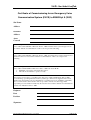
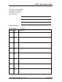
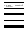
1
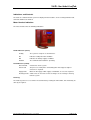
VoCALL
Fire Telephone &
Disabled Refuge System
User Manual & Log Book
Site Name
Address
Contractor
Commissioned
VoCALL User Guide & Log Book
Introduction
An EVCS is a fixed, secure, bi-directional, full duplex voice communication system to assist fire fighters
in an emergency in high rise buildings or large sites where Radio communication may not work, and
covers the operation of both fire telephones and disabled refuge systems.
The VoCALL Emergency Voice Communications System (EVCS) is designed to fully comply with
BS5839-Part 9:2003 (abb. Pt9) for use as a Fire Telephone system, Disabled Refuge Call system or as
a combined system when both Fire Telephones and Disabled Refuge Points are required.
Suitability
Fire telephone systems are recommended for all public buildings and multi story buildings over four
floors by BS5588.
Disabled Refuge systems are required in buildings where the public or disabled staff gain access to any
floor other than the ground floor using lifts.
Product Overview
A VoCALL EVCS comprises of three functional blocks, the master handset (VCM) the eight line
Exchanges (VCX-8) and outstations, (type A, type B or Jack points), with the quantities of these basic
units being adjusted to suit the application.
The VoCALL EVCS has been designed on a star and ring network topology; in the most cases this will
reduce the cable requirements from all ring-based systems and star systems. The topology consists of a
ring formed from either 2 off four core 1mm CSA cables (soft skin up to 500m per leg, MICC 200m per
leg) or 1 four pair 0.5mm CSA fire rated data cable. The exchange units and the control handsets sit on
this ring and communicate using a high speed balanced RS422 network, a bi-directional audio pair and
a power pair, which provides an ELV maintained supply to the control handsets.
Document DCC VOC7002-01 Rev 1 June 2006
Page 2 of 2
VoCALL User Guide & Log Book
Operation
All conversations on the VoCALL system are under the command of the control handset, if multiple
control handsets exist, the first operated one takes command of the system.
Pt9 envisages the majority of calls to be made by lifting the handset of an outstation (type A) or pressing
the call button (type B).
Receiving a call.
When a handset is lifted or the call button is pressed on the type B units, the phone on the control
point(s) will ring and the name of the calling extension will appear on the LCD display (all exchange lines
can be given a unique 16 character name to identify themselves such as “Floor 1 Riser E”).
The operator can then lift the handset and connect to the calling extension by pressing the # key. If
more than one line is calling, all calling lines show in the display, and may be scrolled through with the
navigate buttons, connected using the # key, or if already connected placed on hold using the # key a
second time.
If the control wishes to ring an outstation they may do this in one of two ways, either by entering the
number of the outstation using the keypad, or by scrolling through the names in the directory function
and pressing # over the line they want. To call all extensions select ALL from the directory and press #
or dial 0#.
Making a Call:
Lift the handset on the control phone, the either:
Dial the number of the line you require and press # to call, the line will connect automatically when the
remote handset is lifted or the call button is pressed.
Press the * key to scroll the display to the directory page. Once in the directory use the up and down
keys navigation to select the extension name you wish to call, and press # to call. The line will connect
when answered.
Ending or Holding a Call
Both call types can be ended by pressing the # key on the exchange line you no longer wish to call (if
the bell symbol is shown).
Pressing # while a remote outstation is speaking or is off hook will place the line on HOLD (the symbol
of an off hook phone is shown), you can talk to this line again by scrolling to it and pressing # again
Document DCC VOC7002-01 Rev 1 June 2006
Page 3 of 3
VoCALL User Guide & Log Book
Maintenance.
It is a requirement of BS5839pt9 that a maintenance agreement be in place for the EVCS, the
maintenance schedule should be as follows.
Weekly:
Lift a different handset on the system each week and make a call to the control,
repeat each week until all points are tested, record results in the site log.
Monthly:
Test one handset on each exchange by lifting the handset, followed by the master
calling the line, record results in the site log.
Quarterly:
Engineer Call to check system operation.
Yearly:
Engineer Call to check system operation and check Battery Health.
5 Yearly:
Engineer Call to check system operation and replace the batteries.
Document DCC VOC7002-01 Rev 1 June 2006
Page 4 of 4
VoCALL User Guide & Log Book
Indications and Controls
The faults on a VoCALL EVCS system are displayed in two locations, on the exchange with the fault,
and at the VCM master handset.
Mater Handset Indication.
The master handset has the following indications:-
Health Indicators (Green)
Healthy
The system is ready for use and fault free.
AC
Indicates healthy AC mains available.
DC
Indicates the battery supply is available.
Network
The communication network is operating.
Fault Indicators (Yellow)
General Fault
A fault exists on the system.
Panel Fault
The processor, main phone or watchdog timer have tripped, engineer
assistance is required.
Supply Fault
Either the AC supply or DC supply is unavailable, or a fuse has ruptured.
Exchange Fault A fault exists on one of the remote exchanges or an exchange is missing
from the system.
Fault Log
The Fault log can be accessed on the master handset by entering the PIN number, this should only be
done by an engineer.
Document DCC VOC7002-01 Rev 1 June 2006
Page 5 of 5
VoCALL User Guide & Log Book
Exchange Indications
The master handset has the following indications:-
LED
Fault
Supply
AC Ok
DC Ok
Meaning
This is a common fault LED and indicates that a current fault exists on this
exchange unit, this can be a line fault, processor failure, power supply
fault or network connection fault.
There is a fault with the power supply section of the exchange unit, this
could be lack of either AC or DC, rupture of a fuse or failure of the VRSLA
cell to hold charge
The mains AC voltage is present
The backup battery supply and charger are available to operate the
exchange in the event of a mains failure
Line LEDs
All 8-line indicators are identical in operation, and represent the exchange lines (numbered 1
to 8 on the exchange polycarbonate decal).
Each LED can have 3 states to indicate a fault as follows:LED State
Off
On Steady
Flashing
The line is healthy or has not been initialised so fault reporting is disabled
The line is short circuit or has an earth fault
The line is open circuit
A Fault LED on an exchange will illuminate the Exchange Fault LED on the master handsets, and place
a date time stamped entry into the master handset fault log.
Document DCC VOC7002-01 Rev 1 June 2006
Page 6 of 6
VoCALL User Guide & Log Book
Important Safety Information
This Equipment must only be installed and maintained by suitably skilled and competent
person.
This Equipment is defined as Class 1 in EN60950 (Low Voltage Directive) and must be
EARTHED.
CAUTION
INDOOR USE ONLY
WARNING
SHOCK HAZARDISOLATE BEFORE OPENING
WARNING
TO REDUCE THE RISK OF FIRE OR
ELECTRIC SHOCK, DO NOT EXPOSE THIS
UNIT TO RAIN OR MOISTURE
WARNING
WARNING
THIS UNIT MUST BE EARTHED
NO USER SERVICABLE PARTS
Each exchange unit requires a 3A spur, returning to a breaker clearly marked Fire Telephone
DO NOT TURN OFF. If the units are distributed around a site it is essential all units are on the
same mains phase, as they are classified TEN 230V, powering from different phases can
mean a 440V potential can be present in a unit during a major fault incident.
Anti-static handling guidelines
Make sure that electro-static handling precautions are taken immediately before handling
PCBs and other static sensitive components
Before handling any static-sensitive items, operators should get rid of any electrostatic charge
by touching a sound safety earth, such as a radiator. Always handle PCBs by their sides and
avoid touching any components. PCBs should be stored in a clean, dry place that is free from
vibration, dust and excessive heat.
Storing the PCBs in a suitable cardboard box will also guard them against mechanical
damage.
Document DCC VOC7002-01 Rev 1 June 2006
Page 7 of 7
VoCALL User Guide & Log Book
Batteries
The VoCALL Exchanges require a single 12V 3.2AH sealed lead acid batteries to provide backup power
in the event of mains failure as defined in BS5839pt9 for 24 hours standby and 30 minutes operation.
For 72hour standby and 1 hour operation a single 12V 7AH battery is required, the monitored charger in
the VoCALL Exchange is capable of charging and monitoring these batteries.
Safety Information:
Sealed Lead acid batteries contain sulphuric acid which can cause burns if
exposed to the skin, the low internal resistance of these batteries means large
currents will flow if they are accidentally short circuited, causing burns and a risk
of fire- exercise caution when handling batteries.
Power Up Procedure:
Always apply mains power before connecting batteries, do not commission
VoCALL on batteries, as the high inrush current required by the power supply
may rupture the battery fuse.
Always connect the Positive (Red +) terminal first.
Power Down Procedure
Disconnect the batteries before removing the mains power; always remove the
negative (Black – terminal) first.
The VoCALL EVCS is designed and manufactured in the UK by
Current Thinking Ltd,
Unit 91 Silver Briar
Enterprise Park East,
Sunderland,
SR5 2TQ.
www.current-thinking.com
[email protected]
Document DCC VOC7002-01 Rev 1 June 2006
Page 8 of 8
VoCALL User Guide & Log Book
Certificate of Commissioning for an Emergency Voice
Communication System (EVCS) to BS5839 pt 9 (2002)
Site Name
Address
Customer
Address
Areas
Covered
System Design:
In accordance with section 1 of BS 5839 : Part 9 : 2002 sub clause 6 the system design is has in
accordance with the recommendations of this code except for the following:
Installation:
In accordance with section 3 of BS 5839 : Part 9 : 2002, the wiring has been inspected and tested
and been found to be in accordance with the recommendations of this code except for the
following:
Commissioning:
In accordance with Section 4 of BS 5839 : Part 9 : 2002: sub clause 21.2C
1. Intelligible conversation is heard at all locations.
2. All controls and indicators operate correctly
The system is accepted in good working order and, in accordance with BS5839: Part 9, 2002,
record drawings, operating instructions and a system log book have been supplied and received.
Attention has been drawn to the recommendations concerning user's responsibilities, particularly
those concerned with routine attention and test procedures in section 5, and an appointed
responsible person should be nominated by the customer in accordance with the recommendations
of Section 6 of BS5839 : Part 9 : 2002.
Engineer
Date
Position
Signature:
Document DCC VOC7002-01 Rev 1 June 2006
Page 9 of 9
VoCALL User Guide & Log Book
Site Specific Information:
Equipment Locations
Master Handset # 1
Phone Locations
Exchange No. 1
Cable ID
Line
Location ________________________________________
Area Served
1
2
3
4
5
6
7
8
Document DCC VOC7002-01 Rev 1 June 2006
Page 10 of 10
VoCALL User Guide & Log Book
Exchange No. ____ Location _______________________________________
Cable ID
Line
Area Served
1
2
3
4
5
6
7
8
Copy this page as many times as required.
Document DCC VOC7002-01 Rev 1 June 2006
Page 11 of 11
VoCALL User Guide & Log Book
Log Book Page 1
Date
Event or Work Done
Engineer Company Signature
VoCALL System commissioned
Document DCC VOC7002-01 Rev 1 June 2006
Page 12 of 12
VoCALL User Guide & Log Book
Log Book Page __
Date
Event or Work Done
Engineer Company Signature
Copy this page as many times as required
Document DCC VOC7002-01 Rev 1 June 2006
Page 13 of 13