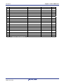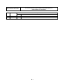
1
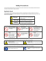
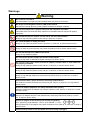
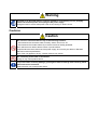
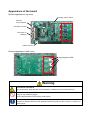
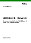
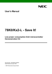
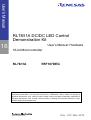
User’s Manual RL78/I1A DC/DC LED Control Demonstration Kit 16 User’s Manual: Hardware 16-bit Microcontroller RL78/I1A R5F107DEG All information contained in these materials, including products and product specifications, represents information on the product at the time of publication and is subject to change by Renesas Electronics Corp. without notice. Please review the latest information published by Renesas Electronics Corp. through various means, including the Renesas Electronics Corp. website (http://www.renesas.com). www.renesas.com Rev. 1.00 Mar. 2012 Preface Readers This manual is intended for users who want to understand the functions of the concerned microcontrollers. Purpose This manual presents the hardware manual for the concerned microcontrollers. Organization This system specification describes the following sections: Introduction How to use WriteEZ5 flash programming software System configuration Applilet EZ for HCD controller Board components Troubleshooting Getting started Schematics Hardware installation Bill of materials Software installation Module instances These microcontrollers may contain several instances of a dedicated module. In general the different instances of such modules are identified by the index “n”, where “n” counts from 0 to the number of instances minus one. Legend Symbols and notation are used as follows: Weight in data notation: Left is high order column, right is low order column Active low notation: xxx (pin or signal name is over-scored) or /xxx (slash before signal name) or _xxx Memory map address: High order at high stage and low order at low stage Note Additional remark or tip Caution Item deserving extra attention Numeric notation Binary: xxxx or xxxB Decimal: xxxx Hexadecimal xxxxH or 0x xxxx Numeric prefixes Representing powers of 2 (address space, memory capacity): K (kilo): 210 = 1024 M (mega): 220 = 1024² = 1,048,576 G (giga): 230 = 1024³ = 1,073,741,824 Register contents X, x = don’t care Diagrams Block diagrams do not necessarily show the exact wiring in hardware but the functional structure. Timing diagrams are for functional explanation purposes only, without any relevance to the real hardware implementation. Safety Precautions This document describes items to be observed to ensure the safe use of this evaluation board. Be sure to read this document before using the board. Symbols Used This document uses the following symbols for items to be observed to ensure the safe use of the unit. The symbols are followed by a brief explanation of the possible extent of problems which may occur if the items are not observed. Danger The risk is high if the warning is not observed, and the user may suffer death or serious injury. Warning The user may suffer death or serious injury if the warning is not observed. Caution Human injury or property damage may occur if the caution is not observed. The following symbols express behaviors that are prohibited in order to prevent injury or accident. General prohibition The action mentioned is prohibited. Do not touch Touching the specified location may cause injury. Do not disassemble Disassembly may cause a problem such as electric shock or product failure. Keep away from water Use near water poses the risk of electric shock or product failure if moisture were to contact the unit. Flammable Proximity to flame may cause the unit to catch fire. Do not touch with wet hands Touching with wet hands may cause electric shock or product failure. The following symbols are used for cautions to prevent product failure and accidents. General caution Unspecified general cautions Caution: Hot Human injury due to a high temperature The following symbols are used for instructions to prevent product failure and accidents. Action required of the user Instruction to unplug from AC power supply Warnings Warning Be careful to avoid burns. The temperature of this part of board increases when AC power is connected. Be careful of LED brightness and the LED On/Off interval. Simulations of strong light may cause symptoms linked to an epileptic condition. Do not use this board for a purpose other than the evaluation of an MCU. This board does not include the safety measures or anti-EMI measures required for lighting equipment. Do not heat the board or expose it to fire and do not short the terminals. Doing so may cause the product to fail, heat up, catch fire, or rupture. Do not disassemble or modify the board. Doing so may cause the product to fail, emit smoke, or catch fire, or result in electric shock. Do not touch with wet hands. Doing so while connected to power may cause the product to fail or result in electric shock. Do not look directly at the LEDs on this board. Doing so may weaken eyesight. Do not drop the board or subject the board to heavy impact. Doing so may break or damage the board, causing fire or electric shock. Do not turn on the power switch when the AC adapter, interface cable, or other cables are not properly connected. Doing so may cause the product to fail, heat up, or catch fire, or result in electric shock. Do not plug in or unplug a connector or cable with power applied to the board. Doing so may cause the product to fail, heat up, or catch fire, or result in electric shock. Do not move this board when the AC adapter or any cables are connected. Doing so may damage cables and cause the product to fail, heat up, or catch fire, or result in electric shock. Use this board with a spacer and on an electrically isolated bench. If a conductor contacts the board, the product may fail, heat up, or catch fire, or it may result in electric shock. Use an AC adapter adapted to the safety standard of each country. Using an inappropriate AC adapter may cause the product to fail, heat up, or catch fire, or result in electric shock. Use the specified AC adapter. Using an AC adapter other than that specified may cause the product to fail, heat up, or catch fire, or result in electric shock. Use an AC adapter of the following size and DC plug polarity. EIAJ Type2 Plug (outer diameter: 4.0 mm, inner diameter: 1.7 mm) Using another type of AC adapter may cause the product to fail, heat up, or catch fire, or result in electric shock. Confirm that the outlet is near this board and can be easily unplugged. Warning If smoke or an abnormal smell or sound is emitted or if overheating occurs, promptly switch off the board power and unplug the AC power supply. Using the board in such a state poses a risk of fire, burning or electric shock. Cautions Caution Do not use or store this board in any of the following locations. - Environments with excessive water, humidity, steam, dust, fume, etc. - Environments where static electricity or electrical noise is readily generated. Such influences can lead to electric shock or product failure. If liquid enters the board, disconnect the power supply, and consult your dealer or Renesas Electronics sales representative. Even if the unit appears to be dry, internal moisture may remain. Do not directly touch LEDs on this board. Doing so may cause product failure. To prevent static electricity damage, guard against static discharge when touching metal parts such as the connector. Static electricity can cause product failure. Appearance of the board Surface appearance (top view) Analog volume switch DC plug for AC adaptor Connector for DALI Connector for DMX512 USB connector Surface appearance (back view) High brightness LED Warning Be careful to avoid burns. Parts of the board, especially the area enclosed by a dotted line, become extremely hot. Do not look directly at LEDs on this board. Doing so may weaken eyesight. Use this board with the LED mounting surface back. Use a specified AC adapter. Using an AC adapter other than that specified causes the product to fail, heat up, or catch fire, or electric shock. Caution Do not touch directly LEDs on this board. Doing so may cause a product failure. For usage of this board, see the User’s Manual. The User’s Manual can be downloaded from the following webpage. URL: http://tool-support.renesas.com/eng/toolnews/download/exel/solution_lighting.html Table of Contents Chapter 1 1.1 1.2 1.3 Main features of RL78/I1A DC/DC LED Control Evaluation Board ..............1 System requirements......................................................................................2 Package contents............................................................................................2 Chapter 2 2.1 2.2 2.3 Normal Operation Mode ....................................................................................................4 On-Board Debug (OCD) Mode / Flash Programming Mode ..........................................5 E1 On-Chip Debug Mode ..................................................................................................5 Virtual UART Mode ............................................................................................................6 Configuration Switch SW1 .............................................................................6 Configuration Switch SW3 .............................................................................6 Reset Switch SW501 .......................................................................................7 External Power Supply CN1 ...........................................................................7 DALI Interface Connector CN2 .......................................................................7 DMX512 Interface Connector CN3 .................................................................7 InfraRed Detector U2 ......................................................................................7 E1 Emulator Connector J4 .............................................................................8 Programming Connector J3 ...........................................................................8 Mini-B USB Interface Connector CN501........................................................8 External Connectors J1 and J2 ......................................................................9 Low Power 32 KHz Resonator Y1 ................................................................11 RL78/I1A Memory Map ..................................................................................11 Chapter 4 4.1 Board Components .............................................................. 4 Configuration Switch SW2 .............................................................................4 3.1.1 3.1.2 3.1.3 3.1.4 3.2 3.3 3.4 3.5 3.6 3.7 3.8 3.9 3.10 3.11 3.12 3.13 3.14 System Configuration .......................................................... 3 RL78/I1A DC/DC LED Control Evaluation Board ..........................................3 Host Computer ................................................................................................3 Power Supply ..................................................................................................3 Chapter 3 3.1 Introduction .......................................................................... 1 Getting Started.................................................................... 12 Installed Contents .........................................................................................12 Chapter 5 Hardware Installation ......................................................... 13 Chapter 6 Software Installation .......................................................... 14 Chapter 7 How to Use WriteEZ5 Flash Programming Software ...... 15 Chapter 8 Applilet EZ for HCD Controller .......................................... 22 8.1 General Settings ...........................................................................................22 Index-1 8.2 8.3 8.4 8.5 8.6 8.7 Fix Dimmer Program .....................................................................................24 Variable Dimmer Program ............................................................................27 Analog Input Dimmer Program ....................................................................29 DMX512 Dimmer Program ............................................................................30 DALI Dimmer Program..................................................................................32 IR Remote Control Dimmer Program...........................................................34 Chapter 9 Troubleshooting ................................................................. 36 Chapter 10 Schematics ......................................................................... 38 Chapter 11 Bill of Materials ................................................................... 40 Index-2 R01UH0363EJ0100 Rev. 1.00 March 23, 2012 RL78/I1A RENESAS MCU Chapter 1 Introduction The RL78/I1A DC/DC LED Control Demonstration Kit comes with the RL78/I1A DC/DC LED Control Evaluation Board and a DVD containing all the appropriate software tools and documentation. The RL78/I1A DC/DC LED Control Evaluation Board is an evaluation board for the new Renesas RL78/I1A microcontroller. It supports On-Board debugging, flash programming, and is intended to demonstrate the RL78/I1A MCU’s special features dedicated to LED lighting system control. 1.1 Main features of RL78/I1A DC/DC LED Control Evaluation Board LED lighting system control demonstration capabilities RL78/I1A DC/DC LED Control Evaluation Board features circuits to perform constant current control of 3 LED channels (RGB LEDs) in order to demonstrate the special 16-bit Timers KBn (n = 0, 1, 2). o Buck topology o 350 mA maximum current per channel 4 types of dimming control interface supported o 3 ch. analog volume control interface (for standalone evaluation) o DALI protocol communication interface o DMX512 protocol communication interface o IR remote control interface Easy to use device demonstration capabilities RL78/I1A DC/DC LED Control Evaluation Board contains elements to easily demonstrate simple I/O-functions (i.e. LED output, I/O lines, UART serial interface) together with the other key functions such as Real Time Clock (RTC), ADC and Timers. Power supply via 5V DC connector RL78/I1A DC/DC LED Control Evaluation Board is powered via a 5V DC jack connector. This power supply is used to power the RL78/I1A as well as the LEDs. When On-Board debug function is used, the USB interface is used to power the µPD78F7030 78K0 USB microcontroller. On-Board debug function RL78/I1A DC/DC LED Control Evaluation Board supports an On-Board debug function by using the IAR C-SPY debugger, without the need of additional debug hardware. It allows flash programming and supports standard debug functions such as code execution, single stepping, software breakpoints, memory manipulation etc. (The E1 emulator can also be used for on-chip debugging) WriteEZ5, Flash programming software Windows based Flash programming software allows the user to select and download application programs to the RL78/I1A DC/DC LED Control Evaluation Board for evaluation purposes via USB. Applilet EZ for HCD Controller, Automated software generation tool Software tool used to generate full projects for different compilers. R01UH0363EJ0100 Rev. 1.00 March 23, 2012 1 RL78/I1A Chapter 1 Introduction Various input / output signals available, such as All I/O ports prepared to be connected to user hardware Virtual UART interface, via the µPD78F0730 78K0 8-bit microcontroller with on-board USB interface The IAR Embedded Workbench for RL78 and the IAR C-SPY debugger are included. These packages are restricted in such that maximum program code size is limited to 16 Kbytes. Full documentation is included for the Renesas software tools and the RL78/I1A device. 1.2 System requirements A PC supporting Windows XP, Windows Vista or 7 is required for the development tools installation. A Pentium processor with at least 1 GHz CPU performance, with at least 256 Mbytes of RAM, allowing you to fully utilize and take advantage of the product features. 350 Mbytes of free disk space and an additional 10 Mbytes of free disk space on the Windows system drive. HOST PC A web browser and Adobe Acrobat Reader to be able to access all the product documentation. Host interface USB interface that enables communication based on USB (Ver1.1 or later) 1.3 Package contents Please refer to the Package Contents List supplied with the product. If any part is missing or seems to be damaged, please contact the dealer from whom you received your RL78/I1A DC/DC LED Control Evaluation kit. R01UH0363EJ0100 Rev. 1.00 March 23, 2012 2 RL78/I1A Chapter 2 System Configuration Chapter 2 System Configuration The RL78/I1A DC/DC LED Control Evaluation Board system configuration is given in the diagram below: Figure 1: RL78/I1A DC/DC LED Control Evaluation Board System Configuration 2.1 RL78/I1A DC/DC LED Control Evaluation Board RL78/I1A DC/DC LED Control Evaluation Board is a demonstration board for evaluating the new Renesas RL78/I1A family of devices. The device used is the RL78/I1A (R5F107DEG). The board can be directly connected to the host system via a USB port. The host system may be used for On-Board debugging or Flash programming and to allow execution of the Demonstration program on the RL78/I1A device. As default, the RL78/I1A is using the 32 MHz internal high-speed oscillator, but the RL78/I1A DC/DC LED Control Evaluation Board is provided with a connection for an external 20 MHz oscillator (not fitted) if the user wishes to use a different clock frequency than that provided by the internal high speed oscillator. An external low power 32.768 KHz resonator is provided for the sub-clock. 2.2 Host Computer The USB host interface enables communication to the RL78/I1A DC/DC LED Control Evaluation Board. The µPD78F0730 78K0 8-bit microcontroller with onchip USB interface and the Renesas Electronics virtual UART driver allows application software to access the USB device in the same way as it would access a standard RS232 interface. The Renesas Electronics virtual UART driver appears to the windows system as an extra Com Port, in addition to any existing hardware Com Ports. 2.3 Power Supply RL78/I1A DC/DC LED Control Evaluation Board is powered by a 5V DC power supply and also by USB interface when the µPD78F0730 78K0 microcontroller is to be used for On-Board debugging, flash programming or virtual UART communication purpose. R01UH0363EJ0100 Rev. 1.00 March 23, 2012 3 RL78/I1A Chapter 3 Board Components Chapter 3 Board Components The RL78/I1A DC/DC LED Control Evaluation Board is equipped with a USB connector and with several connectors in order to be connected to host computers, E1 emulator, DALI or DMX master or any external target hardware. SW501 SW1 U2 VR1 VR2 VR3 CN1 SW2 CN2 J3 Y1 CN3 J4 CN501 J1 J2 Figure 2: RL78/I1A DC/DC LED Control Evaluation Board Components Some of the RL78/I1A DC/DC LED Control Evaluation Board components are free for user application hardware and software. Please read the User’s Manual of the RL78/I1A device carefully to get information about the electrical specification of the available I/O ports before you connect any external signal to the RL78/I1A DC/DC LED Control Evaluation Board. 3.1 Configuration Switch SW2 The switch SW2 controls the different operating modes of the RL78/I1A DC/DC LED Control Evaluation Board. 3.1.1 Normal Operation Mode The default operation of the board is set for Normal Operation mode. Switch SW2 should be set as shown in the table below: Bits Configuration 1* OFF 2* OFF 3 OFF 4 OFF 5 OFF 6 OFF 7 ON 8 ON Table 1: SW2, Normal Operation Mode * When DALI or DMX512 communication is to be used, bits 1 and 2 of switch SW2 should both be set to ON position. R01UH0363EJ0100 Rev. 1.00 March 23, 2012 4 RL78/I1A Chapter 3 Board Components 3.1.2 On-Board Debug (OCD) Mode / Flash Programming Mode The RL78/I1A DC/DC LED Control Evaluation Board supports on-board debug mode via the USB interface achieved by a dedicated monitor running on the RL78/I1A device. By using the IAR C-SPY debugger, flash programming and standard debug functions i.e. code execution, single stepping, software breakpoints, memory manipulation etc. are supported. Additionally the built-in Flash memory of the RL78/I1A device can be reprogrammed by using the WriteEZ5 Flash programming GUI. Configure switch SW2 as following to use the on-board debug or Flash programming mode: Bits 1* 2* 3 4 5 6 7 8 Configuration OFF OFF ON OFF ON OFF ON OFF Table 2: SW2, On-Board Debug / Flash Programming Mode * When DALI or DMX512 communication is to be used, bits 1 and 2 of switch SW2 should both be set to ON position. 3.1.3 E1 On-Chip Debug Mode The RL78/I1A DC/DC LED Control Evaluation Board also supports on-chip debug mode via the E1 emulator. When using the E1 emulator for on-chip debugging, the board can either be powered from the emulator or from the 5V DC power supply. Bits 1* 2* 3 4 5 6 7 8 Configuration OFF OFF OFF OFF OFF OFF ON ON Table 3: SW2, E1 On-Chip Debug Mode * When DALI or DMX512 communication is to be used, bits 1 and 2 of switch SW2 should both be set to ON position. R01UH0363EJ0100 Rev. 1.00 March 23, 2012 5 RL78/I1A Chapter 3 Board Components 3.1.4 Virtual UART Mode The RL78/I1A DC/DC LED Control Evaluation Board supports Virtual UART mode via the µPD78F0730 78K0 8-bit microcontroller. Switch SW2 should be set as shown in the table below: Bits 1* 2* 3 4 5 6 7 8 SW2, Virtual UART Mode Table 4: Configuration OFF OFF OFF ON OFF ON ON ON * When DALI or DMX512 communication is to be used, bits 1 and 2 of switch SW2 should both be set to ON position. 3.2 Configuration Switch SW1 The switch SW1 selects the lighting communication protocol to be used by the RL78/I1A DC/DC LED Control Evaluation Board. When using DALI or DMX512 communication, please don’t forget to set bits 1 and 2 of switch SW2 to ON position. Configuration 1-2 & 4-5 3-2 & 6-5 Function DALI DMX512 Table 5: SW1, Lighting Communication Protocol Selection 3.3 Configuration Switch SW3 The switch SW3 selects the IR remote control channel. Two different channels can be selected on the RL78/I1A DC/DC LED Control Evaluation Board, CH1 corresponds to a 0x5AA5 data code, and CH2 to a 0xDA25 data code. Configuration CH1 CH2 Function Custom code: 0x0000+Data code: 0x5AA5 Custom code: 0x0000+Data code: 0xDA25 Table 6: SW3, IR Remote Control Channel Selection R01UH0363EJ0100 Rev. 1.00 March 23, 2012 6 RL78/I1A Chapter 3 Board Components 3.4 Reset Switch SW501 The switch SW501 is the reset switch of the RL78/I1A DC/DC LED Control Evaluation Board. It can be used to reset operation during on-board debugging or during normal operation mode. 3.5 External Power Supply CN1 External power is supplied by connecting a regulated 5V DC to the jack connector CN1. The operation of the board is as follows: - External supply only (The board can only be operated as stand alone only, no USB power connection). Or - External supply and USB power (This configuration should be used when the user intends to use On-Board debugging, flash programming or virtual UART communication via the µPD78F0730 78K0 8-bit microcontroller). 3.6 DALI Interface Connector CN2 CN2 is the connector for DALI interface. CN2 is a 2-way connector to enable communication with a DALI master via the DALI communication protocol. 3.7 DMX512 Interface Connector CN3 CN3 is the connector for DMX512 interface. CN3 is a 3-way connector to enable communication with a DMX512 master via the DMX512 communication protocol. 3.8 InfraRed Detector U2 InfraRed (IR) detector U2 can be used to enable IR communication between a controller device and the RL78/I1A. The controller device can send commands to the RL78/I1A microcontroller using the IR communication protocol. R01UH0363EJ0100 Rev. 1.00 March 23, 2012 7 RL78/I1A Chapter 3 Board Components 3.9 E1 Emulator Connector J4 Connector J4 (not fitted) is provided to allow debugging and programming of the RL78/I1A microcontroller using the E1 OCD emulator. This function allows the user to be able to debug an application and make use of the UART0 serial interface that can use the Renesas Virtual UART to interface to the PC. For this function a 14way (2 x 7) standard pitch connector needs to be mounted and connected as shown below. Figure 3: E1 Emulator Connection 3.10 Programming Connector J3 Connector J3 is provided for production programming of the µPD78F0730 78K0 8bit microcontroller during manufacturing. The 78K0/USB device should not be reprogrammed. 3.11 Mini-B USB Interface Connector CN501 The mini-B USB connector allows connecting the IDE or the WriteEZ5 Flash programming software to the RL78/I1A DC/DC LED Control Evaluation Board in order to debug or program application software to the RL78/I1A device. The power supply for the 78K0/USB device is also provided by this connector. Additionally connector CN501 connects the UART0 serial interface of the RL78/I1A device to the host system. Figure 4: Connector CN501, Mini USB B Type Connector Pin Configuration R01UH0363EJ0100 Rev. 1.00 March 23, 2012 8 RL78/I1A Chapter 3 Board Components USB Connector CN501 1 2 3 4 5 Signal Name V BUS DD+ NC GND Table 7: Pin Configuration of mini-B USB Connector CN501 For connection with the host machine, the RL78/I1A DC/DC LED Control Evaluation Board can be plugged directly into an available USB port. 3.12 External Connectors J1 and J2 J1 to J2 are connectors for external user hardware. Standard 0.1’ pitch, 10-way double row, straight headers are mounted to bring all I/Os for usage. Please read the User’s Manual of the RL78/I1A device carefully to get information about the electrical specification of the available I/O ports. Figure 5: External Connectors J1 and J2 R01UH0363EJ0100 Rev. 1.00 March 23, 2012 9 RL78/I1A J1 1 2 3 4 5 6 7 8 9 10 11 12 13 14 15 16 17 18 19 20 Chapter 3 Board Components Signal Name P20 P03 P02 P120 P40 RESET P124 P123 P137 P122 P121 REGC VSS VDD P31 P77 P76 P61 P75 - RL78/I1A Pin Name P20/ANI0/AVREFP P03/RXD1/CMP5P/ANI16 P02/TXD1/ANI17 P120/ANI19 P40/TOOL0 RESET P124/XT2/EXCLKS P123/XT1 P137/INTP0 P122/X2/EXCLK P121/X1 REGC VSS VDD P31/TI03/TO03/INTP4 P77/INTP11 P76/INTP10 P61/SDAA0 P75/INTP9 - Comment Connected to VDD No connection Table 8: Connector J1 J2 1 2 3 4 5 6 7 8 9 Signal name P21 P22 P24 P25 P26 P27 P147 P10 P11 10 11 12 13 14 15 16 17 18 19 20 P12 P200 P201 P202 P203 P204 P205 P206 P30 P05 - RL78/G13 Pin Name Comment P21/ANI1/AVREFM Connected to VSS P22/ANI2/CMP0P P24/ANI4/CMP1P P25/ANI5/CMP2P P26/ANI6/CMP3P P27/ANI7/CMP4P P147/CMPCOM/ANI18 P10/SO00//TXD0/TKCO00/INTP20/SCLA0/(DALITxD4) P11/SI00//RXD0/TKCO01/INTP21/SDAA0/(TI07)/(DALIRxD4)/ (TxRx4) P12/_SCK00/(TKCO03) P200/TKBO00/INTP22 P201/TKBO01 P202/TKBO10/(INTP21) P203/TKBO11/TKCO02/(INTP20) P204/TKBO20/TKCO03 P205/TKBO21/TKCO04/DALITxD4 P206/TKCO05/DALIRxD4/TXRx4/INTP23 P30/INTP3/RTC1HZ P05/TI05/TO05 No connection Table 9: Connector J2 R01UH0363EJ0100 Rev. 1.00 March 23, 2012 10 RL78/I1A Chapter 3 Board Components 3.13 Low Power 32 KHz Resonator Y1 The RL78/I1A DC/DC LED Control Evaluation Board is fitted with an external 32 KHz resonator (Y1) characterized specifically for the RL78 devices supplied by Seiko Instruments Inc. This is a specially designed low power resonator designed to support the very low power consumption of the RL78 family. 3.14 RL78/I1A Memory Map The RL78/I1A memory layout is shown in the table below. 0xFFFFF 0xFFF00 0xFFEFF Address area 0xFFF00 0xFFEFF 0xF2000 0xF1FFF 0xF1000 0x0F0FFF SFR Area 256 bytes Internal RAM 4KB Free for user application software Mirror 51.75 KB Data flash memory 4 KB Access prohibited area 0xF0800 0x0F07FF 0xF0000 0xEFFFF 2nd SFR 2 KB Free for user application software Access prohibited area 0x10000 0x0FFFF 64 KB code flash memory 0x00000 Free for user application software Table 10: RL78/I1A Memory Map R01UH0363EJ0100 Rev. 1.00 March 23, 2012 11 RL78/I1A Chapter 4 Getting Started Chapter 4 Getting Started The default setting of the RL78/I1A DC/DC LED Control Evaluation Board is set for demonstration of LED constant current control and dimming control using onboard variable resistors. The RL78/I1A DC/DC LED Control Evaluation Board comes already flash programmed with the LED control sample program. The Quick Start Guide supplied in printed form and on the CD as a PDF file will take the user through the software installation procedure. 4.1 Installed Contents The CD has a file called versions.txt in the root, this confirms the exact software components and versions installed. R01UH0363EJ0100 Rev. 1.00 March 23, 2012 12 RL78/I1A Chapter 5 Hardware Installation Chapter 5 Hardware Installation After unpacking the RL78/I1A DC/DC LED Control Evaluation Board, connect the supplied USB cable to the board. This driver must be installed before the user can use the debugger, to do this, just install the software supplied; please refer to the accompanying Quick Start guide (D011299-11 R01UH0363EJ0100 Rev. 1.00 March 23, 2012 13 RL78/I1A Chapter 6 Software Installation Chapter 6 Software Installation Please refer to the accompanying Quick Start guide (D011299-11) also found on the Software CD for instructions on how to install the software for this product. R01UH0363EJ0100 Rev. 1.00 March 23, 2012 14 RL78/I1A Chapter 7 How to Use WriteEZ5 Flash Programming Software Chapter 7 How to Use WriteEZ5 Flash Programming Software This chapter explains the basic operations of the WriteEZ5 GUI for programming the RL78/I1A DC/DC LED Control Evaluation Board. This chapter covers how to start the system, execute the EPV command (Erase, Program, Verify), and program the target RL78/I1A device. The conditions of the series of operations described in this chapter are as follows: Hardware Board: Configuration of CPU: RL78/I1A DC/DC LED Control Target Device: Evaluation Board Voltage level: Software Parameter file: Configuration of Clock setting: WriteEZ5 GUI Port: RL78/I1A DC/DC LED Control Evaluation Board RL78/I1A R5F107DE 5V R5F107DE.pr5 Internal-OSC COMxx (115200bps) Operation mode: Chip Write HEX file: *.hex Option Setting: Blank check before Erase <1> Installing the Running the Software CD installation supplied with this product will automatically WriteEZ5 GUI deploy the correct software. <2> Installing the Running the Software CD installation supplied with this product will automatically driver deploy the correct software. <3> Installing the Running the Software CD installation supplied with this product will automatically parameter files deploy the correct software. <4> Setting and Set the RL78/I1A DC/DC LED Control Evaluation Board by configuring switch connecting SW2 as following: Bits 1 2 3 4 5 6 7 8 Configuration OFF OFF ON OFF ON OFF ON OFF Table 11: SW2, Configuration for Flash Programming Mode R01UH0363EJ0100 Rev. 1.00 March 23, 2012 15 RL78/I1A Chapter 7 How to Use WriteEZ5 Flash Programming Software Figure 6: SW2 for Mode Configuration Connect the RL78/I1A DC/DC LED Control Evaluation Board with the host machine. <5> Starting Start the WriteEZ5 GUI from the start menu: [Start] [All Programs] [Renesas Electronics Tools] [WriteEZ5] Or use the shortcut icon on your Desktop. Figure 7: WriteEZ5 Start-up Screen <6> Setting the (6.1) Select [Device] [Setup] from the menu bar or click on the [Setup] icon. programming The “Standard” tab of the “Device Setup” dialog box is opened: environment R01UH0363EJ0100 Rev. 1.00 March 23, 2012 16 RL78/I1A Chapter 7 How to Use WriteEZ5 Flash Programming Software Figure 8: Standard Device Setup Dialog Box (6.2) Click on PRM File Read to open the parameter file selection window. Select the parameter file “R5F107DE.pr5”, and then click Open . Figure 9: Parameter File Selection (6.3) From the “Port” list box, select the communication port that matches the host machine being used. Select the communication speed of the host connection. R01UH0363EJ0100 Rev. 1.00 March 23, 2012 17 RL78/I1A Chapter 7 How to Use WriteEZ5 Flash Programming Software Figure 10: Port Selection Remark Selectable ports can be checked using Device Manager. The user must have installed the software first. (6.5) Switch to the “Advance” dialog box: In “Command Options”, check “Blank check before Erase”. In “Security flag settings”, all the different options should remain unchecked. R01UH0363EJ0100 Rev. 1.00 March 23, 2012 18 RL78/I1A Chapter 7 How to Use WriteEZ5 Flash Programming Software Figure 11: Advance Device Setup Dialog Box (6.6) Click on the button OK . The GUI software sets the parameters. When the settings have bee completed, the following screen is displayed: Figure 12: Completion of Parameter Settings R01UH0363EJ0100 Rev. 1.00 March 23, 2012 19 RL78/I1A Chapter 7 How to Use WriteEZ5 Flash Programming Software <7> Selecting a user (7.1) Select [File] [Load] from the menu bar or click on the [Load] icon. program (7.2) Select a program file to be written to the target device, then click on the button Open . Figure 13: Completion of HEX File Download <8> Auto procedure Select [Device] [Autoprocedure(EPV)] form the menu bar or click on the (EPV) command [Autoprocedure] icon. execution When the [Autoprocedure(EPV)] command is executed, Blank Check Erase Program and Flash Internal Verify are executed sequentially for the RL78/I1A device. Figure 14: Completion of EPV Command R01UH0363EJ0100 Rev. 1.00 March 23, 2012 20 RL78/I1A Chapter 7 How to Use WriteEZ5 Flash Programming Software <9> Terminating the Select [File] [Quit] to terminate the GUI software. All settings executed are GUI saved, so that those settings can be reused when the WriteEZ5 GUI is restarted. <10> Execute Set the RL78/I1A DC/DC LED Control Evaluation Board to the normal operation application mode by applying the following settings. Bits Configuration 1 OFF 2 OFF 3 OFF 4 OFF 5 OFF 6 OFF 7 ON 8 ON Table 12: SW2, Configuration for Normal Operation Mode <11> Restarting the When the WriteEZ5 GUI is restarted, the latest settings should be applied. GUI R01UH0363EJ0100 Rev. 1.00 March 23, 2012 21 RL78/I1A Chapter 8 Applilet EZ for HCD Controller Chapter 8 Applilet EZ for HCD Controller Applilet EZ for HCD Controller is a software tool used to automatically generate software code for the RL78/I1A microcontroller (and also for the 78K0/Ix2), which is used to control the LED current. Software can be easily generated by specifying the setting and operation of the RL78/I1A on the GUI. The generated software can be directly written into the flash memory of the RL78/I1A microcontroller via a USB cable and the operation can be performed and checked by using the RL78/I1A DC/DC LED Control Evaluation Board. By using Applilet EZ for HCD Controller, a digital RL78/I1A-based lighting system can be designed without requiring a detailed knowledge of complex programming languages. Furthermore, microcontroller software development, which can usually take a certain amount of time, and operation evaluation can be significantly reduced. For further information please refer to the “Applilet EZ for HCD Controller User’s Manual” which can be found on the Renesas website. 8.1 General Settings This section will go through the different Applilet EZ for HCD Controller’s general settings. <1> Open Applilet EZ for HCD Controller. Figure 15: Applilet EZ for HCD Controller Main Window R01UH0363EJ0100 Rev. 1.00 March 23, 2012 22 RL78/I1A Chapter 8 Applilet EZ for HCD Controller <2> Under the Project menu all of the MCU settings will be listed for configuration, select CPU or simply press the “New” button. Figure 16: Applilet EZ for HCD Controller New Project <3> In the CPU settings, select Target to EZ-0012 board. Figure 17: Applilet EZ for HCD Controller CPU Settings <4> The Applilet EZ tool is able to generate code and projects for different compilers, one of them is the IAR compiler. Select it by clicking on the Setting menu, then Select Compiler and choose the IAR compiler. Figure 18: Applilet EZ for HCD Controller Compiler Selection R01UH0363EJ0100 Rev. 1.00 March 23, 2012 23 RL78/I1A Chapter 8 Applilet EZ for HCD Controller Note Make sure that you have installed the selected compiler correctly to your host PC before building the project. <5> It is also possible to configure the output project folders by clicking on the Setting menu and then selecting Project Folder. These locations will specify the output paths of the generated files. Enter in your desired destination but please keep in mind that Applilet EZ will then create subdirectories under this folder for each Applilet EZ project. Click OK. Figure 19: Applilet EZ for HCD Controller Project Folder 8.2 Fix Dimmer Program This program sets a fixed duty value for each of the 3 LED channels. Make sure that all settings explained previously are still correctly set before proceeding with the following steps. <1> Make sure “Fix Duty” is still selected as the dimmer program. <2> Input “128” to all the channels so they are not too bright. Figure 20: Applilet EZ for HCD Controller Fix Duty Settings <3> We can then save the new Applilet EZ project (.hcd file). Select the File menu, then click on Save As… or simply click on the “Save” button, and input “fix.hcd” for example. To finish click Save. R01UH0363EJ0100 Rev. 1.00 March 23, 2012 24 RL78/I1A Chapter 8 Applilet EZ for HCD Controller Figure 21: Applilet EZ for HCD Controller Save As Window <4> Please make sure to set the SW2 dip switch to the flash programming mode. Then plug the power cable to the RL78/I1A DC/DC LED Control Evaluation Board, and plug the USB connector. Click the “All P.“ button. Figure 22: Applilet EZ for HCD Controller All Program Button <5> You will be informed about the progress of the compilation. Figure 23: Applilet EZ for HCD Controller Compilation Progress R01UH0363EJ0100 Rev. 1.00 March 23, 2012 25 RL78/I1A Chapter 8 Applilet EZ for HCD Controller <6> Next click OK when prompt to start flash programming. Figure 24: Applilet EZ for HCD Controller Start Flash Programming <7> During the flash programming procedure you will be informed about the actual status of the programming. Figure 25: Applilet EZ for HCD Controller Flash Programming Status <8> Click CLOSE to exit the “Build” window. Remove the USB cable and the power supply cable, and change the SW2 dip switch positions to the normal operation mode. Plug the power supply cable to the board connector again and you should see the LEDs light up according to the duty values set earlier. LED channel 1 = Red LED channel 2 = Green LED channel 3 = Blue R01UH0363EJ0100 Rev. 1.00 March 23, 2012 26 RL78/I1A Chapter 8 Applilet EZ for HCD Controller 8.3 Variable Dimmer Program This program sets the duty value for each channel according to a drawing pattern data. <1> Make sure that you have set all the settings as explained in the 8.1 General Settings section. <2> Save the new Applilet EZ project (.hcd file). Select the File menu, then click on Save As… or simply click on the “Save” button, and input “variable.hcd” for example. To finish click Save. Figure 26: Applilet EZ for HCD Controller Save As Window <3> We now have a new Applilet EZ project file and we will change the dimmer program to Variable. Figure 27: Applilet EZ for HCD Controller Dimmer Program Selection (Variable) <4> Click on the “Edit” button under “Variable” and the “Dimmer Programming” window will open. Enable the “Cyclic” check box. Click the “Ch.1“ button to select this channel for modification. Select the line mode as shown below. This will allow you to draw the PWM duty cycle versus time by using your mouse pointer. R01UH0363EJ0100 Rev. 1.00 March 23, 2012 27 RL78/I1A Chapter 8 Applilet EZ for HCD Controller Figure 28: Applilet EZ for HCD Controller Dimmer Programming (Variable) <5> Draw something close to the sinusoidal wave below and then click OK. Figure 29: Applilet EZ for HCD Controller Wave Editor (1 channel) R01UH0363EJ0100 Rev. 1.00 March 23, 2012 28 RL78/I1A Chapter 8 Applilet EZ for HCD Controller <6> Repeat the same process for the two other channels. Then click on the OK button to exit the variable dimmer control window. Figure 30: Applilet EZ for HCD Controller Wave Editor (3 channels) <7> Make sure that SW2 dip switch of the RL78/I1A DC/DC LED Control Evaluation Board is in flash programming mode, and that the USB and power supply cables are connected correctly. Click the “Save” button and then the “All P.” button. After downloading the application, please disconnect the USB and power supply cables and set the board to the normal operation mode. <8> Plug again the DC 5V power supply, and you should now see the on-board LEDs running the variable dimming application based on the above wave form. 8.4 Analog Input Dimmer Program This program sets the duty value for each channel according to the on-board variable resistors values read from the A/D converter. <1> Make sure that you have set all the settings as explained in the 8.1 General Settings section. R01UH0363EJ0100 Rev. 1.00 March 23, 2012 29 RL78/I1A Chapter 8 Applilet EZ for HCD Controller <2> Save the new Applilet EZ project (.hcd file). Select the File menu, then click on Save As… or simply click on the “Save” button, and input “analog.hcd” for example. To finish click Save. <3> We now have a new Applilet EZ project file and we will change the dimmer program to Analog Input. Figure 31: Applilet EZ for HCD Controller Dimmer Program Selection (Analog) <4> Make sure that SW2 dip switch of the RL78/I1A DC/DC LED Control Evaluation Board is in flash programming mode, and that the USB and power supply cables are connected correctly. Click the “Save” button and then the “All P.” button. After downloading the application, please disconnect the USB and power supply cables and set the board to the normal operation mode. <5> Plug again the DC 5V power supply, and you should now see the on-board LED brightness changing according to the actions applied to the variable resistors (VR1, VR2 and VR3). 8.5 DMX512 Dimmer Program This sample shows how to set up Applilet EZ to program the DM512 stack into the R5F107DEG assembled to the RL78/I1A DC/DC LED Control Evaluation Board. <1> Make sure that you have set all the settings as explained in the 8.1 General Settings section. <2> Save the new Applilet EZ project (.hcd file). Select the File menu, then click on Save As… or simply click on the “Save” button, and input “dmx512.hcd” for example. To finish click Save. <3> We now have a new Applilet EZ project file and we will change the dimmer program to DMX512. Figure 32: Applilet EZ for HCD Controller Dimmer Program Selection (DMX512) R01UH0363EJ0100 Rev. 1.00 March 23, 2012 30 RL78/I1A Chapter 8 Applilet EZ for HCD Controller <4> Open the “DMX512 Property” dialogue box by selecting the Project menu and clicking on DMX512… or simply by clicking on the “Setting” button. Check that the settings are as shown below. Figure 33: Applilet EZ for HCD Controller DMX512 Property Dialogue Box <5> Make sure that SW2 dip switch of the RL78/I1A DC/DC LED Control Evaluation Board is in flash programming mode, and that the USB and power supply cables are connected correctly. Click the “Save” button and then the “All P.” button. After downloading the application, please disconnect the USB and power supply cables and set the board to the normal operation mode. You should now be able to control the LEDs on the RL78/I1A DC/DC LED Control Evaluation Board via the DMX512 protocol by connecting a DMX512 master device. For example, Renesas Electronics offers the Lighting Communication Master Evaluation Board (EZ-0008). This board can be used as a communication master device supporting DMX512, DALI and IR communications. <6> The RL78/I1A DC/DC LED Control Evaluation Board can be controlled by this Lighting Communication Master Evaluation Board together with a GUI running on the host PC. There is a GUI for DMX512 control and a GUI for DALI control, both GUIs can be downloaded from the Renesas Electronics website. Figure 34: System Configuration for DMX512 Control R01UH0363EJ0100 Rev. 1.00 March 23, 2012 31 RL78/I1A Chapter 8 Applilet EZ for HCD Controller <7> On the Lighting Communication Master Evaluation Board, please confirm that SW4 is set to “RUN“ and SW3 is set to “DMX”. <8> Connect the Lighting Communication Master Evaluation Board (EZ-0008), via the DMX connector J1, with the RL78/I1A DC/DC LED Control Evaluation Board (acting as a DMX512 slave board), via the DMX connector CN3, using the three wires provided. <9> Connect the Lighting Communication Master Evaluation Board to the host PC using a USB cable. <10> Plug the DC 5V power supply cable to the RL78/I1A DC/DC LED Control Evaluation Board via connector CN1. <11> Send DMX512 commands to the RL78/I1A DC/DC LED Control Evaluation Board using the DMX512 Master Controller GUI. Note To find details about the DMX512 Master Controller GUI, please refer to the corresponding User’s Manual (U19596EJ1V0UM00) that can be downloaded from the Renesas Electronics website. 8.6 DALI Dimmer Program This sample shows how to set up Applilet EZ to program the DALI (Digital Addressable Lighting Interface) stack into the R5F107DEG assembled to the RL78/I1A DC/DC LED Control Evaluation Board. <1> Make sure that you have set all the settings as explained in the 8.1 General Settings section. <2> Save the new Applilet EZ project (.hcd file). Select the File menu, then click on Save As… or simply click on the “Save” button, and input “dali.hcd” for example. To finish click Save. <3> We now have a new Applilet EZ project file and we will change the dimmer program to DALI. Figure 35: Applilet EZ for HCD Controller Dimmer Program Selection (DALI) R01UH0363EJ0100 Rev. 1.00 March 23, 2012 32 RL78/I1A Chapter 8 Applilet EZ for HCD Controller <4> Open the “DALI Property” dialogue box by selecting the Project menu and clicking on DALI… or simply by clicking on the “Setting” button. Choose the appropriate settings for your evaluation. Figure 36: Applilet EZ for HCD Controller DALI Property Dialogue Box <5> Make sure that SW2 dip switch of the RL78/I1A DC/DC LED Control Evaluation Board is in flash programming mode, and that the USB and power supply cables are connected correctly. Click the “Save” button and then the “All P.” button. After downloading the application, please disconnect the USB and power supply cables and set the board to the normal operation mode. You should now be able to control the LEDs on the RL78/I1A DC/DC LED Control Evaluation Board via the DALI protocol by connecting a DALI master device. For example, Renesas Electronics offers the Lighting Communication Master Evaluation Board (EZ-0008). This board can be used as a communication master device supporting DMX512, DALI and IR communications. <6> The RL78/I1A DC/DC LED Control Evaluation Board can be controlled by this Lighting Communication Master Evaluation Board together with a GUI running on the host PC. There is a GUI for DMX512 control and a GUI for DALI control, both GUIs can be downloaded from the Renesas Electronics website. Figure 37: System Configuration for DALI Control R01UH0363EJ0100 Rev. 1.00 March 23, 2012 33 RL78/I1A Chapter 8 Applilet EZ for HCD Controller <7> On the Lighting Communication Master Evaluation Board, please confirm that SW4 is set to “RUN“. <8> Connect the Lighting Communication Master Evaluation Board (EZ-0008), via the DALI connector J4, with the RL78/I1A DC/DC LED Control Evaluation Board (acting as a DALI slave board), via the DALI connector CN2, using the two wires provided. <9> Connect the Lighting Communication Master Evaluation Board to the host PC using a USB cable. <10> Plug the DC 5V power supply cable to the RL78/I1A DC/DC LED Control Evaluation Board via connector CN1. <11> Send DALI commands to the RL78/I1A DC/DC LED Control Evaluation Board using the DALI Master Controller GUI. Note To find details about the DALI Master Controller GUI, please refer to the corresponding User’s Manual (U19607EJ1V1UM00) that can be downloaded from the Renesas Electronics website. 8.7 IR Remote Control Dimmer Program This sample shows how to set up Applilet EZ to program the IR remote control dimming program into the R5F107DEG assembled to the RL78/I1A DC/DC LED Control Evaluation Board. <1> Make sure that you have set all the settings as explained in the 8.1 General Settings section. <2> Save the new Applilet EZ project (.hcd file). Select the File menu, then click on Save As… or simply click on the “Save” button, and input “ir.hcd” for example. To finish click Save. <3> We now have a new Applilet EZ project file and we will change the dimmer program to IR Remote Control. The “Custom Code” and “Data Code” can be customized according to the user’s needs. Figure 38: Applilet EZ for HCD Controller Dimmer Program Selection (IR) R01UH0363EJ0100 Rev. 1.00 March 23, 2012 34 RL78/I1A Chapter 8 Applilet EZ for HCD Controller <4> Make sure that SW2 dip switch of the RL78/I1A DC/DC LED Control Evaluation Board is in flash programming mode, and that the USB and power supply cables are connected correctly. Click the “Save” button and then the “All P.” button. After downloading the application, please disconnect the USB and power supply cables and set the board to the normal operation mode. <5> Plug again the DC 5V power supply, and you should now be able to control the LEDs on the RL78/I1A DC/DC LED Control Evaluation Board via the IR remote control protocol by using an IR transmitter device. For example, Renesas Electronics offers the Lighting Communication Master Evaluation Board (EZ0008). This board can be used as a communication master device supporting DMX512, DALI and IR communications. Figure 39: System Configuration for IR Remote Control <6> On the Lighting Communication Master Evaluation Board, please confirm that SW4 is set to “RUN“ and SW1 to the expected channel (the channel should be the same as the one set in Applilet EZ for HCD). The output code is based on NEC IR remote control protocol: CH1: Send custom code 0x0000+data code 0x5AA5 CH2: Send custom code 0x0000+data code 0xDA25 <7> Place the IR transmitter (LED1) of the Lighting Communication Master Evaluation Board in the line-of-sight of the IR receiver (U2) of the RL78/I1A DC/DC LED Control Evaluation Board. <8> Connect the Lighting Communication Master Evaluation Board to the host PC using a USB cable. <9> Plug the DC 5V power supply cable to the RL78/I1A DC/DC LED Control Evaluation Board via connector CN1. <10> Press switch SW2 of the Lighting Communication Master Evaluation Board to send IR signals to the RL78/I1A DC/DC LED Control Evaluation Board. R01UH0363EJ0100 Rev. 1.00 March 23, 2012 35 RL78/I1A Chapter 9 Troubleshooting Chapter 9 Troubleshooting In driver installation, recognition based on Plug and Play is disabled. Cause: The USB connector may not be inserted normally into the USB port of the personal computer. Action: Check that the USB connector is inserted fully into the USB port of the personal computer. Alternatively, disconnect the USB connector, and then insert the USB connector again after a while. The driver file cannot be found at a specific location Cause: The WriteEZ5 programming software may not be installed correctly. Action: Install the WriteEZ5 software again by referring to Chapter 6 Software Installation. In checking by Device Manager, "USB Serial Port" or "USB High Speed Serial Converter" is not displayed. Alternatively, the "!" or "" is prefixed Cause: The USB connector may not be inserted normally into the USB port of the personal computer. Action: Check that the USB connector is inserted fully into the USB port of the personal computer. Alternatively, disconnect the USB connector from the USB port, then insert the USB connector again after a while. Cause: The driver may not be installed correctly. Action: <1> When this product is connected to the personal computer, right-click the driver marked with "!" or "". Click Erase when displayed. <2> On Device Manager, execute [Hardware Modification Scan]. <3> Install the driver again with Plug and Play. Cause: The device may not be recognized (in the case of connection with the USB hub). R01UH0363EJ0100 Rev. 1.00 March 23, 2012 36 RL78/I1A Chapter 9 Troubleshooting Action: Try the following: Disconnect the USB connector, then insert the USB connector again. Connect the USB connector to another port of the USB hub. If the same symptom occurs, do not use the USB hub, but directly connect the connector to the USB port of the personal computer. When this product is connected with a personal computer, the "Add New Hardware Wizard" screen is displayed Cause: If the USB connector of this product is not inserted into the USB port used at the installation time but into another USB port, this product may be recognized as a new hardware item. Action: Install the driver by referring to Chapter 6 Software Installation. Communication with the RL78/I1A DC/DC LED Control Evaluation Board is disabled Cause: The driver may not be installed correctly. Action: Check if the USB driver is installed correctly by referring to Chapter 6 Software Installation. Cause: The COM port selected via the “Port list box” within device setup menu of WriteEZ5 may not be set correctly. Action: Set the port checked using Device Manager. Cause: The RL78/I1A DC/DC LED Control Evaluation Board is operating in Virtual UART mode. Action: Set the board to the On-Board Debugging / Flash Programming mode. Cause: The PRM file selected in [Device Setup] may be incorrect. Action: Use the corresponding PRM file that matches the target device. For information about the PRM file, refer to Chapter 7 How to Use WriteEZ5 Flash Programming Software. R01UH0363EJ0100 Rev. 1.00 March 23, 2012 37 RL78/I1A Chapter 10 Schematics Chapter 10 Schematics Figure 40: RL78/I1A DC/DC LED Control Evaluation Board Schematic R01UH0363EJ0100 Rev. 1.00 March 23, 2012 38 RL78/I1A Chapter 10 Schematics Figure 41: Top and Bottom Silkscreen R01UH0363EJ0100 Rev. 1.00 March 23, 2012 39 RL78/I1A Chapter 11 Bill of Materials Chapter 11 Bill of Materials Item Reference Parts name Rating Type 1 C1, C2 Laminated ceramic capacitor 3.7 pF @ 50 V 1005 2 C3 Laminated ceramic capacitor 0.47 F @ 25 V 1608 3 C4, C5 Laminated ceramic capacitor 0.1 F @ 50 V 1608 4 C101-C103, C201-C203, C301-C303 Laminated ceramic capacitor 10 F @ 16 V 2012 5 C104, C105, C204, C205, C304, C305, C401, C403, C404, C501, C503, C509C511 Laminated ceramic capacitor 0.1 F @ 50 V 1608 6 C402, C502, C512 Electrolytic capacitor 22 F @ 50 V DIP 7 C504 Laminated ceramic capacitor 0.01 F @ 50 V 1608 8 C505, C506 Laminated ceramic capacitor 39 pF @ 50 V 1608 9 C507, C508 Laminated ceramic capacitor 0.47 F @ 25 V 1608 10 CN1 Power Supply Jacks EIAJ 2 DIP 11 CN2 Connector 2 poles DIP 12 CN3 Connector 3 poles DIP 13 CN501 USB connector Micro-USB (USB2.0) SMD 15 D101-D303, D201-D203, D301-D303 Schottky-barrier diode 30 V, 1 A SMD 16 D401, D402, D501-D503 diode 80 V, 0.4 A DIP 14 17 DB Bridge diode 600 V, 0.5 A SMD 18 J1, J2 DIP pin header 20 p DIP 19 J3 SIP pin header 6p DIP 20 L1-L3 Inductance 150 H, 400 mA SMD 21 LED101 High power LED Red SMD 22 LED201 High power LED Green SMD 23 LED301 High power LED Blue SMD 24 PC401, PC402 Photocoupler SMD 25 Q101, Q201, Q301, Q401 Transistor 60 V, 0.1 A SC-59 26 Q102, Q202, Q302 Transistor array 20 V, 0.25 A SMD 27 Q103, Q203, Q303 Power MOSFET 30 V, 4 A TO-252 28 R1, R101, R107, R201, R207, R301, R307, R406, R504, R506, R512, R513 SMT resistor 10 k, 0.125 W 2012 29 R2, R408, R511 SMT resistor 1 k, 0.125 W 2012 30 R102, R104, R202, R204, R302, R304 SMT resistor 2 k, 0.125 W 2012 31 R103, R105, R203, R205, R303, R305 SMT resistor 150 , 0.25 W 3216 32 R106, R206, R306 SMT resistor 47 , 0.125 W 2012 33 R108, R208, R308 SMT resistor 1.3 , 0.5 W 6331 34 R109, R209, R309 SMT resistor 200 , 0.125 W 2012 35 R401 SMT resistor 1.2 k, 0.125 W 2012 36 R402 SMT resistor 330 , 0.125 W 2012 37 R403 SMT resistor 3.3 k, 0.125 W 2012 38 R404 SMT resistor 4.7 , 0.125 W 2012 39 R405 SMT resistor 11 k, 0.125 W 2012 40 R407 SMT resistor 120 , 0.125 W 2012 R01UH0363EJ0100 Rev. 1.00 March 23, 2012 40 RL78/I1A Chapter 11 Bill of Materials Item Reference Parts name Rating Type 41 R501, R505 SMT resistor 1.5 k, 0.125 W 2012 42 R502, R503 SMT resistor 27 , 0.125 W 2012 43 R507-R510, R515 SMT resistor 100 k, 0.125 W 2012 44 R514 SMT resistor 100 , 0.125 W 2012 46 SW1 Slide switch Black SMD 47 SW2 DIP switch 8 poles SMD 48 SW3 Slide switch 1 pole DIP 49 SW501 Push switch 1 pole SMD 50 U1 CPU 38 pins SMD 51 U2 RECEIVER IR REM CTRL DIP 52 U401 Interface IC SMD 53 U501 Interface IC SMD 54 U502 CPU 30 pins SMD 55 VR1-VR3 Slide volume 10 k SMD 56 Y1 Ceramic resonator 32.196 kHz SMD 57 Y501 Crystal units 16 MHz SMD 58 ZD401 Zener diode 45 SMD Table 13: Bill of Materials R01UH0363EJ0100 Rev. 1.00 March 23, 2012 41 REVISION HISTORY Rev. RL78/I1A DC/DC LED Control Demonstration Kit User’s Manual: Hardware Date Description Page 1.00 Mar. 23, 2012 Summary First edition issued C-1 RL78/I1A DC/DC LED Control Demonstration Kit User’s Manual: Hardware Publication Date: Rev. 1.00 Mar. 23, 2012 Published by: Renesas Electronics Corporation RL78/I1A DC/DC LED Control Demonstration Kit R01UH0363EJ0100