1
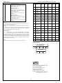
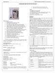
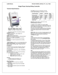
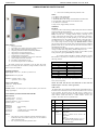
USER MANUAL
PROTON POWER CONTROL PVT. LTD., PUNE
GSM BASED MOTOR PROTECTION UNIT
•
DEC: Down scroll the parameter & parameter value.
LED’S:
1. UV (RED): Under Voltage Fault.
2. OV (RED): Over Voltage Fault.
3. SPP/UB/RP (RED): SPP, Voltage Unbalance& Reverse Phase Fault.
4. UL/CUB (RED): Under Load & Current Unbalance Fault.
5. OL (RED): Over Load Fault.
6. Relay (Green): Supply Healthy (No fault)
WORKING:
Run Mode:
At Power On, under normal working condition, Relay indication led will blink
and glow steady after power on delays.
Steady glow of Relay led indicates Relay on condition. Unit will enter ‘Run
Mode’, and will have a scrolling parameter display consisting of R-Y
Voltage, Y-B Voltage, B-R Voltage & R, Y, B current drawn by each phase.
In Run mode Relay may turn OFF depending on the occurrence of fault,
ALARM indications for the particular fault will blink on the front panel of
unit. Faults such as over / under load, will turn off relay and faults such as
over / under voltage will turn off voltage relay. Manual control for restart
after occurrence/clearance of fault has been programmed therefore user has to
press decrement key to restart the unit. The unit will resume Run mode if
fault disappears after delay.
The Front panel provides fault indication by blinking red led’s for over/under
voltage, over/under load, single phasing, unbalance & phase reverse.
User can view the parameters in Run mode display and can ‘Hold’ any Run
mode parameter by pressing increment key in RUN mode.
Salient Features:
1.
Fully programmable
2.
No auxiliary power supply required for controller operation.
3.
SMS controlled start/stop and remote monitoring.
4.
Complete protection from electrical unhealthy condition.
5.
All parameters are password protected.
6.
All parameters are settable through front key.
7.
LED indications for alarm (fault).
8.
Scrolling display of parameters, one by one in scroll mode.
9.
Onsite Voltage and current Calibration.
10. Four bright 7 segment display on unit.
11. Inverse Time trip curve for over load fault.
In Overload condition when Itcr is selected as NO then it will take
2sec.(settable) to trip Relay & if selected as yes then the relay will Trip as
following condition.
% of set point
Trip time(sec.)
110
120
130
140
150
200
300
400
40
20
15
10
8
5
2
1
The Motor protection unit continuously scans the faults like Under
Voltage, Over Voltage, SPP, Reverse Phase, Voltage Unbalance, Under Load,
Over Load, Current unbalance.
Technical Specification:
Input Supply: 3 Phase 415 V, 50 HZ AC (3 Phase 4 wire)
Input Current: 0-18 A per phase
Accuracy:-1] Voltage 0.25% ± 1 dgts.
2] Current 0.25% ± 1 dgts.
E.g.:- If Overload set point is 8A & actual current is 9.6A then it will take
20sec.(120%) to trip Relay.
Output contact Rating:
3 Pole 415V, 18Amp Contactor
7 A at 250 volt
NOTE: The under load and Over load faults will not sense until the
feedback input is received (i.e. contact gets closed).
GSM Control:
The GSM control can be enabled or disabled using the programming menu. If
the GSM control is enabled, the motor will start if “START” sms is received
by the controller. The motor stops if any fault occurs or “STOP” sms is
received by the controller. If any fault occurs the controller will send an sms
which contains current fault status to 3 mobile numbers stored in the
controller. The control sms are as explained below.
Auxiliary Power: - No External power is required (Draws power from the
voltage signal Inputs)
GSM MODEM: Quad-Band 850/ 900/ 1800/ 1900 MHz
Environmental:
1] Working Temp : 0 to 55º C
2] Storage Temp : 10 to 70º C
3] Relative humidity: 0–95 % non-condensive
4] Warm up time
: 30 Sec
Enclosure:1] Mounting
2] Position
3] Enclosure
4] Terminal
KEY’S:
•
•
Sr.
No
: Panel mounting.
: Panel.
: 125(W) X 275 (L) X 210(H) mm.
: Screw ON Terminals.
SET: This key is used to change the controller from RUN mode to
FUNCTION mode for Parameter setting & to save the modified
setting in Function mode
INC: Up scroll the parameter & parameter value.
1 SMS
Function
START
Starts the motor
STOP
Stops the motor
STATUS?
Replies the present status of the controller
to the sender.
REG
NUM1
**********
Registers the number inside the controller
phonebook.
NOTE: 3 numbers can be stored in the
phonebook.
Syntax
:
REG<space>NUM1<space>**********
(** represents 10 digit mobile number.)
Eg 1. If user sends :-
USER MANUAL
PROTON POWER CONTROL PVT. LTD., PUNE
REG NUM1 9191919191
To the controller , the controller writes the
mobile number 9191919191 to the 1st
location of phonebook.
Eg 2. If user sends :REG NUM2 9191919191
To the controller , the controller writes the
mobile number 9191919191 to the 2nd
location of phonebook.
NOTE: 3 numbers can be stored in the
phonebook.
Eg 3. If user sends :REG NUM3 9191919191
To the controller , the controller writes the
mobile number 9191919191 to the 3rd
location of phonebook.
NOTE: 3 numbers can be stored in the
phonebook.
Sr
No
Parameter
Name
Disp
msg
Def
value
Min
Limit
Max
Limit
Unit
1
Uu
330
0
380
V
ou
460
410
550
V
Ub
60
0
100
V
Cub
50
0
100
% OL
rP
yes
no
yes
NA
6
Under
Voltage
Over
Voltage
Voltage
Unbalance
Current
Unbalance
Reverse
Phase
Under Load
UL
4.00
0.00
10.0
A
7
Over Load
oL
12.00
5.0
25.0
A
8
Under
Voltage trip
time
Over
Voltage trip
time
SPP Trip
Time
Unbalance
trip time
Under Load
trip time
It
characteristi
c
Relay ON
time
Auto Reset
selection
GSM Enable
Uutr
4
1
10
Sec
outr
2
1
5
Sec
SPtr
2
1
5
Sec
Ubtr
2
1
5
Sec
ULtr
60
1
90
Sec
Itcr
yes
No
yes
NA
rLon
10
5
300
Sec
rSt
yes
No
yes
NA
Gsm
no
no
yes
NA
2
3
4
5
NOTE:
1. If any fault occurs to the motor, controller will send sms only to the 3
numbers registered in the phonebook.
2. Motor can be Started/Stopped by sending START/STOP sms through any
number.
3. If STATUS? Sms is sent to the controller, the controller will reply the
motor status only to the number from which STATUS? sms was received.
Thus any number can inquire the controller status.
9
10
11
12
Function Mode:
Function key is used to enter ‘Function mode’ to view/change
settings. When function key is pressed for 2-3 seconds then “pwrd” message
is displayed and then “0000”, user can change the password by pressing
increment and decrement keys, to enter the password press enter. If user enters
correct password the controller enters Function mode, after entering Function
mode, settings can be viewed by going on pressing the Function key. The
default password for the unit is 5.
13
14
15
16
Note:
Over Load fault trip time is applicable as per Inverse trip time curve.
Terminal Layout:
3P 415V 50Hz
AC SUPPLY
R
Y
B
N
E
O UTPUT
R
Y
B
TM
PROTON
PROTON POWER CONTROL PVT. LTD.
S. NO. 28, JAGTAP DAIRY,
PIMPLE NILAKH, PUNE – 411027.
TEL: 020-2727 0800, 27276777
TEL/FAX: 020-2727 0100
MOBILE: 9764885010/9422009655
E-MAIL: [email protected]
[email protected]
2