1
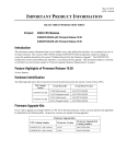
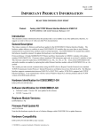
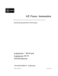
January 18, 1998 GFK-1490A IMPORTANT PRODUCT INFORMATION READ THIS INFORMATION FIRST Product: IC693CPU364 CPU Module with Ethernet Interface IC693CPU364-AB with Firmware Release 9.01 Introduction This document contains information that is not available in any other publication; therefore, we recommend you save it for future reference. This document discusses the features of the CPU module IC693CPU364. This module provides two functions in one module: (1) it serves as a High Performance CPU, and (2) it provides Ethernet communications capability with its embedded (built-in) Ethernet Interface. CPU364 Feature Highlights (Release 9.00) CPU Features • Software Floating-Point. The CPU364 supports all of the floating-point function blocks that are currently supported by the CPU352. They are implemented in firmware using floating point emulation in the CPU364. These Floating-Point math function blocks are described in the IC693 PLC Reference Manual. • User memory totals 240K bytes. %R, %AI, and %AQ references are configurable up to 16K of %R, 8K of %AI and 8K of %AQ memory using the MS-DOS PLC programming software, version 9.02 or later. These three references will be configurable up to 32K in the next release (2.2) of the Windows PLC programming software. Configuration instructions for this feature are described in the MS-DOS IC693 Programming Software User’s Manual, and will be included in on-line help in the future release of the Windows PLC Programming Software, version 2.2. • A new function block, the Sequential Event Recorder, is available in this module. This function block can be used to record up to 1024 samples of 32 individual discrete (bit) references. This function block is described in the IC693 PLC Reference Manual. • Break-free SNP. The SNP protocol no longer requires a break to operate. This allows SNP to work over a wider variety of modems. Ethernet Features • The CPU364 supports connection to an Ethernet network via either (but not both) of two built-in Ethernet network ports: AAUI: Capability is provided for connection to various types of Ethernet LANs via an external AAUI 1. transceiver connected to the AAUI port. The IC649AEA103 AAUI transceiver may be used, or the user may supply a different model that meets AAUI standards. 10Base T: The CPU364 provides direct connection to a 10BaseT (twisted pair) Ethernet LAN from its 2. 10BaseT port. • The CPU364 provides network communications using SRTP (Service Request Transfer Protocol) over standard TCP/IP (Transmission Control Protocol / Internet Protocol) on an Ethernet Local Area Network (LAN). The CPU364 supports communications with other IC693 PLCs and/or IC697 PLCs equipped with TCP/IP Ethernet Interfaces, and with MS-DOS TCP/IP programming software and applications which use the TCP/IP Host Communications Toolkit (HCT) Software. MS-DOS and Windows are registered trademarks of Microsoft Corporation 2 Important Product Information GFK-1490A Hardware Identification The following table shows the revision level of the circuit boards used in this version (-AB) of the IC693CPU364. Note that no firmware upgrade kits are listed because this is the initial release of this module. CPU364 Hardware Information CPU Model (Version) IC693CPU364-AB Circuit Board ID Circuit Board Version Main Firmware Version Boot Firmware Version CX3A1 (CPU) 44A739579-G01R05 or later 9.01 (45A1) 9.00 (33A1) EE3A1 (Ethernet) 44A739599-G01R04 or later 1.00 (41A1) 1.00 (33A1) Firmware Upgrade Kits If you wish to upgrade an existing CPU364 to firmware version 9.01, you may purchase the applicable kit identified in the following table. All previous versions are capable of being upgraded. Firmware 9.01 Upgrade Kit Catalog Number CPU Catalog Number Firmware Upgrade Kit Catalog Number IC693CPU364-(all versions) 44A747767-G01 Functional Compatibility The CPU364 module is compatible with existing IC693 hardware. Operating Notes User Flash Contents User information, consisting of program, configuration, CPU ID (used for SNP communications), and status tables in RAM memory, will automatically be cleared if the CPU firmware in flash memory is changed. So you will need to restore these if upgrading firmware. A recommended procedure is to first back up your user information from RAM memory to Flash memory. Then write your new firmware to Flash memory (firmware is stored in a different location in Flash memory than that used for storing user information such as program, configuration, etc.). Finally, write your user information back out of Flash into RAM memory. As an alternative, your user information (program, configuration, etc.) can be restored from a computer-based backup program folder using your PLC programming software. The SNP ID must be set separately, using the programming software or the Hand-Held Programmer (HHP). Option Module Revision Requirements • All IC693 Ethernet Interface (IC693CMM321) modules used with this CPU should be updated to IC693CMM321 firmware release 1.10 or later. This is also a requirement of the TCP/IP Ethernet version of the MS-DOS programming software. • FBC version 3 or later is required for this CPU. Writing Flash Using a Serial Programmer When writing very large programs to flash memory, it may be necessary to increase the Windows programming software request timeout value to avoid receiving a request timeout message. An upper bound of 25 seconds is typically satisfactory. For further details, see the item “Store of Program or Reference Tables to Flash may Cause Loss of Ethernet Communications” later in this section. Important Product Information 3 GFK-1490A Power Supply Requirements The CPU364 requires one of the three following PLC power supplies: IC693PWR321 (Rev. K or later), IC693PWR322, or IC693PWR330. Power consumption of the CPU364 and its supporting devices are listed below: • • CPU364 requires 1.1A @ +5VDC (= 5.5 Watts). If used, the external AAUI transceiver will require a maximum of 400 mA, or 2.0 Watts (limited by the AAUI standard). Consult the transceiver documentation to obtain its exact power requirements. The IC649AEA103 transceiver requires 380 mA at 5 VDC (=1.9 Watts). • If used, the converter in the IC690ACC901 serial cable assembly requires 100 mA at 5 VDC (=0.5 Watts). • If used, the IC690ACC900 RS-422/RS-485 to RS-232 converter requires 170 mA at 5 VDC (=0.85 Watts). Unreliable AAUI 10Base2 Ethernet Transceiver (IC649AEA101A) The external AAUI 10Base2 Ethernet transceiver, available as catalog number IC649AEA101A, has been discovered to operate unreliably under some conditions. This part is no longer offered. Instead, please use catalog number IC649AEA103. Configuration via Serial Port is Required Before Using Ethernet Communications The Ethernet Interface within the CPU module cannot operate on a network until a valid IP address is configured. The necessary Ethernet addressing information must be configured prior to actual network operation. Two methods are available: 1. Perform the initial configuration using a PLC Programmer connected through the PLC power supply serial port. 2. Connect a serial terminal to the station manager port (port 1) of the CPU364. Then use the CHSOSW command to enter a temporary IP address. The Ethernet Interface can then be accessed over the network (such as by an Ethernet PLC Programmer). See TCP/IP Ethernet Communications for the IC69* Station Manager Manual for details. Proper IP Addressing is Always Essential The CPU364’s embedded Ethernet Interface must be configured with the correct IP Address for proper operation in a TCP/IP Ethernet network. Use of incorrect IP addresses can disrupt network operation. Refer to TCP/IP Ethernet Communications for the IC69* User’s Manual for important information on IP addressing. AAUI Cable Attachment Power to the PLC must be turned off whenever the transceiver (AAUI) cable is connected or disconnected at the CPU364 or at the transceiver. Sudden changes in power supply loading caused by connecting or disconnecting the transceiver with power on may result in unexpected operation of the CPU364 or other modules. Connecting the transceiver with power on may also blow the protective Ethernet interface fuse. A blown fuse can be replaced in the field. Refer to TCP/IP Ethernet Communications for the IC69* User’s Manual for instructions. SQE Enable The Ethernet Interface within the CPU364 requires that the SQE test signal be enabled on the transceiver connecting it to the Ethernet LAN. If you are using an external transceiver, make sure your transceiver has SQE enabled. COMMREQ Operation The CPU364 receives Ethernet Communications Request (COMMREQ) function blocks at a unique Rack/Slot and Task address. Each COMMREQ sent to the CPU364 must be addressed to SYSID = 0001 (= Rack 00 / Slot 01, the location of the CPU364) and to TASK = 21 decimal (Note: TASK = 0 is used in COMMREQs sent to the IC693CMM321 Ethernet module). Please refer to the TCP/IP Ethernet Communications for the IC69* User’s Manual for further COMMREQ function block details. 4 Important Product Information GFK-1490A Serial Load/Store of Register Table Causes Loss of Communications to Ethernet Programmers A load or store of the PLC Register (%R) table from a PLC Programmer connected through the CPU serial port (using the connector on the PLC Power Supply) can cause Ethernet applications that use the PLC programmer communications window to lose communications. This condition occurs when the load/store operation requires more than 10 seconds to complete (called a “timeout”). For example, transferring a large %R table to the CPU (even at 19,200 baud) may cause a timeout. If this occurs, the Ethernet Interface will post two or more PLC faults with the text “LAN system-software fault; resuming”, and fault-specific data starting with 080008 and/or 080042. In addition, faults with text “Bad remote application request; discarded request” (1B0021) and “Local request to send rejected; discarded request” (110005) may occur. When these faults occur, the STAT LED on the CPU364 will be turned off to indicate posting of faults to the PLC fault tables. Normal operation will resume once the transfer completes. The STAT LED can be reset using the Station Manager OK command Ethernet Programmer May Briefly Lose Communications When Configuration Stored Storing a PLC configuration containing Ethernet configuration values may require the Ethernet Interface to restart itself in order to use any changed configuration values. When the Ethernet Interface restarts, an Ethernet PLC Programmer will briefly report a loss of communications. PLC faults similar to those listed under “Serial Load/Store of Register Table Causes Loss of Communications to Ethernet Programmers” above will occur; and the STAT LED on the CPU364 will be turned off to indicate posting of faults to the PLC fault tables. In some cases, a ten second delay may occur before loss of communications is detected. Normal operation will resume once the Ethernet Interface restarts. The STAT LED can be reset using the Station Manager OK command. When the PLC configuration is stored from an Ethernet PLC Programmer, the communications loss occurs immediately after successful completion of the store. Attempts to store configuration plus logic and/or reference tables in one operation can fail. However, storing configuration separately from logic or reference tables will always succeed. Store of Program or Reference Tables to Flash May Cause Loss of Ethernet Communications While storing the PLC program, configuration, and/or reference tables from PLC RAM memory into Flash memory, Ethernet data communications may be lost. Normal data transfers are temporarily suspended during the Flash store operation. Ethernet data transfers (such as used by an Ethernet PLC Programmer connection) during a Flash store operation will fail when the Flash store exceeds the 10-second maximum period allowed for completion. Upon completion of the store to Flash operation, normal operation will resume. RUN Mode Program Store A store of a folder containing large (greater than 14kb) program blocks from a PLC Programmer connected through the Ethernet port on the CPU364, or through an IC693CMM321 Ethernet module, may fail and result in momentary loss of communications. This condition has been observed only when attempting to store a large program to a PLC which is in RUN mode, and which is configured to use a limited communications window. These conditions cause the store operation to take the maximum possible period to complete. The failure may occur if this period exceeds 10 seconds for an individual program block. If this problem does occur, one of the following options may be used to complete the store operation successfully: 1. Change the PLC configuration to use Run-to-Completion mode instead of a Limited Communications Window for the store operation. 2. Change the PLC from RUN to STOP mode to complete the store. 3. Structure the folder being stored to eliminate large program blocks or subroutine blocks. This will minimize the chance that any single block will take longer than the maximum 10-second period allowed for storage of that block. Store of Large Program Blocks from Older Ethernet Programmers If an attempt is made to store a folder which contains large (greater than 14kb) program blocks or subroutine blocks using the IC693 MS-DOS programming software, Ethernet Version 6.6 or earlier, the store attempt may fail with the Important Product Information 5 GFK-1490A message “(S83) Program size too large for PLC or invalid user program” displayed. If this problem is observed, the following options may be used to complete the store operation successfully: 1. Update the IC693 MS-DOS programming software, Ethernet Version, to a more recent version that can be run in a DOS box under the Microsoft Windows NT/95 operating system. IC693 MS-DOS programming software, Ethernet Version 9.02 or later is recommended. (Note: In order to configure the CPU364, Version 9.02 or later is required.) This option requires Microsoft Windows NT or Microsoft Windows 95 to be installed on the PC that executes the programming software. 2. If the ladder contains large (greater than 14kb) program blocks or subroutine blocks, then restructure the ladder to use smaller blocks, either by simplifying the program or by making use of more subroutine blocks that are each smaller than 14kb in size. 3. If neither of the previous options is practical, then the following work-around for the problem may be successful. Modify the CONFIG.SYS file on the MS-DOS programmer PC to decrease the maximum TCP segment size used by the Beame & Whiteside driver. This may be accomplished by changing the values used on the line containing the following: DEVICE=C:\BWTCP\TCPIP.SYS 1460 2920 20 Change the value 1460 to 1024, and change the value 2920 to 2048. Ethernet Exception Log Event c/10a & c/10b These two Ethernet exception log events are meant to signal possible problems with the physical network, such as an unterminated cable. Occasionally these log events can occur under normal network operation if a temporary heavy burst of traffic on the network prevents normal transmission onto the network. These events are an indication of a problem with network loading, and will cause the STAT LED to turn off. Often there are no other apparent symptoms. If this occurs frequently, or continuously, it bears reporting to your network administrator or whomever is responsible for network maintenance. Managing Channels and TCP Connections In certain conditions, the supply of TCP connections can be totally exhausted. When you issue a COMMREQ to establish a read or write channel, a TCP connection is created, the transfer(s) are made, then upon completion of all the transfers, the TCP connection is terminated. If an application is constructed so that it rapidly and repeatedly establishes a channel with only one repetition (one transfer), the available TCP connections for the Ethernet Interface may be totally exhausted. Specifically, if your ladder program for issuing COMMREQs is constructed so it does the following, all available TCP connections can quickly be used up: The number of repetitions (Word 9) in an Establish Read or Write Channel COMMREQ is set to 1, and a new COMMREQ is issued repeatedly and immediately upon completion of the prior one. It is recommended you use “Channel Re-tasking” to avoid exhausting TCP connections. Re-tasking is described in the TCP/IP Ethernet Communications for the IC69* User’s Manual. 6 Important Product Information GFK-1490A Problems Resolved in Firmware Version 9.01 SNP Master mode on CPU Ports With some very large configurations and version 9.00 firmware, after a power-cycle, CPU ports set up for SNP Master would need to have their configuration re-stored for the protocol to accept COMM_REQs. This is corrected in version 9.01. Online Changes to Reference Tables Making online changes with the programmer to reference tables could result in a watchdog timeout. This has been corrected in version 9.01. Read from Flash In version 9.00, reading a folder from flash memory could result in the PLC going into a faulted state. This is corrected in version 9.01. CPU364 Restrictions and Open Problems Trace LZ While a local Station Manager “TRACE LZ” troubleshooting command is in effect at an Ethernet Interface, do not issue Station Manager “REM <node> TEST” commands to it from a remote Interface. Doing so can cause errant behavior, including module lockup and loss-of-module in the PLC fault table. Ethernet Firmware Update Mode When the Ethernet (daughterboard) firmware is in update mode, no fault is logged on the PLC to indicate this. The firmware update mode is indicated by the flashing of the EOK, LAN, and STAT LEDs. The LEDs flash in unison. Multiple Log Events The Ethernet Interface sometimes generates multiple exception log events and PLC Fault Table entries when a single error condition occurs. Under repetitive error conditions, the exception log and/or PLC Fault Table can be completely filled with repetitive error messages. Documentation Instructions for using the IC693CPU364 module can be found in the latest version of the following manuals: General Configuration Instructions: IC693 PLC Programming Software User’s Manual. Ladder Logic Programming: IC693 PLC Reference Manual. Ethernet-Specific Instructions: TCP/IP Ethernet Communications for the IC69* PLC User’s Manual. Also see the TCP/IP Ethernet Communications for the IC69* Station Manager Manual Important Product Information 7 GFK-1490A IC693CPU364 Data a47501 Single slot CPU module with embedded Ethernet Interface 8 (CPU baseplate + 7 expansion and/or remote) 1.1 Amps from +5 VDC supply 25 MegaHertz 80386EX 2.69x2.69x6.1 mm, 125V, 1A, slow acting 0 to 60 degrees C (32 to 140 degrees F) ambient .22 milliseconds per 1K of logic (Boolean contacts) 240K (245,760) Bytes. Note: Actual size of available user program memory depends on the amounts configured for the %R, %AI, and %AQ configurable word memory types (described below). 2,048 Discrete Input Points - %I 2,048 Discrete Output Points - %Q 1,280 bits Discrete Global Memory - %G 4,096 bits Internal Coils - %M 256 bits Output (Temporary) Coils - %T 128 bits (%S, %SA, %SB, %SC - 32 bits each) System Status References - %S Configurable in 128 word increments, from 128 to 16,384 Register Memory - %R words with DOS programmer, and from 128 to 32,640 words with Windows programmer Ver. 2.2 when available. Configurable in 128 word increments, from 128 to 8,192 Analog Inputs - %AI words with DOS programmer, and from 128 to 32,640 words with Windows programmer Ver 2.2 when available. Configurable in 128 word increments, from 128 to 8,192 Analog Outputs - %AQ words with DOS programmer, and from 128 to 32,640 words with Windows programmer Ver. 2.2 when available. System Registers (for reference table 28 words (%SR) CPU Type Total Baseplates per System Load Required from Power Supply Processor Speed Processor Type Ethernet fuse, replaceable Operating temperature Typical Scan Rate User Memory (total) viewing only; cannot be referenced in user logic program) Timers/Counters Shift Registers Built-in Serial Ports Communications Override Battery Backed Clock Interrupt Support Type of Memory Storage PCM/CCM Compatibility Floating Point Math Support >2,000 (depends on available user memory) Yes 1 (uses connector on PLC Power Supply). Supports SNP/SNPX. Requires option modules for RTU and CCM. Ethernet (internal) – AAUI or 10Base T. AAUI requires external transceiver. 10Base T is direct. Ethernet (additional) – Supports Ethernet option modules. LAN – Requires option modules for Genius, Profibus, FIP. Yes Yes Supports the periodic subroutine feature. RAM and Flash Yes Yes, firmware-based Note: On some modules the LED labeled “PS PORT” may say “SNP” instead; otherwise, the modules are identical. PS SNP PORT EOK LAN STAT CPU 364 CPU 364 ON OFF ETHERNET RESTART PORT 1 RS-232 AAUI 10BASE T FRAME