1
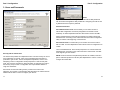
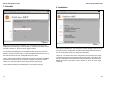
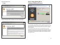
SP Controls, Inc.
CatLinc™ Net
User’s Manual SP Controls, Inc.
930 Linden Avenue
So. San Francisco, CA 94080
(877) 367-8444 toll free
(650) 392-7881 fax
Contents
Important Safety
Contents
Instructions............................................... 1
FCC Compliance........................................................................ 1
Part I. Introduction.................................................................... 2
Technical Overview....................................................................... 3
CatLinc Net Access Security....................................................... 3
Part II. Configuration
Configuration and Installation Overview....................................
Configuration Setup.....................................................................
1. What You Need.......................................................................
2. Connecting the CatLinc Net to Your PC..............................
Configuration................................................................................
1. Finding Device........................................................................
2. Networking Essentials...........................................................
3. Users and Passwords............................................................
4. Hours of Use...........................................................................
5. Save/Download Settings.......................................................
4
5
5
6
7
7
8
11
15
18
1. Connecting the CatLinc Net to the LAN.............................. 19
2. Connecting the CatLinc Net to the SmartPanel................. 19
3. Powering the CatLinc Net..................................................... 19
Part IV. Using CatLinc Net.................................................... 21
Status and Control.................................................................
Statistics ................................................................................
Schedule.................................................................................
Installation..............................................................................
Help.........................................................................................
Part VII. Technical Specifications...................................... 34
Appendix I. Upgrading Product Firmware..................... 35
Copyright ................................................................................... 38
Warranty........................................................................................ 38
Part III. Installation................................................................... 19
1.
2.
3.
4.
5.
Part VI. Troubleshooting....................................................... 31
21
25
27
28
29
Part V. Using CatLInc Net to Configure......................... 30
Additional Devices
Configuration Worksheet..................................................... 39
Important Safety Instructions
1) Read these instructions. 2) Keep these instructions.
3) Heed all warnings.
4) Follow all instructions.
5) Do not use this apparatus near water.
6) Clean only with dry cloth. 7) Do not block any ventilation openings. Install in accordance with the manu
facturer's instructions. 8) Do not install near any heat sources such as radiators, heat registers,
stoves, or other apparatus (including amplifiers) that produce heat. 9) Protect the power cord from being walked on or pinched particularly at
plugs, convenience receptacles, and the point where they exit from the appa
ratus. 10) Only use attachments/accessories specified by the manufacturer. 11) Unplug this apparatus during lightning storms or when unused for long
periods of time. 12) Refer all servicing to qualified service personnel. Servicing is required
when the apparatus has been damaged in any way, such as power-supply
cord or plug is damaged, liquid has been spilled or objects have fallen into the
apparatus, the apparatus has been exposed to rain or moisture, does not
operate normally, or has been dropped.
FCC Compliance
This equipment generates radio frequency energy and if not installed in
accordance with the manufacturer's instructions may cause radio interference.
This equipment complies with part 15, Subpart J of the FCC rules for a Class
A computing device. This equipment also complies with the Class A limits for
radio noise emission from digital apparatus set out in the Radio Interference
Regulation of the Canadian Department of Communications. These above
rules are designed to provide reasonable protection against such interference
when operating the equipment in a commercial environment. If operation of
this equipment in a residential area causes radio frequency interference, the
user and not SP Controls, Inc., will be responsible.
Changes or modifications made to this equipment not expressly approved by
SP Controls, Inc., could void the user's authority to operate the equipment.
Part I. Introduction
CatLinc™ Net Web Interface
The CatLinc™ Net is a network interface and Internet gateway to the SP
Controls SmartPanel™ Control System, and by extension to the A/V equip
ment the SmartPanel controls. It is a plug-and-play device that requires no
programming. The CatLinc Net provides the following features:
- Remote Monitoring and Control: CatLinc Net provides real-time web-
based control and monitoring for the SmartPanel from any Internet connection, anywhere in the world. - Security: With the CatLinc Net you can schedule-lock the SmartPanel,
preventing unauthorized access to projector control during hours when your
school or business is closed. If the projector you control allows 2-way
RS-232 communication, the CatLinc Net can also be configured to email
security notifications if it loses contact with the SmartPanel or the projector.
- Maintenance Support: If the projector you control allows 2-way RS-232 communication, CatLinc Net will send an email alert to maintenance when the projector is nearing the end of its lamp life or if the projector breaks down. Once connected to the network, the SmartPanel and CatLinc Net can be configured and updated over the Internet. Update projector drivers and firmware with the click of a button.
- Information Gathering/Reporting: CatLinc Net can be configured to report
valuable usage information and statistics including total usage hours, usage
by source, and lamp hour tracking. Information on how equipment
is really being used will save you money in future purchasing. The CatLinc
Net can be configured to email maintenance reports on a periodic basis.
SP Controls, Inc. assumes no responsibility for any errors that appear in this
document. Information in this document is subject to change without notice.
1
2
Part I. Introduction
Part I. Introduction
CatLinc Net Access Security
Technical Overview
CatLinc Net is a minimal implementation of an HTTP web server. In addition to
serving HTML pages, it is capable of sending SMTP email, issuing and
responding to ARP requests, and querying Simple Time servers. CatLinc Net
uses RFC-compliant light implementations of the following networking proto
cols: HTTP including SimpleAuth, TCP/IP, UDP, SMTP, and ARP. Its physical
layer is 10mpbs Ethernet. CatLinc Net responds to pings.
Because the CatLinc Net requires a static IP address, it is not compatible
with DHCP.
System Requirements
The CatLinc Net is designed for use with the SP Controls SmartPanel projec
tor control interface. The SmartPanel must be running firmware version 1.01
or higher. Compatible firmware ships in SmartPanels manufactured as of May
of 2003 or later.
You can verify your SmartPanel firmware version by connecting to the
SmartPanel with the SP Controls Product Configuration Utility. The firmware
version of the Panel is displayed in the bottom bar.
CatLinc Net is a proprietary, closed-source, monolithic application running on
an embedded microcontroller. It does not run any operating system, cannot
provide terminal /.shell access, does not contain a file system, et cetera. As a
result it is incapable of being compromised in the manner of a conventional
system and cannot be used to launch DoS attacks, et cetera.
Consequently, security considerations with CatLinc Net are limited to discour
aging unauthorized control of the room A/V systems to which it provides
access, and preventing nuisance reconfiguration of the product (e.g., chang
ing its IP address).
CatLinc Net implements two types of security: User ID/Password based chal
lenges for two levels of access via HTTP's built-in Simple Authorization mech
anism (control-only user, administrator with reconfiguration rights); and IPbased access control screening, which prevents control except from specific
IP address ranges.
Part II. Configuration
Configuration and Installation Overview
The CatLinc Net is configured using the PC-based SP Controls Product
Configuration Utility. The Product Configuration Utility is included in the CD
ROM that ships with the SmartPanel. It is also available for download from our
web site at www.spcontrols.com.
SmartPanel
Firmware Version
FIGURE 1
If you do not have compatible SmartPanel firmware, a firmware upgrade can
be ordered from SP Controls (no. SP2-FW-UPG-V1.10).
A standard active Ethernet connection to your WAN or LAN (hereafter ‘LAN’)
on UTP, STP, or FTP (i.e., CAT5) with a standard RJ-45 termination must be
available at the CatLinc Net installation point.
Note: The CatLinc Net cannot be used with a SmartPanel Master/Slave instal
lation.
3
CatLinc Net can be configured either through RS-232 or TCP/IP. However, the
initial configuration must be made via RS-232. Once it is configured with an IP
address it will be network-addressable and can then be configured via TCP/IP.
Configuration and installation of the CatLinc Net requires the following steps:
1. Initial configuration of the CatLinc Net with a PC or laptop via RS-232
(Part II of this manual),
2. Physical installation of the CatLinc Net with a fully-configured SmartPanel
system (Part III of this manual), and
3. Final connection and control via TCP/IP (Part IV of this manual).
4
Part II. Configuration
Configuration Setup
1. What You Need
To configure the CatLinc Net via RS-232 you will need the following:
-A PC or laptop running the latest version of the SP Controls Product Configuration Utility, version 2.0.41 or higher (required, available for free download from SP Controls at www.spcontrols.com).
-A 12VDC power supply for the CatLinc Net (required).
-A null-modem serial cable or adapter (required - included).
-A LAN connection for your PC/laptop (recommended).
-A LAN connection for your CatLinc Net (recommended).
Part II. Configuration
2. Connecting the CatLinc Net to your PC
The SP Controls Product Configuration Utility is a simple application that can
be used to configure multiple SP Controls products separately or simultane
ously. The Configuration Utility can be run on any Microsoft™ Windows™
based PC or laptop. The Configuration Utility ships with the SmartPanel and
SmartPanel firmware upgrade. It is also available for download on our web
site at www.spcontrols.com.
In addition, you will need the following information from your Network System
Administrator:
- A dedicated static IP address for the CatLinc Net (required). This IP must
be permanently assigned to the CatLinc Net. The CatLinc Net is not
compatible with DHCP.
-The IP address of local LAN gateway (required).
-The subnet mask for the LAN (required).
-The IP address of a time server providing Simple Time on Port 37 via UDP
(recommended - required for time-based functions such as scheduled
lockouts).
- The IP address of an SMTP (mail) server on the LAN (recommended required for email security and maintenance notification).
Note: You will find a Configuration Worksheet (pages 39-40) to facilitate col
lecting necessary information.
FIGURE 2
To connect your PC/laptop to the CatLinc Net for configuration:
1. Apply 9-12VDC power to the CatLinc Net. Power can be drawn from the
SmartPanel (see Part III. Installation - Powering the CatLinc Net, page 20
below).
TIP: You can borrow the 12V power supply from the SmartPanel to power
the CatLinc Net for configuration. Simply unscrew the wires from the cap
tive screw connector attached to the end of the power supply and connect
it to the captive screw connector that ships with the CatLinc Net. Polarity
must be correct, so if you do not see the POWER LED illuminate, try flip
ping the orientation of the wires.
2. Connect a null-modem serial cable (provided) or a serial cable with a nullmodem serial adapter to the COM port on your PC/laptop.
3. Connect the null-modem serial adapter to the male DB9 of the CatLinc Net.
4. Launch the SP Controls Product Configuration Utility on your PC.
5
6
Part II. Configuration
Part II. Configuration
Configuration
2. Networking Essentials
Note on DNS: If your PC or Laptop has a network connection at the time of
installation, you can use DNS to retrieve IP addresses for known domain
names only. You cannot assign a new DNS entry in these fields.
On this page you will configure the CatLinc Net networking information so that
it can be targeted by network devices and browsers and communicate with
the outside world.
1. Finding Device
Select the appropriate COM port in the pull-down menu. Initial configuration of
the CatLinc Net must be via RS-232. Subsequently the unit can be reconfig
ured via TCP/IP by selecting TCP/IP in the drop-down menu and entering the
CatLinc Net's IP Address and pressing ENTER.
FIGURE 4
Room Name: Assign a room name for the CatLinc Net in this field. It will be
displayed on the browser interface, and included for reference in any mainte
nance or security email.
Alerts/Logging/Statistics: The CatLinc Net can be configured to send email
reports of usage information with your SMTP server. Reports can be sent
either weekly or monthly, or when triggered by a web user. Email reports are
sent in plain text to the address specified below under Logs/Statistics.
FIGURE 3
When the Configuration Utility establishes contact with the CatLinc Net the
icon will indicate that the CatLinc Net has been found.
7
If the box labeled Reset Statistics When Logs Sent is checked the CatLinc Net
will compute usage statistics for each weekly or monthly reporting period and
then reset to 0. If it is unchecked, the CatLinc Net will take cumulative usage
statistics for the life of the room unless manually reset from the Status and
Control web page (see page 25).
8
Part II. Configuration
Part II. Configuration
Email Notifications:
The CatLinc Net must be configured with the IP address of an SMTP server
for email notification. See page 10 for more information.
Subnet Mask: Enter the subnet mask for your LAN.
Gateway: Enter the LAN Gateway in this field.
Enter the email address to specify report recipients for each field.
Alerts: The CatLinc Net will send alerts under the following conditions:
- The CatLinc Net resets
- The CatLinc Net loses contact with the SmartPanel
- The SmartPanel loses contact with the projector (for projectors that support
2-way RS-232 Communication)
- The CatLinc Net reestablishes contact with the SmartPanel(for projectors that support 2-way RS-232 Communication)
- The SmartPanel reestablishes contact with the projector (for projectors that
support 2-way RS-232 communication)
- The CatLinc Net loses contact with the time server
Logs/Statistics: CatLinc Net reports statistical and raw usage data via email.
The CatLinc Net sends the following information in the body of a plain-text
email:
In [ROOM NAME] ([IP ADDRESS])
version: [CatLinc Net firmware version]
Last Statistics Reset: 6/23/2003 14:33:20 Hours on 140
Avg Daily 3
Avg Weekly 21
1)
2)
3)
4)
VCR 15%
DVD 33%
Laptop 25%
PC 27%
IP Networking:
MAC Address: The Media Access Control (MAC) Address is a factory-set,
hardware level address the device uses to communicate on the Ethernet. It is
non-configurable.
Server Addresses:
Time Server: Enter the IP address of a time server providing Simple Time on
Port 37 (via UDP). The CatLinc Net uses the time server for all of its timebased functions, such as scheduled lockouts and periodic statistics reporting.
A time server is not required, but without access to a time server the CatLinc
Net will not be able to use these features.
Note: If an existing server providing Simple Time is not available, shareware
implementations for Windows exist. Alternately, if network firewalls allow UDP
access to the outside world, NIST (the US government) provides multiple time
servers.
For more information on CatLinc Net and time servers, see Part II, Section IV
- Time Server on page 15 below.
Use Daylight Savings/GMT Offset: If you are using a time server, select or
deselect Use Daylight Savings depending on your location, and configure the
GMT Offset based on your Time Zone. In the Continental US:
Pacific Standard Time is
Mountain Standard Time is
Central Standard Time is
Eastern Standard Time is
GMT -8
GMT -7
GMT -6
GMT -5
SMTP Server: Enter the IP address of an SMTP (mail) server on the LAN. The
CatLinc Net uses the SMTP server to send email reports and alerts. An SMTP
server is not required, but without access to an SMTP server the CatLinc Net
will not be able to use its email notification features.
IP Address: This is the permanent network address for the CatLinc Net. The
System Administrator for your LAN must assign a static IP address perma
nently to the CatLinc Net. The CatLinc Net is not compatible with DHCP.
9
10
Part II. Configuration
Part II. Configuration
3. Users and Passwords
FIGURE 6
If passwords or ID's are lost or forgotten, reset the CatLinc Net passwords
with the Product Configuration Utility via RS-232. Configuring the CatLinc Net
by RS-232 will never require a password.
Password Protection:
Allow Administration From: In these fields you can restrict access to
CatLinc Net configuration via TCP/IP (configuration via RS-232 is never
restricted). An Admin ID/password will also allow Control access via HTML.
Admin UserID/Password: Users will be prompted for an Admin UserID and
Password when connecting to the CatLinc Net with the Product Configuration
Utility via TCP/IP at the beginning of each session.
Figure 5
Security and the CatLinc Net:
The CatLinc Net provides two independent forms of access security for control
and configuration via TCP/IP; users must successfully pass both forms of
protection to gain access. The first is ID/password protection, where a user
attempting control or configuration will be prompted for a User ID and pass
word. The second is IP restriction. When this option is configured, the CatLinc
Net will only accept control or configuration from a specified IP address or
range of IP addresses.
Allow Control From: In these fields you can restrict control of the CatLinc
Net via HTML. A Control ID/password will not allow access to configuration via
TCP/IP.
Control UserID/Password: Users will be prompted for an Control UserID and
Password when connecting to the CatLinc Net with a web browser via HTML
at the beginning of each session.
NOTE: If both IP restriction and password protection are enabled, users who
pass IP restriction protection must also pass ID/password in order to control or
configure the CatLinc Net.
SP Controls recommends setting security control for the CatLinc Net.
Otherwise, any browser or Configuration Utility directed to the CatLinc Net's IP
address will be able to control or configure your devices.
11
12
Part II. Configuration
Part II. Configuration
IP Restriction:
Examples of IP Restriction:
Administration and control of the CatLinc Net may be restricted to commands
issued from specified IP addresses for additional security. IP restriction in the
Allow Administration From restricts configuration via TCP/IP to commands
originating from specified IP addresses. IP restriction in the Allow Control
From restricts browser control of the CatLinc to commands originating from
specified IP addresses.
Only From: 111.222.255.10
Only From Mask: 255.255.255.255
Result: Use requests from IP address 111.222.255.10 are allowed (may be
subject to password query). Use requests originating from any other IP
Address are disallowed.
A user attempting to access the CatLinc Net from a disallowed IP Address will
be prompted for an ID and Password. They will be unable to pass the pass
word prompt, even if they enter the correct ID/password combination.
Only From: 111.222.255.10
Only From Mask: 255.255.255.0
Result: Use requests from IP addresses 111.222.255.0 through
111.222.255.255 are allowed (may be subject to password query).
Only From: The CatLinc Net will only respond to control or configuration from
the IP address specified here. Restricted IP addresses configured here are
matched against the Only From Mask, allowing restriction to a field of IP
addresses. See below.
Only From: 0.0.0.0
Only From Mask: 0.0.0.0
Result: Use requests are allowed from any IP address (may be subject to
password query).
Only From Mask: Data in the Only From field is summed with the Only From
Mask to determine which bytes are tested for security restriction. A byte of 255
in the Only From Mask field indicates that the use request must match the
corresponding byte in the Only From field. A byte of 0 in the Only From Mask
field indicates that the corresponding byte in the Only From field will be
passed without a check.
Only From: 111.222.255.10
Only From Mask: 0.0.0.0
Result: Use requests are allowed from any IP address (may be subject to
password query).
You can use the Only From Mask in conjunction with the Only From field to
allow a range of IP Addresses access to the CatLinc Net.
Only From: 111.222.255.0
Only From Mask: 255.255.255.240
Result: Use requests are allowed from IP addresses 255.255.255.0 through
255.255.255.15.
NOTE: Users who pass IP restriction must also pass ID/Password protection
(if it is configured) in order to control or configure the CatLinc Net.
13
14
Part II. Configuration
Part II. Configuration
Tack Lamp Hours: When the Track Lamp Hours option is selected, the
CatLinc Net will track projector lamp usage.
4. Hours of Use
Send Lamp Alert when: The CatLinc Net will report via email when the projec
tor lamp has been active for a specified percentage of the projector's lamp life
(specified below in Max. Lamp Hours). For example, Set Lamp Alert when at
50 lifespan will email an alert to the Alert Notification email address when the
projector lamp has been active for 50% of its projected life.
Current Lamp Hours: If you are installing the CatLinc Net with a used projec
tor, enter the current lamp hours in this field. Many projectors track lamp life
and can report it in their onscreen menus. See your projector documentation
for more information.
Max. Lamp Hours: Enter the estimated lamp life of your projector in this field.
See your projector or lamp documentation for this information.
Enable Schedule Based Control: Select Schedule Based Control to config
ure the CatLinc Net to lock, unlock, power on, or power off the SmartPanel at
scheduled times.
FIGURE 7
Time Server
All of the functions described in this section require that the CatLinc Net can
access a time server providing Simple Time on Port 37 (via UDP).
The standard way to maintain coherent time on a network is via time servers.
CatLinc Net uses the simplest, lightest, common protocol, Simple Time
(defined in RFC 868, runs on UN*X systems as part of the universal INETD).
CatLinc Net is configured to use UDP. The CatLinc Net keeps its own time
internally and uses the time server for drift correction. Under normal operation
CatLinc Net will synchronize time very infrequently, on the order of fifteen
times a week. CatLinc Net can function without access to a time server.
However, all of the functions described in this section will be disabled.
Note: If a time server providing Simple Time is not available, shareware
implementations for Windows exist. Alternately, if network firewalls allow UDP
access to the outside world, NIST (the US government) provides multiple time
servers.
15
Times can be entered in a variety of formats, including:
10:15 PM, 22:00, 10 PM
Locking the SmartPanel
The SmartPanel can be locked in order to prevent unauthorized use of A/V
equipment. When the SmartPanel is locked, it cannot be powered on; all other
functions continue to work. There is therefore no possibility that a projector will
ever be locked on during use. The SmartPanel can always be unlocked manu
ally from the Control web page (see page 23 for more information).
Note: If your CatLinc Net is controlling a SmartPanel equipped with a keylock
peripheral (SP Controls part no. SLB-MINI-KEYLOCK), an UNLOCK com
mand from either source will override any LOCK command. For example, if
the keylock peripheral is set to UNLOCKED and the CatLinc Net is set to lock
out the Panel, the SmartPanel will be UNLOCKED.
Unlock At: The CatLinc Net will unlock the SmartPanel at this time.
Turn On: At this time, the CatLinc Net will turn on the SmartPanel and projec
tor. The effect is identical to pressing POWER ON on the SmartPanel.
16
Part II. Configuration
Turn Off: At this time, the CatLinc Net will turn off the SmartPanel and projec
tor. The effect is identical to pressing POWER OFF on the SmartPanel.
Part II. Configuration
5. Save/Download Settings
Re-Lock At: The CatLinc Net will lock at this time. The Panel will remain
locked until the next scheduled UNLOCK event.
Tip: Be sure to set an Unlock At value after every instance of Re-Lock At.
Once the SmartPanel is locked, it will remain so for any number of days until it
reaches the next scheduled Unlock At time. In the sample configuration pic
tured above (Figure 7), the SmartPanel will be locked all weekend from Friday
night at 5:30 PM until Monday morning at 7:00 AM.
Tip: If a SmartPanel has been locked with a scheduled lock-out, it can be
unlocked manually with a web browser by selecting UNLOCK on the
STATUS AND CONTROL web page. See page 23 below for more information.
FIGURE 8
When configuration is complete, click on the Download Settings button. You
will see a progress bar indicate progress, and a message will indicate suc
cessful download to the product.
Configuration information is stored in a non-volatile memory. The CatLinc Net
can be unplugged for any length of time without losing its configuration infor
mation.
Currently, CatLinc Net room configurations cannot be saved to your PC.
However, iIf you need to configure multiple CatLinc Nets, you can reuse con
figuration settings. When you connect a CatLinc Net to the Configuration
Utility for the first time, you will be asked “This product has not been config
ured. Would you like to keep the settings you used to configure the last
CatLinc Net?” Select YES to load the same configuration information for the
new unit. You will then need to change the specific values that are unique to
each unit, such as the static IP address.
17
18
Part III. Installation
Part III. Installation
The CatLinc Net must be connected to 1) the SmartPanel, 2) your LAN, and
3) a 12VDC power supply.
NOTE: When the CatLinc Net is first connected to the SmartPanel it will
retrieve important configuration information from the Panel which will affect its
display. When the CatLinc Net is first connected, you should not attempt to
access the CatLinc Net with a web browser or the Configuration Utility for at
least 60 seconds while it completes this process.
1. Connecting the CatLinc Net to the LAN
An active Ethernet connection must be available at the CatLinc Net over a
CAT5, 5e, or CAT6 twisted pair network cable terminated in a standard RJ-45.
Connect the RJ-45 on the Ethernet cable to the RJ-45 female connection
labeled ETHERNET on the CatLinc Net. When The CatLinc Net is powered,
the green LED labeled LINK will illuminate when an ethernet connection is
present.
2. Connecting the CatLinc Net
to the SmartPanel
SmartPanel Configuration Port
The CatLinc Net draws 9-12VDC. It does not ship with a power supply. Power
should be drawn from the back of the SmartPanel. If you want an independent
power supply for the CatLinc Net, a 12V power supply can be ordered sepa
rately from SP Controls (part no. SP2-PS).
Power polarity must be correct or the CatLinc Net will not work. Connection
should be as follows:
White Wire: 12VDC
Black Wire: Ground
Power may be drawn from the captive screw connectors landing on the posi
tion labeled POWER on the SmartPanel. Wires should be brought to the
CatLinc Net from the positions labeled +12VDC and GND (see Figure 10).
Alternately, the CatLinc Net can be powered from the SmartPanel IR/SERIAL
port. On the SmartPanel PROJECTOR CONTROL port, bring a wire from the
captive screw connector position labeled +12V and the position labeled GND
(see Figure 11).
CatLinc Net Power
The SmartPanel must be configured and
installed normally for use with the CatLinc
Net. See the SmartPanel Configuration and
Installation Guide for more information.
The CatLinc Net cannot be used in an instal
lation with two SmartPanels connected in a
Master/Slave configuration.
3. Powering the CatLinc Net
To
CatLinc Net
CatLinc Net
FIGURE 9
The CatLinc Net connects to the female DB9
labeled CONFIGURATION PORT on the
back of the SmartPanel. Attach the CatLinc Net’s male DB9 RS-232 cable to
the SmartPanel CONFIGURATION PORT.
SmartPanel Control Port
White Wire to
CatLinc Net 12VDC
To 12VDC
FIGURE 10
Black Wire to
CatLinc Net GND
FIGURE 11
Note: If you extend the RS-232 connection between the SmartPanel and the
CatLinc Net with an intermediate Serial Cable, SP Controls strongly recom
mends you make the extension with a serial cable with all nine pins wired
straight through. For the CatLinc Net DB9 pinout, see Part VII. Technical
Specifications on page 34.
19
20
Part IV. Using CatLinc Net
Once the CatLinc Net is configured and installed, the CatLinc web server is
accessible by any web browser. Simply direct a browser to the static IP
address assigned to the CatLinc Net.
Note: Although CatLinc Net has been tested on various browsers, it is possi
ble that non-standard browsers will exhibit display or control quirks. Please
contact SP Controls ([email protected]) if you have any browser-related
questions or problems.
Part IV. Using CatLinc Net
The SmartPanel display does not auto-update to reflect changes that may
have been made in the room. Refresh your browser periodically to retrieve
current state information.
The Status and Control page gives the following information and control:
Location
The CatLinc Net will report the name configured in the ROOM NAME field
(see page 8).
Time
If your CatLinc Net is connected to a time server, the CatLinc Net will report
current time in this field. Refresh your browser page to update the time dis
play. See Part II, Section 4 - Hours of Use on page 15 for more information.
1. Status & Control
SmartPanel Power
Click on the Projector ON or Projector OFF button to control Projector power.
Active Input
Volume Level
Indicates Active
Connection to Panel
SmartPanel Receiving
Feedback from
Projector
Manual Security Lock
CatLinc Net is
Scheduled for lockout
FIGURE 12
The Status and Control page is the heart of the CatLinc Net interface with the
SmartPanel room. This page displays real-time status information and allows
instantaneous control of the SmartPanel. Selecting buttons on the virtual
Panel has an identical effect as pressing the physical button on the
SmartPanel.
Note: The Status and Control web page displays a Small Chassis SmartPanel
(SP2-SMCHAS), even if you are controlling a Large Chassis SmartPanel
(SP2-CHAS). This will not affect control.
21
The SmartPanel power on sequence communicates the projector’s initializa
tion process with the READY and WARMUP LEDs. The CatLinc Net will dis
play the SmartPanel’s power on sequence. For example, the red LED labeled
WARMUP will illuminate while the projector is warming up and is not yet ready
to accept commands. For a complete disucssion of the SmartPanel power-on
sequence, see the SmartPanel Configuration and Installation Guide.
Input Selection
Select any input selection button on the Panel to change Panel and Projector
inputs. The selected input is indicated by a darker shade of blue.
Note: Some projectors may take several seconds to change inputs, so there
may be a slight delay between making a selection on the Status and Control
web page and the projector switching.
The CatLinc Net retrieves input names from the SmartPanel. If the input
selection fields are not displayed, verify that the SmartPanel is configured with
input legend names. You can configure your SmartPanel with room names
over the network using the CatLinc Net. See Part V. Using CatLinc Net to
Configure Additional Devices on page 30.
Volume Level
To control volume, click on the VOLUME UP or VOLUME DOWN buttons on
the SmartPanel image.
22
Part IV. Using CatLinc Net
The CatLinc Net will display the Panel's current volume level if the CatLinc
Net is controlling a SmartPanel that has been configured with absolute volume
control, or if it is using an Audio Follow Video Preamp (SP3-AFVP+).
Part IV. Using CatLinc Net
The SmartPanel can be locked with an electronic keylock peripheral (part no.
SLB-MINI-KEYLOCK) or scheduled to lock at certain times with the CatLinc
Net.
If the SmartPanel is configured with relative volume control, the volume dis
play on the Status and Control page will only illuminate when a volume com
mand is being sent.
Note: If your CatLinc Net is controlling a SmartPanel equipped with a keylock
peripheral (SP Controls Part no. SLB-MINI-KEYLOCK), an UNLOCK com
mand from either source will override any LOCK command. For example, if
the keylock peripheral is set to UNLOCK and the CatLinc Net is set to lock the
Panel, the SmartPanel will be UNLOCKED.
For more information on Absolute versus Relative volume control, see the
SmartPanel Configuration and Installation Guide.
Ready/Warm-up Status
The green Ready LED and red Warm-up LED reflect current Panel and
projector states. For a complete discussion on what these LED's indicate, see
the page 22 above, or the SmartPanel Configuration and Installation Guide.
Tip: If a SmartPanel has been locked with a scheduled lockout, it can be
unlocked manually with a web browser by selecting UNLOCK.
For further information on locking the SmartPanel with the CatLinc Net, see
page 16.
Aux Audio
The CatLinc Net Aux Audio indicator will be illuminated green if the
SmartPanel's Aux Audio is configured and active. Aux Audio mode allows
switching the SP3-AFVP+ audio preamplifier to an audio-only fifth input for
use with a audio-only device such as a CD Player. The SmartPanel can then
control the volume of the audio-only device without powering on the projector.
For more information on the SP3-AFVP+, see the SP Controls SP3-AFVP+
Audio Follow Video Preamp User's Manual.
Panel
This field indicates RESPONDING when the CatLinc Net is successfully com
municating with the SmartPanel. A communication failure is indicated by NOT
RESPONDING.
If the installation includes an Aux Audio peripheral switch (part no. SLB-MINI
AUXAUDIO) wired to RTS on the Panel, then the CatLinc Net cannot activate
the fifth audio input. It will indicate whether or not the fifth audio input has
been activated from the room. Once it is active you will have volume control
from the Status and Control page.
The CatLinc Net will report if the projector should respond or not, based on
whether or not the projector supports two-way RS-232 communication. If the
CatLinc Net reports “Projector: NOT RESPONDING (it should NOT be)”, then
this is normal behavior given the capabilities of the projector. This means that
the projector is not equipped to respond to queries.
Projector
This field indicates RESPONDING TO POLLING when the SmartPanel is suc
cessfully communicating with the projector via 2-way RS-232.
If the SmartPanel is configured for Aux Audio but is not wired to a peripheral
switch, then you can set the Panel to Aux Audio from the CatLinc Net by click
ing on the VOLUME UP button on the Status and Control page. This will acti
vate the volume control display and switch the AFVP+ Preamp to the fifth
audio input without powering on the projector.
Usage Lock
The virtual LED labeled LOCK UNLOCK indicates if the SmartPanel is cur
rently locked. A locked SmartPanel cannot be powered on. A red LED indi
cates a locked SmartPanel, green indicates that the SmartPanel is unlocked
and can be controlled normally. Select UNLOCK to unlock the SmartPanel or
LOCK to lock the SmartPanel.
23
24
Part IV. Using CatLinc Net
Part IV. Using CatLinc Net
Additional information is available on the Installation page of the CatLinc Net
web site. See Part IV, Section 4 - Installation on page 28.
2. Statistics
CatLinc Net reports the following information:
Total Usage:
On Time per day: Reports average hours the SmartPanel has been on per
day in the reporting period.
On Time per week: Reports average hours the SmartPanel has been on per
week in the reporting period.
Total On Time: Reports the total time the SmartPanel has been on during the
reporting period.
Statistics Collected Since: If the CatLinc Net usage statistics have been auto
matically reset or have been manually reset on this page, the CatLinc Net will
report the time and date of the last reset in this field.
Usage By Selection:
Selections 1-4: Reports percentage of time that each input source has been
used in the reporting period.
FIGURE 13
CatLinc Net automatically collects statistics on how the SmartPanel system
and A/V infrastructure is being used. CatLinc Net can be configured to email
statistics to a maintenance contact at the end of the week or month.
The CatLinc Net retrieves input names from the SmartPanel configuration. If
the input selection fields are not labeled, be sure that the SmartPanel is con
figured with input legend names. You can configure your SmartPanel with
room names over the network via TCP/IP. See Part V. Using CatLinc Net to
Configure Additional Devices on page 30 for more information.
NOTE: The CatLinc Net must be in contact with a time server to collect the
usage statistics described in this section.
The CatLinc Net can only collect completely reliable statistics if the
SmartPanel is verifying projector power status with RS-232 power polling or a
power current sensor.
The CatLinc Net can be configured to reset the statistics after email reports
are sent out (see Part II, Section 2 - Networking Essentials above).
Additionally, the statistics can be manually reset by selecting the RESET
STATS NOW button on this web page. If the statistics are reset, the CatLinc
Net will begin tabulating data from zero. Otherwise, it will continue calculating
information based on the cumulative life of the installation.
25
26
Part IV. Using CatLinc Net
Part IV. Using CatLinc Net
3. Schedule
4. Installation
FIGURE 14
Note: The Schedule page is for display only. Scheduled events cannot be
modified from the web page. For information on configuring scheduled events,
see Part II, Section 4 - Hours of Use on page 15 above.
The Schedule page displays any scheduled of timed events. Times are dis
played in 24 hour time format (e.g., 17:00). Scheduled events will not occur if
the CatLinc Net has not been configured with a time server.
Unlock and Lock times indicate scheduled lock events. If the Panel is locked,
users will not be able to turn it on until it is unlocked. If the Panel is locked
while in use, users will retain control until the Panel is powered off.
FIGURE 15
The Installation page displays information about the SmartPanel, CatLinc Net,
and projector infrastructure. This information includes firmware versions for SP
Controls Products, configuration information about the SmartPanel (such as
the current Projector Driver), and lamp hour information.
Lamp Life - The CatLinc Net can be configured to track the lamp hour usage
of projectors that support two-way RS-232 communication. The CatLinc Net
may be configured to send email when bulb hours approach the end of their
lifespan (see Track Lamp Hours in Part II, Section 4 - Hours of Use on page
16 above).
On and Off times indicate scheduled power on and power off times.
27
28
Part V. Using CatLinc Net to
Configure Additional Devices
Part IV. Using CatLinc Net
5. Help
FIGURE 16
When you select the Help page, the CatLinc Net opens a new web page host
ed by the SP Controls main site. Selecting any of the menu options at the top
will open a Help page specific to that aspect of the CatLinc Net web page.
FIGURE 18
Once configuration and installation has been completed, the CatLinc Net and
any connected SP Controls device can be configured or updated over the net
work via TCP/IP. This includes driver downloads, device firmware upgrades,
and reconfiguration.
To reconfigure the CatLinc Net and any connected device (such as the
SmartPanel), simply launch the SP Controls Product Configuration Utility and
direct it to the IP address of the CatLinc Net. If the CatLinc Net is connected
to a SmartPanel, you will be able to configure both the SmartPanel and the
CatLinc Net as usual.
FIGURE 17
29
30
Part VI. Troubleshooting
Configuration
Troubleshooting
The SP Controls Product
Configuration Utility does not
detect the CatLinc Net.
Suggestion:
•
•
•
•
•
The Product Configuration
Utility is prompting me for a
User ID and Password. I
don’t know the password.
•
•
•
•
I do not have the IP Address
or other required
configuration information.
•
I can’t retrieve LAN IP
addresses using the DNS
tab on the Product
Configuration Utility.
•
I can’t set the MAC address
of the CatLinc Net.
•
The first time you configure CatLinc Net, you must configure
via RS-232.
Verify the PORT pull-down menu is set to the correct COM
port or TCP/IP
If the PORT pull-down menu is set to TCP/IP, verify that you
have entered the static IP Address of the CatLinc Net from
the IP Address field.
When configuring the CatLinc Net via RS -232, be sure that
you are connected to your PC COM port wit h a null-modem
serial cable (included).
Check CatLinc power – the POWER/STATUS LED should be
illuminated solid green.
You can always configure the C atLinc Net via RS -232 without
being queried for passwords if necessary.
If the CatLinc Net has been configured with password
protection you must supply an Admin ID and Password i n
order to configure the CatLinc Net via TCP/IP . You will not
be able to acce ss configuration with a Control ID and
password.
Has the CatLinc Net been configured for Admin IP security
restriction? If you attempt to configure the CatLinc Net from
an IP address that is disallowed by CatLinc Net security, you
will be prompted for a Password/ID but will be unable to pass.
Connect to the CatLinc Net from a legal IP address.
Has the CatLinc Net been configured with a Password/ID
which has been forgotten? To reconfigure the CatLinc Net,
you will need to connect via RS -232 to bypass an d reset the
security protection.
The network configuration information for your CatLinc Net is
determined by the administrator of your LAN or WAN.
Contact your System Administr ator for this information.
In order to retrieve IP information with DNS, the PC or Laptop
you are using to configure the CatLinc Net must be on the
same network a s the CatLinc Net and it must be able to
access the DNS server.
The MAC address is a unique device address that is assigned
ot the device by the manufacturer. You will not need to
change it.
Part VI. Troubleshooting
Web Connection
Troubleshooting
I can’t locate the CatLinc Net
with my web browser.
Suggestion:
•
•
•
•
I am trying to access the
CatLinc Net with my web
browser and I’m being
prompted for a password. I
don’t know or have a
password.
•
•
•
I can’t access CatLinc Net
from offsite or outside the
network.
Web Display
Troubleshooting
My browser is displaying the
CatLinc Net strangely.
•
Suggestion:
•
•
The SmartPanel inputs on
the CatLinc Net web page
are not labeled.
•
•
31
The CatLinc Net must be fully configured before you can
access the webpage .
To target the CatLinc Net with your Internet browser, you
should enter the CatLinc Net’s static IP address in the
address bar of the browser.
To verify your connection is solid, try pinging the CatLinc
Net. If it is correctly connected and configured, it will
respond to pings.
If the CatLinc Net has been configured correctly and you
are unable to see the webpage , there may be a problem
with the physical installation. See Installation
Troubleshooting below.
Have you forgotten your User ID and Password? Check
with the System Administrator. An Administrator can
retrieve or reset passwords and ID’s with the Product
Configuration Utility.
If the Admin User ID and Password are lost as well, you
can retrie ve and/or reset them by connecting to the
CatLinc Net via RS -232 with the Product Configuration
Utility.
Has the CatLinc Net been configured with IP security
restriction? If you attempt to configure the CatLinc Net
from an IP address that is disallowed by CatLinc Net
security, you will be prompted for a Password/ID but you
will be unable to pass. Connect to the CatLinc Net from a
legal IP address.
Without special network configuration , if the LAN or WAN
that your CatLinc Net is connected to is behind a firewall
you will only be able to access the CatLinc Net from a
station behind the same firewall . Contact your System
Administrator for more information.
For any HTML display abnormality, first try refreshing
your internet browser a few times.
The CatLinc Net has been tested on a variety of standard
Internet browsers. Some non -standard browsers may
have unusual display artifacts. Please contact SP
Controls.
When you first connect the CatLinc Net to the
SmartPanel, you must wait at least 60 seconds to allow
the CatLinc Net to r etrieve configuration information from
the SmartPanel. Do not target the CatLinc Net with a
web browser during that interval. If the configuration
process has been interrupted, you can begin it again be
disconnecting and reconnecting the CatLinc Net to t he
Panel, or by resetting the CatLinc Net by redownloading
the configuration.
The CatLinc Net retrieves input names from the
SmartPanel, which should be configured with input
labels. To reconfigure the SmartPanel with input labels,
see the Part V on page 30 above.
32
Part VII. Technical Specifications
Part VI. Troubleshooting
Web Display
Troubleshooting cont.’d
Current time is not displayed.
Current time is incorrect.
Suggestion :
•
•
•
The CatLinc Net control web
page indicates the projector
is not responding.
Web Control
Troubleshooting
I can’t turn on or control the
Panel.
The CatLinc Net is slow to
change inputs.
I don’t see the volume
display, and when I press
VOLUME UP/DOWN nothing
changes.
Installation
Troubleshooting
I can’t access my CatLinc
Net via TCP/IP.
•
•
•
•
9 -12 VDC, 100 mA
Connectors:
(1) male DB9
(1) female RJ -45
(1) 2-pole captive screw (power)
COM Settings (DB9):
9600 BAUD, 8 bits, No Parity, 1 Stop, No Flow
Control
Serial Pinout :
RX
TX
GND
RTS
CTS
Ethernet Data Rate:
10 Base-T, half-duplex with autodetect
Networking Protocol:
Ethernet, HTTP including SimpleAuth, TCP/IP,
UDP, SMTP, ARP, and ICMP.
Size:
Metal Housing: 2.5” (L) x 1.15” (W) x 0.95” (H)
Approx. Cable Length :
6”
Weight:
4.5oz
2
3
5
7
8
If the SmartPanel is LOCKED, then you will be unable to
power it on. Check the virtual LED labeled LOCK
UNLOCK. If the LED is red, the Panel is LOCKED.
Select UNLOCK to restore control.
The CatLinc Net instantaneously sends commands to the
SmartPanel, which will execute them immediately. There
may be a delay in resp onse time for two reasons:
1. The projector may take time to respond. Some
projectors take as long as 8 or 9 seconds to switch
inputs. Check the SP Controls Application Note for
the appropriate projector driver for more information.
2. There may be a slight delay in updating the web
browser (a few seconds).
If the SmartPanel is configured for a projector which
uses Relative Volume , the Panel will not report the
current volume level. See Part IV, Section 2 - Status
and Control – Volume Control on page 22 and following,
Suggestion:
•
•
•
•
33
The CatLinc Net web pages will not auto -refresh. Try
pressing the REFRESH button on your browser.
The CatLinc Net must be configured for the c orrect time
zone by assigning an offset to Greenwich Mean Time
(GMT). See Part II, Section 2 on page 10 above for more
information .
The CatLinc Net can only determine the statu s of
projectors which support 2 -way RS-232 communication
(power polling). If your projector does not support Power
Polling, it will always reply Not Responding. To
determine if your projector supports 2 -way RS-232
communication, check the SP Controls Pro jector Driver
Application Note for the appropriate projector.
Power:
Suggestion :
•
The LED’s on the CatLinc
Net are not illuminated.
The CatLinc Net must be configured with the IP address
of a time server using Simple Time in order to report time
and use time -based functions. Be sure the CatLinc Net is
properly configured. See Part II, Section 2 on page 10
above for more information .
Verify that you entering the correct IP address in your
Internet browse r or Configuration Utility.
Check the green LED’s on the CatLinc Net. B oth the
POWER/STATUS and LINK LED’s should be illuminated.
If one or both are not illuminated, see the next entry.
If the POWER/STATUS LED is unlit, verify that you are
drawing +12V DC. Try reversing the polarity of the wires
by switching them in the screwdown connector.
If the LINK LED is unlit, verify that the CatLinc Net is
connected to a live Ethernet connection to your LAN or
WAN. Check with your System Administrator for more
information
If you are not using pre -terminated CAT5, verify that the
RJ45 connector is properly crimped .
34
Appendix I - Changing Firmware
Attention: Follow these instructions exactly. The CatLinc Net firmware
controls all functions of the CatLinc Net. An improper download of
firmware to the CatLinc Net may render the unit inoperable.
Appendix I - Changing Firmware
II. Click on UPGRADE to open a dialog box that will automatically prompt you
to download the latest firmware version to the CatLinc Net. The download
process takes about two to three minutes to complete.
NOTE: When possible, we recommend that you perform a firmware upgrade
via RS-232 instead of via TCP/IP.
Firmware upgrades may become available to improve functionality or patch
bugs. If it becomes necessary to upgrade your SP Controls Product Firmware,
you will use the SP Controls Product Configuration Utility.
SP Controls strongly recommends that you periodically check for available
firmware upgrades. To do so, open your Configuration Utility on a PC or laptop
with an active Internet connection. Click on the button labeled CHECK FOR
UPDATES. The Configuration Utility will automatically download any new driv
ers, firmware files, or documents that are available from SP Controls.
I. When you connect to the CatLinc Net the Configuration Utility will automati
cally detect any new firmware versions available for download to the unit.
FIGURE 20
Warning: Once you begin the firmware download, do not interrupt the proce
dure until it is complete! Interruption of the download can disable the CatLinc
Net.
FIGURE 19
35
36
Appendix I - Changing Firmware
III. The Configuration Utility progress bar will indicate when the download has
been successfully completed.
WARRANTY
SP Controls warrants all CatLinc products and accessories against defects
in materials and workmanship for a period of three years from the date of
purchase.
Although SP Controls thoroughly tested and reviewed this documentation,
there is no warranty, express or implied, with respect to quality, mer
chantability, or fitness for a particular purpose. Therefore, the CatLinc and
accessories are provided “as-is” and the purchaser assumes the entire risk
as to quality and performance.
There are no obligations or liabilities on the part of the SP Controls
Corporation for consequential damages arising out of or in conjunction with
the use or performance of these products or other indirect damages with
respect to loss of profit, revenue, or cost of removal and/or replacement.
Some states do not allow the exclusion or limitation of incidental or conse
quential damages, so the above limitation or exclusion may not apply to you.
This warranty gives you specific legal rights, and you may also have other
rights that vary from state to state. SP Controls’ maximum liability shall not
exceed the price paid by the user.
FIGURE 21
IV. Once the download has been successfully completed, you can close the
Configuration Utility.
Note: If you download firmware via TCP/IP: After the CatLinc Net receives
new firmware, it will automatically reset and begin retrieving configuration
information from the SmartPanel. It is important that you not target the CatLinc
Net with a web browser for at least 60 seconds after completing the download.
After this time has elapsed or the CatLinc has been reconnected to the Panel,
it should function normally given its new operational parameters.
Note: After upgrading CatLinc Net firmware, confirm that the CatLinc Net’s
configuration has not been impacted by retrieving configuration information
with the Configuration Utility. In most circumstances, CatLinc Net configuration
will not be affected by upgrading firmware. If CatLinc Net configuration is
affected, restore the appropriate configuration and redownload to the unit.
37
All implied warranties, including warranties for merchantability and/or fitness,
are limited in duration to three (3) years from the date of purchase. Proof of
purchase must be provided with any claim.
COPYRIGHT
CatLinc™, SmartPanel™, and the SP Controls switch logo are trademarks of
SP Controls, Inc. All other trademarks mentioned in this manual are the
properties of their respective owners. No part of this document may be
reproduced or transmitted in any form or by any means, electronic or mechan
ical, for any purpose, without express written permission of SP Controls, Inc.
© 2010 SP Controls, Inc. All rights reserved.
38
Configuration Worksheet
Configuration Worksheet
To configure the CatLinc Net for installation, you will need the following
information from your Network Administrator. See Part II. Section 2
Networking Essentials and Part II.Section 3 - Users and Passwords (pages 8
and following) for more information.
Security - Admin (configuration)
Networking
Admin User ID ___________________________
(Note: Admin users allows Control access as well)
Email Notification Addresses:
Alerts (receives security and maintenance alerts)
__________________________
Logs/Statistics (receives periodic maintenance logs)
_________________________
Admin Password __________________________
Only From (Admin only allowed from specified IP address): _____________________________
Only From Mask (255 = byte must match, 0 = disregard):
_______________________________
IP Networking
IP Address (static IP address permanently assigned to CatLinc Net)
___________________________
Security - Control (access to web-based control)
Control User ID ___________________________
Subnet Mask (LAN or WAN Subnet Mask)
________________________
Control Password __________________________
Gateway (LAN or WAN Gateway) ________________________
Only From (Control only allowed from specified IP address):
Server Addresses
_____________________________
Only From Mask (255 = byte must match, 0 = disregard):
Time Server (providing Simple Time on port 37 via UDP)
_______________________________
________________________________
GMT Offset (offset from Greenwich Mean Time)
__________________________________
SMTP (mail server) ______________________________
39
40