1
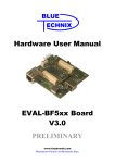
Hardware User Manual EVAL-BF5xx Board V3.1 (V3.0) PRELIMINARY www.tinyboards.com Maximum Power at Minimum Size Contact Bluetechnix Mechatronische Systeme GmbH Waidhausenstr. 3/19 A-1140 Vienna AUSTRIA/EUROPE [email protected] http://www.bluetechnix.com Document No.: 100-2205-3.1 Version 4 2006-12-30 Blackfin EVAL-BF5xx Hardware User Manual Table of Contents BLACKFIN Products................................................................................................................. 1 1 Introduction ......................................................................................................................... 3 1.1 Overview....................................................................................................................... 3 2 Functional Specification...................................................................................................... 5 3 PCB Placement and Mechanical Outline ............................................................................ 6 4 3.1 PCB Placement ............................................................................................................. 6 3.2 Mechanical Outline....................................................................................................... 7 Connector Description......................................................................................................... 8 4.1 P1 –SD-Card Connector ............................................................................................... 8 4.2 P2 – Power Connector .................................................................................................. 8 4.3 P4 – USB Connectors ................................................................................................... 8 4.4 P3 –RJ45 Ethernet Connector....................................................................................... 9 4.5 P5 – USB Connector..................................................................................................... 9 4.6 P6 – JTAG Connector................................................................................................... 9 4.7 P7 – CAN Connector .................................................................................................... 9 4.8 Expansion Connector Types ......................................................................................... 9 4.9 Px1 – Expansion Connector 1..................................................................................... 10 4.10 5 Px2 – Expansion Connector 2 ................................................................................. 13 Switches, Jumper and LED Description............................................................................ 17 5.1 S1 Ethernet Switch for CM-BF537E .......................................................................... 17 5.2 S5 Core Module Configuration................................................................................... 17 5.3 SW1 – UART Switch.................................................................................................. 17 5.4 JP1 - Power Supply Jumper ........................................................................................ 17 5.5 JP2 - Power Supply Jumper for RTC.......................................................................... 17 5.6 JP3 – UART Solder Pads............................................................................................ 18 5.7 Buttons ........................................................................................................................ 18 5.8 LEDs ........................................................................................................................... 18 6 Boot Mode Description ..................................................................................................... 19 7 Installation ......................................................................................................................... 21 8 Using the VDSP Flash Programming Tool ....................................................................... 25 8.1 Developing an Application ......................................................................................... 25 8.2 Overriding BLACKSheep Code ................................................................................. 25 Blackfin EVAL-BF5xx Hardware User Manual 9 Known Bugs ...................................................................................................................... 26 10 Revision History............................................................................................................. 27 A List of Figures and Tables.............................................................................................. 28 Blackfin EVAL-BF5xx Hardware User Manual Edition 2005-08 © Bluetechnix Mechatronische Systeme GmbH 2005 All Rights Reserved. The information herein is given to describe certain components and shall not be considered as a guarantee of characteristics. Terms of delivery and rights of technical change reserved. We hereby disclaim any warranties, including but not limited to warranties of noninfringement, regarding circuits, descriptions and charts stated herein. Bluetechnix makes and you receive no warranties or conditions, express, implied, statutory or in any communication with you. Bluetechnix specifically disclaims any implied warranty of merchantability or fitness for a particular purpose. Bluetechnix takes no liability for any damages and errors causing of the usage of this board. The user of this board is responsible by himself for the functionality of his application. He is allowed to use the board only if he has the qualification. More information is found in the General Terms and Conditions (AGB). Information For further information on technology, delivery terms and conditions and prices please contact Bluetechnix (http://www.bluetechnix.com). Warnings Due to technical requirements components may contain dangerous substances. The Core Boards and Development systems contain ESD (electrostatic discharge) sensitive devices. Electrostatic charges readily accumulate on the human body and equipment and can discharge without detection. Permanent damage may occur on devices subjected to high-energy discharges. Proper ESD precautions are recommended to avoid performance degradation or loss of functionality. Unused core boards and development boards should be stored in the protective shipping package. Blackfin EVAL-BF5xx Hardware User Manual Bluetechnix www.tinyboards.com Maximum Power at Minimum Size BLACKFIN Products CM-BF533: Blackfin Processor Module powered by Analog Devices single core ADSP-BF533 processor; up to 600MHz, 32MB RAM, 2MB Flash, 120 pin expansion connector and a size of 36.5x31.5mm CM-BF537U: Blackfin Processor Module powered by Analog Devices single core ADSP-BF537 processor; up to 600MHz, 32MB RAM, 4MB Flash, integrated USB 2.0 Device, 120 pin expansion connector and a size of 36.5x31.5mm CM-BF537E: Blackfin Processor Module powered by Analog Devices single core ADSP-BF537 processor; up to 600MHz, 32MB RAM, 4MB Flash, integrated TP10/100 Ethernet physical transceiver, 120 pin expansion connector and a size of 36.5x31.5mm CM-BF561: Blackfin Processor Module powered by Analog Devices dual core ADSP-BF561 processor; up to 2x 600MHz, 32MB RAM, 4MB Flash, 120 pin expansion connector and a size of 36.5x31.5mm TCM-BF537: Blackfin Processor Module powered by Analog Devices single core ADSP-BF537 processor; up to 500MHz, 32MB RAM, 8MB Flash, 28x28mm, 120 pin expansion connector, Ball Grid Array or Border Pads for reflow soldering, industrial temperature range -40°C to +85°C. EVAL-BF5xx: Low cost Blackfin processor Evaluation Board with one socket for any Bluetechnix Blackfin Core Module. Additional periphery is available, such as a SD-Card. EVAL-BF5xxDA: An EVAL-BF5xx including a Debug Agent. Low cost starter development system for Bluetechnix core Modules including VDSP++ Evaluation Software License. DEV-BF5xx: Blackfin Development Board with two sockets for any combination of Core Modules. Additional periphery is available, such as CF-Card, SDCard, DP-RAM, Ethernet, USB host and device, multi-port JTAG, connector for a LCD-TFT Display and connector for a digital camera system. EXT-Boards: The following Extender Boards are available: EXT-BF5xx-Audio, EXTBF5xx-Video, EXT-BF5xx-Camera, EXT-BF5xx-Experimental, EXTBF5xx-LVDS, EXP-BF5xx-ETH-USB, EXP-BF5xx-AD/DA. Additional boards based on customer request BLACKSheep: The BLACKSheep VDK is a multithreaded framework for the Analog Devices Blackfin processor family that includes driver support for a variety of hardware extensions. It is based on the real-time VDK kernel included within the VDSP++ development environment. Blackfin EVAL-BF5xx Hardware User Manual Page 1 Bluetechnix www.tinyboards.com Maximum Power at Minimum Size LabVIEW: LabVIEW embedded support for the CM-BF537E, CM-BF537U and TCM-BF537 Core Modules based on the BLACKSheep VDK driver Framework. Notes: For product development it is highly recommended that the developer purchase the DEV-BF5xx or EVAL-BF5xx (DA) Blackfin development board and the BLACKSheep VDK low level driver software for the on board peripherals. BLACKFIN Design Service Based on over three years Blackfin experience Bluetechnix offers development assistance as well as custom design services and software development. Blackfin EVAL-BF5xx Hardware User Manual Page 2 Bluetechnix www.tinyboards.com Maximum Power at Minimum Size 1 Introduction The EVAL-BF5xx Board is a low cost and lightweight evaluation platform for Bluetechnix Core Modules CM-BF533, CM-BF561, CM-BF534U, CM-BF537E, CM-BF537U and the upcoming TCM series of core modules. The small baseboard has all hardware necessary to test the performance of the core modules including a high-speed serial port directly connectable to a computers USB port, a digital video camera interface and a SD-Card mass storage device socket. 1.1 Overview The EVAL-BF5xx Board includes the following components: 60 Pin Expansion Connector B USB to UART JTAG SD-Card Connector CM-BF533 CM-BF534U CM-BF537E CM-BF537U CM-BF561 TCM-BF537 Core Modules CAN Connector (for CM-BF534U a. CM-BF537E/U) USB (for CM-BF534U and CM-BF537U) RJ-45 (for CM-BF537E) 60 Pin Expansion Connector A Figure 1-1: Overview of the EVAL-BF5xx Board 1 Core Module Slot o Supports all current Bluetechnix Blackfin based Core Modules USB o Supports up to 915kbps UART-USB conversion. o Emulates a standard COM port on the computer. JTAG o JTAG-Plug that supports all analog Devices JTAG Emulators. Blackfin EVAL-BF5xx Hardware User Manual Page 3 Bluetechnix www.tinyboards.com Maximum Power at Minimum Size Expansion Connector 1 o SPORT 0 o JTAG o UART o SPI o PPI-1 (Parallel Port Interface 1) o PFs (Programmable Flags) Expansion Connector 2 o Data Bus o Address Bus o Memory Control Signals o PPI-21 (Parallel Port Interface 2) o Power Supply 2nd USB Connector (optional) o Can only be used together with the CM-BF534U and CM-BF537U Core Module which has an on-board NETPLX 2272 USB2.0 Device Chip RJ-45 Ethernet Plug o Only in combination with the CM-BF537E module o Standard 10BASET/100BASET Ethernet connection 1 Only available when using the CM-BF561 Core Module Blackfin EVAL-BF5xx Hardware User Manual Page 4 Bluetechnix www.tinyboards.com Maximum Power at Minimum Size 2 Functional Specification Figure 2-1: Detailed Block Diagram Figure 2-1 shows a detailed block diagram of the EVAL-BF5xx Board. For powering the board the Power connector or the USB Device connector can be used. Please note that your USB Device connector may not be sufficient for powering all Core Modules or any Extension Board. The serial port of the Core Module can be routed directly to the USB Port (USB/UART Switch Position A towards the board edge) or to the UART Expansion Pads (USB/UART Switch Position B towards the Core Module). The two 60-pin expansion connectors bring all pins of the Core Module (Pin assignement in Section 2.2.3 and 2.2.4) directly to the expansion slot. An SD-Card connector mounted at the bottom of the board allows making use of file IO Functions delivered with the BLACKSheep Software. BLACKSheep supports SD-Cards and includes a FAT files systems as well as the most relevant File IO Functions (depending on the Software Version). The 2nd USB Device connector (colored in purple) can only be used with the CM-BF534U or the CM-BF537U Core Module which has an on-board USB V2.0 Device (NET2272 by PLXtechnology). The RJ-45 Ethernet connector (colored in purple) can only be used in combination with the CM-BF537E Core Module. Blackfin EVAL-BF5xx Hardware User Manual Page 5 Bluetechnix www.tinyboards.com Maximum Power at Minimum Size 3 PCB Placement and Mechanical Outline 3.1 PCB Placement Figure 3-1: Connector PCB Placement Blackfin EVAL-BF5xx Hardware User Manual Page 6 Bluetechnix www.tinyboards.com Maximum Power at Minimum Size 3.2 Mechanical Outline Figure 3-2: Mechanical Outline – Expansion Connector Placement Blackfin EVAL-BF5xx Hardware User Manual Page 7 Bluetechnix www.tinyboards.com Maximum Power at Minimum Size 4 Connector Description In the following the connectors shown in section 3.1 are described. 4.1 P1 –SD-Card Connector Pin No. 0 1 2 3 4 5 6 7 8 9 10 11 12 13 Signal (Core Module) NCS MOSI GND 3,3V SPICLK GND MISO PP11 WP GND GND Description (SD Card) DAT2 CD/DAT3 CMD VSS1 VDD CLK VSS2 DAT0 DAT1 CD WP GND GND Table 4-1: SD-Card Connector 4.2 P2 – Power Connector As a second power supply option, or if the 500mA provided by USB are not sufficient, P2 can be used as the main or as the secondary power connector. Both connectors P1 and P2 can be plugged into the evaluation board at the same time. Pin No. 1 2 3 Signal GND NC Vin (+4V Supply Description to +7V) Input Preferable 5V Table 4-2: Power Supply 4.3 P4 – USB Connectors P4 is a standard USB-B Device Connectors. From P4 the board may draw its power of up to 500mA at most. Without extension board this is enough power to run a CM-BF533 board @ 600MHz including a SD-Card. Anyway, this is not guaranteed for any Bluetechnix Blackfin Core Module. Blackfin EVAL-BF5xx Hardware User Manual Page 8 Bluetechnix www.tinyboards.com Maximum Power at Minimum Size 4.4 P3 –RJ45 Ethernet Connector Pin No. 1 2 3 4 5 6 7 8 Signal (Core Module) TX+ TXRX+ VA2.5V NC RXGND Description O O I PWR NC I PWR Table 4-3: Ethernet Connector 4.5 P5 – USB Connector P5 is a standard USB-B Device Connectors. The USB connector is used for the CM-BF537U. 4.6 P6 – JTAG Connector The JTAG connector is compliant to any Blackfin JTAG Emulator from Analog Devices. 4.7 P7 – CAN Connector Pin No. 1 2 Signal (Core Module) CANCAN+ Signal Type I/O I/O Table 4-4: CAN Connector 4.8 Expansion Connector Types The Expansion Connectors on the EVAL-BF5xx for a Stacked Height of 16mm are of the following type: Part Px1, Px2 Matching connector Manufacturer AMP (Stacked Height = 16mm) AMP Manufacturer Part Nr. 5-5179010-2 5179031-2 Table 4-5: DEV-board connector types The matching connector, which is used for building an extender board, can be ordered from Bluetechnix. Blackfin EVAL-BF5xx Hardware User Manual Page 9 Bluetechnix www.tinyboards.com Maximum Power at Minimum Size 4.9 Px1 – Expansion Connector 1 Pin 31 and 32 of the Px1 are Vin of P2. This is the input voltage of the connector P2 (see section 4.2). Pin 29 and 30 of the Px1 are VLDO. This is the voltage of the onboard LDO (Vin – Vdiode). Details are found in the schematics of the EVAL boards. CM-BF533 (inserted): PIN No Signal 1 3 5 7 9 11 13 15 17 19 21 23 25 27 29 31 33 35 37 39 41 43 45 47 49 51 53 55 57 59 RSCLK0 TSCLK0 RSCLK1 TSCLK1 3V3 PPI0 PF15 / PPI4 PF11 / PPI8 PF7/SPISEL7/PPI12 PF3/SPISEL3/PPI_FS3 TMR0 RX SCK GND VLDO Vin of P2 n.c. n.c. MISO PF0 / nSPISS PPI_CLK PF4/SPISEL4/PPI15 PF8 / PPI11 PF12 / PPI7 PPI3 GND DT1SEC DR1SEC DT0SEC DR0SEC Signal type I/O I/O I/O I/O PWR I/O I/O I/O I/O I/O I/O I I PWR PWR I/O I/O I/O I/O I/O I/O I/O PWR O I O I Pin No Signal 2 4 6 8 10 12 14 16 18 20 22 24 26 28 30 32 34 36 38 40 42 44 46 48 50 52 54 56 58 60 DR0PRI DT0PRI DR1PRI DT1PRI 3V3 PPI2 PF13 / PPI6 PF9 / PPI10 PF5/SPISEL5/PPI14 TMR1 / PPI_FS1 PF1 / SPISEL1 MOSI BMODE0 n.c. VLDO. Vin of P2 n.c. BMODE1 TX PF2 / SPISEL2 TMR2 / PPI_FS2 PF6/SPISEL6/PPI13 PF10 / PPI9 PF14 / PPI5 PPI1 GND TFS1 RFS1 TFS0 RFS0 Signal type I O I O PWR I/O I/O I/O I/O I/O I/O I/O I PWR I O I/O I/O I/O I/O I/O I/O PWR I/O I/O I/O I/O Table 4-6: Connector Px1 pin assignment for CM-BF533 Blackfin EVAL-BF5xx Hardware User Manual Page 10 Bluetechnix www.tinyboards.com Maximum Power at Minimum Size CM-BF537E (inserted): Pin No 1 3 5 7 9 11 13 15 17 19 21 23 25 27 29 31 33 35 37 39 41 43 45 47 49 51 53 55 57 59 Signal Signal type RSCLK0/TACLK2 I/O TSCLK0/TACLK1 I/O CLK_out O PF4/TMR5/SPI_CS6 I/O 3V3 PWR PG0/PPI1D0 I/O PG4/PPI1D4 I/O PG8/PPI1D8/DR1SEC I/O PG12/PPI1D12/RE1PRI I/O PPI1SY3/PF7/TMR2 I/O PPI1SY1/PF8/TMR0 I/O PF1/DMAR1/TACI1/Rx0 I/O PF13/SCK I/O GND PWR VLDO Vin of P2 PWR n.c. n.c. PF12/MISO I/O PF14/SPI_SS I/O PPI1Clk/PF15/TMRCLK I/O PG15/PPI1D15/DT1PRI I/O PG11/PPI1D11/RFS1 I/O PG7/PPI1D7 I/O PG3/PPI1D3 I/O GND PWR PF5/TMR4/SPI_CS5 O PF10/SPI_SC1 I DT0SEC/CANTX/SPICS7 O DR0SEC/TACI0/CANRX I Pin No 2 4 6 8 10 12 14 16 18 20 22 24 26 28 30 32 34 36 38 40 42 44 46 48 50 52 54 56 58 60 Signal Signal type DR0PRI/ TACLK4 I DT0PRI/SPI_CS2 O SDA I/O PF5/TMR4/SPI_CS5 I/O 3V3 PWR PG2/PPI1D2 I/O PG6/PPI1D6 I/O PG10/PPI1D10/RSCLK1 I/O PG14/PPI1D14/TFS1 I/O PPI1SY1/PF8/TMR0 I/O PF3/Tx1/TMR6/TACI6 I/O PF11/MOSI I/O BMODE0 I n.c. VLDO Vin of P2 PWR BMODE2 I BMODE1 I PF0/DMAR0/Tx0 O PF2/Rx1/TMR7 I/O PPI1Sy2/PF8/TMR1 I/O PG13/PPI1D13/TSCLK1 I/O PG9/PPI1D9/TD1SEC I/O PG5/PPI1D5 I/O PG1/PPI1D1 I/O GND PWR PF6/TMR3/SPI_CS4 I/O SCL I/O TFS0 I/O RFS0/TACLK3 I/O Table 4-7: Connector Px1 pin assignment for CM-BF537 TCM-BF537 (inserted) Pin No. 1 3 5 7 9 11 13 15 Signal RSCLK0/TACLK2 TSCLK0/TACLK1 PH15 / MIICRS PH7 / COL Vin 3V3 PG0/PPI1D0 PG4/PPI1D4 PG8/PPI1D8/DR1SEC Signa l type I/O I/O I/O I/O PWR I/O I/O I/O Blackfin EVAL-BF5xx Hardware User Manual Pin No. 2 4 6 8 10 12 14 16 Signal DR0PRI/ TACLK4 DT0PRI/SPI_SSEL2 SDA PH6/MIIPHYINT Vin 3V3 PG2/PPI1D2 PG6/PPI1D6 PG10/PPI1D10/RSCLK1 Signa l type I O I/O I/O PWR I/O I/O I/O Page 11 Bluetechnix www.tinyboards.com Maximum Power at Minimum Size 17 19 21 23 25 27 29 31 33 35 37 39 41 43 45 47 49 51 53 55 57 59 PG12/PPI1D12/RE1PRI PPI1SY3/PF7/TMR2 MDC PF1/DMAR1/TACI1/Rx0 PF13/SPI_SCK GND VLDO Vin of P2 n.c. MDIO PF12/SPI_MISO PF14/SPI_SS PPI1Clk/PF15/TMRCLK PG15/PPI1D15/DT1PRI PG11/PPI1D11/RFS1 PG7/PPI1D7 PG3/PPI1D3 GND PH5/MIITxCLK PF10/SPI_SSEL1 DT0SEC/CANTX/SPI_SS EL7 DR0SEC/TACI0/CANRX I/O I/O I/O I/O I/O PWR I/O I/O I/O I/O I/O I/O I/O PWR I/O I O 18 20 22 24 26 28 30 32 34 36 38 40 42 44 46 48 50 52 54 56 58 PG14/PPI1D14/TFS1 PPI1SY1/PF8/TMR0 PF3/Rx1/TMR6/TACI6 PF11/SPI_MOSI BMODE0 n.c VLDO Vin of P2 BMODE2 BMODE1 PF0/DMAR0/Tx0 PF2/Tx1/TMR7 PPI1Sy2/PF8/TMR1 PG13/PPI1D13/TSCLK1 PG9/PPI1D9/TD1SEC PG5/PPI1D5 PG1/PPI1D1 GND PF6/TMR3/SPI_SSEL4 SCL TFS0 I/O I/O I/O I/O I I I/O I/O I/O I/O I/O I/O I/O PWR I/O I/O I/O I 60 RFS0/TACLK3 I/O Table 4-8: Connector Px1 pin assignment for TCM-BF537 CM-BF561 (inserted): Pin No Signal 1 3 5 7 9 11 13 15 17 19 21 23 25 27 29 31 33 35 37 RSCLK0 / PF28 TSCLK0 / PF29 PF11(Clk_out optional) PF7/SPISEL7/TMR7 3V3 PPI1D0 PPI1D4 PPI1D8 / PF40 PPI1D12 / PF44 PPI1SYNC3 PF3 / SPICS2 RX / PF27 SCK ARDY VLDO Vin of P2 n.c. nABE1 MISO Signal type I/O I/O I/O I/O PWR I/O I/O I/O I/O I/O I/O I/O I/O I PWR O I/O Blackfin EVAL-BF5xx Hardware User Manual Pin No Signal 2 4 6 8 10 12 14 16 18 20 22 24 26 28 30 32 34 36 38 DR0PRI DT0PRI / PF18 PF9 PF5/SPISEL5/TMR5 3V3 PPI1D2 PPI1D6 PPI1D10 / PF42 PPI1D14 / PF46 PPI1SYNC1 / TMR8 PF1/SPISEL1/TMR1 MOSI nABE2 n.c. VLDO Vin of P2 nAMS3 nABE0 TX / PF26 Signal type I I/O I/O I/O PWR I/O I/O I/O I/O I/O I/O I/O O PWR O O I/O Page 12 Bluetechnix www.tinyboards.com Maximum Power at Minimum Size 39 41 43 45 47 49 51 53 55 57 59 PF0/SPISS/TMR0 PPI1CLK PPI1D15 / PF47 PPI1D11 / PF43 PPI1D7 PPI1D3 GND PF4/SPISEL4/TMR4 PF8 DT0SEC / PF17 DR0SEC / PF20 I/O I I/O I/O I/O I/O PWR I/O I/O O I 40 42 44 46 48 50 52 54 56 58 60 PF2/SPISEL2/TMR2 PPI1SYNC2 / TMR9 PPI1D13 / PF45 PPI1D9 / PF41 PPI1D5 PPI1D1 GND PF6/SPISEL6/TMR6 PF10 TFS0 / PF16 RFS0 / PF19 I/O I/O I/O I/O I/O I/O PWR I/O I/O I/O I/O Table 4-9: Connector Px1 pin assignment for CM-BF561 4.10 Px2 – Expansion Connector 2 CM-BF533 (inserted): Pin No Signal A1 A5 A9 A13 A17 ABE1 n.c. 1V8 n/BG GND nAWE D0 D4 D8 D12 D15 D11 D7 D3 nRESET nARE VDD-RTC Signal type O O O O O O O O PWR O I/O I/O I/O I/O I/O I/O I/O I/O I O PWR 1 3 5 7 9 11 13 15 17 19 21 23 25 27 29 31 33 35 37 39 41 43 45 47 49 51 53 2 4 6 8 10 12 14 16 18 20 22 24 26 28 30 32 34 36 38 40 42 44 nBR n.c. n.c. ABE0 A16 I O O 46 48 50 52 54 Blackfin EVAL-BF5xx Hardware User Manual Pin No Signal Signal type A3 O A7 O A11 O A15 O A19 O n.c. n.c. ADRY I CLK_Out 25MHz O nAMS3 O NMI I D2 I/O D6 I/O D10 I/O D14 I/O D13 I/O D9 I/O D5 I/O D1 I/O nAOE O nAMS2 O nBGH (at Slot B via O R205) n.c. n.c. n.c. A18 O A14 O Page 13 Bluetechnix www.tinyboards.com Maximum Power at Minimum Size 55 57 59 A12 A8 A4 O O O 56 58 60 A10 A6 A2 O O O Table 4-10: Connector Px2 pin assignment for CM-BF533 CM-BF537E (inserted): Pin No Signal A1 A5 A9 A13 A17 nABE1 GND RXnBG GND nAWE D0 D4 D8 D12 D15 D11 D7 D3 nReset nARE VDD-RTC Signal type O O O O O O I O PWR O I/O I/O I/O I/O I/O I/O I/O I/O I O PWR 1 3 5 7 9 11 13 15 17 19 21 23 25 27 29 31 33 35 37 39 41 43 45 47 49 51 53 55 57 59 Pin No 2 4 6 8 10 12 14 16 18 20 22 24 26 28 30 32 34 36 38 40 42 44 nBR TXLED_FD nABE0 A16 A12 A8 A4 I O O O O O O O 46 48 50 52 54 56 58 60 Signal Signal type A3 O A7 O A11 O A15 O A19 O LED_ACT O RX+ I ADRY I CLK_out O nAMS3 O NMI I D2 I/O D6 I/O D10 I/O D14 I/O D13 I/O D9 I/O D5 I/O D1 I/O nAOE O nAMS2 O nBGH (at Slot B via O R205) VA25 PWR TX+ O LED_SPEED O A18 O A14 O A10 O A6 O A2 O Table 4-11: Connector Px2 pin assignment for CM-BF537E TCM-BF537 (inserted) Pin No. 1 Signal A1 Signa l type O Blackfin EVAL-BF5xx Hardware User Manual Pin No. 2 Signal A3 Signa l type O Page 14 Bluetechnix www.tinyboards.com Maximum Power at Minimum Size 3 5 7 9 11 13 15 17 19 21 23 25 27 29 31 33 35 37 39 41 43 A5 A9 A13 A17 nABE1 / SDQM1 PH3/ETxD3 PH10/ERxD2 PH13/ERxCLK GND nAWE D0 D4 D8 D12 D15 D11 D7 D3 nReset nARE VDD-RTC O O O O O I/O I/O I/O PWR O I/O I/O I/O I/O I/O I/O I/O I/O I O PWR 4 6 8 10 12 14 16 18 20 22 24 26 28 30 32 34 36 38 40 42 44 45 47 49 51 53 55 57 59 PH12/ERxDV PH9/ERxD1 PH2/ETxD2 nABE0 / SDQM0 A16 A12 A8 A4 I/O I/O I/O O O O O O 46 48 50 52 54 56 58 60 A7 O A11 O A15 O A19 O PH1/ETxD1 I/O PH8/ERxD0 I/O ADRY I CLKBUF O nAMS3 O CLKOUT (SCLK) I D2 I/O D6 I/O D10 I/O D14 I/O D13 I/O D9 I/O D5 I/O D1 I/O nAOE O nAMS2 O PH14/ERXER (at Slot B I/O via R205) PH11/ERxD3 PWR PH4/ETxEN I/O PH0/ETxD0 I/O A18 O A14 O A10 O A6 O A2 O Table 4-12: Connector Px2 pin assignment for TCM-BF537 CM-BF561 (inserted): Pin No Signal 1 3 5 7 9 11 13 15 17 19 21 23 nABE3 A5 A9 A13 PPI2SYNC1 PPI2D1 PPI2D5 PPI2D9 / PF33 PPI2D13 / PF37 GND nAWE D0 Signal type O O O O I/O I/O I/O I/O I/O PWR O I/O Blackfin EVAL-BF5xx Hardware User Manual Pin No Signal 2 4 6 8 10 12 14 16 18 20 22 24 A3 A7 A11 A15 PPI2SYNC2 PPI2D3 PPI2D7 PPI2D11 / PF35 PPI2D15 / PF39 nAMST NMI0 D2 Signal type O O O O I/O I/O I/O I/O I/O O I I/O Page 15 Bluetechnix www.tinyboards.com Maximum Power at Minimum Size 25 27 29 31 33 35 37 39 41 43 D4 D8 D12 D15 D11 D7 D3 nRESET nARE n.c. I/O I/O I/O I/O I/O I/O I/O I O - 26 28 30 32 34 36 38 40 42 44 45 47 49 51 53 55 57 59 PPI2D12 / PF36 PPI2D8 / PF32 PPI2D4 PPI2D0 PPI2CLK A12 A8 A4 I/O I/O I/O I/O I O O O 46 48 50 52 54 56 58 60 D6 I/O D10 I/O D14 I/O D13 I/O D9 I/O D5 I/O D1 I/O nAOE O nAMS2 O PPI2D14 / PF38 (at Slot I/O B via R205) PPI2D10 / PF34 I/O PPI2D6 I/O PPI2D2 I/O PPI2SYNC3 I/O A14 O A10 O A6 O A2 O Table 4-13: Connector Px2 pin assignment for CM-BF561 Blackfin EVAL-BF5xx Hardware User Manual Page 16 Bluetechnix www.tinyboards.com Maximum Power at Minimum Size 5 Switches, Jumper and LED Description 5.1 S1 Ethernet Switch for CM-BF537E This 8 pin DIP switch enables the Ethernet connector. It is necessary for the Core Module CM-BF537E. Switch Settings Description CM-BF537E On Off 1 2 3 4 5 6 7 8 CM-BF533, CM-BF537U, TCM-BF537, CM-BF561 On Off 1 2 3 4 5 6 7 8 Table 5-1: Ethernet Switch 5.2 S5 Core Module Configuration Switch Settings S5 CM-BF533 and CM-BF561 Core Module inserted CM-BF534U, CM-BF537E, CM-BF537U and TCM-BF537 Table 5-2: Core Module Configuration 5.3 SW1 – UART Switch Move Sw1 to POSITION A to route the Core Modules RX and TX signals to USB Move Sw1 to Position B to route the Core Modules RX and TX signals to JP3 5.4 JP1 - Power Supply Jumper This jumper can be removed in order to insert an AMPERE METER for current measurement of the entire Core Module. 5.5 JP2 - Power Supply Jumper for RTC Enables power supply for RTC of the CM-BF53x. Blackfin EVAL-BF5xx Hardware User Manual Page 17 Bluetechnix www.tinyboards.com Maximum Power at Minimum Size 5.6 JP3 – UART Solder Pads Pin No. 1 2 3 4 Signal RxD Blackfin TxD Blackfin GND 3V3 Signal Type Input Core Module Output Core Module Regulated Power Table 5-3: UART Connector 5.7 Buttons The Button S2 is the main Reset Button of the Core Module. The Button S3 is a general-purpose input button. 5.8 LEDs The LED DS2 indicates that the board is powered. The LEDs DS1 and DS3 are connected to general-purpose IO pins. Core Module CM-BF533 CM-BF537U CM-BF537E TCM-BF537 CM-BF561 LED DS5 PF8 PG11 PG11 PG11 PF43 LED DS6 PF9 PG10 PG10 PG10 PF42 Button S3 PF5 PG14 PG14 PG14 PF46 Table 5-4: Core Module LEDs Ethernet LEDs DS2 DS3 DS4 Yellow Green Green Fullduplex Activity 100MB Speed LED Table 5-5: Ethernet LEDs Blackfin EVAL-BF5xx Hardware User Manual Page 18 Bluetechnix www.tinyboards.com Maximum Power at Minimum Size 6 Boot Mode Description Boot-settings for CM-BF561 (S4) If you are using a CM-BF561 set all switches of S4 OFF! Due to the limited number of pins on the two connectors, the CM-BF561 can only set its boot mode on the core module itself by changing the resistor settings. See the CM-BF561 Manual for further details. Boot-settings for CM-BF533 (S4) Switch Settings BMODE0,BMODE1 Boot Mode Description 0 Execute from16Bit ext. mem. Bypass ROM (Standard boot mode for uBoot) 1 Boot from 8Bit or 16Bit EEPROM/Flash (Standard boot mode for BLACKSheep) 2 Boot from SPI 8Bit 3 Boot from SPI 16Bit Table 6-1: Bootmode CM-BF533 Boot-settings for CM-BF537E, CM-BF537U and TCM-BF537 (S4) Switch Settings Boot BMODE0,BMODE1,BMODE2 Mode 0 Description Execute from16Bit ext. mem. Bypass ROM (Standard boot mode for uBoot) 1 Boot from 8Bit or 16Bit EEPROM/Flash (Standard boot mode for BLACKSheep) 2 Reserved 3 Boot from serial SPI Memory 4 Boot from SPI Host (slave mode) Blackfin EVAL-BF5xx Hardware User Manual Page 19 Bluetechnix www.tinyboards.com Maximum Power at Minimum Size 5 Boot from serial TWI memory 6 Boot from TWI host (slave mode) 7 Boot from UART host (slave mode) Table 6-2: Bootmode CM-BF534/537 Blackfin EVAL-BF5xx Hardware User Manual Page 20 Bluetechnix www.tinyboards.com Maximum Power at Minimum Size 7 Installation The installation guide is written for Windows (Windows 2000 and WinXP). However for connecting the USB device the driver for MAC and LINUX are available on the CD. In order to set up und test your EVAL-board the following steps can be done: 1. Make sure the Jumper JP1 is set and the Switch SW1 is in Position A as shown in the following picture: Figure 7-1: Overview of the EVAL-Board 2. If you want to use an SD-Card, insert the SD-Card in the appropriate slot at the bottom side of the board. Blackfin EVAL-BF5xx Hardware User Manual Page 21 Bluetechnix www.tinyboards.com Maximum Power at Minimum Size 3. Connect the EvalBoard via USB to the PC. The pre-flashed BLACKSheep starts and the LED mounted on the EVAL board starts blinking. On the PC usually the ‘Found New Hardware Wizard’ opens. If the wizard is asking you to look at the windows update site, select “No, not this time” Choose: “Install from a list or specific location”. The driver is located on your support CD. Blackfin EVAL-BF5xx Hardware User Manual Page 22 Bluetechnix www.tinyboards.com Maximum Power at Minimum Size This procedure has to be done twice, because at first the USB driver will be installed. Then the Hardware Wizard opens again, because the UART bridge driver has to be installed in addition using the same driver file. Please do the same again as described in this point. 4. Open the Windows device manager (Control Panel Æ System Æ Hardware) to see which COM port number has been assigned to the CP2101 UART-to-USB Chip. This number differs from computer to computer based on the already installed COM ports. (e.g. COM4) 5. Open a Terminal program like the HyperTerminal included in Windows operating systems and open the respective COM port with 115200 Baud, 8 Data-bits, No Parity and 1 Stop bit, disable the Hardware flow control. 6. Reset the Eval board (Press reset button S1). After this you will see the BLACKSheep boot-screen showing up. If you disconnect the device, you have to reconnect. Blackfin EVAL-BF5xx Hardware User Manual Page 23 Bluetechnix www.tinyboards.com Maximum Power at Minimum Size This shows a sample boot screen. Depending on the current software version, you might get different boot messages. 7. You can find a simple hello world program on your support CD or at the download section of the product homepage. To start the sample program, type “xmr UART” on your terminal program, then (Transfer Æ Send file) select the appropriate file “UART.ldr” depending on your Core Module, choose protocol “Xmodem” and send. After the download has finished type “exec UART” for executing the sample program. 8. Press reset to return to the BLACKSheep command line. Blackfin EVAL-BF5xx Hardware User Manual Page 24 Bluetechnix www.tinyboards.com Maximum Power at Minimum Size 8 Using the VDSP Flash Programming Tool 8.1 Developing an Application If you are developing your own projects with the VDSP++ development tools including the JTAG provided by Analog Devices you can use the flash programming tool included in the VDSP++ environment in order to flash your program on the core module. As flash driver you have to load the flash driver located on your EVAL board support CD (BF533EZFlasher.dxe). 8.2 Overriding BLACKSheep Code If you overwrite intentionally or unintended the section in the flash containing the BLACKSheep code, you need a JTAG device and the VDSP++ flash tool to reprogram the flash. Flashing the file BLACKSheep53x.ldr located on the CD, reinstalls the BLACKSheep code. Blackfin EVAL-BF5xx Hardware User Manual Page 25 Bluetechnix www.tinyboards.com Maximum Power at Minimum Size 9 Known Bugs Blackfin EVAL-BF5xx Hardware User Manual Page 26 Bluetechnix www.tinyboards.com Maximum Power at Minimum Size 10 Revision History 2006 12 30 USB Power Supply Update and Page Numbering 2006 10 02 Board Version changed to 3.1 2006 05 16 Ethernet Configuration 2006 03 03 Updated LED table 2006 02 28 Preliminary Version 3.0 2006 01 29 Update to Version 3.0 2005 12 19 Merging Getting Started with Hardware User Manual 2005 09 28 Release Version No. 2.0.1, board prepared for Ethernet and USB2.0 2005 02-08 Release Version No. 1.0 2004 12 20 Beta Version of the Document Blackfin EVAL-BF5xx Hardware User Manual Page 27 Bluetechnix www.tinyboards.com Maximum Power at Minimum Size A List of Figures and Tables Figures: Figure 1-1: Overview of the EVAL-BF5xx Board .................................................................... 3 Figure 2-1: Detailed Block Diagram.......................................................................................... 5 Figure 3-1: Connector PCB Placement ...................................................................................... 6 Figure 3-2: Mechanical Outline – Expansion Connector Placement ......................................... 7 Figure 7-1: Overview of the EVAL-Board .............................................................................. 21 Tables: Table 4-1: SD-Card Connector .................................................................................................. 8 Table 4-2: Power Supply............................................................................................................ 8 Table 4-3: Ethernet Connector ................................................................................................... 9 Table 4-4: CAN Connector ........................................................................................................ 9 Table 4-5: DEV-board connector types ..................................................................................... 9 Table 4-6: Connector Px1 pin assignment for CM-BF533 ...................................................... 10 Table 4-7: Connector Px1 pin assignment for CM-BF537 ...................................................... 11 Table 4-8: Connector Px1 pin assignment for TCM-BF537.................................................... 12 Table 4-9: Connector Px1 pin assignment for CM-BF561 ...................................................... 13 Table 4-10: Connector Px2 pin assignment for CM-BF533 .................................................... 14 Table 4-11: Connector Px2 pin assignment for CM-BF537E................................................. 14 Table 4-12: Connector Px2 pin assignment for TCM-BF537.................................................. 15 Table 4-13: Connector Px2 pin assignment for CM-BF561 .................................................... 16 Table 5-1: Ethernet Switch....................................................................................................... 17 Table 5-2: Core Module Configuration.................................................................................... 17 Table 5-3: UART Connector.................................................................................................... 18 Table 5-4: Core Module LEDs................................................................................................. 18 Table 5-5: Ethernet LEDs ........................................................................................................ 18 Table 6-1: Bootmode CM-BF533 ............................................................................................ 19 Table 6-2: Bootmode CM-BF534/537 ..................................................................................... 20 Blackfin EVAL-BF5xx Hardware User Manual Page 28