1
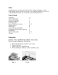
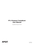
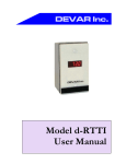
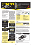
/ Marley Ultra Low-Noise Fan /
User Manual 07-1126
Contents
General Information....................................................................... 4
Installation..................................................................................... 5
Operation..................................................................................... 11
Maintenance............................................................................... 13
Parts List..................................................................................... 16
Trouble Shooting......................................................................... 17
3
General Information
Description
The Marley Ultra Low-Noise series of fans represent the top in the
new generation of super low noise fans—the FRP blades have been
developed to meet the most stringent noise limitations. The fans
permit variable pitch adjustment at standstill and feature a simplified
design. Each blade is fixed to the hub with two bolted aluminum
pillow blocks.
Balancing
When the rotor is dispatched in assembled form, each unit is dynamically balanced within a degree of G = 6.3 in accordance with
ISO 1940/1.
When the fan is dispatched disassembled, the hub is dynamically
balanced and the blades are statically balanced so that the reassembled unit correspond to a degree of G = 6.3 in accordance with
ISO 1940/1. In this case, the blades have the same static moment,
so that they can be positioned in any order on the hub; the blades
of the same supply, are interchangeable.
Storage
Upon unloading the fan, inspect it for any damage. If damage occurred, file a claim immediately against the carrier and mark the bill
of loading accordingly.
After the fan delivery, check the full compliance between order and
delivered goods. Shortages or inconformities have to be reported
within two weeks from receipt of shipment at destination.
If not installed immediately, it is recommended to store the fan in
a dry and shaded area, and do not put any heavy materials of any
kind upon the blades. For long-term storage, it is necessary to check
the condition of the corrosion preventive coating on all machined
surfaces.
4
Installation
Rotation and Flow Direction
The rotation direction is correct when the airflow moves from the
convex back (suction surface) of the blade, to the concave side
(pressure surface). Figure 1 shows the conventional clockwise direction of rotation and normal direction of airflow as viewed from
the discharge face of the rotor.
Flow Direction
Flow Direction
Figure 1
Installation Instructions
1––Remove blade pillow block and fasteners 4, 5, 6, 7, 15 from the
hub disk, one set a time (Figure 2).
2––If the hub has not been supplied already assembled to the flange,
install the coupling flange 2 on the disk 3, complying with torque
settings, bolt orientation, tightening order, and pins as shown in the
table following Figure 2.
5
Installation
10B
9
10A
3
7
5
1
2
Figure 2
8
6
4
6
10
Installation
Torque hub assembly bolts 11 according to the following table:
Fan Diameter Flange Type
inches
84" to 96"
108" to 168"
Type 115
Type 190
Bolt Type
Bolt Torque
N·m
ft·lb
M16 cl. 8.8
230
169
M16 cl. A4-70
126
93
M16 cl. A4-80
168
124
M20 cl. 8.8
447
329
M20 cl. A4-70
246
181
M20 cl. A4-80
328
241
3––Hub into driveshaft installation (Figure 2).
• As for the hub with cylindrical bore, the hub is bored to attach
directly to the drive shaft.
Coat the output drive shaft with a thin layer of silicon grease.
If a space ring 10A is supplied, drive it into the drive shaft until it
comes in contact with the drive shaft shoulder.
Drive the hub with cylindrical bore into the drive shaft until it comes
in contact with the drive shaft shoulder (or space ring shoulder if
supplied).
Warning
Never power the drive shaft with special washer 16 and the retaining bolt 17 missing or loose.
• As for the hub with tapered bushing hole, be sure drive shaft,
bushing and hub bore are not greased. Slide the bushing into the
drive shaft to your design position.
Position the hub core over the bushing taper; insert bushing screws
through the bushing flange into the threaded hole in the hub coupling;
torque bushing screws according to the following table:
Bushing Type
Screw Torque
N·m
ft·lb
Q1 and Q2
40
29
R1 and R2
40
29
7
Installation
Caution
Warning
The drive shaft end must remain recessed at least 1⁄32" in the hub
bore to prevent dangerous rotor vertical translation once retaining
bolt 16 has been tightened to the shaft end.
Never power the drive shaft with bushing bolts not torqued or
bushing improperly positioned.
4––Install the blade.
Sandwich the blade shank between the pillow blocks 4 and 5, ensuring both the pins 7 are in proper position (Figure 2).
Fit pillow blocks 4 and 5, pins 7, pillow block plate 6, blade and
pillow block fasteners 15 on hub disk as shown in previous Figure
3 without tightening bolts.
Rotate fan to check tip clearance is in accordance with the specified
value (tip clearance ratio x/D, where x = the distance from the blade
tip to the fan ring and D = the rotor diameter). The gap between
blade tip and fan ring must be measured along blade axis.
Tighten the pillow block bolts 15, to hold the blade in extended
position, leaving enough clearance to allow blade rotation on its
own axis for pitch setting.
5––Setting blade pitch.
The pitch angle of each blade has to be set at the A° value specified
in the rotor identification plate with a 0.5° maximum tolerance: in
order to set the pitch, the quotes shown in following Figure 3 must
be observed; note these quotes are shown on the fan data sheet, and
are specific for each diameter of the Marley Ultra Low-Noise fan.
8
Installation
G X øH
R
T
Z
V
S
K
D
U
øF
øE
øC
Figure 3
FAN DIAMTER (A)
Rotate the blade on its axis until the required pitch angle is obtained.
Check there is no gap between each blade shaft shoulder and corresponding pillow block.
Torque pillow block bolts 15 according to the following tables,
complying with bolt orientation and tightening order as shown in
Figure 4.
Figure 4
1
3
4
2
4 Bolt Pillow Block Tightening Order
6––Repeat for each blade steps described in points 4 and 5. Before
starting the pitch angle setting procedure, turn the fan till the blade
to be set is at the same point in the fan ring where previous pitch
angle was set.
In order to determine the torque setting of standard bolts 15, with
the 8.8 stamping, search in the following table the bolt type set for
the diameter of the fan in object.
9
Installation
Fan Diameter
inches
Note
Bolt 15
Bolt Torque
N·m
ft·lb
84" to 96"
M18
282.5
208
108" to 120"
M20
400.3
294
132" to 144"
M24
679.8
500
The screw class information is shown in the fan documentation part list.
Stainless steel bolts 15 with the A4-80 stamping:
Fan Diameter
inches
Note
10
Bolt 15
Bolt Torque
N·m
ft·lb
84" to 96"
M18
175.6
129
108" to 120"
M20
246.2
181
132" to 144"
M24
425.7
313
In the case of a structure equipped with multiple fans, before
setting the pitch angle to all the fans, set the pitch on one fan
only and follow the instructions for operation starting on page
11.
Operation
Prior to Start-Up
1––Make sure all the pillow blocks are fixed to the hub boss—if any
movement of the blocks is detected, do not operate the fan and
check the torque of bolts 15.
2––Rotate fan to check tip clearance is in accordance with the specified value (tip clearance ratio x/D, where x = the distance from the
blade tip to the fan ring and D = the rotor diameter). The gap between
blade tip and fan ring must be measured along blade axis.
3––Check gear box oil level or belt tension to be as indicated by
the manufacturer.
4––Remove all tools from the area.
5––Connect motor to power supply.
6––Start fan for a few seconds, and then switch it off. While the fan
is still turning, check that the direction of the blade rotation is correct (see Rotation and Flow Direction).
Post Start-Up
1––Check power absorption: if excessive, reduce the blade pitch
angle until the desired power is achieved (set the new pitch on all
the fans of a same structure); if lower than predicted, increase the
blade pitch angle until the desired power is achieved (set the new
pitch angle on all the fans of a same structure).
Note
Power absorption varies in inverse proportion to the air temperature.
2––Check the vibrations level in the position shown in Figure 5.
Do not exceed the most restrictive amplitude values between the
limits imposed by the normative of the structure where the fan is
installed and the limits imposed by the VDI 2056 normative. In this
case, shut down the unit and trace the cause of such excessive
vibration by referring to section Possible Causes of Vibration in the
following section.
11
Operation
Figure 5
3––After the rotor has been running for one hour, check the torque
of the hub screws 15.
4––Repeat the check of screws 15 after 24 hours from start-up.
12
Maintenance
Maintenance and Operation
1––Inspect the overall fan condition periodically.
Inspection intervals depend on fan operating conditions and may
vary from a minimum of 2 weeks to a maximum of 6 months.
The following components should be specifically inspected when
inspecting the overall fan conditions:
- Screw torque.
- Fasteners corrosion.
- General condition of blade surface.
2––Ice formation on the blades of operating fans must be strictly
avoided.
3––If ice has formed on a stationary fan, it must be removed prior
to start-up to avoid damaging the blades. Snow formed on a stationary fan must be periodically removed, according to the snow
accumulation itself.
4––Turn off 2-speed motor for at least 30 seconds before switching
to low speed.
5––Stop the unit completely before reversing the fan direction.
6––Check the vibrations level in the position shown in Figure 5 at
regular intervals.
The vibration level must not exceed the most restrictive amplitude
values between the limits imposed by the normative of the structure
where the fan is installed and the limits imposed by the VDI 2056
normative. In this case, shut down the unit and trace the cause of
such excessive vibration by referring to page 14.
It is advisable to keep a record of the readings taken on each occasion for comparison. Always take readings at the same positions
and in the same manner. Observe the safety precautions insuring
power supply is turned off. The fan vibration levels constitute an
invaluable indication of the state of the plant and should be monitored frequently (e.g. monthly).
Temperature Range
This series of fans are designed to operate at these temperatures.
Minimum is -20ºC (-4ºF)
Maximum is +82ºC (+180ºF)
13
Maintenance
Possible Causes of Vibration
The actual causes of vibration may change considerably. Some of
the most common are as follows.
1–– Unbalance of one or more blades: the vibration caused by blade
imbalance occurs on the tip path plane with a frequency equal to
the fan RPM and at an amplitude which is dependent on the degree
of imbalance and the square of the rotational speed.
2––Blade pitch angle not included in the ± 0.5° tolerance: this condition causes vibration outside the tip path plane at a frequency
equal to the fan RPM and at an amplitude which is dependent on
the square of the rotational speed.
3–– Blades too close to supports (periodic aerodynamic turbulence):
this condition is characterized by vibration outside the tip path plane
at a frequency equal to the product of the number of fan blades and
RPM. The amplitude depends upon the extent of the aerodynamic
turbulence.
4––Resonance between one of the possible forcing frequencies of
the fan and one or more of the vibration modes of the structure on
which it is installed. The main forcing frequencies generated by the
fan, normally correspond to the following frequencies:
- Fan RPM
- The product of fan RPM and the number of blades
- The product of fan RPM and the number of structural
supports capable of generating aerodynamic turbulence
(if they are arranged in an axial-geometric fashion).
5–– Vibration transmitted by the structure on which the fan is installed:
the frequencies of such vibration depend on both the external forcing
frequencies and the resonant frequencies of the structure.
6––Resonance of the blades with one of the possible forcing frequencies; in the vast majority of cases the vibration occurs outside
of the tip path plane.
7––Misalignment of the drive shaft: this generates vibration with a
frequency that is once or twice the RPM.
8––Loosening of blade and/or speed reducer fixing bolts. The behavior
of the rotor under these circumstances is totally unpredictable, as
it depends upon the extent and location of the loosening.
14
Maintenance
9––Worn output shaft bearing: this condition generates vibration on
the tip path plane at a frequency equal to the rotor RPM.
10––The fan and/of the structure bolts are not tightened: in this case
all the bolts have to be tightened.
11––The draining holes of the blades are obstructed: they have to
be opened.
Note
The amplitude of the fan vibrations is determined by the rigidity
of its support. Vibration that would not be critical to a fan supported by a sufficiently rigid structure is amplified by an overly
flexible support. This support rigidity may also cause unexpected
variations in the resonant frequencies of the blades.
15
Parts List
Item
16
Standard
Protection
1
Blade
FRP
––
2
Coupling Flange
Steel
Epoxy Paint
3
Hub Disk
Steel
Epoxy Paint
4
Lower Pillow Block
Aluminum
––
5
Upper Pillow Block
Aluminum
––
6
Pillow Block Plate
Steel
Epoxy Paint
7
Pins
Steel
Zinc Plated
8
Coupling Flange Washer
Steel - R40
HDG
9
Coupling Flange Lock Washer
Steel - R40
HDG
10
Note
Standard
Material
Description
Figure 6
Coupling Flange Nut
Steel - 8.8 class
HDG
10A
Space Ring (if needed)
Steel
Zinc Plated
10B
Taper Bushing (if required)
Malleable Cast Iron
Burnished
11
Coupling Flange Bolt
Steel - 8.8 class
HDG
12
Pillow Block Washer
Steel - R40
HDG
13
Pillow Block Lock Washer
Steel - R40
HDG
14
Pillow Block Nut
Steel - 8.8 class
HDG
15
Pillow Block Bolt
Steel - 8.8 class
HDG
16
Screw (not included)
––
––
17
Washer (not included)
––
––
For special applications, materials and protective coatings
could be different. In this case, make reference to the fan documentation.
Parts List
11
8
15
12
6
2
5
1
16
17 16
4
7
3
12
13
14
8
9
10
Figure 6
10B
10A
17
Troubleshooting
Trouble
Cause
Remedy
System congestion.
Clean the entire system.
Check the real obstacles area and the inlet shape towards
the original design.
Obstacles to the air flow.
In dry-coolers the minimum free height of the inlet area has
to be 1 time the fan diameter at least; this height has to be
higher in case of multiple units in line.
Static pressure higher than the specified
one.
Increase blade pitch angle (till 3º after checking the data
sheet selection.
Pitch angle lowered by blade rotation
(e.g. screw (15) not tightened at the right
torque).
Set the right pitch angle and refer to the operation manual
to set the right torque of screws and bolts.
Temperature higher than the design.
Increase blade pitch angle (till 3º after checking the data
sheet selection.
Temperature lower than the design.
Decrease blade pitch angle (till 3º after checking the data
sheet selection.
Static pressure lower than the design.
Decrease blade pitch angle (till 3º after checking the data
sheet selection.
Screws and bolts of the fan and/or the
structure loosened.
Torque all screws and bolts.
Fan not centered.
Center the fan.
Tip clearance too small.
Increase the fan ring diameter.
Unbalance of one or more blades.
Contact SPX Cooling.
Blade pitch angle not included in the 0.5º
tolerance.
Set right blade pitch angle.
Blades too close to supports (periodic aerodynamic turbulence).
Contact SPX Cooling.
Low air flow
Low power absorption
High power absorption
Rubbing between the
blades and the fan ring
Resonance between one of the possible
forcing frequencies of the fan and one or
Contact SPX Cooling.
more of the vibration modes of the structure
on which it is installed.
High vibration level
Vibration transmitted by the structure on
which the fan is installed.
Contact SPX Cooling.
Resonance of the blades with one of the
Contact SPX Cooling.
possible forcing frequencies.
Misalignment of the drive shaft.
Realign of the drive shaft.
Worn output shaft bearing.
Contact the supplier.
The fan and/or the structure bolts are not
Tighten screws and bolts at the right torque.
tightened.
The draining holes of the blades are obstructed.
18
Open the draining holes.
7401 WEST 129 STREET | OVERLAND PARK, KANSAS 66213 UNITED STATES | 913 664 7400 | [email protected] | spxcooling.com
In the interest of technological progress, all products are subject to design and/or material change without notice.
©2009 SPX Cooling Technologies, Inc. | Printed in USA
M07-1126