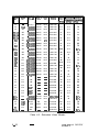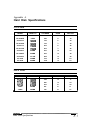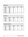
1
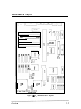
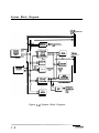
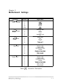
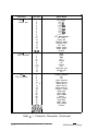
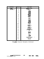
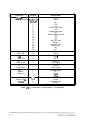
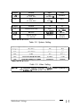
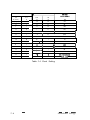
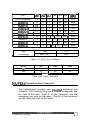
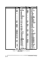
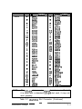
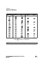
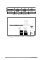
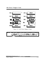
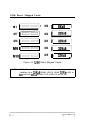
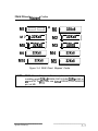
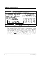
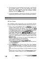
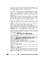
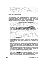
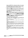
486~VAC-V
MAIN BOARD
USER’S MANUAL
DOC. No. : 12529
REVISION : Al
DATE
: November 1993
Table of Contents
Chapter 1 Overview
Specifications
Mot
herboard
System
Block
. . . . . . . . . . . . . . . . . . . . . . 1-I
Layout
..................
Diagram
1-3
. . . . . . . . . . . . . . . . . 1-4
Chapter 2 Motherboard Settings
Connector Description ................. 2-l
System Setting ..................... 2-5
Video Setting ...................... 2-5
Clock Setting ...................... 2-6
CPU Type Selection .................. 2-7
Cache Selection .................... 2-7
ISANESA Expansion Slot Connector ........ 2-7
Chapter 3 System Memory
Memory Configuration ................. 3-l
Cache Configuration Size ............... 3-2
64K Direct Mapped Cache
.............. 3-3
128K Direct Mapped Cache .............. 3-4
256K Direct Mapped Cache .............. 3-5
i
Chapter 4 Award BIOS Setup
System
Setup
. . . . . . . . . . . . . . . . . . . . . .
4-l
Standard CMOS Setup ............... 4-2
BIOS and Chipset Features Setup ......... 4-3
Load Setup Default ................. 4-4
Load BIOS Default
................. 4-4
Password Setting .................. 4-4
Exiting Setup ..................... 4-5
Chapter 5 AMI BIOS Setup
System Setup. ..................... 5-I
................ 5-2
Standard CMOS Setup
Advanced CMOS Setup ............ _. ... 5-3
Write to CMOS and Exit ................ 5-4
Chapter 6 VGA Utility and Drivers
CLMode ......................... 6-3
Using CLMode’s Menu-driven Interface ...... 6-3
Available Video Modes ............... 6-3
Getting Help ..................... 6-4
Exiting the CLMode ................. 6-4
Using CLMode’s Command Line Options ..... 6-5
Software Drivers .................... 6-5
Windows 3.013.1 ................... 6-5
AutoCAD 9/I O/l l/1 2
GEM3.0
................ 6-6
....................... 6-7
Lotus l-2-3 2.x .................... 6-9
Lotus l-2-3 3.0/3.1
................
6-10
MS Word 5.0 .................... 6-11
OSl2R.2.0 ..................... 6-12
~~_u______.I__I_-----.---~-~-~~.~.-ii
Ventura Publisher 2.x/3.0 ............. 6-l 6
WordPerfect 5.0/5.1/6.0
............. 6-17
WordStar 5.517.0 2000 V. 3.5
.......... 6-l 8
Appendix A Hard Disk Specifications ............. A - l
List of Figures
Figure l-l. Motherboard Layout ........... 1-3
Figure 1-2. System Block Diagram .......... l - 4
Figure 3-l. Cache Bank Location on Motherboard . 3-2
Figure 3-l. 64K Direct Mapped Cache ........ 3-3
Figure 3-2. 128K Direct Mapped Cache ....... 3-4
Figure 3-3. 256K Direct Mapped Cache ....... 3-5
List of Tables
Table 2-l. Connector Description
.......... 2 - l
Table 2-2. System Setting ............... 2-5
Table 2-3. Video Setting ................ 2-5
Table 2-4. Clock Setting ................ 2-6
Table 2-5. CPU Type Selection ............ 2-7
Table 2-6. Cache Selection .............. 2-7
Table 2-7. ISANESA Slot Connector
Table 3-l. Memory Configuration
........ 2-8
.......... 3-l
Table 3-2. Cache Configuration Size
........ 3-2
Table 6-l. Standard Video Modes ......... 6-19
Table 6-2. Extended Video Modes ......... 6-20
...
111
Chapter 1
Overview
The 486~VAC-V is a high-performance All-in-One
motherboard offering outstanding features and performance
for building advanced personal computers or workstations.
Based on ISANESA BUS architecture, this multi-function
board includes built-in IDE and FDC interfaces. The on-board
Cirrus Logic VGA controller is directly linked to the Local BUS,
providing enhanced video performance and Windows
acceleration functions.
Specifications
The 486-VAC-V motherboard comes with the following
features:
0
0
0
0
Intel 80486SWDWDX2TM and Intel 80487SXTM CPU in PQFP
and PGA packages.
VIA VT82C481m and VT82C495m PC/AT Chipset.
Supports O/64/1 28/256K direct-mapped write-back cache
memory.
Supports 1 to 64MB DRAM memory; page mode DRAM
operation.
0
Shadow RAM.
0
IMB BIOS.
0
One 16.bit ISA expansion slot.
0
One VESA expansion slot.
0
Real time clock/calendar.
0
Built-in SMC651m for IDE HDD and FDD interface.
Overview
l
Built-in PDC20230m local IDE interface.
l
Two serial ports and one parallel port.
l
PS/2 mouse and keyboard connector.
l
l
Built-in Cirrus GD5426TM or GD5428m VGA with 1 or 2MB
Video RAM on board.
LPM-size board.
-Y--u_____________________________I__________--~
Y-5
Overview
Motherboard Layout
JK3
,-
BANK3
SIMM4
BANK2
SIMM3
BANK1
SIMM2
BANK0
SIMM 1
1
El
37c651
J15
1
il
El-2:
7
J24
d
d
J23
r-------l
000
J22 J21 J20
Figure I - 7. Motherboard Layout
J16
El
System Block Diagram
112 n
VES8’Expansion
G,,5426 II, VGA Connector
85 I4A Connector
I
I
SYSTEM DATA BUS SD
64 SD
Local IDE
Figure I-2. System Block Diagram
Chapter 2
Motherboard Settings
Pin Out
Signal Name
CNl Power connector
1
2
3
4
5-8
9
10-12
Power go
+5v
+12v
-12v
Ground
-5v
+5v
CN2 PS/2 Keyboard
1
2
3
4
5
6
Keyboard data
NC
Ground
vcc
Keyboard clock
NC
CN3 PS/2 Mouse
1
2
3
4
5
6
Mouse data
NC
Ground
vcc
Mouse clock
Ground
CN4 Serial Port1
1
2
3
4
5
6
7
8
9
Data carrier detect
Receive data
Transmit data
Data transmit ready
Ground
Ready to receive data
Request to send data
Clear to send
Ring indicator
1
2
3
4
5
6
7
8
9
Data carrier detect
Receive data
Transmit data
Data transmit ready
Ground
Ready to receive data
Request to send data
Clear to send
Ring indicator
Connector
CN5 Serial Port 2
.__-_-_
Table 2- I, Connector Description
Connector
CN6 Parallel port
Pin Out
Signal Name
1
2
3
4
5
6
7
8
9
10
12
13
14
15
16
17
18-25
LPT strobe.
LPT DO
LPT Dl
LPT 02
LPT D3
LPT 04
LPT D5
LPT DS
LPT D7
LPT acknowledge
LPT busy
Paper end
Selected status
Auto line feed
LPT error
Initiate printer
Select printer
Ground
1
2
3
4
5-8
9
10
1 l-12
13
14
15
Red
Green
Blue
NC
Ground
NC
Ground
NC
Horizontal sync
Vertical sync
NC
11
CN7 VGA Connector
CN8 FDD Connector
2
4
6
8
10
1 2 ’
14
16
18
20
22
24
26
28
30
32
34
1,3,5,7,9,11,
13,15,17,19,
21,23,25,27,
29,31,33
Density selection
NC
NC
Index detection
Select motor A
Select drive B
Select drive A
Select motor B
Direction control
Step pulse
Write data
Write enable
Track 0
Write protect
Read data
Head select
Disk change
Ground
c
Table 2- I. Connector Description (Continued)
l.~..-----LY...
2-2
Motherboard Settings
Connector
CN9 IDE Connector
Pin Out
1
2
3
4
5
6
7
8
9
10
11
12
13
14
15
16
17
18
19
20-21
22
23
24
25
26
27
28
29
30
31
32
33
34
35
36
37
38
39
40
Signal Name
Reset
hard disk
Ground
HDD7
HOD8
HDD6
HDD9
HDDS
HDDlO
HDD4
HDDll
HDD3
HDD12
HDD2
HDD13
HDDl
HDD14
HDD6
HDD15
Ground
NC
Ground
HD I/O write
Ground
HD I/O read
Ground
IOCHRDY
HD address latch
NC
Ground
IRQ14
IOCS16
HD Al
NC
HD A0
HDA2
HD chip select 0
HD chip select 1
HD active
Ground
Table 2- 1. Connector Description (Continued)
Motherboard Settings
2-3
Connector
Signal Name
Pin Out
CNlO 1
8514A Connector 2,4,6,16,18,
20,22,25
3
5
7
8
9
10
11
12
13
14
15
17
19
21
23
24
26
VP0
Ground
.
VP1
VP2
VP3
Enable video data
VP4
Enable sync signal
VP5
Enable video dot clock
VP6
NC
VP7
Video dot clock
Banking
Horizontal sync
Vertical sync
NC
NC
J13
HDD LED
1
2
HDD Signal
Ground
J20
Turbo LED
1
2
LED LED +
J21
Turbo Switch
1
2
Ground
Turbo signal
J22
Reset Switch
1
2
Ground
Reset signal
J23
Speaker
Connector
1
2
3
4
Speaker signal
NC
Ground
J24
Power LED &
1,2
3
4
5
Key lock
.
vcc
Power LED
Ground
Keyboard clock
Ground
Table 2- 1. Connector Description (Continued)
Jumper
Function
Open
Close
JQ
IOCHRDY
(for Hard Disk)
No
IOCHRDY #
IOCHRDY
J16
BALE
(for Hard Disk)
No
BALE #
BALE
Function
1-2
2-3
Software RTC Clear
Clear
(For AWARD)
( For AM)
J15
A20 Gate
FastA20#
KB A20
JK3
Address Decode
(for WEITEK)
Normal #
WEITEK
Interface
r Jumper
J7
Clear
TABLE NOTE: # Default
Table 2-2. System Setting
TABLE NOTE: # Default
Table 2-3. Video Setting
To upgrade display memory to ZMB, install 8 pieces of
DIP 44256-70 DRAM at Ml 1 to M18.
Motherboard Settings
1-2
0 (short)
3-4
0
1 (open)
0
0
0
32
0
1
0
0
40
50
1
1
0
0
0
0
1
0
1
0
1
II
0
II
66.6
0
1
1
III
0
II
66.6
II
0
II
Test
80
1
1
1
0
0
0
1
0
0
0
1
1
1
0
0
0
1
1
0
1
~__
1
-
1
50
0
1
1
1
33.3(Default)
1
1
1
1
PW_DN
*
I
1
12
1
16
1
I
25
1
I
I
I
I
I
40
Table 2-4. Clock Setting
2-6
Motherboard Settings
I
I
I
I
I
I
I
I
I
I
CPU
JKl
JK2
JCI
JC2
JC3
JC4
OSCl
wr)
804860X-33 (Default)
2-3
2-3
l-2
1-2
ON
ON
33.33
1-2
1-2
l-2
l-2
ON
ON
50.00
l-2
1-2
1-2
1-2
ON
ON
40.00
80486DX2-66
2-3
2-3
l-2
l-2
ON
ON
33.33
80486DX2-50
l-2
1-2
1-2
1-2
ON
ON
50.00
I
1-2
1-2
l-2
1-2
OFF
OFF
50.00
1-2
1-2
I
I
2-3
2-3
804861)X-25
80486DX-20
80487SX-25
I
I
80487SX-20
804868X-33
80486SX-25
80486SX-20
1-2
1-2
1-2
1-2
1 l-2 1 l-2 1
2-3
2-3
1
2-3
OFF
2-3
2-3
1
2-3
1
OFF
OFF
OFF
1
OFF
1
40.00
OFF
1
33.33
OFF
50.00
OFF 1
40.00
JC5
ON
OFF
(CPU Package)
PGA (default)
PQFP
Table 2-5. CPU Type Selection
Jumper
64K
128K
256K
JSl
1-2
2-3
2-3
JS2
1-2
1-2
2-3
-
Table 2-6. Cache Selection
ISA/VESA Expansion Slot Connector
The motherboard provides one ISANESA expansion slot
connector. The following list gives a detailed arrangment and
pin outs of this slot. ‘Side A” of the connector are the
component pin outs on the board. “Side B” of the connector
are the solder pin outs on the board.
S.....U......__......_--II---III-------uu~
Motherboard Settings
7-7
Connector
SLOT1
Side A - E IS and pin outs
+12v
01
Ground
02
Ground
03
IOCHCK#
SD7
:z
06
:::
07
SD4
08
09
%Z
10
SD1
11
SD0
12
IOCHRDY
13
AEN
14
15
Ix
16
LA77
17
LA76
18
19
:z
;:
%;
22
SA7 7
23
24
%”
;:
SA8
z
29
30
31
32
33
::
36
z
39
::
42
z
45
46
47
48
2:
51
52
53
54
:z
SA5
%$
:AA:
SAO
Ground
Side B -
l w and pin outs I
+12v
+5v
Ground
Ground
01
02
03
:z
:;
08
09
10
11
12
13
14
15
16
17
18
19
22:
22
23
24
::
27
28
29
30
31
32
x:
35
36
37
38
39
Zvnd
szk=#
%
MEMF?#
MEMW#
::
42
43
44
45
46
47
%:
::
%‘:
55:
52
53
54
55
56
57
58
59
60
I%:
k%
z:;:
z;:
Ground
z
Ground
57
Ground
58
*LDEVl#
59
*
7#
60 P-
Table 2-7. WVVESA Slot Connector
_______________________________________________.._..-._-2-8
______________________________________________I_-
Motherboard Settings
Connector
SLOT2
Side A - pins and pinouts
01
02
DATO 1
DAT03
02
01
:%z
03
04
05
:z%!:
DAT07
03
04
05
F%z
DAT08
06
07
08
09
F%?
DATI 3
DATI 5
06
07
08
09
:F?“:od
DATI 2
vcc
10
11
&?!?
11
10
:;:T;:
12
13
14
15
16
vcc
!%;;:
%%
:;
19
20
21
22
:F!F?
%z:
;Fz:
12
::
15
16
17
18
19
20
21
ADR26
Ground
EE
;:
24
25
%Z
vcc
ADR20
%F%
:;
28
::
EE:
ADRIS
Ground
30
31
32
33
34
35
36
37
38
%Fz
31
32
33
~Fz
vcc
kFifFK#
:;
36
37
38
%!1?
ADR09
ADR07
ADROS
Ground
40
39
41
vcc
:::1:
39
40
41
;FI:;
NC
43
42
44
45
48
49
kz-fd
42
43
44
ADS#
LRDY#
LDEVO#
LREQO#
Ground
LGNTO#
:z
49
50
51
52
FIkfET#
MnO#
W/R#
RDYRTN#
;:
25
26
27
28
29
z:
52
53
ADRIO
ADR08
Ground
;:FI::
kzfC
2:
56
57
58
NOTE:
Side B - pins and pinouts
:::
LKEN#
#
’
~~~~:
%fz
!%%
DAT28
DAT30
vcc
ADR31
Ground
ADR29
Egnd
BRDY#
g:
Fk?ST#
ID1
:;
57
58
FFd
vcc
16#
The 120-pin slot connector pinout has been modified. If
it is used with a standard 120-pin slot card, it may not
work properly.
Table 2-7. ISANESA Slot Connector (Continued)
Motherboard Settings
2-9
Chapter 3
System Memory
Total Memory
Bank 0
1MB
2MB
3MB
4MB
4MB
5MB
6MB
7MB
8MB
12MB
16MB
16MB
17MB
18MB
19MB
20MB
21MB
22MB
24MB
28MB
32MB
33MB
34MB
36MB
40MB
48MB
64MB
1MB
1MB
1MB
1MB
4MB
4MB
4MB
4MB
4MB
4MB
4MB
16MB
16MB
16MB
16MB
16MB
16MB
16MB
16MB
16MB
16MB
16MB
16MB
16MB
16MB
16MB
16MB
Bank 1
Bank 2
Bank 3
1MB
1MB
1MB
1MB
1MB
1MB
1MB
1MB
1MB
4MB
4MB
4MB
1MB
1MB
1MB
1MB
1MB
1MB
4MB
4MB
4MB
1MB
1MB
1MB
4MB
4MB
4MB
4MB
4MB
16MB
16MB
16MB
16MB
16MB
16MB
16MB
..-v
1MB
1MB
4MB
4MB
1MB
1MB
4MB
4MB
16MB
16MB
1MB
4MB
1MB
4MB
16MB
Table 3- I. Memory Configuration
NOTE:
All memory banks use the 72-pin memory modules.
System Memory
3-1
/I
I
I
ALTER RAM
TAG RAM
DATA RAM
I
64K
I
128K
I
256K
II
I
8Kx8
I
8Kx8
I
32Kx 8
II
I
8Kx8
I
8Kx8
I
32Kx 8
II
8Kx8
32Kx 8
32Kx 8
Table 3-2. Cache Configuration Size
Figure 3-l. Cache Bank Location on the Motherboard
P-y__Y_u-----_Y-----Y~--Y~~~_I__y_~~~Y_y---y--~y-~~
3-2
System Memory
64K Direct Mapped Cache
Ma
p
aKKa
M9 f’ N&a )
1
M3
M4
f’ ~UJ@ ]
f aUxa )
Figure 3-2. 64K Direct Mapped Cache
NOTE:
64K Direct Mapped Cache option is achieved by installing
eight 8Kx8 SRAM (DATA RAM) DIPS at M2 to M5 and M7
to MIO, and one 8Kx8 SRAM (TAG RAM 28 pin) at M6.
~_u__-_u~__--.~_I_~_.~~~-I--~._~--I~-----~~~~_~~~~wu~~
----
System Memory
3-3
128K Direct Mapped Cache
M l f=]*
I*
M8 i1
M9 f
1
MlOf===- 1
M7 i II
nn
8Kx8
M6
M2
M3
M4
M5
b
32Kx8
1
Figure 3-3. 128K Direct Mapped Cache
NOTE: 128K Direct Mapped Cache option is achieved by
installing four 32Kx8 SRAM (DATA RAM) DIPS at M2 to
M5 and one 8Kx8 SRAM (TAG RAM 28 pin at M6.
256K Direct Mamed Cache
Ml i
no
1*
-I
M 7 i’ 32Kx8
I
~8 p 32Kx8
1
i
)
Mgbb)
M6 piq
M2
M3
M4
I
I
1
p
32Kx8
j
f
32Kx8
)
1
f-%&i-l
Ml0 p,,,,-) M5 f?%ii-j
Figure 3-4. 256K Direct Mapped Cache
NOTE: 256K Direct Mapped Cache option is achieved by
installing eight 32Kx8 SRAM (DATA RAM) DIPS at M2 to
M5 and M7 to MIO, and one 32Kx8 SRAM (TAG RAM 28
pin) at M6.
System Memory
- THIS PAGE INTENTIONALLY LEFT BLANK -
3-6
System Memory
Chapter 4
Award BIOS Setup
System Setup
A SETUP program, builtinto the system BIOS, is stored in the
CMOS RAM that allows the configuration settings to be
changed. This program is executed when:
l
User changes system configuration.
l
User changes system backup battery.
l
System detects a configuration error and asks the user to run
the SETUP program.
After power-on RAM testing, the message below appears:
“TO ENTER SETUP BEFORE
CTRL-ALT-ESC” or <DEL> key.
BOOT,
PRESS
Press “CTRL+ALT+ESC”or <DEL> to run SETUP. The screen
below appears:
ROM ISA BIOS (VIAOOOOO)
CMOS SETUP UTILITY
AWARD SOFTWARE, INC
STANDARD CMOS SFZI’UP
PASSWORD SElTING
BIOS FEATURES SETUP
IDE HDD AUTO
CHIPSET FEATURES SETUP
HDD LOW LEVEL FORMAT
LOAD BIOS DEFAULTS
SAVE & EMT SETUP
LOAD SE?IYJP DEFAULTS
EXIT WITHOUT SAVE
ESC : Quit
FlO:Save&Exit
DETECTION
‘I‘&+ t- :Select Item
(Shift) lx2
: Color
Time, Date, Hard Disk Trpe
Use 1‘ or &or -+ or +- key to select and press “ENTER” to run
your selection.
Award BIOS Setup
Standard CMOS Setup
The Standard CMOS SETUP has 10 items for setting. Each
item may have one or more option settings. Move cursor to the
desired item for setting. Use the “PgUp”,or “PgDn” keys to
see the options available for the highlighted item.
ROM ISA BIOS (VIAooooO)
STANDARD CMOS SETUF’
AWARD SOFTWARE, INC.
Date (mm: dd: yy)
Time(bh:mmzss)
DAYLIGHT SAVING
Drive C: User (81mb)
DriveD:Nane( Omb)
Drive A: 1 .W, 5.25 in
Drive B:
3.5 in
Sat, May IS 1993
12:37:05
Disabled
CYLS. HEADS PRECOMP LANDZONESEaORS
611
0
1.44M.
Vi&o
:
EGA/VGA
Halton: AllErrors
I
ESC : Quit
Fl: Help
‘/‘h + : Select Item
Total Memay
: 8192K
PgUp/PgDn/+/ :Modify
(Shift)F’2 : Change Color F3 :Toggle Calendar
The Standard CMOS SETUP screen is displayed above.
System BIOS automatically detects memory size, thus no
changes are necessary.‘Press “F3” to show the calendar.
Daylight Saving
When enabled, this field allows user to set the clock one hour
in advance. When disabled, it subtracts one hour from
standard time. After the changes are made, ‘press “ESC” to
return to main menu.
4-2
Award BIOS Setup
BIOS and Chipset Features Setup
ROM ISA BIOS (VIAOOOOO)
BIOS FEATURES SETUP
AWARD SOFTWARE, INC..
: Disabled
Boot Up System Speed
IDE HDD Block Mode
Gate A20 Option
Typem atic Rate Setting
Typematic Rate (Chars/Set)
Typematic Delay (Msec)
Security Option
:
:
Disabled
6
DOOO-D3FFF Shadow
D4000-D7FFF Shadow
D8000-DBFFF Shadow
DCOOO-DFFFF Shadow
EOOOO-E3FFF Shadow
E4000-E7FFF Shadow
ENlOO-EBFFF Shadow
ECOOO-EFFFF Shadow
:
:
:
:
:
:
:
:
Disabled
Disabled
Disabled
Disabled
Disabled
Disabled
Disabled
Disabled
:
-_) t- Select Item
PgUp/PgDn/+/- Mod@
(Shift) F2 Color
:
:
ROM ISA BIOS (VIAOOOOO)
BIOS FEATURES SETUP
AWARD SOFTWARE, INC..
ISA Command Delay
ISA Wait State
l/O Recovery Time
Extended ALE
Decoupled Refresh
Relocate 256f384K
Video BIOS Cacheable
System BIOS Cacheable
DRAM Timing Control
Cache Timing Control
:
:
:
:
:
:
:
:
:
:
Nbrmal
Normal
Disabled
Dirabled
Enabled
Disabled
Enabled
Enabled
Fact
Turbo
: Quit
T-L + t- :
Esc
Select Item
Fl Help
PgUp/PgDn/+/F5 : Old Valuer
(Shift) F2 Color
F6
BIOS Defbults
F7 : Load Setup Defiurlti
:
: Load
: ModifL
:
NOTE : Users are not encouraged to run the BIOS and Chipset
Features Setup items. Your system should have been
fine-tuned before shipping. Improper Setup may cause
system to fail. Consult dealer before making any changes.
Default values of the various Setup items on this chapter may
not necessarily be the same ones shown on your screen.
Award BIOS Setup
Load Setup Default
Selecting this field loads the factory defaults for BIOS and
CHIPSET FEATURE which the system automatically detects.
Load BIOS Default
BIOS defaults contain the most appropriate values of the
system parameter that allows minimum system performance.
The OEM manufacturer may change the defaults through
MODBIN before the binary image burns into the ROM.
Password Setting
Seiect this function to create a password. Type your
password up to eight characters and press “Enter”. You will
be asked to confirm the password. Type the password again
and press “Enter”. You may also press “Esc” to abort the
selection and not enter a password. To disable your
password, press “Enter” when you are prompted to enter
password. A message appears, confirming the password has
been disabled. When the password is disabled, the system
boots and you can enter SETUP freely.
Security Option
If you select System under this field, you will be prompted for
the password every time system is rebooted or any time you
try to enter SETUP. If you select Setup, you will be prompted
only when you try to enter SETUP.
Standard CMOS SETUP
AMI BIOS SETUP PROGRAM - STANDARD CMOS SETUP
0 1992 American Megatrends Inc., All Rights Reserved
Date (mn/date/year)
Time (hour/min/sec)
: Fri, Jun 11 1993
: 11 :32:03
Hard Disk C: Type
: 17
Hard Disk D: Type
: Not Installed
Floppy Drive A: : 1.2MB, 5’14”
Floppy Drive B: : Not Installed
Primary Display : VGA/PGA/EGA
Keyboard
: Installed
’ Month : Jan, Feb, . . . Dee
Date
: 01, 02, 03, . . . 31
Year
: 1901,1902, . . . 2099
ESC : Exit
A+? : Select
F2/F3
Base memory : 640 KB
Ext. memory : 3072 KB
Cyln Head WPcom Ozone Sect Size
977 5
300
977 17 41 MB
: Color PgUp/PgDn : Modify
The standard CMOS SETUP screen is shown above. System
BIOS automatically detects memory size, thus no changes
are necessary. After the changes are made, press “Esc” t o
exit. The SETUP program is completely menu driven. Use the
arrow keys to select an entry; “PgUp/PgDn“ keys to change
an entry; and “Es& key to exit. Help messages are displayed
in a window on the screen when Alt-Fl is pressed.
Chapter 5
AMI BIOS Setup
System Setup
A SETUP program, built into the system BIOS, is stored in the
CMOS RAM that allows the configuration settings to be
changed. This program is executed when:
l
User changes system configuration.
l
User changes system backup battery.
l
System detects a configuration error and asks the user to run
the SETUP program.
After power-on RAM testing, the message below appears:
“Press <DEL> if you want to run SETUP.”
Press “DEL” to run setup or do nothing to bypass. If the “DEL”
key is pressed, the following screen is displayed:
AM1 BIOS SETUP PROGRAM - BIOS SETUP UTILITIES
63 1992 American Megatreads Inc., All Rights Reserved
STANDARD CMOS SETUP
ADVANCED CMOS SETUP
AUTO CONFIGURATION WITH BIOS DEFAULTS
AUTO CONFIGURATION WITH POWER-ON DEFAULTS
CHANGE PASSWORD
AUTO DETECT HARD DISK
HARD DISK UTILITY
WRITE TO CMOS AND EXIT
DO NOT WRITE TO CMOS AND EXIT
Load BIOS Setup Default Values for Advanced CMOS and Advanced CHIPSET Setup
ESC
:
Exit k+ ‘?’ Se1
FuF3 : Color FlO : Save & Exit
Use & and ? keys to select and press “Enter” to run your selection.
AMI l?IOS Setup
Standard CMOS SETUP
AM1 BIOS SETUP PROGRAM - STANDARD CMOS SETUP
0 1992 American Megatrends Inc., All Rights Reserved
Date (mn/date/year)
Time (hour/min/sec)
Base memory : 640 KB
Ext. memory : 3072 KB
Cyln Head WPcom IZone Sect Size
977 5
300
977 17 41 MB
: Fri, Jun 11 1993
: 11 :32:03
: 17
Hard Disk C: Type
Hard Disk D: Type
: Not Installed
Floppy Drive A: : 1.2MB, 5’/4”
Floppy Drive B: : Not Installed
Primary Display : VGA/PGA/EGA
Keyboard
: Installed
Month : Jan, Feb, . . . Dee
: 01, 02,03, . . . 31
Date
Year
: 1901,1902, . . . 2099
ESC : Exit
&+‘? : Select
F2/F3
Sun Mon Tue Wed Thu Fri Sat
26 ;7
;8 259
30 31 1
;
16
g
:
Color
10
17
:4
11
18
$5
PgUp/PgDn
12
19
$6
6 13
20
27 4
7 14 8 15
21 22
;8 ;9
: Modify
The standard CMOS SETUP screen is shown above. System
BIOS automatically detects memory size, thus no changes
are necessary. After the changes are made, press “Esc” t o
exit. The SETUP program is completely menu driven. Use the
arrow keys to select an entry; “PgUp/PgDn“ keys to change
an entry; and “Esc” key to exit. Help messages are displayed
in a window on the screen when Alt-Fl is pressed.
Ah41 BIOS Setup
Advanced CMOS SETUP
1
AM1 BIOS SETUP PROGRAM - ADVANCED CMOS SETUP
Q 1992 American Megatrends Inc., All Rights Reserved
Typematic Rate Programming
Typematic Rate Delay (msec)
Typematic Rate (Chars/Set)
Mouse Support Option
Above 1 MB Memory Test
Memory Test Tick Sound
Hit <DEL> Message Display
Hard Disk Type 47 RAM Area
Wait For <Fl> If Any Error
System Boot Up Num Lock
Floppy Drive Seek At Boot
System Boot Up Sequence
System Boot Up CPU Speed
External Cache Memory
Internal Cache Memory
Password Checking Option
Video ROM Shadow COOO, 32K
Adaptor ROM Shadow COOO, 32K
:
:
:
:
:
:
I
:
:
:
:
Disabled
500
15
Enabled
Disabled
Enabled
Enabled
0:300
Enabled
On
Enabled
A:, C:
High
Enabled
Enabled
Setup
Enabled
Disabled
Adaptor ROM Shadow DOOO, 32K
Adaptor ROM Shadow DSOO, 32K
Adaptor ROM Shadow EOOO, 64K
Boot Sector Virus Protection
BIOS Cacheable Option
Video Cacheable Option
256K Relocate Option
ISA Bus Command Delay
ISA Slave Wait States
I/O Recovery Time
Extended ALE
Decouple Refresh
FAST A20 PORT 92H
COM Select
COM2 Select
Parallel port address
IDE Select
FDC Select
Local IDE Drive Select
1
:
:
:
:
Disabled
Disabled
Disabled
Enabled
Enabled
Enabled
Disabled
Disabled
4 w/s
Disabled
Disabled
Enabled
Enabled
Enabled
Enabled
0378H
Enabled
Enabled
Disabled
Esc : Exit A-+? : Se1 (Ctrl) PgU /PgDn : Modify Fl : Help F2/F3 : Color
F5 : Old Values F6 : BIOS Setup Defaults F7 : Power-on Defaults
Moving around the Advanced CMOS Setup program shown above
is similar to moving around Standard CMOS Setup. Users are not
encouraged to run Advanced CMOS Setup program. Your system
should have been fine-tuned before shipping. Improper setup may
cause the system to fail, consult your dealer before making any
changes.
NOTE : Default values of the various Setup items on this
chapter may not necessarily be the same ones shown on your
screen.
u_yy---____Y__-SW
~-__1--~~-1___y_yIII__u_I___u____
AMII BIOS Setup
S-d
Chapter 6
UTILITY and DRIVERS
The instructions in this chapter assume that you understand
elementary concepts of MS-DOS. Before you attempt to install
any drivers, you should know how to format a diskette, copy
and delete files, and understand MS-DOS directory structure.
You should have made backup copies of the ori ginal diskettes
and should be using the backu p ones.
The 486.VAC-V supplies drivers for DOS and Windows-based
programs. These drivers will help you utilize and enhance your
system’s video subsystem. Each drivers diskette contains a
README file giving information on the diskette. Read the file
first by using any word processor in the non-document or
ASCII mode.
The installation utility is provided to facilitate the smooth
installation of the display drivers. The installation program is
menu-driven and allows you to select and install only those
display drivers for software and application currently in use.
It is important to note that some display drivers need to have
the associated vendor’s .application program already installed
on the system prior to loading the VGA display drivers. In other
cases, the loading of the display driver may be an integral part
of the vendor’s product installation process. Please review the
driver product section below for specific instructions prior to
running the installation program.
The VGA card is supplied with software drivers for the
following application programs:
.
3D Studio 1 .x/Z.0
.
AutoCAD 9/l 011 l/l 2
l
l
l
AutoShade 1.x/2.0
AutoSketch 3.x
Framework 2/3
UlXllYand DRIVERS
6-I
. GEM 3.0
.
Lotus I-2-3 2.x/3.0/3.1
l
MS Windows 3.013.1
.
MS Word 5.0
l
OS/2 R. 2.0
l
Ventura Publisher 2.x/3.0
l
WordPerfect 5.0/U
l
WordStar 597.0
l
WordStar 2000 V. 3.5
The installation utility is located on the diskette labeled Disk
1. To install the desired display drivers and utility, insert the
diskette into the A: drive and type
A : [Enter]
INSTALL : [Enter]
Follow the instructions on screen to install the listed display
drivers. At any time you may press [Esc] to abort the
installation process and go back to DOS. Selected drivers are
simply copied to the specified disk and directory.
6-2
UTILITY and DRIVERS
Clmode
The Clmode utility allows the user to define the type of monitor
attached and set the video modes supported by the VGA.
Using Clmode’s Menu-driven Interface
At the DOS prompt type: CLMODE [Enter]
The main popup window consists of a number of buttons. Each
button represents a different option or menu. The underlined
letter of a button name specifies the hot key combination for
that item. For example, press the [Alt] and the underlined letter
keys simultaneously or just the underlined letter key to select
an option.
NOTE:
If you intend to use a mouse with Clmode, then a mouse
driver should first be installed prior to running the Clmode
utilitv.
Available Video Modes
Select the Video Mode button. The Video Mode Preview
window displays all the modes supported according to the
monitor type attached, and the amount of video memory
present. This list of video modes tells you which are available
in your current configuration for use with extended resolution
drivers. To see what different video modes look like on your
monitor, select the Preview button. After each test screen is
displayed, press [Enter] or the left mouse button to see the
next video mode. if you do not want to see any more video
modes press [Esc] or the right mouse button will return you to
the Video Modes Preview window.
The information in the main window displays the VGA
controller type, the BIOS version number and the amount of
video memory present.
UTXlTY and DRIVERS
6-3
Getting Help
Clmode provides Help for the following items: Monitor Type,
Video Mode Preview, Mouse, Keyboard and About Clmode.
The Monitor Type help window explains the different
capabilities of each monitor type. The Video Mode help
window defines the information given in the Video Mode
window. The Keyboard and Mouse help windows explain how
to use the keyboard and the mouse to make selections. The
About window displays the copyright message and the Clmode
version number.
Exiting the Clmode
To exit Clmode at any time, choose any of the following:
0 Press [Alt] and [F4] keys simultaneously.
0
Click the left mouse button on the system button of the main
window (i.e., The top left corner button of the window which is
shown as a dot).
0
Select the Exit button.
When the Clmode utility exits, the current video mode, monitor
type, and VGA refresh rate will be displayed.
6-4
UTILJTY and DRNERS
Using Clmode’s Command Line Options
When command line options for CLMODE.EXE are given at
the DOS prompt, the menu-driven windows will not be
displayed. Instead, monitor type, video mode and refresh rate
will be set at the DOS prompt. The command line options for
CLMODE.EXE are:
CLMODE [[modenumJ[+*-]] [m[montype] I t6=x t8=x
t1 =x t2=x]
[modenum] mode number
[+*-I + selects 400 lines (default)
* selects 350 lines
- selects 200 lines
[montype] monitor type
tG=x(Hz) 640x480 @ (0 =60,1 =72)
tB=x(Hz) 800x600 @ (0 =56,1 =60,2 =72)
tl=x(Hz) 1024x768 @ (0 =87i, 1 =60,2 =70,3 =72)
tP=x(Hz) 1280x1024 @ (0 =87i, 1 =Not available)
For example, to select mode 3 for a Super VGA monitor
(montype 2), type the following command at the DOS prompt:
CLMODE 3+ m2 [Enter]
To select custom monitor timings with 640x480 at 60Hz and
800x600 at 72Hz refresh type:
CLMODE t6=0 t8=2 [Enter]
Typing an invalid option will display the command line help
text. Typing [S] as a command line option will display the
current Clmode settings.
Software Drivers
Windows 3.0/3.1
1. Exit Windows.
2. From the DOS Prompt (e.g., C:\>) change the directory to
the Windows directory (e.g., CD \WlNDOWS).
3. Type “setup” at the MS-DOS prompt.
UTILITY and DRIVERS
6-5
4. After setup has executed you will be presented with a
screen which shows the current Windows configuration.
Move the highlighted selection bar to the Display entry.
Press [ENTER].
5. A screen which lists the available display adapters which
you may select for use with Windows will be presented.
Move the highlight bar down to the entry marked “other
(Requires disk provided by a hardware manufacturer)“.
Type in the source drive of the Windows 3.0/3.1 Drivers
diskette.
6. Select the desired screen resolution and press Enter.
Setup will copy files from the diskette into your Windows
directories. You may be prompted for the “Driver Disk (\files
subdirectory).” When this happens, enter A:\ if this diskette
is in the A: drive.
If you see the message “Problem with disk drive A:” and the
installation disk is in drive B, press ESC twice, and re-enter
“B:” in the space provided.
7. When Setup is complete, you are returned to the MS-DOS
prompt. Type win to start Windows.
AutoCAD 9/10/11/12
1. Insert the Display drivers diskette into Drive A: (or B:).
2. Run the installation program (INSTALL.EXE), and choose
the option for the Autodesk / AutoCAD drivers and specify
the drive and directory where you want them copied to
(such as C:\ACAD\DRV).
Since the start-up is a little bit different for AutoCAD
Release 12 than it is for older versions, please follow the
instructions for the version of AutoCAD you will be using
TurboDLDCIassic with.
To configure AutoCAD 12:
1. Begin AutoCAD with the reconfigure switch by typing
ACAD -R [Enter].
2. Choose option 3, Configure Video Display from the
AutoCAD configuration menu.
6-6
UTILJTY and DRIVERS
3. Type Y at the Do you want to select... message to display
the available video options for AutoCAD.
4. Select TurboDLD Classic by Panacea Inc. from the list of
display options.
N O T E : If you chose to install TurboDLDClassic into a
sub-directory other than ACAD\DRV, be sure to modify
the ACADDRV environment variable to include that
sub-directory. Otherwise, the TurboDLDClassicselection
will not appear in the list of available drivers.
To configure AutoCAD 1 l/386:
1. Run the FASTACAD.BAT that was copied to the
TurboDLD Classic sub-directory by typing:
C:\TURBODLD\FASTACAD [Enter].
The above example shows that TurboDLDClassic was
installed on drive C: in the TURBODLD sub-directory.
2. Start AutoCAD and reconfigure it to use TurboDLDClassic
by selecting option 5, Configure AutoCAD from the
AutoCAD main menu. From the next menu, select option 3,
Configure Video Display. Choose Item 1, P386 ADI
4.0/4.1 (Rll) as your display device. (For more
information, see your AutoCAD ‘Installation and
Performance Guide. ‘)
GEM 3.0
To install the GEM drivers the first step is to create a diskette
file known as the GEM driver pak.
1. Using the standard DOS FORMAT utility, format a blank
diskette by inserting it in drive A and typing the following:
FORMAT A: N [Enter]
The DOS format utility will then prompt for the volume label
by displaying:
Volume Label? (11 characters max) Press Enter for
.
none.
At this prompt, type the following volume-label name in
upper case:
GEM DRIVRPK [Enter].
UTILJTY and DRIVERS
6-7
2 . Using the DOS COPY utility, copy the following files from
the GEM/3 system master diskette (comes with GEM/3) to
the newly formatted GEM DRIVRPK diskette. Type the
following sample commands assuming that the GEM/3
system master diskette is in drive A: and the GEM
DRIVRPK diskette is in drive B:
COPY A:GEMVDI.EXE B: [Enter]
COPY A:MDGEM?.SYS B: [Enter].
3 . Insert the drivers diskette into Drive A:. Run the installation
program (INSTALL.EXE), and choose the option for the
GEM/3 drivers and specify the drive and directory where
you want them copied to (such as B:\). GEM/3 requires that
the drivers be installed from the root directory of a floppy
disk in drive A:. Be sure to install the drivers to the root of
drive A: or drive B: and then place the diskette in drive A:
before proceeding.
4 . Install GEM/3 (following the instructionsprovided in the
product’s manual), selecting the standard IBM VGA Color
(IBM PS/2) driver.
5 . After successfully completing installation, insert the GEM/3
System Master Disk in drive A.
6 . Move to drive A by typing A: [Enter]. Please note that you
must install from the A: drive.
7. Then type GEMSETUP [Enter].
Follow the GEM/3 installation instructions up to the
CHANGE EXISTING CONFIGURATION stage. When
prompted for a screen driver choice, highlight:
OTHER (DRIVER PACK).
8 . When prompted to insert a screen driver into drive A, insert
the newly created GEM DRIVRPK diskette.
9 . Select one of the following:
Cirrus Logic VGA 16 Color 800x600
Cirrus Logic VGA 16 Color 1024x768.
lO.Continue with the remainder of the installation.
6-8
UTILITY and DRIVERS
Lotus l-2-3 2.x
1. Run the installation program (INSTALL.EXE), and choose
the option for the Lotus l-Z-3 and specify the drive and
directory where you want them copied to (such as
C:\LOTUS).
2. From within the Lotus sub-directory type:
INSTALL [Enter]
3. From the next menu, select Advanced Options for Lotus
1-2-3 V2.2 or Change Selected Equipment for Lotus 1-2-3
V2.3.
For V2.2, select Add New Drivers to Library and go to
step 3. For V2.3, select Modify Current Driver Set and go
to step 6.
V. From the next menu, select Modify Current Driver Set.
6. From the next menu, se I ect one of the display and
resolution configurations.
7. From the next menu,‘select Return To Menu.
8. From the next menu, select Save Changes.
9. Enter the name you have selected for the driver set. We
recommend that the driver set name reflect or include the
driver’s resolution (e.g., 132x43)
NOTE:
The default driver set name assigned by the program is
123.SET.
You may create multiple driver sets with different display
resolutions. To run Lotus l-2-3 with a specific driver set, type:
123 SETNAME [Enter]
where SETNAME is the name of the desired driver set.
UTILITY and DRIVERS
Lotus l-2-3 3.0/3.1
1. It is assumed that Lotus 3.0 or 3.1 is already installed on
your hard disk, using the standard Lotus installation utility.
To install this driver, make the directory containing l-2-3
V. 3.0 the current directory. For example, if l-2-3 is in the
directory named 123R3, then type the following command:
CD \123R3 [Enter].
2. Look for file INSTALL.DDF, a text file used by the l-2-3
installation utility, containing information on each of the
drivers and modes of operation. If you have been using a
driver supplied with .another graphics adapter, you may
want to make a backup copy of the lNSTALL.DDF file
currently in your l-2-3 directory.
COPY INSTALL.DDF INSTALL.BAK [Enter]
3. Run the installation program (INSTALL.EXE), and choose
the option for the version of Lotus 1-2-3 that you *are using
and specify the drive and directory where you want them
copied to (such as C:\l23R3). If the INSTALL.DDF has
been copied to a backup file (see step 2 above), answer
YES to the prompt to confirm overwriting the file.
4. Run the Lotus installation utility by typing:
INSTALL [Enter].
5. Select Change selected equipment from the list.
NOTE:
If you are currently using another driver supplied with a
graphics board, it may be necessary to choose First-time
installation.
6. Select Modify Current DCF, or Choose another DCF to
modify, according to your preference. The following
procedure is valid for either selection.
7. Select Change Video Display. This will present you with a
list of all the display types provided with the l-2-3
distribution, with two additional choices. GD542xlOO
Column Display (800x600 resolution) supports 100x31,
100x42, and 100x75 16 color modes. GD542x128 Column
Display (1024x768 resolution) supports 128x40, 128x54,
and 128x96 16 color modes. Select a-resolution that best
meets your requirements.
6-10
UTILITY and DRIVERS
8. After your selection is made, choose the Save Changes
option from the menu.
NOTE: When some high-resolution modes are selected, a
message may appear asking for the drive letter of the
floppy disk. Before entering the drive letter, insert the
disk that is requested in the floppy drive. After inserting
the disk, you may enter the drive letter containing that
diskette.
l
MS Word 5.0
The high resolution Microsoft Word 5.0 display driver supplied
with your VGA supports both high resolution text and graphics.
When using a Microsoft Mouse with the driver, please ensure
that your mouse driver version level is 7.0 or above.
1. If you have not already done so, install Microsoft Word onto
your computer system. Follow the instructions supplied
with Word. When asked for a screen display type, choose
IBM Video Graphics Array (VGA).
2. Run the installation program (INSTALL.EXE), and choose
the option for the Microsoft Word drivers and specify the
drive and directory where you want them copied to (such
as C:\WORD5).
NOTE:
To use the new drivers they must be copied to the same
directory as Word. Otherwise, they must be copied to the
Word directory before they can be used.
.
3. INSTALL.EXE will copy two screen drivers:
SCREEN8.VID for 800x600 graphics resolution
SCREEN.VID for 1024x768 graphics resolution.
The driver to be used must be named SCREEN.VlD. When
a file is renamed this, it will overwrite the existing display
driver. If you wish to preserve the original, it should be
renamed or copied prior to installation of the new drivers.
UTIL3TY and DRIVERS
6-11
4. The new driver is now installed, and to use it, run Word as
you normally would. To view and change the screen
resolutions, select Options, move the cursor to display
mode, and press [Fl]. Choose the desired screen
resolution from the list presented.
5. A sub-menu appears, listing all the choices of resolutions
supported by the text driver. Select the desired resolution.
OS/2 R. 2.0
16 Color Drivers
This installation guide assumes the user to be familiar with the
mouse interface of the OS/2 2.0 Desktop Shell environment.
1. Save a copy of the DISPLAY.DLL in \OS2\DLL. If you are
currently running OS/2 2.0, open a DOS session by double
clicking on a DOS Full Screen icon from the OS/2
Command Prompts folder. The Command Prompts icon is
in the OS/2 System folder. Move to the \OS2\DLL directory
by typing at the DOS prompt CD \OS2\DLL [Enter].
Type COPY DISPLAY.DLL IBMVGA.DLL /B [Enter] at the
DOS prompt to make a backup copy of the DlSPLAY.DLL
If you are currently running MS-DOS, follow the above
steps for a DOS session to make a backup copy of the
DISPLAY.DLL.
Return to the root directory by typing CD\ [Enter] and
create a subdirectory in your OS/2 drive.
If you intend to install the 16 color drivers:
At the DOS prompt type md CLIGDRV [Enter].
Type C:\OS/2\BOOT OS/2 [Enter] to boot OS/2 to continue
with the installation.
2. Invoke OS/~‘S Device Driver Install utility from System
Setup in the System Folder. This copies the device drivers
from the Driver and Utilities for OS/2 diskette to the hard
disk.
Insert the Drivers and Utilities for OS/2 diskette into drive
A:.
Double click on the Device Driver Install icanintha System
Setup folder. System Setup is in the OS/2 System folder.
6 - 12
UTILITY and DRNERS
Click on the Install button from the OS/2 2.0 Device Driver
Installation pop up window. The Select Device Drivers pop
up window displays a list of device drivers.
To assist in determining what capabilities your monitor
has, refer to the section on Clmode. Select the device
driver to be installed from the list and click on the OK
button. Device drivers are copied to their corresponding
directories.
Click on the Exit button, then the Yes button. If the current
DlSPLAY.DLL is in use, a dialog box will pop up to notify
the user that changes will be in effect on the next reboot.
Click the OK button to exit the installation utility.
3. Modify the CONFIG.SYS file in the root directory so that
OS/2 will install the correct device driver on the next
reboot.
Click on the OS/2 System Editor icon from the Productivity
folder which resides in the OS/2 System folder.
Once in the OS/2 System Editor, click on File Open a n d
select CONFIG.SYS in the File box. If CONFIG.SYS is not
displayed, type in the correct path and file name in the
Filename box (i.e., C:\CONFIG.SYS). Click on O K .
Search for the command line which contains the library
path and add the following subdirectory to the beginning
of the path statement.
For example, LIBPATH=C:\CLl6DRV; . ; . . . . . . .
Select Open from the File menu. Open CONFIG.SYS from
the root directory.
Search for the command line which contains vvga.sys. For
example, DEVICE=C:\OS2\MDOS\VVGA.SYS.
Select
Find from the Edit menu.
Type VVGA.SYS in the Find: edit box.
Uncheck the Case Sensitive option if it is checked.
Click on the Wrap option so that a tick mark appears in the
check box.
Click on the Find button.
Once the command line is located, select the C a n c e l
button.
Highlight the command line with the mouse, then select
Copy from the Edit menu.
Click at the end of the command line, press the [Enter] key
to insert a new line below the current command line. Select
Paste from the Edit menu to make a copy of the command
line.
UTILITY and DRIVERS
6-13
Type REM at the beginning of the original command line.
Change VVGA.SYS in the pasted command line to
CLVSVGA.SYS. Select Save from the File menu and save
the changes. Double click on the SYSTEM icon to exit the
editor. Shutdown the system and reboot for the changes to
take effect.
32 Bit 256 Color Drivers
This installation guide assumes the user has installed the
Corrective Service Pack provided by IBM. Also, this
installation assumes the user is familiar with the mouse
interface of the OS/2 2.0 Desktop Shell environment.
1. Save a copy of the DlSPLAY.DLL in \OS2\DLL. If you are
currently running OS/2 2.0, open a DOS session by double
clicking on a DOS Full Screen icon from the OS/2
Command Prompts folder. The command Prompts icon is
in the OS/2 System folder. Move to the \OS2\DLL directory
by typing at the DOS prompt CD \OS2\DLL [Enter].
Type COPY DlSPLAY.DLL IBMVGA.DLL IB [Enter] at the
DOS prompt to make a backup copy of DISPLAY.DLL.
If you are currently running MS-DOS, follow the above
steps for a DOS session to make a backup copy of the
DISPLAY.DLL.
Return to the root directory by typing. CD\ [Enter] and
create a subdirectory in your OS/2 drive.
If you intend to install the 256 color drivers: Type at DOS
prompt> md CL32DRV [Enter]. Boot OS/2 to continue with
the installation.
2. Invoke OS/~‘S Device Driver Install utility to copy device
drivers from the Driver and Utilities for OS/2 diskette to the
hard disk.
insert the Drivers and Utilities for OS/2 diskette in drive A:.
Double clickon the Device Driver Install icon in the System
Setup folder. The System Setup icon is in the OS/2 System
folder.
Click on the Install button from the OS/2 2.0 Device Driver
Installation pop up window. The Select Device Drivers opo
up window will display a list of device drivers.
To assist in determining what capabilities your monitor has,
refer to the Clmode section. Select the device driver to be
installed from the list and click on the OK button. Device
drivers are copied to their corresponding directories.
6 - 14
UTILITY and DRIVERS
Click on the Exit button, then the Yes button. If the current
DlSPLAY.DLL is in use, a dialog box will pop up to notify
the user that changes will be in effect on the next reboot.
Click the OK button to exit the installation utility.
3. Modify the CONFIG.SYS file in the root directory so that
OS/2 will install the correct device driver on the next reboot.
Click on the OS/2 System Editor icon from the Productivity
folder which resides in the OS/2 System folder.
Select Open from the File menu. Open CONFIG.SYS from
the root directory.
Search for the command line which contains the library
path and add the following subdirectory at the beginning of
the path statement: For example, LIBPATH=C:\CL32DRV;
. ., . . . . . . . Search for the command line which contains
vvga.sys.
For example, DEVICE=C:\OS2\MDOS\VVGA.SYS. Select
Find from the Edit menu.
Type VVGA.SYS in the Find: edit box.
Uncheck the Case Sensitive option if it is checked. Click
on the Wrap option so that atick mark appears in the check
box.
Click on the Find button.
Once the command line is located, select the Cancel
button.
Highlight the command line with the mouse, then select
Copy from the Edit menu.
Click at the end of the command line, press the [Enter] key
to insert a new line below the current command line. Select
Paste from the Edit menu to make a copy of the command
line.
Type REM at the beginning of the original command line.
Change VVGA.SYS in the pasted command line to
CLVSVGA.SYS.
Select Save from the File menu and save the changes.
Double click on the SYSTEM icon to exit the editor.
Shutdown the system and reboot for the changes to take
effect.
UTILJTY and DRIVERS
6-15
Windows 3.0 drivers for OS/2 2.0
This section assumes that the WIN-OS/2 Support has been
installed. If that option has not been selected at the initial OS/2
installation, please use the Selective Install utility that is in the
System Setup folder to first install WIN-OS/2 Support.
1. If you do not currently have a WIN-OS/2 session running,
start one.
Open a WIN-OS/2 session by double clicking on a
WIN-OS/2 icon from the OS/2 Command Prompts folder.
The Command Prompts icon is in the OS/2 System folder.
2. Run the Install program to copy the WIN-OS/2 Drivers and
SetRES Utility to the hard disk.
In the Program Manager, choose File Run. Specify the
diskette drive where the Drivers and Utilities for OS/2
Diskette is inserted, and run the install program.
A:\INSTALL [Enter]
3. When prompted, specify to copy the files to the
\OS2\MDOS\WINOSZ directory.
4. The resolution may now be selected by running the SetRES
Utility. Execute SetRES by double clicking on the SetRES
icon. Use the SetRES utility to select either 16 or 256 colors
and the desired resolution for future Win-OS/2 sessions.
For help on the SetRES utility, select Help from the program
menu.
Ventura Publisher 2.x/3.0
1. Install Ventura Publisher V.2.0 as instructed in the
product’s manual, specifying the Hercules driver.
2. Insert the drivers diskette into Drive B:. Run the installation
program (INSTALL.EXE), and choose the option for the
Ventura Publisher drivers and specify the drive and
directory where you want them copied to (such as A:\).
Ventura Publisher requires that the drivers be installed
from the root directory of a floppy disk in drive A; or drive
B: and then place the diskette in drive A: before
proceeding.
6-16
Ul7LA?YandDRNERS
3. Change to drive A: by typing A: [Enter].
After the A: prompt appears, run the VPDRVZ_O.EXE
program by typing VPDRV2_0 [Enter].
NOTE:
VPDRV2 -O.EXE can only be executed from the A: drive.
Follow the step-by-step installation procedure as it
appears on the screen and select one of the following
drivers when prompted:
Cirrus Logic VGA 800x600 16 of 256K colors or
greys.
Cirrus Logic VGA 1024x768 16 of 256K colors or
greys.
Ventura Publisher V. 2.0 is now configured for the selected
screen resolution and 16 color graphics.
WordPerfect 5.0/S l/6.0
To use high resolution modes with WordPerfect 6.0, install the
VESA driver that comes with WordPerfect and configure the
program to use one of the VESA high resolution graphics
modes.
The high resolution WordPerfect version 5.1 driver supplied
with your VGA supports both high resolution text and graphics.
WordPerfect allows graphics and text drivers to be set up
separately, so be sure to install both of these drivers.
To install the WordPerfect high resolution text driver supplied
with your VGA, follow these instructions:
1. If you have not already done so, install WordPerfect onto
your computer system. Follow the instructions supplied
with WordPerfect.
2. Run the installation program (INSTALL.EXE), and choose
the option for the WordPerfect drivers and specify the drive
and directory where you want them copied to (such as
C:\WP51).
3. Start WordPerfect, and go into SETUP by typing [Shift-Fl].
4. Choose Display [2], then text screen type by pressing [3].
UTILITY and DRIVERS
6-17
Move the cursor to where GD542X appears on the list, and
choose SELECT.
A sub-menu will appear, listing all the choices of
resolutions supported by the text- drivaSdect -the-desired
resolution.
IO install the WordPerfect high resolution graphics driver
supplied with your VGA, follow these instructions:
1. If you have not already done so, install WordPerfect onto
your computer system. Follow the instructions supplied
with WordPerfect.
2. Run the installation program (INSTALL.EXE), and choose
the option for the WordPerfect drivers and specify the drive
and directory where you want them copied to (such as
C:\WP51).
3. Start WordPerfect, and go into SETUP by typing [Shift-Fl].
4. Choose Display [2], then graphics screen type by pressing
PI .
5. Move the cursor to where VGA appears on the list, and
choose SELECT.
6. A sub-menu will appear, listing all the choices of
resolutions supported by the graphics driver. Select the
desired resolution.
WordStar 5.Y7.0 2000 V. 3.5
1. If you have not already done so, install WordStar onto your
computer system. Follow the instructions supplied with
WordStar.
2. Run the installation program (INSTALL.EXE), and choose
the option for the WordStar drivers and specify the drive
and directory where you want them copied to (such as
C:\WS).
3. Using a text editor enter the file FONTID.CTL in the
WordStar directory and change the CRT-TYPE line to
read:
CRT - TYPE=CLSOO.WGD
6- 18
UTWTY and DRIVERS
4. When WordStar is executed, the display driver will be used
for page preview mode.
Table 6-l. Standard Video Modes
1 NOTE:
Vertical Frequency =70Hz
WIUlY and DRIVERS
6-19
No. of
Colors
Char. x Char.
Cell
Row
-
16/256)<
132x25
54
10A
16/256K
132x43
55
109
16/256K
58,6A
102
58,6A
Horizontal Vertical
Wquency bquenzy
(KHz)
(Hz)
31.5
70
70
31.5
Screen
Format
Pixel
Freq.
(MHz)
8x16
1056x400
41.5
8x8
1056x350
41.5
132x25
8x14
1056x350
41.5
31.5
70
16/256K
100x37
8x16
800x600
36
35.2
56
102
16/256K
100x37
8x16
800x600
40
37.8
60
58,6A
102
16/256K
100x37
8x16
800x600
50
48.1
72
5c
103
256/256K
100x37
8/16
800x600
36
35.2
56
5c
103
256/256K
100x37
8x16
800x600
40
37.9
60
5c
103
256/256K
100x37
8x16
800x600
50
48.1
72
87+
60
Mode
No.
VESA
No.
14
-
5D+
104
16/256K
128x48
8x16
1024x768
44.9
35.5
5D
104
16/256K
128x48
8x16
1024x768
65
48.3
5D
104
16/256K
128x48
8x16
1024x768
75
56
70
SD
104
16/256K
128x48
8x16
1024x768
77
58
72
5F
101
256/256K
80x30
8x16
640x480
25
31.5
60
5F
101
256/256K
80x30
8x16
640x480
31.5
37.9
72
60+
105
256/256K
128x48
8x16
1024x768
44.9
35.5
87+
60
105
256/256K
128x48
8x16
1024x768
65
48.3
60
60
105
256/256K
128x48
8x16
1024x768
75
56
70
60
105
256/256K
128x48
8x16
1024x768
77
58
72
64
111
64K
-
-
640x480
50
31.5
60
64
111
64K
-
-
640x480
63
37.9
72
65
114
64K
-
-
800x600
72
35.2
65
114
64K
-
-
800x600
80
37.8
56
60
66
110
32k*
-
-
640x480
50
31.5
60
66
110
32K*
-
-
640x480
63
37.9
72
67
113
32K*
-
-
800x600
72
31.5
56
6C+
16/256K
160x64
8x16
1280x1024
75
48
87+
6D+
106
-
256/256K
160x64
8x16
1280x1024
75
48
87+
6F
10E
40x25
8x8
8x8
320x200
25
31.5
70
70
IOF
16M
40x25
8x8
320x200
38
31.5
70
71
112
16M
80x30
8x16
640x480
75
31.5
60
35.5
87+
P
74+ 64K
1024x768
44.9
P
P v -
-
Table 6-2. Extended Video Modes
6 - 20
UTILJTY and DRIVERS
NOTE:
1. Only Mode No. 14, 54, 55 are in Text Display Mode.
2. Some modes are not supported by all monitors. The
fastest vertical refresh rate for monitor type selected will
be automatically used.
3. Lb*99 character stands for 32K Direct-Color / 256-color
Mixed Mode.
4. “+” character stands for Interlaced Mode.
UTILITY and DRIVERS
6 - 21
Appendix A
Hard Disk Specifications
CONNER
MODEL
CAPACITY
CYLINDER
HEAD
SECTOR
CP-30084
85MB
526
a
39
CP-30084E
85MB
526
8
39
CP-30104
WOMB
726
8
39
CP-30104H
WOMB
726
a
39
CP-30174
170MB
903
8
46
CP-30174E
170MB
903
a
46
CP-30204
200MB
683
16
38
CP-30204F
200MB
683
16
38
CP-30254
251 MB
895
10
55
CP-3364
360MB
702
16
63
CP-3544
544MB
1024
16
63
MODEL
CAPACITY
CYLINDER
HEAD
SECTOR
7120A
12OMB
1023
14
17
7170A
170MB
964
10
34
7213A
213MB
683
16
38
7245A
245MB
967
16
31
7345A
345MB
790
15
57
MAXTOR
ir
Hard Disk Specifications
1