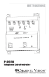
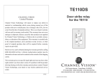
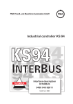
1
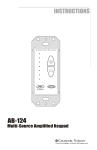
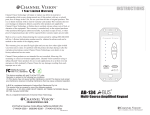
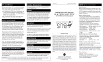
AUX
UNLOCK
DOOR 1
CHIME 1
DOOR 1
TELCO
INPUT
CHIME 2
DOOR 2
TELCO
OUTPUT
UNLOCK
DOOR 2
CO / No CO
#/*
Model
P-0921
PRO
CHANNEL
V ISION
TM
TELCO
2-DOOR TELEPHONE
ENTRY CONTROLLER
INPUT
OUTPUT
DOOR 1
PAGE
DOOR 2
POWER
P-0921
2-DOOR TELEPHONE ENTRY CONTROLLER
PRO
7
The P-0921 provides communication between two different Channel Vision
door intercoms and any phone in the house. When a visitor presses the
doorbell button the phones in the house will respond with a distinctive ring.
The home owner can then speak to the visitor by answering any of the
ringing phones in the house.
Features:
! Supports 2 Channel Vision door intercom stations
! Rings the phones when the doorbell button is pressed
! Integrated door chime contacts for triggering a traditional doorbell
! Programmable auxiliary dry contact closure
! Page output for whole-house paging system
! Can work with or without an active telephone line
! LED status indicators
! Quick and easy installation
PRO
CHANNEL
V I S IO N
CO / No CO
#/*
Model
P-0921
TM
TELCO
AUX
UNLOCK
DOOR 2
CHIME 2
UNLOCK
DOOR 1
CHIME 1
DOOR 1
DOOR 2
TELCO
OUTPUT
TELCO
INPUT
Telephone service input/output. Use either the RJ-45 or screw terminals.
CHIME 1 and 2 are dry contacts which close whenever the
corresponding doorbell button is pressed.
Unlock Door 1 and 2 allows a door strike relay to be triggered
when these terminals are shorted by the press of a button.
AUX contact closure can be configured to
close when STRIKE 1 is active OR when
PAGE is active
2-DOOR TELE
PHONE
ENTRY CONT
ROLLER
Enables operation
when no active CO
line is present
Selects the activation
key (either # or *)
INPUT
OUTPUT
DOOR 1
PAGE
DOOR 2
Audio page output
for whole-house
paging systems
POWER
Door 1 and 2 are connections for Channel Vision
Door stations.Use either RJ-45 or screw terminal
connections.
2
Other Telephone Entry Components
Door-Intercom Units:
Your telephone entry system will require at least one of the following
compatible door-intercom stations. These door intercoms are constructed
of 1/4” solid brass and are offered in 9 different finishes to match the most
popular door hardware. They can be ordered with or without a hidden
camera for covert surveillance. Both color and black & white camera
options are available.
DP Intercom... is a
large unit, measuring
6-1/2” tall by 4-3/8”
wide, that was
designed to look
good in large-scale
entry ways.
IU Intercom... is a
single gang unit,
measuring 4-1/2” tall by
2-3/4” wide, perfect for
locations where the
larger DP intercom unit
is not desirable.
Part numbering: DP and IU Intercom Options
XX-0212_
Blank
P
Channel Vision compatible (C-0920/P-0920/P-0921)
Panasonic compatible
212
222
232
242
252
262
272
282
302
White
Polished Brass
Antique Brass
Chrome
Oil Rubbed Bronze
Antique Copper
Satin Silver
Black
Satin Nickel
0
5
6
No camera
Black and white camera
Color camera
DP
IU
Large size (6-1/2” x 4-3/8”)
Single-gang size (4-1/2” x 2-3/4”)
TE110DS... is a dry contact relay that can be
connected in-line between the P-0921 and the door
intercom station. It is activated by the same
commands that control STRIKE 1 and STRIKE 2.
3
Basic Setup & Operation
When the button is pressed on the door-intercom, the phones in the house
will ring. If a doorbell chime and transformer are connected to the CHIME
contact, the doorbell chime will also be heard.
If the phone is answered within 20 seconds, it will be automatically
connected to the door-intercom. If the phone is answered after 20 seconds
simply press ## (or **) to be connected.
(Note: the activation key is determined by the switch labeled “# or *”)
While speaking to the door-intercom, the STRIKE 1 contact can be
activated by pressing #71 (or *71).
The Unlock Door terminals can be momentarily shorted with a simple push
button which will activate the strike without the use of a telephone.
To send a whole-house page from any phone, press #5 (or*5).
(see the following page for a full list of user codes).
Doorbell
Chime
and
Transformer
Telephone
Service
Simple push button (optional)
AUX
CHIME 1
DOOR 1
TELCO
INPUT
UNLOCK
DOOR 1
Strike
power
supply
UNLOCK
DOOR 2
CHIME 2
DOOR 2
TELCO
OUTPUT
CO / No CO
PRO
CHANNEL
V ISION
#/*
Model
P-0921
TM
TELCO
2-DOOR TELEPHONE
ENTRY CONTROLLER
To Strike
Mechanism
INPUT
OUTPUT
DOOR 1
PAGE
DOOR 2
POWER
To Whole-House
Paging System
4
House
Telephones
Channel Vision Compatible
Door Intercom Station
User Codes
User codes for P-0921
Replace x with # or * depending on the position of the #/* switch.
Key codes
Function
xxx1
xxx2
xx
Talk with DOOR 1
Talk with DOOR 2
When on a phone call: places call on hold & answers door -press again to go back
When not on a phone call: answers the last door station activated
Activate page out function
x5
(the following codes work while you talk to the door)
x71
Activate STRIKE 1 (can use AUX terminals or TE110DS module)
x72
Activate STRIKE 2 (Requires TE110DS module)
Examples: (assuming the P-0921 is set for # operation)
The user dials ## - they will be connected to the last door station that was
activated. Pressing ## again will toggle to the other door.
The user dials ###1 - they will be connected to DOOR 1
(Then, while talking)
The user dials #71 - strike 1 will be activated.
The user dials ###2 - they will be connected to DOOR 2
(Then, while talking)
The user dials #72 - strike 2 will be activated.
Call Waiting functions
Situation: Doorbell is pressed when you are already on the phone.
You will hear: You will hear call waiting beeps, press ## (or **) to be
connected.
Situation: You have placed the caller on hold and switched to the door
intercom.
You will hear: Occasional beeps reminding you that a call is holding.
Situation: You are speaking to the door intercom when an incoming phone
call is detected by the system.
You will hear: Beep, beep, pause... Beep, beep, pause... etc.
Situation: The doorbell is pressed at the same time as an incoming call is
detected.
When you pick up the receiver: you will be connected to the incoming call.
You will hear: Beeps corresponding to the distinctive ring for the door
intercom being activated.
5
Programming Codes
To program the advanced options of the P-0921 pick up any telephone in
the system and enter the touch-tone codes listed in the chart below.
Default Settings:
CHIME 1 and 2 are momentary closure.
STRIKE 1 and 2 is set for a 3 second closure period
AUX is configured to provide contact closure when STRIKE 1 is active
Distinctive Ring is set for option 3
CHART 1
Programming procedures for P-0921
x0yz
FIRST: Call the door station from a telephone (press ## or **).
Replace x, y and z with numbers shown below. When finished, press # or *
and listen for confirmation beep. (See example below).
0
1-9
1-9
1-5
1-2
1
2
3
6
7
8
Momentary closure for strikes and chimes contacts (300 msec)
For CHIME 1 & CHIME 2 (See CHART 1-A)
For STRIKE 1 & STRIKE 2 (See CHART 1-B)
For distinctive ring selection (See CHART 1-C)
Press 1 for contact closure when STRIKE 1 is active,
Press 2 for contact closure when Page is active.
To program CHIME 1
To program CHIME 2
To program Distinctive Ring
To program AUX contact
To program STRIKE 1
To program STRIKE 2
0 Press 0 to enter the programming mode, press # (or*) to save changes.
Hang up the phone to exit without saving.
#
*
If the P-0921 is set for # operation (determined by #/* switch)
If the P-0921 is set for * operation (determined by #/* switch)
CHART 1-A
CHART 1-B
CHIME duration
Duration of
Option
contact closure
3 seconds
1
2
5 seconds
3
8 seconds
4
16 seconds
5
25 seconds
60 seconds
6
120 seconds
7
180 seconds
8
240 seconds
9
STRIKE duration
Duration of
Option
contact closure
3 seconds
1
2
5 seconds
3
8 seconds
4
16 seconds
5
25 seconds
60 seconds
6
120 seconds
7
180 seconds
8
240 seconds
9
CHART 1-C
Selecting a distinctive ring
# operation
operation
Door 1 Door 2 Door 1 Door 2
2/1
2/2
2/3
2/4
2/3
2/4
2/1
2/2
3
5
2/3
2/5
2/3
2/5
3
5
3
5
3
5
*
1
2
3
4
5
1st ring/2nd ring
examples:
2/1 = “ring, ring, ... ring”
2/3 = “ring, ring, ... ring, ring, ring”
Example: (assuming the P-0921 is set for # operation)
First, access the intercom system by pressing ##.
To set STRIKE 2 to operate for 8 seconds, pick up any touch-tone phone
in the system and dial: #073# (listen for confirmation tone)
6
To set STRIKE 2 to operate for 25 seconds, pick up any touch-tone phone
in the system and dial: #085# (listen for confirmation tone)
Four Door Application
AUX
CHIME 1
DOOR 1
TELCO
INPUT
Set this switch for
# operation
DOOR 2
CHIME 2
UNLOCK
DOOR 2
CO / No CO
TELCO
OUTPUT
Telephone
Service
UNLOCK
DOOR 1
Two of the P-0921 can be used to serve up to 4 different door-intercoms.
Simply connect and configure the units as shown below. Note: be sure to
set one unit for # operation and the other unit for *.
#/*
PRO
CHANNEL
V ISION
Model
P-0921
TM
TELCO
2-DOOR TELEPHONE
ENTRY CONTROLLER
INPUT
DOOR 1
PAGE
Door 1
DOOR 2
Door 2
Set this switch for
* operation
AUX
CHIME 1
DOOR 1
TELCO
INPUT
POWER
UNLOCK
DOOR 1
OUTPUT
UNLOCK
DOOR 2
CHIME 2
DOOR 2
TELCO
OUTPUT
CO / No CO
PRO
CHANNEL
V ISION
#/*
Model
P-0921
TM
TELCO
2-DOOR TELEPHONE
ENTRY CONTROLLER
INPUT
OUTPUT
House
Telephones
DOOR 1
Door 3
PAGE
DOOR 2
Door 4
POWER
7
Using the TE110DS
The TE110DS is not always required when using the P-0921, because the
P-0921 has a built in AUX relay that can be programmed to control one
electronic door strike. However, it may still be used for applications that
require a remote contact closure that is located near the door intercom
station.
If using the RJ-45 connection on the P-0921, simply connect the green and
green-white wires from the CAT5 to the terminal inputs and outputs of the
TE110DS as shown below. If using the screw terminal connectors on the
P-0921, simply use the same
Connection Details
Green/Green-White wires
From P-0921
(Door 1 or Door 2)
Cut the outer jacket of the
CAT5 wire. Separate and
cut the green & green-white.
Connect them as shown.
Leave all other wires intact.
TE110DS
Door Intercom Station
8
Strike
power
supply
To Strike
Mechanism
Using the Page Out Function
One major benefit of the 2-Door Telephone Entry System is that many
different components can be integrated with it. The system below
integrates the Page Out feature of the P-0921 with the local audio input
on the P-1014 1x4 CAT5 Audio Distribution Module. When a page is sent
from the P-0921 it will interrupt the main audio source feeding the P-1014
so the page will be heard through the audio system’s speakers. This is a
great way to make pages audible in multiple areas throughout the home.
C HANNEL V ISION
C HANNEL V ISION
C HANNEL V ISION
Hallway
Pwr
Source
Bathroom
Pwr
Source
C HANNEL V ISION
Dining Room
Pwr
Source
Kitchen
Pwr
Source
AB-124
Amplified Keypad
Model
P-1014
System
Input
Telephone
Service
System
Signal
Priority
Zone 2
ion
Expans
Output
Zone 4
Zone 3
tribution
DIO Dis
1 x4 AU
IR
Module
Power
Status
+12VDC
+24VDC
Emitters
Local
Local
Input
R
P-1014
AUX
DOOR 1
CHIME 1
UNLOCK
DOOR 1
L
TELCO
INPUT
Zone 1
UNLOCK
DOOR 2
CHIME 2
DOOR 2
TELCO
OUTPUT
CO / No CO
PRO
CHANNEL
V ISION
#/*
Model
P-0921
TM
TELCO
RCA “Y”
cable
2-DOOR TELEPHONE
ENTRY CONTROLLER
INPUT
OUTPUT
DOOR 1
PAGE
DOOR 2
POWER
Sat radio
P-0921
DVD player
AB-202
Input
Module
CD player
AUDIO
L
Receiver
By
AB-202
OUTPUT
House
Telephones
R
STATUS
12VDC
C HANNEL V ISION
TM
STATUS
IR
IR EMITTERS
Door
9
Stripping and Connecting CAT5 Wire
CAT5 cable should be stripped with a proper stripping tool, such as Channel
Vision’s J-110 tool.
1. Place the CAT5 between the blade and the first notch of the J-110 tool.
Blade
Cat5
2. Rotate the tool only once. Multiple
turns will cause you to cut into the
inner wires.
Rotate
1 turn only
3. Inspect the inner wires for damage.
If any wires are cut start over at step 1.
Slight
pressure
Check for damage
TIA-568A RJ-45 Modular Plug
Side view:
Top view:
10
Green/White
Green
Orange/White
Blue
Blue/White
Orange
Brown/White
Brown
Troubleshooting
1) When the doorbell is pressed the phones do not ring, but you
can activate and speak to the door station by pressing *1 (or #1
depending on setup).
a. Make sure that you have the correct power supply and that it is
supplying 12 VAC.
b. Measure the AC voltage on the “TELCO Output” terminals at the
time when the unit should be ringing (just after the doorbell button
is pressed). There should be between 70 - 90 VAC across the
terminals during a ring cycle.
2) The phones in the house cannot communicate with the door
station.
a. Make sure the power supply is plugged in.
b. Make sure the phones are connected to the “TELCO Output” on the
telephone entry controller. To be sure of this, connect one phone
directly to the “TELCO Output” screw terminals and test the unit.
3) A static or “screeching” noise is heard when speaking to the
door station.
a. If DSL is present in the system, install a DSL filter (model P-0411)
on the phone line before the telephone entry controller.
4) The TE110DS does not activate.
a. Make sure you’re pressing the correct key sequence.
If already speaking to the door station, just press *71 (or #71).
If not already speaking to the door station, press *1*71 (or #1#71).
b. Measure the voltage on the screw terminals labeled “INTERCOM”
When the system is idle, there should be 1 VDC on the terminals.
When speaking to the door station, there should be about 6 VDC
on the terminals.
When the TE110DS is activated there should be at least 10 VDC on
the terminals.
Specifications:
Connectors:
Screw terminals and RJ-45 (TIA 568A)
REN:
0.1
Ring Output:
>5 (capable of ringing >10 phones with a REN of 0.5)
Power Supply:
12VAC 500mA
Dimensions:
6.5” x 7.0” x 1.5”
Specifications subject to change without notice.
11
Channel Vision Technology will repair or replace any defect in
material or workmanship which occurs during normal use of this
product with new or rebuilt parts, free of charge in the USA, for two
years from the date of original purchase. This is a no hassle warranty
with no mail in warranty card needed. This warranty does not cover
damages in shipment, failures caused by other products not supplied
by Channel Vision Technology, or failures due to accident, misuse,
abuse, or alteration of the equipment. This warranty is extended only
to the original purchaser, and a purchase receipt, invoice, or other
proof of original purchase date will be required before warranty
repairs are provided.
Mail in service can be obtained during the warranty period by calling
(800) 840-0288 toll free. A Return Authorization number must be
obtained in advance and can be marked on the outside of the shipping
carton.
This warranty gives you specific legal rights and you may have other
rights (which vary from state to state). If a problem with this product
develops during or after the warranty period, please contact Channel
Vision Technology, your dealer or any factory-authorized service
center.
www.channelvision.com
234 Fischer Avenue, Costa Mesa, California 92626 USA
(714)424-6500 (800)840-0288 (714)424-6510 fax
email: [email protected]
500-113 rev D3