1
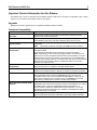
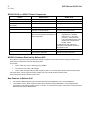
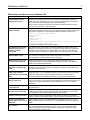
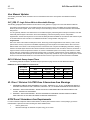
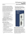
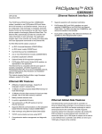
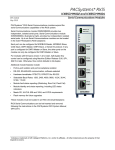
PACSystems* RX3i IC695NIU001 PLUS Ethernet Network Interface Unit GFK-2598 March 2011 The PACSystems* RX3i Ethernet NIU PLUS, IC695NIU001, makes it possible to use PACSystems RX3i and Series 90-30 I/O remotely on an Ethernet network. Once set up by configuration, data exchange is completely automatic. System control can be provided by any master device capable of exchanging Ethernet Global Data (EGD). The Ethernet NIU automatically provides the controller with status information in each exchange. The application program logic in the controller can monitor this status data, and issue appropriate commands to the Ethernet NIU. ▪ ▪ ▪ ▪ Supports operation with redundant controllers PACSystems RX7i and RX3i controllers can send selected COMMREQs to the RX3i ENIU via EGD. The ENIU executes the COMMREQs and returns the results to the controller. During EGD configuration, RX3i Ethernet interfaces are identified by their Backplane/Slot locations. Supports display of module hardware revision, serial number and date code in Machine Edition Logic Developer software. An RX3i Ethernet NIU station consists of: ▪ ▪ ▪ ▪ ▪ ▪ ▪ NIU OK I/O FORCE an RX3i power supply (IC695PSxxxx) NIU SCANNING I/O OUTPUTS ENABLED STATUS SYS FAULT the RX3i Ethernet NIU (IC695NIU001) COM1 COM2 an RX3i Universal Backplane (IC695CHS0xx) one or more RX3i Ethernet modules (IC695ETM001) RESET NIU001+ proprietary application software optional Series 90-30 expansion backplanes. PACSystems RX3i and/or Series 90-30 modules, as appropriate for the application. The Ethernet NIU is compatible with the same types of modules, backplanes, and other equipment as a PACSystems RX3i CPU. For a list of compatible products, see the PACSystems RX3i Hardware and Installation Manual, GFK-2314. This module requires Machine Edition Logic Developer software, version 5.51 or later. COM 1 Ethernet NIU001 PLUS Features ▪ 20Kbytes of optional local logic. Supports all languages except C programming. ▪ ▪ ▪ ▪ ▪ ▪ ▪ ▪ * 10 Mbytes of built-in flash memory for local user data storage. Battery-backed Real Time Clock. In-system upgradeable firmware. Two serial ports: an RS-485 serial port and an RS-232 serial port. Supports Ethernet communications via the backplanebased Ethernet Interface module (IC695ETM001) Data exchange using EGD TCP/IP communication services using SRTP Comprehensive station management/diagnostic tools indicates a trademark of GE Intelligent Platforms, Inc. and/or its affiliates. All other trademarks are the property of their respective owners. COM 2 2 RX3i Ethernet NIU001 Plus GFK-2598 Ethernet Global Data Features Ethernet NIU COMMREQ Support The Ethernet NIU communicates with its controller via EGD exchanges. One exchange is used to send outputs to the ENIU and another exchange is used to send inputs back to the controller. The ENIU supports receiving outputs from redundant controllers. By sending the EGD exchange to a group address both controllers can receive the inputs. Up to 1300 bytes of outputs can be sent to a set of ENIUs from a controller. Each ENIU can send up to 1300 bytes of inputs to the controller. The Ethernet NIU supports COMMREQs that are sent to it by a C block application in a PACSystems RX7i or RX3i controller. This feature is not available with other types of controllers. Ladder code in the RX7i or RX3i CPU interfaces to the C block. The C block sends COMMREQ commands to the Ethernet NIU in an Ethernet Global Data Exchange. The Ethernet NIU executes the COMMREQ and sends the results back to the RX7i or RX3i using another EGD exchange. The following COMMREQs can be sent in this way: A typical system might consist of a controller with five ENIUs. The controller sends 1300 bytes of outputs and each ENIU sends 100 bytes of inputs to the controller. This typical system would have its I/O updates occur in less than 25 milliseconds. If the controller scan time is greater than 25 milliseconds, the update occurs at the controller’s scan rate. This performance timing is a guideline, not a guarantee, and assumes that there is no other traffic on the Ethernet link to the I/O. Performance data for other system configurations can be found in the Ethernet NIU User’s Manual, GFK-2439. ▪ ▪ ▪ ▪ ▪ ▪ ▪ Modbus Master – function codes 1, 2, 3, 4, 5, 6, 7, 15, 16, 17 Genius – enable/disable outputs, switch BSM, clear fault, clear all faults, assign monitor, read diagnostic PROFIBUS Master – COMMREQs 1, 2, 4, 5, 6 Motion (DSM314/DSM324) – load parameters High Speed Counter – Data command DeviceNet Master – COMMREQs 1, 4, 5, 6, 7, 9 Analog Module – HART Protocol COMMREQs. In addition, any COMMREQ supported by a module in the Ethernet NIU can be sent as a Generic COMMREQ, with the exception of DeviceNet Master Send Extended Explicit Message. For more information, see the PACSystems RX3i Ethernet NIU User’s Manual, GFK-2439. Specifications for IC695NIU001 PLUS Real Time Clock battery life Estimated 5 years. Battery must be replaced every 5 years on a regular maintenance schedule. Note: The module is shipped with a pull-tab on the battery. The pull-tab should be removed before installing the module. Power requirements +3.3 VDC: 0.52 Amps nominal +5.0 VDC: 0.95 Amps nominal Operating Temperature 0°C to 60°C (32°F to 140°F) Floating point Yes Boolean execution speed, typical 0.072 ms per 1000 Boolean instructions Embedded communications RS-232, RS-485 Serial Protocols supported Modbus RTU Slave, SNP, Serial I/O, Modbus RTU Master by application “C” block Backplane Dual backplane bus support: RX3i PCI and 90-30-style serial PCI compatibility System designed to be electrically compliant with PCI 2.2 standard Ports RS-232 Serial Port RS-485 Serial Port External isolation recommended. (For details, see RS-485 Port Isolator, IC690ACC903, GFK-1663.) For environmental specifications and compliance to standards (for example, FCC or European Union Directives), refer to the PACSystems RX3i Hardware and Installation Manual, GFK-2314. RX3i Ethernet NIU001 Plus 3 GFK-2598 Ordering Information Description RX3i Ethernet Network Interface Unit RX3i Ethernet Module Package consisting of RX3i Ethernet NIU IC695NIU001 and one Ethernet Transmitter Module IC695ETM001 Package consisting of RX3i Ethernet NIU IC695NIU001 and two Ethernet Transmitter Modules IC695ETM001 Real Time Clock Battery RX3i Power Supply, 40 Watt High Capacity Universal AC Power Supply RX3i Power Supply, 40 Watt High Capacity 24 VDC Power Supply RX3i Multi-Purpose Power Supply, 40 Watt High Capacity Universal AC RX3i Multi-Purpose Power Supply, 40 Watt High Capacity 24 VDC [Optional] RS-232 Cable Rx3i Standard 12 Slot Universal Backplane Rx3i Standard 16 Slot Universal Backplane Mini Converter Kit with Cable, RS-485/RS-232 RS-485 Port Isolator Note: For Conformal Coat option, please consult the factory for price and availability. NIU Plus Battery and Switch Locations Front View Rear View NIU OK I/O FORCE NIU SCANNING I/O OUTPUTS ENABLED STATUS SYS FAULT COM1 COM2 RESET NIU001+ CPU MODE STOP RUN IO ENABLE COM 1 COM 2 RUN OUTPUT DISABLE Catalog Number IC695NIU001 IC695ETM001 IC695NTK001 IC695NTK002 IC690ACC001 IC695PSA040 IC695PSD040 IC695PSA140 IC695PSD140 IC200CBL001 IC695CHS012 IC695CHS016 IC690ACC901 IC690ACC903 4 RX3i Ethernet NIU001 Plus GFK-2598 Switches The Ethernet NIU Plus has two switches. The Reset switch is not used. The three-position Run/Stop switch is located behind the protective door, as shown above. Unlike the Run/Stop switch on a CPU module, on an Ethernet NIU the use of this switch is disabled by default. If the switch is to be used to control the Run or Stop mode operation of the NIU, clear faults, and/or prevent writing to program memory or configuration, it must be enabled on the Settings Tab of the Ethernet NIU configuration in the folder, and stored to the ENIU. Run Stop, I/O Enabled Stop, I/O Disabled Real Time Clock Battery The NIU Plus is shipped with a real time clock (RTC) battery (IC690ACC001) installed, with a pull-tab on the battery. The pull-tab should be removed before installing the module. The RTC battery has an estimated life 5 years. Battery must be replaced every 5 years on a regular maintenance schedule. Release History Catalog Number FW Revision Comments IC695NIU001-AAAA 6.80 Initial release of NIU001 PLUS. IC695NIU001-DP 6.01 Provides OEM protection in flash-based systems that do not use a battery. See GFK-2419P for details and problems resolved. IC695NIU001-DN 6.00 Adds User Defined Types, Variable Indexed Arrays, Logic Driven Write to Flash, and Backplane Operations Controller Enhancement features. See GFK-2419N for details and problems resolved. IC695NIU001-DM 5.70 Enables support that is functionally identical to the IC695CMX128 for the IC695RMX128. IC695NIU001-CL 5.61 Corrects the problem described in GFK-2419L. IC695NIU001-CL 5.60 Supports the IC695PMM335 PACMotion Multi-Axis Motion Controller and other new features, and corrects the problems listed in GFK-2419L. IC695NIU001-CK 5.50 Supports Run-mode store of EGD. Adds support for LREAL data type. IC695NIU001-CJ 5.03 Corrects problem of Corrupted User Memory issue after a power cycle. Corrects problem in 5.02 firmware only, in which loss of certain IC694 and IC693 modules in an expansion rack caused the outputs of similar modules in expansion racks to be disabled when the “Loss of Module” fault was configured as diagnostic. IC695NIU001-BH 5.02 Fixed an issue where certain IC694 and IC693 modules in the main rack did not transition to stop mode after a “Loss of Module” fault was logged. IC695NIU001-BG 5.00 Supports Proficy Process Systems rel. 1.00, Scan_Set_IO, Quality Function Blocks, Optional UDF Parameters, IEC Transitionals, SNPT Network time sync. IC695NIU001-BF 3.83 Support for PACSystems RX3i Serial Communications modules IC695CMM002 and CMM004. IC695NIU001-BE 3.82 Refer to GFK-2419D for new features and issues resolved. IC695NIU001-BD 3.81 Support for eight ETM modules in the main backplane. IC695NIU001-AC 3.52 Refer to GFK-2419B for issues resolved. IC695NIU001-AB 3.51 Refer to GFK-2419A for issues resolved. IC695NIU001-AA 3.50 Initial release of NIU001. RX3i Ethernet NIU001 Plus 5 GFK-2598 Important Product Information for this Release The NIU001 Plus is a drop-in replacement for the NIU001 Classic module, with no changes to configuration, logic or wiring required. For new features and problems resolved, see page 6. Upgrades NIU001 Plus firmware upgrades are not compatible with NIU001 Classic hardware. Functional Compatibility Product Compatible Versions Proficy* Machine Edition Logic Developer Proficy Machine Edition Logic Developer 6.50 or later is required to use the NIU001 PLUS release 6.80 features. NIU001 Classic and NIU001 PLUS The NIU001 Classic and NIU001 Plus are interchangeable. An application created for an NIU001 PLUS can be used with an NIU001 Classic and vice versa. Backplanes, power supplies, and system modules As listed in the PACSystems RX3i System Manual, GFK-2314C or later, except as noted below. Note: The NIU001 modules do not support the PMM335 motion controller. Series 90-30 Expansion Rack Compatibility Series 90-30 expansion racks, both local and remote, are supported by the PACSystems RX3i. The PACSystems RX3i ENIU does not operate in a Series 90-30 Rack. Note: The RUN LED on the 90-30 Power Supply located in an expansion rack (both local and remote) will not be illuminated when the RX3i System is in RUN mode and there are only input modules in the expansion rack. The RUN LED on the 90-30 Power Supply located in an expansion rack (both local and remote) will be illuminated when the RX3i System is in RUN mode and there are output modules in the expansion rack. Series 90-30 Main Rack Compatibility Series 90-30 Main Racks cannot be used in a PACSystems RX3i system. Series 90-30 CPUs do not operate in PACSystemsRX3i Racks. Isolated 24V power In applications that use the IC69xALG220/221/222, consult PACSystems RX3i Hardware and Installation Manual, GFK-2314 for details of wiring the 24V power. COMMREQ to PBM300 In Release 3.0, the behavior of the COMMREQ fault output on a COMMREQ sent to the PROFIBUS master module IC695PBM300 has been changed to be compatible with the Series 90-30 CPU366 PROFIBUS Master. Previously, the fault output is enabled when the module receives a COMMREQ and it is busy. Now, the busy condition does not result in the fault output enabled. Recommended IC200ALG240 revision When a VersaMax* system Genius* Network Interface Unit (IC200GBI001) interoperates with a Genius Bus Controller located in a PACSystems PLC, and the VersaMax system contains an IC200ALG240 Analog Input Module, it is recommended to update the IC200ALG240 firmware to Revision 1.10 or later. Use firmware update kit 44A752313-G01, available in Knowledge Base Article i023269 atwww.ge-ip.com/support. Configuration of IC694MDL754 Always configure 16 bits of module status when using this module. Configuring 0 bits of module status will result in invalid data in the module’s ESCP status bits. 6 RX3i Ethernet NIU001 Plus GFK-2598 NIU001 PLUS vs. NIU001 Classic Comparison Feature NIU001 Classic NIU001 PLUS Processor Celeron 300 MHz Atom 510, 1.1 GHz Real Time Clock Battery Not supported IC690ACC001 Memory Backup and Real Time Clock Battery IC698ACC701 Not supported Embedded communications RS-232, RS-485 RS-232, RS-485 Power requirements +3.3 VDC: 1.25 Amps nominal +5.0 VDC: 1.0 Amps nominal +3.3 VDC: 0.52 Amps nominal +5.0 VDC: 0.95 Amps nominal Performance Same as CPU310. For performance data, Note: refer to the PACSystems CPU Reference Manual, GFK-2222. Boolean execution speed, typical 0.181 ms per 1000 Boolean instructions 0.072 ms per 1000 Boolean instructions Battery and switch locations For details, refer to the Ethernet NIU User’s Manual, GFK-2439. For details, see page 3 or the Ethernet NIU User’s Manual, GFK-2439 The processor has been upgraded from a 300MHz Celeron to a 1.1 GHz Atom processor. There have been many associated changes to the performance compared to the NIU001 Classic. For performance data, refer to the PACSystems CPU Reference Manual, GFK-2222R or later. NIU001+ Problems Resolved by Release 6.80 SVC_REQ 57: Logic Driven Write to Nonvolatile Storage: In previous versions of the firmware, writing a partial block of word memory would result in incorrect data being written. For example: %R1 to %R10 are written to flash using SVC_REQ 57 The values of %R3, %R4, %R6 changes %R1 to %R10 are again written to flash using SVC_REQ 57. The actual values written to flash will be incorrect. If all of the values, %R1 through %R10 have changed, the correct values would be written to flash. This issue has been fixed in firmware version 6.80 New Features in Release 6.80 This release enables support that is functionally identical to the IC695NIU001 on the new IC695NIU001+. The hardware revision, serial number and date code of the Ethernet NIU IC695NIU001+ can be displayed after upgrading to Proficy Machine Edition version 6.5 or later. To access this information, select Online Commands, Show Status and then click the Details button. RX3i Ethernet NIU001 Plus 7 GFK-2598 Restrictions and Open Issues in Release 6.80 Subject The Ethernet module fails to exchange EGD properly during power cycling Description Very rarely, after experiencing multiple rapid power cycles, the CPU may fail to establish communication with one or more modules in the backplane at power up. When this occurs, several pairs of "Loss of, or missing option module" and "Reset of option module" faults will be logged in the controller fault table. If the module is an ETM, an event 30H is recorded in its station manager event log. To recover from this issue, cycle power again. Loss of power supplies after firmware update A Loss of Power Supplies after firmware update may occur. This does not happen with all firmware updates and will not occur if the system is power cycled after the firmware upgrade has completed. The following fault is displayed when this issue occurs: Loss of, or missing option module Error Code 36 Group 4 Action 3:Fatal Task Num 9 Fault Extra Data: 01 58 02 4f 80 08 0a 07 00 00 00 00 00 00 00 00 00 00 00 00 00 00 00 00 To correct this condition, power cycle the system. Hot Swapping some analog modules slowly result in modules not being recognized Occasionally during a hot insertion (hot swap) of IC695 Non-Isolated Analog Input Modules, input channels may take up to 2 seconds to reflect actual input values after the module ok bit is enabled in the module status word. This only occurs when hot insertion has been done slowly (i.e. approximately 1.5 seconds to insert the module). Ethernet disconnect during Word for Word change If the Ethernet connection is broken during a word–for-word change, the programmer may not allow a subsequent word-for-word change after reconnecting. Recommendation: go offline and then back online again. Simultaneous clears, loads and stores not supported Multiple programmers may not change ENIU contents at the same time. The programming software may generate an error during the operation. Simultaneous loads from a single ENIU are allowed. Hardware configuration Not Equal after changing target name If a hardware configuration is stored to flash and the name of the target is subsequently changed in the programming software, the hardware configuration will go Not Equal and will not Verify as equal. Controller and IO Fault Tables may need to be cleared twice to clear faulted state Both Controller and IO fault tables may need to be cleared to take the ENIU out of Stop/Fault mode. If one of the tables contains a recurring fault, the order in which the tables are cleared may be significant. Recommendation: if the ENIU is still in Stop/Fault mode after both tables are cleared, try clearing the fault tables again. Setting force on/off by storing initial value After a force on or force off has been stored to the ENIU, it cannot be switched from force on to force off or vice-versa by downloading initial values. Recommendation: turn off the force by doing a download, and then change the force on or off by another download. Number of active programs returned as zero The SNP request Return Controller Type and ID currently returns the number of active programs as zero. Serial I/O failure at 115K during heavy interrupt load Rarely, data corruption errors occur during serial communications when running at 115K if there is a heavy interrupt load on the ENIU. Recommendation: under heavy load applications, restrict serial communications to 57K or lower. SNP ID not always provided Unlike the Series 90-30, the RX3i ENIU’s SNP ID does not appear in the Machine Edition programmer Show Status display. Service Request 11 will always return zeros. Second programmer can change logic while in Test & Edit mode While currently active in a Test and Edit session using Machine Edition on one PC, Machine Edition running on another PC is not prevented from storing new logic to the ENIU. Must have logic if poweringup from flash If no user logic exists in the CPU RAM when a write to flash is performed, the CPU may not properly load from flash after a power cycle. In order to guarantee proper power up from flash, insure that both hardware configuration and logic have been stored to RAM before writing to flash. 8 RX3i Ethernet NIU001 Plus GFK-2598 Subject Description Two loss of module faults for Universal Analog Module Occasionally, the hot removal of the Universal Analog Input Module (IC695ALG600) results in two “Loss of I/O Module” faults instead of one. Power up of Series 90-30 HSC module may take up to 20 seconds As power is applied to a 90-30 High-Speed Counter, the "module ready" bit in the status bits returned each sweep from the module may not be set for as long as 20 seconds after the first ENIU sweep, even though there is no "loss of module" indication. I/O data exchanged with the module is not meaningful until the module has set this bit. Informational fault at power up Intermittently during power-up, an Informational non-critical ENIU software fault may be generated with fault extra data of 01 91 01 D6. This fault has no effect on the normal operation of the ENIU. But if the hardware watchdog timer expires after this fault and before power has been cycled again, the outputs of I/O modules may hold their last state, rather than defaulting to zero. Extended Memory Types for I/O Triggers %R, %W and %M cannot be used as I/O triggers. Possible Machine Edition inability to connect Infrequently, an attempt to connect a programmer to an ENIU via Ethernet is unsuccessful. The normal connection retry dialog is not displayed. Recommendation: Reboot the computer that is running the programmer. SNP Update Datagram message If an Update Datagram message requests 6 or fewer bits or bytes of data, the ENIU returns a Completion Ack without Text Buffer. The protocol specifies that the returned data should be in the Completion Ack message, but it may not be. GBC30 may not resume operation after power cycle In rare instances, a GBC30 in an expansion backplane may not resume normal operation after a power cycle of either the expansion backplane or the main backplane. To restore GBC operation, power cycle the rack again. Configuration of third-party modules Do not specify a length of 0 in the configuration of a third-party module. The module will not work properly in the system. Power supply status after ENIU firmware update The ENIU reports a “Loss of or missing option module” fault for the IC695PSD140 RX3i power supply following an update of ENIU firmware. The slot appears empty in the programmer’s online status detail view. The power supply continues to operate normally. Recommendation: Power cycle to restore normal status reporting. Power supply status after power cycling Rarely, turning a power supply on or off may not result in an Add or Loss fault. Also, the slot will appear empty in the programmer’s online status detail view. The power supply continues to operate normally. Power cycle to restore normal status reporting. Don’t use multiple targets If the hardware configuration is stored from one target and logic is stored from a different target, powering-up from flash will not work. The observed behavior is that, following a power up from flash, Machine Edition reports hardware configuration and logic "not equal". Missing Loss of Terminal block fault The IC695ALG600/608/616 analog input modules do not produce a “Loss of terminal block” fault if the hardware configuration is stored or the module is hot-inserted when the terminal block is not locked into place. Sequence Store Failure When downloading projects with very large hardware configurations or which use large amounts of user memory, it is possible to encounter a controller Sequence Store Failure error when writing the configuration to flash. To work around this error, either or both of the following actions may be helpful: 1. Perform an explicit clear of flash prior to performing the write. 2. Increase the operation timeout used by Machine Edition prior to performing the write. This is done by expanding the Additional Configuration in the Inspector window for the target controller, and adjusting the Request Timeout. The timeout may need to be increased to as much as 60,000 msec, depending on the amount of memory used and the condition of the flash memory. IC694MDL754: Must configure module status bits Always configure 16 bits of module status when using this module. Configuring 0 bits of module status will result in invalid data in the module’s ESCP status bits. RX3i Ethernet NIU001 Plus 9 GFK-2598 Subject Description IC695ALG600 Lead Resistance Compensation setting A configuration store operation fails if a channel is configured for 3-wire RTD with Lead Resistance Compensation set to Disabled. A Loss of Module fault is logged in the I/O Fault table at the end of the store operation. Recommendation: to recover the lost module, change the configuration to enable Lead Resistance Compensation and power-cycle the module. WinLoader may stop operating On computers running Windows 2000 and using some versions of Symantec Antivirus protection, WinLoader will "lock up" if used in advanced mode. Recovery requires cycling the computer's power. WinLoader does not detect PC COM port in use when upgrading PACSystems ENIU. WinLoader does not detect if a PC's COM port is in use when attempting to connect to a PACSystems ENIU to perform a firmware upgrade. If the port is already in use it displays the status "trying to connect" followed by "waiting for target." To proceed with the upgrade, press the "abort" button and disconnect the other application that is using the COM port. WinLoader does not display error when it can't connect serially with PACS ENIU. WinLoader does not display an error message if it cannot connect to the ENIU when attempting to connect to a PACSystems ENIU to perform a firmware upgrade. This occurs if the cable is physically not connected to the ENIU or if the ENIU's serial port is not configured for the same baud as WinLoader. In this case Winloader displays the status "trying to connect" followed by "waiting for target." To proceed with the upgrade, press the "abort" button and correct the cable or baud rate setting. Operational Notes Subject Description Interrupt block only executed once if several interrupts are triggered in short interval When multiple interrupts are triggered during the interrupt latency period, it is possible that interrupt blocks will only be executed one time even though the interrupt trigger has occurred more than once. The likelihood of this occurring will increase if the system interrupt latency has increased due to the specific configuration and use of the system. This will not cause the CPU to miss a given interrupt; just consolidate the number of times an interrupt block is executed, even though the interrupt stimulus had occurred more than one time. IC695NIU001+ performance differences from IC695NIU001 The IC695NIU001+ has a different processor than was used on the IC695NIU001 and performs differently for different types of operations. Some function blocks will run faster and some will run slower on the NIU001+. Overall it is expected that most applications will run faster with the new NIU001+, but some specific projects may be slightly slower when using the new hardware. Access to Series 90-30 backplane modules is approximately 25% slower compared to the IC695NIU001. For example the IC694DSM324 sweep impact is about 350 microseconds greater in the main rack and about 250 microseconds greater in an expansion rack when using the IC695NIU001+ compared to the IC695NIU001. EGD performance is different on the new IC695NIU001+ when compared to the IC695NIU001. In general consumed data exchanges with more than 31 bytes contribute less sweep time impact and data exchanges with a size less than that contribute slightly greater sweep impact. All produced exchanges on the IC695NIU001+ have a slightly greater sweep impact compared to the IC695NIU001. EGD run mode store not supported with ETM firmware release 5.0 Performing a run mode store of EGD to an ETM001 module with release 5.0 firmware results in the Controller Fault Table filling up with “LAN System Software Fault” fault messages. This is due to the 5.0 release of ETM001 module being incompatible with run mode store of EGD. To resolve this issue, upgrade the ETM module firmware to the latest release available. 10 RX3i Ethernet NIU001 Plus GFK-2598 Subject Description Error response 1 is no longer returned for Modbus RTU requests with invalid or undefined function code Prior to Release 6.70 for the RX3i, the Modbus RTU slave protocol would return an Invalid Function Code error response (1) upon receipt of a request with an invalid or undefined function code. Starting with Release 6.70, the Modbus RTU slave ignores requests with an invalid or undefined function code, and no response is sent. Length of Serial I/O buffer (Release 5.0 or later) The "Set Up Input Buffer Function" will always allocate a buffer containing 2049 bytes. This is one byte more than previous PACSystems releases. LD-RX3i operations To perform a download to the ENIU, you must first connect to the ENIU. The connect and download functions are now separate in Machine Edition LD. Changing IP address of Ethernet interface while connected Storing a hardware configuration with a new IP address to the RX3i while connected via Ethernet will succeed, then immediately disconnect because the RX3i is now using a different IP address than the Programmer. You must enter a new IP address in the Target Properties in the Machine Edition Inspector window before reconnecting. Duplicate station address for Modbus will conflict with other nodes The default serial protocol for the RX3i is Modbus RTU. The default Station Address is 1. If the ENIU is added to a multi-drop network, care must be taken that the ENIU is configured with a unique Station Address. Nodes with duplicate Station Addresses on the same network will not work correctly. Timer operation Care should be taken when timers (ONDTR, TMR, and OFDTR) are used in program blocks that are NOT called every sweep. The timers accumulate time across calls to the sub-block unless they are reset. They function like timers operating in a program with a much slower sweep than the timers in the main program block. For program blocks that are inactive for large periods of time, the timers should be programmed to account for this catch up feature. Related to this are timers that are skipped because of the use of the JUMP instruction. Timers that are skipped will NOT catch up and will therefore not accumulate time in the same manner as if they were executed every sweep. Constant sweep Large number of COMMREQs sent to module in one sweep causes faults Constant Sweep time, when used, should be set at least 10 milliseconds greater than the normal sweep time to avoid any over-sweep conditions when monitoring or performing on-line changes with the programmer. Window completion faults will occur if the constant sweep setting is not high enough. A large number of COMM_REQs (typically more than 8) sent to one module in the same sweep may cause Module Software faults to be logged in the Controller fault table. The fault group is MOD_OTHR_SOFTWR (16t, 10h) and the error code is COMMREQ_MB_FULL_START (2). The “FT” output of the function block is also set. Recommendation: Spread multiple COMMREQs to the same module across multiple sweeps so that fewer (typically 8 or less) are sent to the module in each sweep. Also, check the FT output parameter for errors. If the FT output is set (an error has been detected), the COMMREQ could be re-issued by the application logic. Upgrading Firmware Upgrading ENIU firmware with the WinLoader utility may fail when multiple IO modules are in the main rack, due to the time required to power-cycle the rack system. If the upgrade fails, move the ENIU to a rack without IO modules and restart the upgrade process. Winloader initial connect baud rate is fixed at 19200 baud. Note that the firmware download will occur at 115.2K baud by default. If you have hyperterm open on a port, and then try to use Winloader on the same port, Winloader will often say “Waiting for Target” until the hyperterm session is closed. Hot Swap Hot Swap of power supplies or ENIUs is not supported. Serial Port Configuration COMMREQs With the following combination of circumstances, it is possible to render serial communications with the ENIU impossible: User configuration disables the Run/Stop switch User configures the power up mode to Run or Last Logic is stored in FLASH and user configures ENIU to load from FLASH on power up User application issues COMMREQs that set the protocol on both of the serial ports to something that does not permit communications to the Machine Edition programmer. RX3i Ethernet NIU001 Plus 11 GFK-2598 Subject Description Incorrect COMMREQ status for The program name for PACSystems is always "LDPROG1". When another program invalid program name name is used in a COMMREQ accessing %L memory, an Invalid Block Name (05D5) error is generated. FANUC I/O Master and Slave operation The first operation of the scan set on the master does not work after entering RUN mode. They work properly for subsequent scans. After downloading a new hardware configuration and logic, a power cycle may be required to resume FANUC I/O operation. Use Ethernet NIUs of similar performance in FANUC I/O networks. Repeated power up/down cycles of an expansion backplane containing FANUC I/O slaves may result in failure of the slaves’ operation, with the RDY LED off. Lost count at power up for Serial IO Processor The serial IO Processor (IC693APU305) will lose the first count after every power up or every time the module receives a configuration. COMMREQ status words declared in bit memory types must be byte-aligned Prior to release 3.50, the ENIU allowed configuration of COMMREQ Status Words in bit memory types on a non-byte-aligned boundary. The firmware adjusted references to the next-lowest byte boundary before updating status bits, overwriting the bits between the alignment boundary and specified location. Now, COMMREQ Status Words in bit memory types must be byte-aligned. Specify the appropriate aligned address (%I1) to ensure that the utilized location is appropriate Suspend IO function block does not suspend EGD In a Series 90-70 the SUSPEND_IO function block suspends EGD in addition to IO Scan. In PACSystems controllers the SUSPEND IO suspends only the IO Scan. STOP and RUN mode transition priority The PACSystems ENIU receives requests to change between stop and run mode from many different sources. These include (but are not limited to) Proficy Machine Edition, HMIs, the user application, and the RUN/STOP switch. Since there are many potential sources for a mode change request, it is possible to receive a new mode change request while another is already in progress. When this occurs, the ENIU evaluates the priority of the new mode change request with the mode change that is in progress. If the new mode change request has an equal or higher priority than the one already in progress, the ENIU transitions to the new mode instead of the one in progress. If, however, the new mode change request has a lower priority than the one in progress, the new mode request is discarded and the ENIU completes the mode change that is in progress. The sweep mode priorities are (listed from highest to lowest priority): STOP HALT, STOP FAULT, STOP, and RUN. (Note: The IO ENABLED/DISABLED state is not part of the mode priority evaluation.) For example, an ENIU is in RUN IO ENABLED mode and a Service Request 13 function block is executed to place the ENIU into STOP IO DISABLED mode. Before the transition to STOP IO DISABLED is completed, the RUN/STOP switch is changed from RUN IO ENABLED to RUN IO DISABLED. In this case, the ENIU ignores the new request from the RUN/STOP switch to go to RUN IO DISABLED mode because it is already processing a request to go to STOP IO DISABLED mode and STOP mode has a higher priority than RUN mode. 12 RX3i Ethernet NIU001 Plus GFK-2598 User Manual Updates The following information will be included in the next scheduled revision of the PACSystems CPU Reference Manual, GFK-2222. SVC_REQ 57: Logic Driven Write to Nonvolatile Storage The following paragraphs will be added to the discussion of SVC_REQ 57 on page 9-59 of the CPU Reference Manual. This feature uses 65,536 bytes of nonvolatile storage. But not all of this memory is available for the actual data being written by the service request. Some of the memory is used internally by the PLC to maintain information about the data being stored. You can generally make the most efficient use of nonvolatile storage by transferring data in 56-byte increments, since this will actually write 64 bytes to the device. Given the bookkeeping overhead required by the PLC and possible fragmentation, at least 54,912 bytes and no more than 64,000 bytes will be available for the reference data and the 8 bytes of command data for each invocation. For additional information on fragmentation see page 9-12. Fragmentation Due to the nature of the media in PACSystems CPUs, writes may produce fragmentation of the memory. That is, small portions of the memory may become unavailable, depending upon the sequence of the writes and the size of each one. Data is stored on the device in 128 512-byte sections. Each section uses 12 bytes of bookkeeping information, leaving a maximum of 64,000 bytes devoted to the reference data and command data for each invocation. However, the data for a single invocation cannot be split across sections. So, if there is insufficient space in the currently used section to contain the new data, the unused portion of that section becomes lost. For example, suppose that the current operation is writing 64 bytes of reference data and 8 bytes of command data (72 bytes total). If there are only 71 bytes remaining in the current section, the new data will be written to a new section and the unused 71 bytes in the old section become unavailable. RX3i I/O Module Sweep Impact Times The following table will be added to the RX3i sweep impact data on page A-22 of the CPU Reference Manual. DSM314 Scan Time Contribution in milliseconds. Rx3i CPU310 Rack Rx3i NIU001+ Rack No. of Axes Configured Main Expansion Main Expansion 1 2 3 4 1.535 2.018 2.5 2.99 2.16 2.916 3.671 4.43 1.83 2.34 2.84 3.35 2.36 3.16 3.92 4.68 UL Class 1 Division 2 & ATEX Zone 2 Hazardous Area Warnings 1. EQUIPMENT LABELED WITH REFERENCE TO CLASS I, GROUPS A, B, C, D, DIV. 2 HAZARDOUS AREAS IS SUITABLE FOR USE IN CLASS I, DIVISION 2, GROUPS A, B, C, D OR NON–HAZARDOUS LOCATIONS ONLY. 2. WARNING – EXPLOSION HAZARD – SUBSTITUTION OF COMPONENTS MAY IMPAIR SUITABILITY FOR CLASS I, DIVISION 2 & ATEX ZONE 2. 3. WARNING – EXPLOSION HAZARD – DO NOT DISCONNECT EQUIPMENT UNLESS POWER HAS BEEN SWITCHED OFF OR THE AREA IS KNOWN TO BE NON–HAZARDOUS. ATEX Zone 2 Hazardous Area Requirements In order to maintain compliance with the ATEX Directive, a RX3i system located in a Zone 2 area (Category 3) must be installed within a protective enclosure meeting the criteria detailed below: IP54 or greater, and Mechanical strength to withstand an impact energy of 3.5 Joules