1
Merlin User Manual
Software Version 16.1
Part Number: DMER100-A
Document Number: 140
Manual by: Andrew Bell
Copyright © February 2000
Ref: Merlin Rev16.1 Manual 00.02
Important Notice
The material in this document is copyright to Fairlight ESP Pty Ltd, and may not
be quoted or reproduced in any form without written permission from the company.
LIMITED WARRANTY POLICY
All the software and hardware provided with, or purchased especially for,
Fairlight products has been tested for functionality. Fairlight ESP Pty Ltd will
make its best efforts to correct reported defects for future releases subject to
technical practicabilities. Fairlight ESP will also replace any defective media on
which software has been delivered provided that the item to be replaced is
returned to the dealer who supported the product within 90 days of purchase.
Fairlight ESP Pty Ltd makes no warranty or representation either expressed or
implied with respect to the system's performance or fitness for a particular
purpose.
In no event will Fairlight ESP Pty Ltd be liable for direct or indirect damages
arising from any defect in the product or its documentation. Further, Fairlight ESP
Pty Ltd will not accept any liability for any programs, sounds, audio recording or
sequences stored in or used with Fairlight products, including the cost of
recovery of such data.
The warranties, remedies and disclaimers above are exclusive and take precedence over all others, oral or written, express or implied, to the extent permitted
by law in the geographical area of the product's use. No employee of Fairlight
ESP, agent, distributor or employee of an agent or distributor is authorised to
offer any variation from this policy.
Copyright 2000:
Fairlight ESP Pty Ltd,
Unit 2, 1 Skyline Place,
French's Forest, NSW 2086,
AUSTRALIA.
Telephone +61 2 8977 9999
Fax +61 2 8977 9900
Text and Graphics: Andrew Bell
Contents
1.
2.
3.
4.
5.
6.
7.
8.
9.
Getting Started ......................................... 7
The Merlin Console .................................. 9
How the Merlin Disk Recorder Works ... 10
Merlin Screens ......................................... 11
The Merlin Recording
and Editing Screen ................................. 13
The Device and File Pages ................... 15
The Patch and Meters Display ............... 16
The LCD Display ..................................... 17
Starting a Project ................................... 18
Folder view ................................................. 18
Navigation ................................................... 18
From and To Keys ...................................... 18
File view ...................................................... 18
The Project menu ....................................... 19
More Project Menu Options ........................ 19
Automatic Project Extension ...................... 21
Password Protection .................................. 21
Multi-User File Access ................................ 22
Level ........................................................... 33
EQ ............................................................... 33
Name .......................................................... 33
Project Layer ............................................... 33
13.
Summary of Editing Commands ................ 33
Selecting Clips for Editing ......................... 33
Timecode Ranges ................................. 34
14.
The Edit Menu (Cut & Paste) .................. 36
The Cut Submenu ...................................... 37
The Copy Submenu ................................... 38
Time Code Reference ................................ 23
Overlapping Clips ....................................... 23
Edit Commands with a Range ................... 39
The Track .................................................. 23
The Current Track ....................................... 23
Recording ................................................ 24
Selecting Tracks for Recording .................. 24
Recording Modes ...................................... 24
New Mode ................................................... 24
Tape Mode .................................................. 24
Monitoring of Armed Tracks ........................ 25
The Patch Menu ........................................ 26
The Trim Menu ........................................ 41
16.
Trim Menu Illustrated ................................. 42
The Nudge Menu .................................... 43
17.
Metering Input Levels ................................. 28
Using the Merlin Record Button ................. 28
Timecode Track? ........................................ 28
Playback ..................................................... 28
Automatic Drop-in ....................................... 28
The Digi Menu ........................................... 29
18.
19.
The Master Clock ........................................ 29
Use of Ranges ........................................... 30
Keyboard Use ............................................. 30
Automatic Naming ...................................... 30
11.
Solo, Mute, Disable and Safe ................ 31
12.
Editing ..................................................... 32
The Clip .................................................... 32
Track Safe ................................................... 31
Disabling Tracks ........................................ 31
Master Recording Number ......................... 32
Head ........................................................... 32
Tail .............................................................. 32
Sync Point ................................................... 32
Timecode Reference .................................. 32
Fade ............................................................ 32
The Cut Submenu ...................................... 39
The Copy Submenu ................................... 40
15.
Entering Record ........................................ 28
Punch-in Punch-out .................................. 28
Selecting Audio ........................................... 36
Cutting or Copying to the Clipboard ........... 36
Selecting Destination Tracks ..................... 36
Other Paste Commands ............................ 36
Pasting From the Clipboard ....................... 36
The Edit Menu ........................................... 37
The Clip .................................................... 23
10.
Setting up a Range ..................................... 34
Simple Method ........................................... 34
Using Range Menus .................................. 34
Shortcut to Range Setting ......................... 35
Automatic and Manual Ranges .................. 35
Restore Trimmed Audio ............................. 41
Super Trim .................................................. 41
Range ......................................................... 43
Razor Editing .......................................... 44
The Razor Menu ........................................ 44
The Razor Submenu Illustrated ................. 45
Original Track Layout .................................. 45
Splice .......................................................... 45
Duplicate .................................................... 45
Delete ......................................................... 45
The Track Menu ...................................... 46
Fades ....................................................... 47
The Fade Menu ........................................... 47
Fades With a Range ................................. 48
More About Fades ..................................... 49
Crossfades and Channels ........................ 49
Fade Defaults ............................................. 49
20.
The Level Menu ...................................... 50
21.
The Gate Menu ....................................... 51
22.
Gate Menu Illlustrated ............................... 52
Undoing and Redoing Edits ................... 53
Undo and Redo Buttons ............................ 53
Range ......................................................... 50
Track Selection ........................................... 50
Mode Selection ........................................... 50
Gating During Recording ........................... 51
Gating After Recording ............................... 51
TM
23.
Managing Disk Space ............................ 54
36.
The GOTO Command ............................. 80
Locating by Name ..................................... 80
24.
The Disk Menu .......................................... 54
Recovering Lost Clips ............................ 56
37.
38.
Locations ................................................. 81
Cycling .................................................... 83
39.
Automatic Recording ............................. 84
40.
The GPO Menu ....................................... 86
41.
42.
Disk Information ..................................... 88
Operations in the Disk Menu ..................... 89
Preparing Drives for Disk Recording .... 90
43.
Configuration Files ................................. 91
The MDR Configuration File .......................
The Sony_ID file ........................................
The Sync Configuration File ......................
The System Page ...................................
25.
Throwing Out Rubbish ............................... 54
Range ......................................................... 54
The W Display ............................................ 56
The Recover Waveform Command ........... 56
The Waveform Show Command ................ 56
Bulk File Handling - the Backup Menu . 57
Marking Attached Files ............................... 59
Backup Progress Display .......................... 60
More About File Management ................... 63
Warning on Overwrite ........................... 63
The Backup Display ................................... 63
26.
The Export Menu .................................... 64
27.
Machine Control ..................................... 66
Synchronisation - Quick Guide .................. 66
The Setup Menu ..................................... 68
Synchronisation - Detailed Explanation 69
28.
29.
Rules for writing to CD ............................... 65
How Merlin Synchronises .......................... 69
Digital Synchronisation Conflicts ............... 69
Pull-up and Pull-down ................................ 69
Control of Sony Machines .......................... 70
Conflict of Sync ........................................... 70
Compatibility with other Fairlight products . 70
Special Feature ........................................... 80
In and Out Points ........................................ 83
Modes ......................................................... 84
In and Out Points ........................................ 84
The AutoRec Menu ..................................... 84
The AutoRec Menu - second level .............. 85
GPO Type ................................................. 86
Choosing a GPO ........................................ 86
The GPO Menu ........................................... 86
Electrical Properties ................................... 86
Formatting Optical Disks ............................ 90
Making a System Disk ................................ 90
Before Changing a Configuration File ....... 91
Editing a Configuration File ........................ 91
Saving Changes to a File ........................... 91
91
92
92
94
30.
The LTC Setup Menu .............................. 71
31.
The 9-pin Setup Menu ............................ 72
Entering Timecode Values ......................... 73
44.
32.
33.
34.
The Offset Menu ..................................... 74
The Preroll Menu .................................... 75
Transport Commands ............................. 76
Index ................................................................. 95
35.
The Jogger Wheel .................................. 77
LTC Master ................................................. 71
The Numeric Register ................................ 73
Time ............................................................ 73
Copy, Add or Subtract Master Time ............ 73
Copy Last Value .......................................... 73
Entering a Value ......................................... 73
Trimming Numbers .................................... 73
Displaying Subframes ............................... 73
Print Options ............................................... 94
Backup Options .......................................... 94
File Display Sorting .................................... 94
Meter Settings ............................................. 94
Crossfade from Zero .................................. 94
Fade Def on Butted Clips ........................... 94
Auto-Update DL File ................................... 94
Wave Menu Audio Format ........................... 94
Basic Controls ............................................ 76
Play Again Command ................................. 76
Record Again Command ............................ 76
Record Here Command ............................ 76
Location Keys ............................................. 76
Jump Keys .................................................. 76
Jog and Shuttle ........................................... 76
Jog .............................................................. 77
Shuttle ......................................................... 77
Audio Freeze Frame (Loop Jogging) ......... 77
The Jog Menu ........................................... 77
The Jump Keys ......................................... 78
Modified Jump Commands .................. 78
Selecting Names .................................. 78
The Seconds Keys .................................... 79
Page 4
User Manual
TM
User Manual
Page 5
TM
Page 6
User Manual
TM
1.
Getting Started
1.
Connect a stereo audio source to analogue inputs 1 and 2. They are at the rear of the Merlin mainframe. Make
sure the output from tracks 1 and 2 is not fed back to these inputs via your console.
2.
Power up Merlin. It will always boot up with the Project Menu active. The light under the Proj key on your
Merlin console will confirm this.
3.
Along the bottom of the LCD display there is a row of words (the Project Menu), and below these, Soft Keys
that do what the words suggest. Press the {new} Soft Key to create a new Project for recording.
4.
Name your project by typing My First on the pull-out keyboard and pressing the <Enter> key. You have now
created a new project called 'My First' and you are ready to record.
5.
Press Track Arming Key number 1 in the top row of keys. Its red light should begin flashing, showing that it is
armed for recording.
6.
The video screen now displays input meters at the top, with track 1 shown armed. Play some of your source
material into Merlin.
7.
Cue the source material and begin recording by pressing <Play> and <Record> together.
8.
You can now see the audio clip and its waveform as it is recorded to the left of the cursor on the Merlin video
display.
9.
Press <STOP> and use the <left Jump> key to locate to the beginning of the clip. Press <PLAY> and listen to a
bit of what you recorded.
User Manual
Page 7
TM
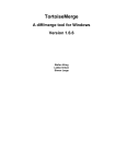
2.
Track Arming Keys
These 48 keys in the upper rows are used exclusively for arming
audio tracks. If pressed while the transport is in Record, the
corresponding track will immediately drop into Record (if it
has a valid input patched to it).
To arm a range of tracks, hold down one key and double click
on another - this will arm the range between them, and disarm
all others. Similarly, double clicking on a single key arms it
exclusively and disarms all others. To force a number of tracks
to enter record at the same time, hold down one of the Track
Arming keys while pressing others. When the last one is
released, all the tracks will enter record together
The Merlin
Bit Depth Key
Soft Menus and Keys
Sets the bit depth for recording
on all current channels, from
16, 20 or 24 bits.
Each disk or transport mode
has a menu of choices which are
activated by the Soft Key
directly below.
Track Selection Keys
These 48 keys in the lower rows are
used for selecting audio tracks for
editing and other purposes. Double
clicking one of the Track Selection
keys causes exclusive selection of
that track. To select a range of
tracks, hold down one key and double
click on another - this will select the
range between the keys, and deselect
all others. The Track Selection keys
are also used to select Location
points within the Project.
Mode Keys
Patch
Each Mode key displays a set of
choices on the LCD screen to the
right. To access a Mode written in
Blue, hold down the Blue key while
pressing the Mode key.
To leave a Mode, simply select another.
Input
Mon
Tempo
BLUE
Space
Gate
Tape
Disab
Export
Preroll
Safe
Setup
Offset
Digi
Nudge
Track
Trim
Razor
Mute
Undo
Disable Key
Arm
Group
Solo
Redo
Project
Name
Edit
Backup
Enter
Used to disable tracks from playback. Differs from muting in that
disabled tracks cannot be immediately switched on, because they are
not being loaded from disk, and
changing the selection of disabled
tracks will cause buffers to be reloaded.
Bit
Depth
GPO
9 Pin
AutoRec
Disk
Gen
Name
Loc
Jump
LTC
Jump
secs
Store
Loc
Vari
Speed
Recall
Loc
Solo and Mute Keys
secs
Record
Here
Play
Again
Record
Again
REC
Hold down key to display soloed or
muted tracks on the Track Keys,
then press them to change selection.
Undo Key
Reverses the most recent edit. Pressing
again reverses the edit before this one,
up to a maximum of 64 levels.
Redo Key
Reimplements the last edit that has
been undone. This can be repeated until
all edits are redone.
Enter Key
Seconds Keys
Used to terminate command sequences
or confirm destructive actions.
Jump Keys
Move the transport to
next or previous Points
(clip starts and ends),
timecode Marks, or by
specified intervals.
Page 8
Transport Controls
Record may be entered by pressing Play and Record together,
or by pressing the Record key
alone. The control for this setting is on the System Page (Type
<Blue-S>).
Move the transport by a
predetermined amount.
Hold Blue and press the
key to set the amount.
Transport Smart Keys
These keys provide special
functions for making recording easier.
User Manual
TM
Console
9-pin Button
Disk Button
Puts a 9-pin machine online, or activates 9-pin slave
mode if selected. Press with
the Blue key to set this machines parameters. Cannot
be activated when the LTC
button is on.
Takes disk recorder on
and off line. While
offline, it will not respond to transport
commands.
Master Time
+ and - Keys
Numeric
Register
Shows
the
timecode position
of the current
master machine.
Used for timecode entry and arithmetic.
Used to increment and decrement the Numeric Register, the
Zoom range, or any selected
parameter in a Soft Menu.
Numeric Keypad
Types numbers into the Numeric Register, the Zoom range, or any selected
parameter on a Soft Menu.
When used with the Blue Key, selects
track displays as follows:
1T
1 track display <Blue-7>
2T
2 track display <Blue-4>
4T
4 track display <Blue-1>
8T
8 track display <Blue-0>
16T
16 track display <Blue-8>
24T
24 track display <Blue-5>
Blue Key
Go To
-
7
16T
5
4T
Cycle
Enter
Bit
Depth
GPO
9 Pin
AutoRec
Jump
3
2
8T
32T
00
0
12T
48T
Recall
Loc
From and To Keys
Play
Again
Used to create ranges for edit operations, and start/ end times for Looping,
Auto Recording etc. Single press and
release means From or To Here. Hold
key down for LCD soft menu items to
appear, press Enter to confirm choice.
SHUT
secs
Record
Here
Subf
Clear
To
From
Zoom
JOG
Store
Loc
Enters zeroes in the Numeric Key Pad,
or in any selected parameter in a Soft
Menu.
When used with the Blue Key, toggles
subframes off and on in the Numeric
Register and all other LCD timecode
displays.
LTC
Jump
secs
1
Clear Key
6
24T
Vari
Speed
Disk
Gen
Name
Loc
9
8
1T
4
Hold down while striking other keys if
item printed in Blue is required.
BLUE
+
Record
Again
REC
Zoom Key
Used to change the time scale across the
video screen. Hold Zoom key down and
turn Jogger Wheel, press + or - or type
a number from 1 (8 hours across the
screen) to 16 (6 frames across)
Jog and Shuttle
Keys
Jogger Wheel
Holding down the Jog key
shows a menu of setup
parameters for jogging.
Gen Button
Enables and disables the timecode
generator.
Used for Zooming, changing
parameter values in Soft
Menus, transport Jog and Shuttle and increasing or decreasing
the Numeric Register timecode.
Alphanumeric Keyboard (not shown)
Location Keys
For storing and recalling
remembered
points within the
Project.
User Manual
LTC Button
Turns on LTC chase. Press
with the Blue key to set this
machines parameters.
Cannot be activated when
the 9-pin button is on.
The alpha keyboard is a separate unit which may be
stowed in a pull-out drawer in the Merlin trolley. It
is used to name disk recorder items (clips, tracks,
projects).
<RETURN> key is also used to clear error messages
from the status line on the video screen (second
from top).
Page 9
TM
3.
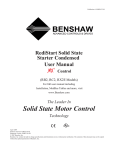
How the Merlin Disk Recorder Works
When we record in Merlin, the audio is turned into digital data and stored on hard disk, together with the other
recordings we have made. It also appears as a clip on the screen, which is a reference to the Master Recording
we just made.
Project 1
Project 2
Project 1
Unused Disk Space
Project 1
1
2
3
4
Project 2
Immediately after our fourth
recording, we can see the Master
Recording on the hard disk, and its
referencing clip on the track where
we went into record. The clip
references the Master Recording
by pointing at the audio to be
played (in this case the whole
Master Recording)
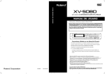
When we edit the audio, we do it
by changing which part of the
Master Recording we are pointing
at. We call these pointers the Head
and Tail of the clip
Project 1
Project 2
Project 1
Unused Disk Space
Project 1
1
2
3
4
Project 2
Here we have split the original clip
so that the first part is on a different track. In fact we now have two
clips which point at different parts
of the Master Recording. On the
first one we have also removed part
of the Tail, which has moved the
Tail pointer to an earlier part of the
audio.
The Head and Tail pointers can be
moved by editing at any time,
allowing us to cut pieces off the
clip, or replace parts that were
previously removed.
A clip can be thought of as an
instruction to the computer to play
a certain Master Recording at a
particular time, within the given
pointers.
Page 10
User Manual
TM
4.
Merlin Screens
There are 10 user screens in the Merlin software. Some take up the top section of the screen and others the lower
part. There are always one upper and one lower display on the screen.
Displays are automatically changed in response to recording, editing and transport control commands, but they can
also be placed on the screen by command. A description of each display follows:
Display Name
Upper/Lower
Key sequence
Arm
Upper
<Blue>A
Automatic Display
AutoRec Menu
The display shows the amount of recording time left in the currently-used disk drive, the length of the currently recording clip, and the input/output meters.
Patch
Lower
<Blue>P
Patch SubMenu
Shows the inputs that are patched to each track, plus the type of input selected.
Track
Lower
<Blue>T
Whenever a
project is open
Shows clips on the tracks with waveforms that scroll when the transport is moved. The number of tracks
shown on the screen can be changed up to 24 by holding down the Blue key and pressing the number keys in
the Numeric Display. These are marked to show the numbers of tracks that will be displayed.
Takes
Upper
<Blue>K
Edit Menu and
others
Shows clip information including mono/stereo, audio level, duration, source file (if borrowed) and layer
number. Where several clips are stacked on top of each other, it is possible to see the top four layers. By
going to the Track Menu you can scroll down to lower layers and lift any clip to the top layer.
File
Lower
<Blue>F
Project menu,
Backup
Displays a list of files on the current storage device, and information about that device.
Device
Upper
<Blue>D
Same as file
Displays a box for each storage device on line (and configured in the mdr_devices file). A fuel guage shows
the available storage on the device in blue, the size of an open file in yellow and the amount of freespace in an
open file in green.
Locations
Upper
<Blue>M
GoTo Location and
Name Location
This display shows a list of Locations in numerical order with their names. Three columns are shown, with the
active column in the centre showing timecode positions of the locations. When the transport is being moved
the locations display scrolls to highlight the latest location passed by the transport.
Waveform
Upper
<Blue>W
The waveform display shows a list of all the Master Recordings in the project. This can be scrolled up and
down using the arrow keys on the alphanumeric keyboard. It is used for recovering clips that have been
accidentally erased. (See Recovering Lost Clips)
System
Lower
<Blue>S
This is used to change system setup parameters including print characteristics, backup device options,
crossfade characteristics and meter scaling. These functions are described in other sections of this manual.
Do not change parameters on this page unless you know what you are doing.
User Manual
Page 11
TM
5.
The Merlin Recording
The Disk Recorder Page is Merlins display medium. It consists of a number of different sub-pages which are automatically changed to suit functions being performed. You can also force the display of a screen that you want by
Disk Light
The Fairlight logo flashes red when
a disk is writing, and blue when it
is reading. During network activity it flashes white.
Time Line
These four lanes are timing graduations
in hours, minutes, seconds and frames.
They expand and contract with changing
Zoom scales. The finer graduations are not
shown unless the Zoom scale gives at least
one pixel for each unit of time in that lane.
Fade
These lines indicate a fade. If the
fade occurs where clips are overlapping, then a crossfade between
the two clips results.
Range Size
In modes that use timecode ranges to
indicate the active editing area, this
field shows the size of the current
range (in timecode units). The pictured mode, Grab, does not use a range.
Selected Track
The track(s) selected for editing (by lighting their
Track Select Keys on the Merlin Console) are
shown with their numbers and track bed in a light
colour.
Unselected Track
Tracks that are not selected for editing
are shown in dark colours. Their Track
Keys are not lit up.
Audio Waveform
Displays a graphic of audio amplitude versus
timecode. The data for this graphic is
generated as the audio is loaded from disk,
just prior to being played. As soon as you
locate the transport to a new place the audio
for that timecode location is loaded, and the
waveforms quickly appear.
Page 12
Selected Clip
The selected clips are shown in red. If
you are working in a Menu with an
editing range, the parts of the clips
inside the range (on selected tracks)
are shown in the same red colour. In
all cases, red indicates that the clip(s)
will be affected by the next edit command.
Cursor
Also known as the Play Head or Now Line.
Indicates the current timecode position of
the disk project. Audio clips play as they pass
this line.
In edit modes without ranges, the clips selected for editing are always the one(s) touching the cursor.
User Manual
TM
and Editing Screen
pressing the Blue Key with certain keys on the Numeric Keypad. Several of the screens are shown or described in the
next five pages.
Zoom range
Shows the Zoom number, from 1 to 16,
of the horizontal scale. Higher numbers
indicate finer display (less time on
screen).
Current Time
This field shows the timecode position of the current disk project.
Takes Screen
Shows information about the clips (pieces of audio)
on the currently selected track. You also see layers of
clips that are underneath and cannot be heard.
This screen is automatically displayed whenever you
enter an editing Menu. You can also force its display
by typing <Blue>k.
4T Screen
Shows four tracks. You can select
this screen by typing <Blue - 4>. The
features of this screen are identical to
those of the 24, 16, 8, 4, 2 and 1-track
displays. They are selected by typing <Blue-5>, <Blue-8>, <Blue-0>,
<Blue-1>, <Blue-4> and <Blue-7>
respectively. Tracks higher than 24
can be shown by selecting any one of
them. This will cause the block containing that track to be displayed.
Track Names
Clip Names
Each clip is named as it is recorded,
and can be renamed in the Name
Menu. These names scroll as the clip
moves across the screen.
User Manual
Unselected Clip
Each track can be named in the Name Menu.
These names are fixed in position on the screen.
Clips must be touching the cursor in
order to be selected (unless a range is
used by the editing mode). In either
case, unselected clips are shown in blue,
and are not affected by editing commands.
Page 13
TM
6.
The Device
Explanation of Terms
Name of the current
open project, if any
(see Starting a Project)
4 Gbyte hard drive
by Seagate, SCSI
address 0
Number of
items in current directory
view.
SCSI ID and
Logical Unit
Number of
current disk.
The
timecode
frame rate for the
project (see Setup
Menu)
Each storage device has a number from 1 to
6 (plus a backup device which may be number
7)
You can name each device when initialising
it if you wish (see Preparing Disk Drives for
Work).
Manufacturer of disk drive
Total size in Megabytes (each megabyte is approximately 10 seconds of mono audio at 44.1
kHz).
Unused disk space in Megabytes
Unused disk space in minutes and seconds of mono audio at 44.1 kHz
Name of domain, or working group of systems.
Name of network node, which may be a
Merlin, MFX or FAME system, a server, or
another computer.
Unit, or hard disk disk drive, attached to system.
Folder or directory on a disk drive.
Projects are named on the Project Menu
or renamed on the Name Menu. The .MT
at the end of the name indicates a
multitrack file or project. Other file
types you may see are .MK files (macro
files) .omf files (OMF export files) WAVE
files and more.
Page 14
User Manual
TM
and File Pages
Complete location or "path
list" of currently selected
file.
Indicates if
the disk is
removable
(e.g. Magneto-Optical drive)
Indicates if
the device is
write protected.
Indicates the device disk
file system. This could be
RBF (the OS-9 file system), FLFS or MDR-DOS
(proprietary Fairlight file
systems) or NTFS (Windows NT file system, only
on servers or other PCs)
Sample rate of audio
in current project (see
Arm Menu)
The Device Page
This page shows information about the storage devices attached to the currently selected
node (machine). The page is automatically
displayed whenever you open or close a project,
or begin a file copy or backup procedure. You
can also force its display at any time by typing
<Blue>D.
The File Page
This page is split into sections showing the
network structure in which machines are placed,
and information about one of the storage devices, including the files it contains. One file is
highlighted, making it ready for opening, copying, or whatever function you have in mind. You
may scroll the highlighted bar up and down the
screen, choosing a file to be acted on by the next
command.
This display is shown whenever you are opening a file, deleting etc. You can force its display
at any time by typing <Blue>F.
Shows the last date
on which the file
was altered.
User Manual
Size of files (given in hours,
minutes and seconds for
Merlin Project files - those
with suffix .MT)
Shows the sampling rate of the
audio in the file.
Page 15
TM
7.
The Patch and Meters Display
The Patch Display shows all the information about which input is patched to which track, and what choices have
been made on each of the inputs.
This display is shown whenever the Patch Menu is selected. You can also force its display at any time by typing
<Blue>P.
The Meters show you the audio level at each output. It is automatically displayed whenever you enter the Arm
menu, and you may force its display at any time by typing <Blue>A.
Twenty Four
Track Meters
This display shows the output levels of every physical output of the
system. Whenever a track is armed,
the meter shows you the input to
that track. Small red rectangles indicate the input(s) patched to each
track. When a track is playing a
stereo clip, the right side of the clip
appears on the next highest output, and the meters show this.
Selecting a track above 24 causes
a second bank of meters to be displayed.
Patch Display
This display shows you the
inputs which are patched to
each track, as well as the type of
input selected and the gain setting for each input.
List of tracks by name.
When you first create a
project these will be named
Track 1, Track2 etc,
but you can give them your
own names using the Name
Menu.
Grid showing the input(s)
patched to each track. Note
that the same input can be
patched to many tracks, but
only one of them can be in
record at a time.
When two inputs are patched
to the same track, it means that
stereo clips will be created when
the track goes into record.
Shows the gain currently applied to
each input.
This track has been
selected so that its inputs can be changed. It
is possible to select any
number of tracks for
this purpose. Note that
the inputs that are
currrently patched to
this track are also selected.
List of inputs,
numbered 1 to 24.
Grid showing the type of
input selected, out of
ANLG -10, ANLG +4,
AES/EBU or SP-DIF.
Note:
To change the settings for an input, you must open the Patch Menu, and
then choose a Track which has that input patched to itself. There is no
direct way to choose a particular input.
Page 16
User Manual
TM
8.
The LCD Display
The LCD Display is used to show parameters and timecodes whenever Merlin is being used. The Soft Keys just
below the LCD screen are used to perform the majority of setup and editing functions in the system.
Mode Keys are used to choose a menu in the LCD, then the Soft Keys are used to set parameters and execute
commands.
Arm
Group
Patch
Tempo
Input
Mon
BLUE
Preroll
Space
Gate
Tape
Offset
Project
Disab
Export
Level
Backup
Safe
Setup
Fade
Digi
Mute
Solo
Nudge
Track
Trim
Razor
Undo
Redo
Name
Edit
Enter
A bank of switches, with the current Mode highlighted.
Master Timecode Position
Numeric Register
00:01:04:04.33
00:02:52:05.00
Sync
Int
Inp Sync
OFF
Rate
44100
Stereo
OFF
Pad
0 dB
The LCD Menu, showing soft key labels associated with the current Mode.
User Manual
Page 17
TM
9.
Starting a Project
A piece of work on Merlin is called a Project. When you wish to begin recording a Project must be open.
By pressing the Project key you can see the directory of files in the system, and access file management functions.
The Directory
The Directory is arranged in a hierarchy as follows:
Domain
-
a network group, consisting of servers and clients.
Node
a machine on the network, which could be a server, a Fairlight machine (Merlin, MFX or FAME)
or another computer.
Unit
-
a SCSI storage device (hard disk, magneto-optical platter or tape drive).
Folder
-
a directory on a disk. Folders may be nested to many levels inside each other.
File
-
a Project file or other useful file in the system.
Domain
Node
Unit
Folder
File
Folder can be
expanded
(press ENTER)
From and To Keys
Move focus between Folder
View and File View
Folder view
On the left side of the screen, the hierarchy of items, other than Files, is
shown in a descending indented structure. From an operational point
of view, Domain, Nodes, Units and Folders are seen in the same way,
except that only Folders can be created, deleted and renamed. Henceforth the term Folders will be used to indicate any of these levels in the
hierarchy. A Folder containing other Folders is shown with a + sign.
File view
On the right side of the screen, one level
in the hierarchy is shown in a vertical
list. This level may contain Folders and
Files, which are contained in one
highlighted Folder on the left side of the
screen.
Navigation
At any time while browsing the Directory, there is a current navigation point where a file or folder is highlighted. This
point may be in the Folder view or the File view.
To cross from the File side to the Folder side and vice versa, press the From and To keys.
To move the navigation point up or down the screen, use the + and - keys, or the Jogger Wheel.
To open a Folder and reveal the other Folders and Files inside it, press <Blue +> or Jump Right.
To retract all Files and sub-Folders under a Folder, press <Blue -> or Jump Left.
To select the next/previous Node on the network, press <ctrl +> / <ctrl ->
To select the next/previous Unit on any node, press <shift +> / <shift ->
To open a File, press the Enter key. This can only be done in the File view.
Page 18
User Manual
TM
Notes:
1.
The operation of keys in this interface is very similar to that of Windows.
2.
There is no way to open a File other than by pressing the Enter key.
3.
Locked files have an L indication. This usually means that another user has the file open.
4.
Any navigation moves done with the plus and minus keys e.g. <ctrl +>, can also be done with the Jogger
Wheel. For example, holding down the Blue key and turning the Jogger Wheel anticlockwise will open the entire
directory "tree" for the network.
The Project menu
All file operations other than opening are done by moving the navigation point to a Folder or File and then pressing
a Soft Key in this menu. When there is no file open, the menu looks like this:
Space
Project
Project
new
The first step in any project. You will be prompted for
a name before you can continue, so type one of up to
15 characters. The current device number is displayed
in the upper LCD, and you can change it using the
Numeric Keypad if you wish to start your new project
on a different device. Press ENTER to create the new
project. If there is a project open when you press this
key, it will be closed before the new one is opened. Note:
names should contain only the following characters:
delete
be prompted for confirmation, and in the case of a
Folder, you will be
prompted again if the Folder
contains Files.
Press this key to access
other functions. See next
more
page
More
A - Z, a - z, 0 -9, _ (underscore)
Although Merlin will allow entry of some other
characters, you are advised NOT to use them, as
they may cause problems in exchange with other
computer systems.
Press this Soft Key to delete a File or Folder. You will
User Manual
Page 19
TM
Project Menu Options
Space
Project
Project
new
folder
copy
Creates a new Folder underneath the
currently selected one (i.e. the one where
the Navigation Point is). You must supply a name for the new Folder, then press
Enter.
Initiates the copy sequence. First you must select
the destination directory for the copy by browsing
and pressing the Okay Soft Key. (If required you
may create a New Folder by pressing this Soft Key,
typing a name and pressing Enter. Then open it by
browsing and press Okay to make it the destination
Folder.) Now you must supply a name for the copy
by editing the one in the upper LCD. Press ENTER
to start the copy. Note that if the machine you are
copying from or to is in Play at the time, the copy will
be held off until the machine stops, and will be held
off again each time the machine goes into Play.
Page 20
move
rename
The Move sequence is
exactly the same as the
Copy sequence, except
that the original file is
removed. If the destination Folder is on the
same storage device as
the File, the Move
command takes only a
few seconds, regardless of File size.
back
Goes back to the first
level of the Project
Menu
Allows any File or Folder to be
renamed. Edit the current name
in the upper LCD and press
Enter. Domains, Nodes and
Units cannot be renamed here,
and the currently open Project
can only be renamed in the
Name Menu.
User Manual
TM
When a Project is open, the Project menu looks like this:
Space
Project
Project
close
extend
password
delete
more
This removes the open project
from view, saving it first.
This makes a copy of the open project, but accesses all of the audio
data from the original file. This is used to extend a file to another
project or disk drive when you have filled the one you are on, or
to make a copy of the edit list so you can try radical changes. The
command syntax is exactly the same as for Copy. Extend takes only
a few seconds and opens the extension file after creating it. See
below for more information.
Automatic Project Extension
Press this Soft Key to set or change the password of the currently open file. A dialog appears, requesting a password to be entered,
then asking for confirmation. After this the
cursor moves to a panel allowing the public
access of the file to be set. See below for details
on public access. To remove an existing password, enter a blank box in the password dialog
box.
Merlin Project files have a maximum size of 4 Gigabytes. If this limit is reached while recording is in progress, the file
is automatically extended. This is hardly noticeable when it happens, but will cause a split in the clips that are
currently recording.
Once a file has been extended, all the audio data from the original or "parent" file is in read-only mode, and therefore
cannot be destructively over-recorded in Tape Mode. If this is attempted, recordings will be made instead of the old
ones being replaced. Editing of extended audio is, however, unrestricted, because this is a non-destructive process.
Automatic extension can be switched off on the Setup (Blue-S) page.
Password Protection
Any Merlin project may have a password which restricts access to the material. When there is no password, one can
be applied by anyone who opens the file. There are three levels of access available to a file with a password, one of
which must be chosen when the password is created. These are:
Public
-
any user can open the file and change any part of it. A password is not requested upon
opening the file.
Read Only
-
any user can open the file and play the audio, but cannot change anything. A password
is requested when first opening the file, and if none is supplied, read-only permission is
granted. Extending the file will then create a new unpassworded file extension, which can
be edited as required without changing the original file. If the correct password is
supplied when opening the file, then full write, delete, rename and move permission is
granted.
Private
-
no user can open the file at all, without supplying the correct password.
Notes:
1.
Even a file which has Public Write access cannot be deleted, renamed, or moved. Any attempt to perform
these operations will result in the system requesting a password.
2.
Once you have opened a file using its password, all other projects with the same password will be opened
without the machine requesting you to supply the password again. This may apply to several passwords that
have been used in a single session on the machine, and the only way to make the machine "forget" these
passwords is to restart it.
User Manual
Page 21
TM
Access Modes - Levels of Openness
Merlin operates in a networking environment and therefore must prevent conflicts between users which could compromise the integrity of file data. To do this it defines five different access modes, which are listed below in order of ascending openness.
Media Read
At this level, only the audio data from a Project is being read, and nothing is being modified. When audio clips are
borrowed from other Projects (see Importing for details), the borrowed-from Project is first opened for Project Read
(see below) in order to check the file headers and other information that guarantee the project integrity, and is then
dropped back to Media Read. A project open for Media Read has a book-like icon on the File Page display, representing
it as a Library.
Project Read
At this level, the header information is being read, and nothing is being modified. No other user may modify the project
while it is in this state. Project Read occurs on first opening a file for import, and on first re-attaching a Project when
opening another Project which borrows from it. In both these cases, as soon as the header information has been read,
the Project is dropped back to Media Read.
Marked for Backup
When a Project is marked for backup it is at the same level as Project Read, because the header information is backed up
along with the audio data. The Project remains at this level throughout the backup, except at the end when it is briefly
raised to Append Write (see below) in order to change the Last Backup date.
Append Write
When a Project is open for recording and editing, audio is normally being appended to the file rather than removed.
Although the edit list may be constantly changed in the most destructive ways, the audio data and the Project header
information which describes it are generally added to but not changed. This means other Projects which depend on the
integrity of that information are not affected.
Modify Write
Only a few operations have the ability to change existing audio data or audio header information. These include
Overwrite recording, Commit, Dispose and Pack. Project Status is raised to Modify Write only during these operations. If
another user has the Project open, permission for Modify Write is not granted, and the operation cannot proceed.
Multi-User File Access
This section contains information relating to network clients which may not be Merlins - they may be MFX or FAME
products instead. Some of the actions described here are not available in Merlin software, but the information may be
useful to understand the network directory screen, which can be affected by any client on the network.
In a network, many users may have access to the same files, and sometimes they will want to work with them at the same
time. The following chart shows which access modes may co-exist.
Access Mode
Coexists With
Modify Write
None
Append Write
Media Read only©
Marked for Backup
Media Read only
Project Read
Media Read only
Media Read
Append Write, Backup, Project Read, Media Read
Media Reads may co-exist in any number, meaning that a Project may sustain, for example, any number of users at Media
Read level (i.e. borrowing clips from it) and also one user at up to Append Write level, who may be recording and
editing. If any user is currently attached to the Project by borrowing, the user who is editing it will not be able to perform
overwrite recording, committing etc.
Another constraint is that, in order to initiate a Media Read, a user must first pass briefly through Project Read in order
to check the header information. This cannot be done while another user has the Project open for Append Write, since
the second user might be changing the header information at the very moment that the first one is reading it. So, if a user
is editing a Project, no one else can attach to it, although any users who were already attached to it before it was opened
for editing will be able to maintain their attachments.
The action of opening a Project for Import also causes it to briefly enter Project Read, even if it has already been opened
and closed previously during this session. This means that if another user has opened the Project for editing since the
first time it was opened for Import, it will not be able to be opened for Import again. (Import is not available in the first
Merlin software release.)
Page 22
User Manual
TM
The Clip
What you are creating when you record is called a Master Recording (you could be creating up to 24 at a time). It
starts when you drop into record, and it ends when you drop out. You are also creating clips which are displayed on
the tracks you are recording. Each clip is a reference to the Master Recording, instructing the computer to play it at
that timecode and out of that output.
Later you may edit this clip, and this will be fully described in the section Editing.
Time Code Reference
Each clip has a time code reference built into it that causes it to remember the right time to play. Unlike a tape
machine, which must record all of the silence in between the useful audio, Merlin only stores the useful audio, and
the time that it should be played.
Overlapping Clips
You can record many clips on the same track, even if they overlap. The track can only play one clip at a time, however, and this will be the most recent one you recorded or copied to any piece of track (during crossfades the top
layer and the next one down are both played). It is useful to think of the clips as being stacked on top of each other
as they are recorded, with only the topmost one being visible to the tape head. This is illustrated below.
Clips are recorded or pasted on top of earlier clips. We hear only the top layer (white portions).
The same group after one clip has been trimmed, revealing the audio underneath.
The Track
A track in Merlin behaves something like that on a tape recorder. But it is not the same. A track is simply a piece of
time on to which you may record or paste clips. All the clips on a track go to the same output.
The Current Track
Throughout this manual reference is made to Current Track(s). They are the ones you have selected for recording
or editing. Selecting tracks for any purpose is always done on the Track Select Keys (except for arming them), and
the last one you selected is a special Current Track which has a higher priority than the other selected tracks. The
video screen changes when necessary to show the group of tracks that includes the current track. Selected tracks are
shown with their numbers and backgrounds in lighter colours than unselected tracks.
User Manual
Page 23
TM
10.
Recording
Setup for recording is controlled by two menus and a toggle. The Patch Menu connects inputs with tracks, while the
Tape Mode Menu (accessed by holding down the Blue Key while pressing the Tape Mode key) allows critical
recording parameters to be set. The Tape Mode switch itself toggles between destructive (Tape) and non-destructive
(New) recording modes which are described below.
Selecting Tracks for Recording
Making a track ready for recording is called "Arming" the track. Merlin's upper row of Track keys is dedicated to this
purpose. A track can always be armed, as long is it has an input patched to it. To see the patching setup, and
change it, use the Patch menu, described below.
Recording Modes
The Tape Mode switch toggles between destructive (Tape Mode) and non-destructive (New Mode) recording.
NewMode
When the Tape Mode switch is OFF, Merlin records in New Mode, which has the following properties:
Whenever Merlin enters record, a new Master Recording is created for every armed track.
If there are clips already on the track, the new material forms clips that are placed "on top" of the existing clips. Later
the Track Menu can be used to bring the lower clips to the surface.
New Mode is mistake-proof - going into record over the top of existing material does not damage it in any way. It is
also very useful for recording multiple takes of the same performance eg. while recording instrumental overdubs or
alternative ADR lines, because there is no need to change recording tracks in order to preserve a good take.
TapeMode
When the Tape Mode switch is ON and illuminated bright red, Merlin records in Tape Mode, which has the following
properties:
When TAPE mode is selected the recording process chooses, for each track, whether to create a new recording or
replace an existing one, depending on the situation where record is entered. If recording is commenced where the
track is empty of clips, a new Master Recording is created. If recording commences where there is an existing clip, its
Master Recording is overwritten, subject to these rules:- overwriting can only occur if the material already on the
track is the same bit-depth as the current setting for recording, and if the existing material and the recording setup are
either both Mono or both Stereo.
Overwriting means directly replacing the recorded data on the hard disk. This cannot be reversed in any way, so if
Recording is commenced at the wrong place, a permanent mistake is made. On the positive side, while overwriting is
occuring, no disk space is being consumed, because we are replacing what already exists on disk.
Material that has been imported into the project (borrowed) or material from earlier versions of the project that have
been extended cannot be overwritten, because the media is actually in another file.
If, while overwriting the material in a clip, the transport reaches the end of that clip, it will be extended, but only if the
clip has not been trimmed at the tail. (This rule prevents Merlin from overwriting audio that is not visible on screen,
which is considered too dangerous.) If the clip's tail has been trimmed, a new clip and Master recording will be
started when the tail is reached.
Once a Tape Mode recording begins, it erases all clips or parts of clips in its path, except the clip, if any, that it is
replacing. So, after a Tape Mode recording, the range of time just recorded will have no "layers" of clips, only the
one that has just been recorded.
Tape Mode is used when it is desirable to save disk space, when a simple edit structure with no layers is desired, and
when Merlin is being controlled by an external source such as a mixing console. The reason for this last item is that, if
many passes through approximately (not exactly) the same range of time are performed, the clips created by New
Mode would result in many tiny pieces being played, which is not only confusing, but can affect disk bandwidth
adversely.
Page 24
User Manual
TM
Monitoring of Armed Tracks
When tracks are armed, you have a choice of listening to their input (source) or their playback (track). To control the
monitoring function, use the Input Mon button.
Input
Input
Mon
Mon
When Input Mon is toggled ON, the armed tracks play their input (source) all the time, except when the transport is
in Jog.
When Input Mon is OFF, the armed tracks play their playback (track) when the transport is in Play or Jog, but play
their input for all other transport modes.
All unarmed tracks are in repro or track mode, all the time.
User Manual
Page 25
TM
The Patch Menu
The Patch Menu is used to choose inputs for the tracks, as well as the type and gain of each input. In this submenu,
the Track Keys are first used to select which tracks are having their inputs patched. Once the {patch} or {group}
button has been pressed, the Track Keys are used to patch inputs to the selected tracks.
patch
Patch
Patch
Press to patch inputs to selected tracks. Track
keys will flash, indicating that they now represent
inputs. The ANALOG/DIGITAL toggle becomes
active, allowing either type of input to be selected.
Press one key to patch that input to all selected
tracks, or any two keys together to patch stereo
inputs. Releasing the keys makes the patch and
returns the Track Keys to selecting tracks.
group
Gain
dB
Press to change the gain on the inputs to
the selected tracks. This can be done with
the Jogger Wheel, the + and - keys, or the
Numeric Keypad. If you want to type a
negative value, press the <Clear> key, then
<minus>, and then the number.
Press to assign multiple inputs to multiple tracks (in mono only). The tracks are
selected before pressing this Soft Key. All the Track Keys flash, indicating that
they represent inputs. Any number of inputs can be selected simultaneously, and
upon release they are patched sequentially to the selected tracks. If there are more
tracks than inputs, the inputs wrap around to the beginning again, allowing
multiple sets of the same inputs to be patched to multiple tracks.
Analog/Digital
Whenever the patch or group commands are issued, the 4th and 5th Soft Keys change to
allow a choice between Analaog and Digital inputs. Only one type at a time can be patched,
so choose the appropriate one before making a choice of inputs using the track keys.
Mono/Stereo
This is not selected explicitly, but is simply determined by the number of inputs patched to
the track. When two inputs are patched to a track it will automatically record stereo clips. It is
possible to have some tracks patched for mono recording and others patched for stereo. It is
even possible to patch an input to one track in mono, and as part of a stereo pair on another
track (though they cannot be armed at the same time).
In the disk recorder, a stereo pair has the following properties as distinct from any pair of
mono tracks:
1. Editing is always performed on both sides at once.
2. The output numbers are always a consecutive pair.
3. If a clip overlaps a stereo clip on the preceeding track, the right hand side of the stereo
clip is not heard.
Page 26
User Manual
TM
Gain Structure
1. To get Unity Gain through the system with Analog inputs, set Gain to zero and set Type
to Analog +4.
2. The maximum analog input level with Unity Gain is +24 dBu. More than this will cause
overload of the Analog to Digital Converter. If your audio source is lined up to give +4dBu
output at 0 VU, this will correspond to -18 on the meters of Merlin. Maximum output level is
also +24 dBu, which occurs when the waveform amplitude is at maximum (0 dB on the Merlin
meters). This level may be changed. Please refer to the Installation Manual, or see your
Fairlight distributor if you want to do this.
3. To get Unity Gain through the system with Digital inputs, set Gain to zero and Type to
AES/EBU.
4. The Gain field causes boost or cut of the input signal, in the same domain (digital or
analog) as that signal.
Arming Restrictions
Sometimes Arming a track disarms another track. This occurs when there is already a track
armed that is patched to the same input .
Repatching
It is not possible to repatch an input to a track while the track is in record.
The Tape Mode Menu
While the TAPE Mode menu is active, the Track Keys can be used to arm and disarm the tracks.
Tape
Tape
Handle
0 fr
A "handle" is extra audio at the start
of the recording. This may be set up
to 30 frames, and it causes Merlin to
enter record earlier than you tell it to.
For this to work, the track must have
been armed for at least the length of
time corresponding to the handle
length. The extra audio does not
appear in the clip created immediately after the recording, but may be
uncovered using the Trim Head
command in the Trim Menu.
User Manual
Page 27
TM
Notes:
Arm Many Tracks
Any number of tracks can be armed at the same time.
You may patch one input to as many tracks as you like, but only one track at a time can
record or monitor it. If a track is armed, and you try to arm another one patched to the
same input, the new choice will replace the old one. This is true even if Merlin is in
Record, where recording will end on the originally armed track, and continue at the next
audio sample on the new track.
Arm on the Fly
It is possible to arm tracks while the system is in record. The track goes into record
immediately, as long as it has a patched input.
Handle in Tape Mode
Handles are only created when recording new material, not when overwriting old
material. In Tape mode this will depend whether any audio is present at the punch-in
point.
Metering Input Levels
The input levels to the armed tracks are shown as vertical bargraphs at the top of the screen. These are seen on the
Video Display whenever the default AutoRecord menu is displayed. For tracks that are not armed for record, meters
show the playback levels. The behaviour of the meters can be changed so that the background colour changes to
warn you when a certain input level has been reached. This is done by setting the METER RED LEVEL field on the
System Page (type <Blue>S, then use the mouse to change the value of RED, or type RED level<RETURN>, where
level is the desired audio level, with or without a minus sign.)
The meter scaling can also be changed. This is done by setting the METER LAW, which affects the range of the
meter and its linearity. Meter LAW can be changed on the System Page (type Blue-S), or by typing LAW
n<RETURN>, where n is a number from 1 to 6.
Entering Record
Using the Merlin Record Button
With the setup for recording complete, start recording by pressing the Play and Record buttons at the same time.
Merlin will not enter record until it has locked to the synchronising signals in the system. This takes a short time after
entering Play, longer if you are running in sync with a video machine. If you try to enter record earlier than the
system is ready, it will automatically delay the onset of recording until locked. If the system is in Play when the
Record command is issued, recording is immediate.
While in record mode, individual tracks can be placed in and out of record by arming and disarming them, using the
Track Arming Keys.
Timecode Track?
It is not necessary to record a timecode track on the Merlin. It stays in sync with the machine controller by counting
the samples of recorded audio that are played and comparing this with the amount of elapsed time since play started.
Playback
Use the Play button to hear what you have recorded. All the tracks will play, except armed tracks if Monitor is set to
Source.
Punch-in Punch-out
While playing, start recording by pressing the Record and Play buttons together. To drop out of Record, press the
Play, Stop, Jog, Rewind or Fast Forward buttons. You may punch in and out at any time while the transport is
moving.
On the armed tracks, if Monitor is set to TRACK, monitoring switches from recorded material to track inputs as you
enter Record, and back to recorded material when you punch out.
Automatic Drop-in
Pre-determined Drop-in and Drop-out points may be activated using the AutoRec menu. This is described later in
this manual.
Page 28
User Manual
TM
The Digi Menu
The Digi Menu is used to choose the source of Master Clock synchronisation, and to switch on Stereo mixing within
the system.
The Master Clock
A digital audio system needs a Master clock to determine the precise moments at which audio samples enter and leave
the system. When transferring samples directly between two systems using the AES/EBU inputs and outputs, it is
necessary to synchronise the Master Clocks of the two systems. Merlin provides a number of synchronisation inputs,
and the Digi menu is used to choose which one of them will be used.
Backup
Digi
Digi
Sync
Int
Selects the source for Master
Sample clock synchronisation.
Includes Internal (crystal
sync), AES/EBU, Word Clock,
Video and Input. This last
choice allows you to choose
one track, whose digital input
will be used as the source for
House Sync.
When switched to AUTO,
finds the lowest numbered
armed track with a digital input
(if any), and selects it as the
sync source. This means that
sync may change if different
tracks are armed. When
switched to OFF, the normal
Sync source, as defined by
the Sync Soft Key, is used.
User Manual
Inp Sync
OFF
Rate
44100
Stereo
OFF
Chooses the sample rate
of the project. Cannot be
changed after the first audio has been put into the
project, by recording or
by importing from another
project.
When switched on,
causes all tracks to be
mixed to stereo, and sent
to outputs 1 and 2. In
this mode, levels and
panning of the tracks is
determined on the Level
Menu.
Pad
0 dB
Allows the audio level
of all outputs to be reduced or increased in
the digital domain. In
some cases this will result in reduced audio
resolution. Merlin
stores a separate setting for the pad when
Stereo Mix is ON so
that it is not necessary
to change the Pad
every time Stereo is
turned ON or OFF.
Page 29
TM
Naming
The Name Menu is used to give names to clips, tracks or the whole Project. Clips can also be automatically named.
Press the NAME Mode key. The LCD gives you a menu as follows:
Name
Name
Edit
project
track
clip
seedname
Rename the currently
loaded project by pressing this Soft Key, then typing a name of up to 18
characters and pressing
the ENTER key
Name the currently highlighted
track by typing a name up to 15
characters and pressing ENTER.
You can then choose another
Track Key and type its name and
ENTER
The clip to be named is the one on the
current track, positioned under the cursor (it will be coloured red). Press Soft
Key, then type a name up to 24 characters and press ENTER. You may then
move immediately on to another clip
and name it.If a range exists, all the
clips within it will be named with one
command.
TRACK
GLOBAL
Toggles between
Global and Trackbased autonaming.
See below for details.
The seedname is used as the
beginning of an automatic
name. A number will be appended to this name, and
incremented each time a new
clip is recorded. See below
for more details
Use of Ranges
If a range has been created, all clips that are wholly inside it can be named with one command.
Keyboard Use
As soon as you press one of the naming Soft Keys, the current name of the thing you have selected will be shown in the
upper LCD. This allows you to use it again, or copy it to another item. You can use the Backspace key to erase the last
character, or the del key to erase the whole name.
Having pressed the clip Soft Key, it stays armed, so as soon as you move the transport over another clip, you can
enter the name into it, perhaps after changing one or two characters. This applies to the track Soft Key also.
Automatic Naming
When new clips are created by recording, they are given a name automatically. This consists of the seedname set in the
Name Menu above, plus a number, which is incremented by one each time a clip is created. When creating the seedname,
you can add a number at the end, and it will be taken as the starting number to be incremented.
If there is no seedname set, new clips are given a number only.
If you select the TRACK toggle, it is possible to set a seedname for each track. As long as TRACK remains selected, the
track seedname will be used when recording on any track which has one. The GLOBAL seedname is used whenever the
toggle is set to GLOBAL, or when you have not set a seedname for the track in record.
Legal Characters
Use only the following characters in names:
A - Z, a - z, 0 - 9, _ (underscore)
Page 30
User Manual
TM
11.
Solo, Mute, Disable and Safe
Disk Recorder tracks can be soloed and muted from the Merlin console.
To choose which tracks are to be soloed or muted, hold down the SOLO or MUTE key, and use the Track Keys to
make your selection. Disabled tracks (see below) will flash, indicating that they are not available for soloing or
muting. When you release the Solo or Mute key, Merlin will return to the Mode you were in previously.
For example, hold down the SOLO button and select Tracks 3 and 4. They are soloed. Release the SOLO key, and its
LED will flash, indicating that the Disk Recorder has tracks SOLOED.
If you prefer, press and release the Solo or Mute key, and that mode will be latched. Then you can make your
selections at leisure before selecting another editing or transport mode.
You can toggle the soloed or muted tracks on or off using the first Soft Key, as shown. When you toggle the key
back ON, the Merlin remembers which tracks were selected before.
Note: Selecting a track for Muting or Soloing does not make it the current track.
Disab
Disab
Export
Safe
Safe
Setup
ON
OFF
Mute
Mute
FOLLOW
ON
Solo
Solo
Toggles Solo or Mute on
or off, preserving the selection of tracks.
Causes tracks that
are selected in any
editing menu to be
soloed.
Track Safe
It is possible to make a track safe, so that nothing on it can be moved, nor can anything be added to the track by
recording or editing. To make a track Safe, press the Safe key and select the tracks to be made safe, using their Track
Select keys (not their arming keys). The arming key will be illuminated in yellow while the track is safe. Pressing the
Track Select key again toggles the track unsafe.
Note that, even when a track is safe, it can be selected for editing, but only copying FROM the track TO the clipboard, ready for pasting on other tracks, is allowed.
Disabling Tracks
Disk Recorder tracks can be disabled from playback. This differs from muting them in that the audio data from
disabled tracks is not fetched from the disk. It is though those tracks do not exist. This can be useful because you
can place clips on disabled tracks, providing extra storage or virtual tracks that are not played.
When you re-enable tracks, there is a delay of a second or two while they are reloaded.
To disable tracks, hold down the Blue key while pressing MUTE. Then the currently enabled tracks will be lit up, and
the disabled ones will be flashing. You may now toggle the status of any track. Double pressing any track key will
make it the only enabled track. Holding down one Track key and double clicking on another will fill in the tracks
between.
User Manual
Page 31
TM
12.
Editing
The Clip
Editing in Merlin is achieved by performing operations on Clips. First we will explain the way a clip is structured.
A clip is born when we record or by being copied from another clip. It contains information about the following:
Master Recording Number
This is a piece of audio stored on disk. It is never altered by editing.
A clip plays by referencing part (or all) of a Master Recording. Many different clips may access one Master
Recording.
The process of editing may change which part of the Master Recording is accessed by the clip, or at what timecode
this happens, but does not change the Master Recording at all.
Head
The Head is a pointer to the first part of the Master Recording that the clip plays. Immediately after recording, the
Head will be at the Start of the Master Recording. By editing you can move it elsewhere.
Tail
The Tail is a pointer to the last part of the Master Recording that the clip plays.
Master Recording
Clip
Start
Not Heard
Heard
Not Heard
Head
Tail
Possible
Sync Point
Fade-In Point
End
Fade-Out Point
Sync Point
The Sync Point of the clip is a point that you can place anywhere in the clip. It is usually chosen as the clearest
moment of the audio that you can use to check whether it is in sync. For example it might be a particularly loud crash
in a sequence of smashing plates. Until you set a Sync Point in a clip, it is at the Head of the clip.
The Sync Point can be found by jumping to points (see Jump keys).
Timecode Reference
The clip is played at a predetermined timecode, and this is stored in the clip.
Fade
Every clip contains a fade-in and a fade-out. By default these are of zero length, so the clip reaches its maximum level
right at the start. But you can set fade points in the clip so that the level is ramped up from silence at the Head to
maximum at the Fade-In Point, and from maximum at the Fade-Out Point to silence at the Tail.
Page 32
User Manual
TM
When clips overlap, the Fades become Crossfades.
Level
Every clip has an audio level. After fading in and before fading out, the clip plays at this level. While the clip is
fading, the effects of the fades are added to the level.
EQ
Every clip has a 4 band equaliser built in to its structure. Merlin plays existing EQ settings created in MFX files, but
has no way of changing them.
Name
A clip may have a name up to 24 characters long. This is given to it in the Name Menu. Many clips can have the
same name.
Project Layer
Each clip occupies a unique layer which is used to determine which clip will overlap when two enter the same
timecode and track. The layers are assigned chronologically, so the most recently created clips have the highest
numbers.
Summary of Editing Commands
All editing is achieved by altering clip parameters as follows:
Editing Menu
Edit
Command Name
Editing Action
Cut clip
Removes selected clip(s), places a copy of them on the clipboard, ready for pasting
Cut head or tail
Moves head or tail pointer to reduce the size of the clip, places
the removed piece on the clipboard
Copy
As in cut, but pointers to original clip are unchanged
Enter key
Places a copy of the edit clipboard at the current timecode
position, on the top project layer.
Trim
Trim
Move head or tail pointer
Fade
Fade Head or Tail
Moves fade in or fade out point
Level
Level Set or Trim
Change clip audio level
Nudge
any
Change timecode reference
Track
Pop
Change project layer
Razor
any
Cut time out or insert time into Project
Selecting Clips for Editing
When you edit, only clips on the selected track(s) will be affected. The clips (or parts) that can be changed are
always shown in red.
To select the tracks you want, use the Track Select Keys, not the Track Arming Keys. The selected ones will be lit.
The clips on the selected track that are affected are chosen in two ways:
1.
On some menus the clip(s) that are touching the cursor are the ones that will be affected by the commands you
issue. This is true on the Trim and Track menus.
2.
Some menus require you to construct a range between two timecodes, inside which the audio is affected. This
is done using the FROM and TO keys. The Razor menu uses a range. Many menus work with or without a
range, such as the Edit Menu.
User Manual
Page 33
TM
13.
Timecode Ranges
Merlin allows two methods of choosing what to edit. One mode is called clip or object-based editing, and the other is
called range or timecode-based editing. Some editing menus, such as Grab, work only in clip mode, while others, such
as Block, work only in range mode. Many menus can work in either mode, sometimes with slightly different commands for each.
There are also two range modes, part mode, where any parts of clips included in the range will be affected by edit
commands, and whole mode, where only clips entirely inside the range will be affected. Any editing menu will use
only one of these modes. The redness of the clips always shows what will be affected.
Setting up a Range
A Range is the span between two timecode numbers. When using a Range for editing, only audio between the two
timecodes is affected. The Range keys (From and To) are used for setting ranges.
Simple Method
To set a Range, press and release the FROM/TO keys at the start/end of the Range you wish to edit. If there is no
range at the moment, you may press just one of these keys and use the Jogger Wheel to drag out a range. You may
issue edit commands at any time while dragging out a range.
Using Range Menus
(The following description applies equally to the To key.) Holding down the From key causes a menu to appear,
described below. At the same time the graphics show the existence of a range with its end at the cursor. Pressing the
Soft Keys affects the range end position as follows:
From
From
time
Pressing this Soft key latches
the Menu (you can let go of
the From Key), and adopts
the time in the Numeric Register as the range start. You
can now type in or edit a
timecode number and press
ENTER. For details on editing Timecodes, see Entering
Timecode Values.
Pressing this Soft Key
latches the menu, adopting
the current Location as the
range start. You may now
type in a Location number
or select one with the Jogger Wheel or + and - leys,
and press ENTER.
Page 34
loc
last
prev
gap
project
head
This Soft Key does not latch the
menu. The time of the Project
Head (i.e. Mark 0) is adopted as
the Range Start, and you have the
same options as for the {prev
gap} Soft Key.
This has the same effect as pressing the
{time} Soft Key, except that the previous
Range end (from before entering the
menu) will be adopted.
Now it can be edited
in the usual ways, before pressing ENTER.
This Soft Key does not latch the menu. The From Menu "finds" the
nearest previous moment of silence between clips on the current track,
and adopts it as the Range start. At this point you can press other keys
to continue moving the Range start:
Release the From Key at any time to accept the current Range start;
Press the {prev gap} Soft Key again to find a further previous gap;
Press any other Soft Key and switch to its functions. If this latches the
menu, the ENTER key will be needed to complete the sequence;
Press either Jump Key to move the Range start.
User Manual
TM
From Point
Cursor
To Point
While a Range Menu is latched:
1.
You can use the Jogger Wheel to move the end of the Range.
2.
You can use the Jump keys to move the end of the Range
3.
The video display highlights the Range that will be created if you press ENTER
4.
The Numeric Register shows the current value of the Range end that is being changed
5.
Pressing ENTER establishes the range and takes the system back to the previous editing mode.
Shortcut to Range Setting
The Track Keys can be used to set range ends very quickly using the following key sequence:
<From - TrackKey> - hold down the From key and press a Track Key, then release the From key. Sets the range
start at the Location represented by that Track key.
Similarly for the To key.
Automatic and Manual Ranges
Ranges can be set to Manual or Auto on the Setup Menu. This determines whether ranges persist across different
editing modes. Please see the explanation attached to the Setup Menu.
User Manual
Page 35
TM
14.
The Edit Menu (Cut & Paste)
The EDIT menu is the most powerful and flexible of the menus in Merlin. It is used for Cutting and Pasting clips and
parts of clips. It now has multitrack capability.
To use the Edit Menu you must first press the Edit Mode key. Then:
1.
Select some audio and cut or copy it to the clipboard
2.
Locate to the position where the audio is to be pasted, and select the track(s) where the audio is to go.
3.
Press ENTER to paste the audio into the tracks. This can be done many times, as the clipboard remains intact
until you cut or copy some new audio to it.
Selecting Audio
Tracks are selected using the Track Keys. If there is no range, any clips that are touching the cursor (centre line)
will go red, indicating that they are selected. If there is a range, all the audio inside it will be red (on the selected
tracks). Use the From and To keys to create or change a range (see below).
1
2
In this example, a range has been created, and tracks 1, 2
and 4 selected. The selected audio is shown in red on the
video screen.
3
4
5
6
7
Cutting or Copying to the Clipboard
Use the Edit Menu Soft Keys to cut or copy audio to the clipboard.
8
1
2
3
The CUT RANGE command is issued. The ghost clips show
the contents of the clipboard.
4
5
6
7
Selecting Destination Tracks
8
After cutting or copying audio to the clipboard, pressing any track key will cancel the previous selection, and select
a destination pattern based on what was cut or copied. You may change that selection before pasting. The screen
shows you an outline of what is to be pasted.
1
After moving location and selecting track 5. Tracks 6 and 8 are
automatically selected. The ghost clips show where the
clipboard will go if ENTER is pressed.
2
3
4
5
6
7
Pasting From the Clipboard
8
Press the ENTER key to paste the clipboard contents into the selected tracks.
If the clipboard contains more tracks than you have selected, less than the full clipboard is pasted. If you have
selected more than the number on the clipboard, only the number on the clipboard are pasted.
1
After pressing ENTER. The ghost clips have become real
clips in their new location.
2
3
4
5
6
Other Paste Commands
7
8
The FILL commands are available in the Edit Menu (only when a range is present). They are used to paste into a
specific range.
The Blue-Paste command creates new recordings, made from the contents of the clipboard.
Page 36
User Manual
TM
The Edit Menu
The Edit Menu is divided into two submenus called the Cut Submenu and the Copy Submenu. The first Soft Key is
used to choose which one of these you want to use. To set the default submenu when Edit is entered, hold down the
Shift Key and press the first Soft Key.
When you use the Cut submenu, any clip or part of a clip you act upon is removed to the clipboard, but with the
Copy submenu the clips are copied to clipboard and also retained in their original position.
The Cut Submenu
Cursor
Original
Clip
Name
Edit
Edit
COPY
CUT
clip
The whole clip is Cut and placed on the
clipboard, and the cursor position stored as
a sync mark. The transport can then be
moved to another time, and/or a new track
selected, then the audio may be Pasted there
by pressing the ENTER key. The part of the
audio that was under the cursor when you
Cut will be placed under the cursor at its new
location.
The first part of the clip, from the
Head of the clip to the cursor is Cut
and placed on the Clipboard. It can
be Pasted at a new location by
pressing ENTER.
+ Paste
User Manual
head
tail
erase
The clip ceases to exist.
Not the same as Cut Clip
because it does not put
the clip in the clipboard,
but simply removes it,
leaving the clipboard unchanged.
The last part of the clip, from the
cursor to the Tail of the clip is Cut.
Otherwise as for Head.
+ Paste
Page 37
TM
The Copy Submenu
Cursor
Original
Clip
Name
Edit
Edit
COPY
CUT
clip
head
tail
erase
As for the
Submenu.
The whole clip is Copied to the
clipboard, and the cursor position
stored as a sync mark. The transport can then be moved to another
time and/or another track selected,
then the audio may be Pasted
there by pressing the ENTER key.
The part of the audio that was
under the cursor when you Copied will be placed under the cursor
at its new location.
+ Paste
Page 38
Cut
The audio from the Head of the
clip to the cursor is Copied. It
can be Pasted as described
above.
+ Paste
The audio from the cursor to the Tail of the clip
is Copied. Otherwise as
for Head.
+ Paste
User Manual
TM
Edit Commands with a Range
When a range is created, the LCD menu changes to show alternative commands.
The Cut Submenu
Name
Edit
Edit
COPY
CUT
range
erase
The contents of the
range are erased.
The whole range is Cut to the clipboard, and the cursor position stored
as a sync mark. From there it may
be Pasted to a new location by pressing the ENTER key The whole range
is back-timed, i.e. the part of the
audio that was under the cursor
when you pressed the range Soft
Key will be placed under the cursor
at its new location.
User Manual
Page 39
TM
The Copy Submenu
Name
Edit
Edit
COPY
CUT
The whole range is Copied to the clipboard,
and the cursor position stored as a sync mark.
From there it may be Pasted to a new location
by pressing the ENTER key The whole range
is back-timed, i.e. the part of the audio that
was under the cursor when you pressed the
range Soft Key will be placed under the cursor
at its new location.
range
erase
The contents of the clipboard are erased
This diagram shows the range before copying to the clipboard.
From Point
Cursor
To Point
After copying, the clipboard contains only the highlighted audio,
with the cursor position saved as a sync point.
The video screen displays the clipboard outlines, showing you
what will be pasted in when you press ENTER.
Page 40
User Manual
TM
15.
The Trim Menu
The Trim menu is used for resizing clips. We grab some part of a clip (such as the Head, the Tail or the whole clip),
move somewhere and DROP it, using the ENTER key. The audio always remains in sync with its previous position,
but with a different amount of the originally recorded material exposed.
The Trim Menu allows multiple track selection, so you can slip or trim many clips in the same move.
Nudge
Trim
Trim
clip
Grabs both Head and Tail. Move
the transport to another timecode
and press ENTER. Both the Head
and Tail are moved while the audio
maintains the same sync relationship to Time Code. This results in a
different part of the clip being
played, but sync being maintained.
head
tail
sync
Grabs the Sync Point.
Press ENTER at any
timecode and the Sync
Point will be relocated
within the clip, without
anything else changing.
Grabs the Head of the clip. When
you move the transport and press
ENTER, the Head will be relocated
(making the Clip longer or shorter),
but the sync of the clip remains
unchanged.
Grabs the Tail of the clip. Otherwise the same as for Head.
Restore Trimmed Audio
Trim head (or tail) is important because it is the only way to put back parts of a clip that have been removed by
editing.
Super Trim
If Super Trim is toggled ON in the Setup (Blue-S) Menu, each time a clip is selected for Trim Head or Trim Tail, the
clip is immediately shown at its full possible extension in the chosen direction i.e. showing all the audio in the original
recording at the Head or Tail respectively. The extension is always shown "on top" of overlapping clips on the same
track, even if it is really underneath them. This allows the clip to be scrubbed, with full waveform visible, before
choosing the place to trim the Head or Tail.
If you need to see the clips that have just been covered by the clip extension, press Head or Tail a second time, and
the clip will shrink back to its size before you started changing it. The normal trim procedure works in exactly the
same way, but the clip is shown differently. Turning SUPER TRIM off on the Blue-S page stops this feature.
User Manual
Page 41
TM
Trim Menu Illustrated
In each illustration, the first diagram shows the situation at the moment a Soft Key is pressed, and the second
diagram shows the results of moving the cursor and pressing the ENTER key.
Cursor
Trim Head
Cursor
Head moves to Cursor position, but audio sync is fixed. Clip may be shortened or lengthened.
Cursor
Trim Clip
Cursor
Head and Tail move with Cursor, but the audio sync remains fixed.
Page 42
User Manual
TM
16.
The Nudge Menu
The Nudge Menu is used to slip clips forward or backward in time by a fixed small amount. This can be done while
playing if desired so you can use it to synchronise tracks on the fly. In this case there will be a short interuption to
the playback while the edit list is re-compiled.
Range
Range is optional on the Nudge menu. You may set up a range of timecodes using the FROM and TO keys, as
described under Editing with a Range. You may also select any number of tracks to be affected. The Nudge Menu
will affect all clips that are wholly contained in the highlighted range and on the selected tracks. If you have no range
set up, then only the clips under the cursor on the selected tracks will be nudged.
Nudge
Nudge
Trim
Variable
45 sf
- var
+var
-1 fr
+1 fr
Nudges the selected clips forwards in time by
one frame.
Sets the amount of the variable
nudge, which is operated by the
following two Soft Keys. Can be a
number of subframes from 1 to 99.
Use the Jogger Wheel and the +
and - keys to set the amount, then
press ENTER.
Nudges the selected clips
backwards in time by the
amount shown under Variable.
Nudges the selected
clips forwards in time
by the amount shown
under Variable.
Nudges the selected
clips backwards in
time by one frame.
Notes:
1.
When Nudging the clips in a Range, the software automatically moves the Range so that all the clips remain
inside it after being nudged.
2.
The Nudge Menu has an alternative mode in which the audio is slipped within the clip, but the boundaries of
the clip remain at their current timecode positions. This is known as Nudging Sync. To get into Nudge Sync
mode, hold down the Shift key while pressing the Nudge Mode Key. This action is repeated to go back to
Nudge Clip mode. A label in the upper LCD tells you which mode the system is in.
User Manual
Page 43
TM
17.
Razor Editing
Razor Editing is used to insert or delete time on multiple tracks, as though you were cutting tape with a razor blade. A
range is always started as soon as you enter the menu. When you use a razor command, many clips may be trimmed,
slipped, split or created, but you need take no account of this. The Disk Recorder software will do all the housekeeping for you.
To fix the target of a block editing command, you must select the tracks to be edited, and the Range (time) over which
the edit operates (see Editing with a range, page 25).
The Razor Menu
Track
Razor
Razor
delete
This will remove all of the
audio in the Range, and
the time as well, so the
ends of the range come
together. Useful for removing audio after a
recut of pictures.
The audio in the range, and the
time it occupies, are moved to
the cursor position. This is
equivalent to cutting a piece of
tape and re-inserting it at the
cursor position.
Page 44
splice
duplicate
insert
A period of silence, equal in length
to the range, is inserted at the start
of the range.
A copy of the audio in the
Range, and the time it occupies, are inserted at the cursor. This is equivalent to
making a tape dub of the
audio in the range, and inserting the copy at the cursor position.
User Manual
TM
The Razor Submenu Illustrated
Original Track Layout
DDDDD
DDDDD
CCCCC
CCCCC
AAAAA
BBBBB
Range
Cursor
Delete
DDDDD
DDDDD
CCCCC
CCCCC
AAAAA
BBBBB
The Range is completely removed, and the audio on either side butts up together.
Splice
DDDDD
CCCCC
AAAAA
DDDDD
CCCCC
BBBBB
DDDDD
CCCCC
AAA
DDDDD
DD
CCCCC
CCCCC
BBBBB
The Range, and the audio in it, are relocated to the Cursor position.
Duplicate
DDDDD
DDDDD
CCCCC
AAAAA
CCCCC
BBBBB
AAAA
DDDDD
CCCCC
DD
CCCCC
BBBBB
The Range, and the audio in it, are copied to the Cursor position
User Manual
Page 45
TM
18.
The Track Menu
The TRACK Menu is used for editing across tracks, and amongst layers of audio that have been recorded "on top"
of each other. Most of its functions start with selection of a SOURCE track, followed by a command, then selection of
a DESTINATION track. This applies to the first four Soft Keys.
The function of the fifth Soft Key is to select a buried piece of audio and bring it to the top of the stack so it can be
heard. While the Track Menu is current, the top section of the screen shows the presence of layers of audio at the
current cursor position, on the current track. This display is used as a guide to the layers that can be brought to the
top for listening and editing.
Track
Track
Razor
swap
numbers
copy
move
Used for swapping audio between
tracks. Select the SOURCE track, then
press the swap Soft Key, then select
the DESTINATION track. All the clips
and parts of clips within the range will
be swapped between the two tracks.
All layers of audio are swapped.
Used for swapping the positions
on the screen of two tracks. Use
the SOURCE and DESTINATION
selection as described above to
exchange positions and outputs
between two tracks.
Used to copy audio from one track
to another. Select the SOURCE
track, press the copy Soft Key,
then select the DESTINATION
track. The audio in the range on
the source track will be copied
over the same range in the destination track. All layers of audio
are copied.
pop
Press this Soft Key, then
use the Jogger Wheel or
the plus and minus keys to
select one of the clips
shown as separate layers at
the top of the screen. Pressing ENTER bring the selected clip to the top of the
stack.
As move, except the
audio on the source
track is removed.
Page 46
User Manual
TM
19.
Fades
Each clip can be given a fade-in and fade-out. These are performed in the digital domain before the audio is converted back to an analogue signal at the output. When the fade of one clip is placed over another clip, a crossfade
between the two clips occurs.
+
=
Press the Fade key and select the track(s) on which you want to fade clips. The clips to be faded are the ones on the
selected tracks which lie directly underneath the cursor.
The Fade menu achieves the fade-in and/or fade-out. If two fades lie on top of each other, only the fade on top will
act, and the clip underneath will crossfade as illustrated above.
The Fade Menu
Level
Fade
Fade
head
AutoIn
4 fr
tail
Causes a fade from -×
dB at the Head of the
clip to the clip level at
the cursor
Causes a fade from
the clip level at the
cursor to -× dB at the
Tail of the clip
Select a number of frames
up to 99 to be the Auto
fade in time, then hit ENTER to execute the fadein.
Select a number of
frames up to 99 to be
the Auto fade out
time, then hit ENTER
to execute the fadeout.
Notes
AutoOut
4 fr
X-Level
-3 dB
Sets the level at the mid point of new
fades, where both clips have the
same loudness. In theory this should
be set to -6 for perfectly in phase
audio, and to -3 for completely randomly phased audio. You can also
set the value outside these limits to
achieve desirable fade in and fade
out contours.
X-Point
It is possible to move the midpoint of the fade earlier or later in
time. To do this, hold the Blue key
and press this Soft Key. Its label will
change to X-Point, and you can
enter the position of the mid point as
a percentage of the duration of the
crossfade.
1.
Auto In and Auto Out can be performed together.
2.
You can use the mouse to shift the point of equal level right and left within the duration of the fade. Just click
anywhere inside the graph at the top of the screen
User Manual
Page 47
TM
Fades With a Range
When a Range is established, the Fade Menu changes its behaviour, allowing fades across multiple clips.
Level
Fade
Fade
fadein
range
Creates a new Master Recording over
the range and sets a fade from its
beginning to its end. Also splits the
clips underneath so that no unexpected crossfades occur.
fadeout
range
Auto In
4 fr
Auto Out
4 fr
X-Level
-3 dB
Applies a fade at the head of all clips
wholly contained in the range.
Applies a fade at the tail of all clips
wholly contained in the range.
Creates a new Master Recording over
the range and sets a fade from its end
to its beginning. Also splits the clips
underneath so that no unexpected
crossfades occur.
Page 48
User Manual
TM
More About Fades
Crossfades and Channels
During a crossfade, two clips are actually playing, one fading down and the other fading up. Merlin can play crossfades
on all tracks at the same time, but not for an indefinite period of time.
Fade Defaults
Every clip has a small fade at the head or tail to make it sound smoother. This is called the default fade, and you can
control its length. One way is to type FDEF n <RETURN> where n is the length you want in subframes. This method
lasts only during the current session and is not remembered by the project or the machine. To change it permanently you
must edit a Configuration file (see Configuration files).
Notes
If one fade lies on top of another, starting later than the underlapping clips fade-out point, both of the fades are
performed normally, without any induced crossfade effect. This occurs only while there is overlap between the
two clips, so it is not a good idea to extend the underlapping clip past the end of the overlapping fade.
2.
Trimming the end of a clip where a fade occurs will result in a fade with the same Timecode point inside the clip,
but starting or ending at the new Head or Tail.
3.
When a clip Level other than 0 dB is applied, the Fade will reach the applied level (see the Level Menu).
4.
If you try to create a fade that overlaps a fade at the other end of the clip, the other fade will be pushed
towards its end of the clip so that there is room for both fades without overlap.
5.
It is possible to interrupt a fade by placing another clip on top of it. This can be used to create ramped level
changes.
○
○
○
1.
○
○
○
○
○
6.
If a crossfade is positioned so that one of the clips is not as long as the fade requires, part of the fade will be
cut off. To prevent this, select the CROSSFADE FROM ZERO option on the System Page.
○
○
○
○
○
○
○
○
○
○
○
○
○
7.
CROSSFADE FROM ZERO
OFF
ON
Fade defaults do not usually occur at butt edits between clips. To turn them on, enable the Fade Def on
Butted Clips option on the S Page.
User Manual
Page 49
TM
20.
The Level Menu
The Level Menu allows you to set an amount of attenuation for each clip. The range is from -99 dB to +99dB (zero is
the default when a clip is first recorded).
The clip fade-in and fade-out rise to and fall from this level.
Range
Many clips can be altered at the same time using a range. This is created using the FROM and TO keys, as described
in the section on Editing with a Range. When using a range, only clips that are entirely within the range are affected.
Track Selection
Any number of tracks may be chosen by pressing their Track Keys.
Mode Selection
When CLIP is selected, the Set and Trim parameters alter the level of the currently selected clip(s). When DISPLAY is
selected, the Set and Trim parameters affect the vertical size of the waveform display. When TRACK is selected (only
possible if Stereo Mix is ON), Set, Trim and Pan affect monitoring of the selected tracks in the stereo output. These settings
cease to have any effect when Stereo Mix is switched OFF.
Set
Trim
Pan
MODE
CLIP
split
Level
Level
Fade
Sets the value of the current parameter on selected clips/tracks
(depending on the MODE setting, this could be CLIP level, DISPLAY amplitude or TRACK monitor level). This may be a negative
or positive number. After pressing this Soft Key, you will see the
current value below the Set label.
Type the value you want, or use
the Jogger or + and - keys, then
press ENTER to set the parameter
value. If a negative number is to be
typed, first type <Clear><->, then
the number, then ENTER.
Note:
Trims the value of the current parameter up and down
on selected clips/tracks.
Press the Soft Key, then
type a number, use the Jogger or the + and - keys to
change the number, then
press ENTER to make the
change. All the same parameters affected by the
Set Soft Key can be
changed using the Trim
Soft Key, but the changes
are relative to the current
settings.
Pan is only visible when Stereo Mix is ON.
It affects the pan position of the selected
audio in the stereo mix. If MODE is set to
TRACK, the pan value affects the whole
track. If MODE is set to CLIP, only the
currently selected clips are affected. By
default, clips have Pan set to OFF, and are
controlled by the Pan value for their Track.
If a clip has a value for Pan, this overrides
the Track setting. Pan values are positive if
right of centre, and negative if left.
Info is visible when DISPLAY mode is
selected. When it is ON, each clip shows its
level (if non-zero) and its bit depth.
The selected clips are split into two at this point.
If a range has been created, clips are split at both
ends.
1.
To set the level for just part of a clip, first use the SPLIT command to break it into the right sized pieces, then
set the appropriate levels.
2.
To create a ramp between different levels in one clip, first copy the section whose level is to be changed
(using the Edit Menu), then paste it back on top of its source. Change its level as desired, then use the Fade
Menu to create fades at either end of the clip. This will cause it to crossfade with the source clip underneath,
which will be playing at the original level.
3.
It is possible, when using the Level Menu, to push the level of a clip over digital maximum. Check meters.
Page 50
User Manual
TM
21.
The Gate Menu
The Gate Menu allows you to remove silence in a clip, by erasing ranges where the level is low. It has a number of
parameters that allow you to achieve exactly the result you want.
Like any editing function, gating is non-destructive, meaning that you can UNDO it, but a special form of the commit
command is included in this menu (for more information about committing, see the Space menu).
Gating During Recording
Whenever you record a new Master Recording, the system stores the information about levels that it will later use to
execute the gating function. This allows you to perform gating instantly on newly recorded audio. If the memory is
assigned to storing gate points runs out, scanning may be required (see below).
Gating After Recording
If you gate a clip whose Master Recording was not done in the current session, or if you gate using parameters
changed from the time of the original recording, the computer will scan the Master Recording to find the gate points.
This takes about half real time.
Tempo
Gate
Gate
gate
Press this key to perform the gate function, once you have
set the parameters to
the right.
This is the level below
which audio will be
gated out.
Threshold
-40dB
This number is the
amount of time that the
level must stay below the
threshold before gating
takes place. This prevents gating from cutting the audio into too
many pieces.
Hold
25 fr
Handle
4 fr
COMMIT
OFF
This number is a length
added to the head and
tail of all gated clips
which you can use to
retain the slow attack
or decay of the audio
below the threshold
level.
If Commit is toggled on
when the Gate command is
issued, you will be offered
the choice of committing
the edits performed by the
gate command. If you confirm the Commit by pressing ENTER, the erased material will be permanently
removed from the disk.
Notes
1.
The gating information gained during recording is based on the threshold and hold values set at the time of the
recording. If you change those values and then issue the gate command, the audio will be re-scanned.
2.
When you have armed tracks for recording and the meters are displayed, a traffic light display shows you the
gating activity. A green light shows that the level is above threshold. A yellow light appears when it drops
below, and finally a red light comes on when the level has stayed below the threshold for longer than the hold
time (i.e. gating will now occur.)
3.
When COMMIT is toggled ON, the system will ask you to confirm by pressing the ENTER key before anything
destructive happens. While the computer is waiting for confirmation you may play the audio to check whether it
is okay before pressing ENTER. To escape at this point, press any soft key or mode key.
4.
See next page for illustration of the gating parameters.
User Manual
Page 51
TM
Gate Menu Illlustrated
High
Original Audio
Example 1
Handles
Threshold
Hold
Example 2
Handles
Threshold
Hold
Page 52
User Manual
TM
22.
Undoing and Redoing Edits
Undoing an edit means going back to the state the Project was in before you made it. Edits can be undone and
redone on 64 levels, which means you can go back to how things were 64 edits ago if you want.
Undo and Redo Buttons
Pressing the UNDO key causes the system to return to the edit version you had just before the last change in the
edit list. Changes in the edit list are caused by all actions which change clips or parts of clips in any way, but not by
changes in setup or configuration such as arming tracks or patching inputs.
Pressing the REDO button takes the system forward in time after one or more edits have been UNDONE.
Notes
1.
Immediately after an edit, there are zero levels of REDO available. This is regardless of how many UNDOs you
made just before the edit.
2.
After the following operations, UNDO is not possible:
All Disk Menu operations
Changing frame rate when there is a clip straddling midnight (timecode 00:00:00:00). You can, however,
reassert the previous frame rate and get back to where you were before changing it.
3.
Immediately after a recording, pressing the UNDO button will cause the newly recorded clip to disappear from
the screen, but the recorded data remains on the disk. It can be removed from there using the "dispose"
command which is available in the Disk Menu.
Undo
Undo
User Manual
Redo
Redo
Page 53
TM
23.
Managing Disk Space
After recording for some time, you may fill the hard disk you are working on. If you wish to continue recording you
may extend to another hard drive and continue (see Project menu), or throw out some rubbish from your work so far.
Throwing Out Rubbish
You may have a large amount of audio that was recorded but is not being used. It has either been erased, trimmed
from the clips, or is being covered by other clips on the same track. At any rate, it is not now audible. If we need
some space to do more recording, and are sure that some of the audio is not needed, we can get rid of it to create that
space. This is done on the Space Menu, which is shown below. For a pictorial explanation, please see the diagrams
on page 116.
Range
The Commit command may operate in a timecode range, which is set up using the FROM and TO keys. If no range is
specified, the clips under the cursor on the selected tracks are affected.
The Disk Menu
Disk
Space
Project
Frees the disk space occupied by all completely
UNREFERENCED recordings (e.g. clips that have
been erased, or recordings
that were undone)
dispose
commit
The project is packed
into the smallest possible area of disk, releasing the remainder for
general use. This may
take some time, because
the audio on the hard
disks will be moved
around.
Commit performs two actions, acting on all clips that
are touching the cursor on selected tracks, or all clips
in the range if you have created one. Firstly, it removes
all the clips and parts of clips that cannot be heard
(usually because they are "covered" by other clips).
Secondly, it frees the disk space that has been left
unreferenced because of the editing of the affected
clips, but if the Handles field is set to a non-zero value,
commit leaves at least that much extra audio at the
extremeties of the Master Recording, so that the ends
can be pulled out later. See next page for further
information.
Page 54
pack
keep
borrowed
Handles
2 sec
When using keep borrowed extra
audio may be brought in for both
ends of extended clips (if editing was
done before the extension occured).
This allows the clips to be expanded
later, using material that was trimmed
off originally. Above 99 seconds, the
display shows ALL, meaning bring in
all of the original Master Recording.
The audio data for clips which have been extended from
other projects are kept into the current project. This
means that references to Master recordings in other
projects are removed, and a new copy of the referenced
audio is brought into the current project. This has the
effect of making the current project independent of any
other, and can be backed up with confidence that all the
audio needed to reproduce this project is carried within
it. If adding the extended audio data causes the Project
file to reach 4 Gigabytes, the operation is stopped.
User Manual
TM
More About Committing
Commit is complex. Here are some examples intended to clarify its workings.
1.
A 30 second recording has just been made, and then the first ten seconds are trimmed off. Now we go the
Disk menu and press commit while the cursor is touching this clip, with Handles set to zero. The effect will be
to remove the first ten seconds of audio data, with that disk space becoming free. If Handles was set to 2
seconds, only the first 8 seconds of data would be removed. Attempting to enlarge the clip using the Trim
menu will fail, because there is no more data in the Master Recording.
2.
A 30 second recording has been made, and this time the last 15 seconds of the resulting clip (Clip A) are
covered by pasting another clip (Clip B) on top. Now we go to the Space menu, move the transport so that
Clip A is touching the cursor, and press Commit. Now erase Clip B, and it can be seen that the part of Clip A
that was underneath Clip B has been removed. This part of the data on disk has also been removed, minus the
Handle.
3.
This time we do the same thing, but we make a copy of Clip A on another track. After committing the original
Clip A and erasing Clip B, we find that Clip A has been trimmed as before, but it can still be extended using
the Trim command. This is because, whenever there is a clip anywhere in the project that references the same
Master Recording, even partially, the Master Recording will not be touched, allowing the uncommitted clips
to be trimmed out to their fullest possible extent.
Notes
1.
Disposing and Committing create blocks of free space that can be used by the project. They cannot, however,
be used by any other project or file, because the blocks are inaccessible little islands in the middle of the
project. Packing shoves all the data down towards the beginning of the file so that it occupies a continuous
block, and then gives back the empty piece at the end. An illustration of this is provided the section called
Operations in the Disk Menu.
2.
To regain the maximum possible disk space, highlight the whole project (from Mark zero to Mark 999), then
Dispose, Commit and Pack. The first two operations are virtually instantaneous.
3.
All Space Menu operations are permanent. No UNDO!
4.
When Committing, nothing will happen to the Master Recording that a clip is referencing unless the selected
range contains all clips that reference it.
5.
It is a very good idea to dispose often during recording sessions. Each time a useless recording is made,
UNDO it to remove it from sight, then dispose. The next recording will immediately occupy the freed disk
space.
6.
Committing with Handles set to ALL is a way of removing the parts of the clips that are not heard, but preserving the Master Recordings entirely. This can be used, for example when a stack of clips have been placed
"on top" of each other, to simplify the edit structure down to one layer effectively, without losing any recorded audio data.
7.
Disk Menu operations do not have any effect on material that was extended from another project, because
that project is in read-only mode.
8.
DO NOT use Disk Menu commands on any project which has been extended unless you are absolutely sure
that the audio data you are about to destroy is not needed in the extension project!
Warning: Packing is dangerous. If anything goes wrong you will lose the project
forever! You are advised to back up the project before packing.
User Manual
Page 55
TM
24.
Recovering Lost Clips
Sometimes the tragic happens. A clip is accidentally erased, and we dont realise until later (so its too late to UNDO
the erase). Worse still, there are no other clips that reference the particular Master Recording, so it is not even
possible to copy another clip and place it where we think the erased clip was.
As long as we know that the Master Recording is still on the disk (which it will be unless we have used the dispose
command since we erased the last clip referencing the master recording) we can recover from our accident.
The W Display
To see a list of all the unreferenced master recordings, type <Blue>W. The top section of the video display changes
to show a list of master recordings (or waveforms as they are known by the software) which have no clip referencing
them. You can scroll the list up and down by pressing the <add> and <sub> keys on the alphanumeric keyboard.
You are looking for one of the unreferenced master recordings, and you have at least one clue which one it is, and
that is the Birthday which tells you the timecode at the start of the original recording.
The Recover Waveform Command
If you have found a master recording that you think is the one you want, type:
RW number<RETURN>
where number is the number printed at the left end of the line. The RW stands for Recover Waveform. This
command will place a clip using the full length of the master recording on your current track, with its head at the
cursor position. Then you can play the clip to find out whether it was the one you wanted.
If the master recording is a stereo recording, it will have two waveforms, and you will often see them on consecutive
lines. They will have the same numbers in their birthday, size and space fields. Occasionally, due to the dispose
command, the two waveforms will not be at consecutive positions in the display.
To recover both sides into a stereo clip, type
RW number1 number 2<RETURN> using both waveform numbers.
You cannot create a stereo clip out of two original mono recordings. The software will simply refuse. You can make a
mono clip from one side of a stereo waveform, but this will prevent it from subsequently being made into a stereo
clip. By typing the two waveform numbers in reverse, you can reverse the right and left sides of the waveform.
To get a clip back into sync with the position it was originally recorded, highlight the clip and type the Return to
Birthday command, RTB<RETURN>.
The Waveform Show Command
If you wish to show all the Master Recordings in the project, type:
WS a <RETURN>
This stands for Waveform Show ALL. Each referenced Master Recording will show you the name of the first clip
that references it.
If you want to return to a display of only the UNREFERENCED master recordings, type:
WS<RETURN>
Page 56
User Manual
TM
25.
Bulk File Handling - the Backup Menu
The Backup Menu provides four file handling commands, which all use the same scheme for choosing files. The
commands are:
Move
-
moves all the marked files from their current locations to one target directory
Copy
-
copies all the marked files from their current locations to one target directory
Backup
-
as in copy, but a BU (backup) file is also created, listing the files involved and the locations they
came from. This is stored in the target directory where all the backed files have been copied.
Restore
-
the reverse of backup, restore opens the BU file and uses it to mark the files. They can be sent back
to their original location, or to anywhere else on the system.
The Backup Menu can work with files anywhere in your system, copying and moving them between hard disks and on
and off Exabyte tapes. All operations operate in the background, and are suspended whenever Merlin needs to access
its hard disks for play or record.
When backing up or restoring from tapes, files cannot be appended to the end of existing tapes, so they are always
erased as part of the procedure.
The Main Menu
In this menu the choice is made of which file management activity to begin.
Backup
Backup
Digi
backup
Open the backup
submenu.
Open the restore
submenu.
User Manual
restore
copy
Open the copy
submenu.
Open the move
submenu.
move
eject
Eject the tape (if any) in your Exabyte
tape drive. To do this, the cursor
must be located on the tape device in
the File Page. The name of the tape
device is /SCX0 where X is the SCSI
address of the tape drive.
Page 57
TM
The Backup Submenu
In this menu, files are marked for backup, and then the operation is started. During marking the Directory Browser is
displayed so that files from any hard disk can be found and marked. Having pressed the backup Soft Key, the first
thing to do is select the destination for the backup. If this is to be your Exabyte tape device, browse so that the cursor
is located on its reference in the File Page. Alternatively you may select any Folder on a hard disk to be the backup
destination, or even create a new folder for the backup. The following menu gives the command options:
Backup
Backup
Digi
backup
new
Folder
Tapemode
Native
Return to the
main menu.
Press to create a new folder.
Type a name for the new folder,
then press ENTER. The
browser will move into the new
folder immediately, and you
will asked to name your BU
(backup) file. See below.
Sets the storage mode of an Exabyte tape, allowing you to create tapes that can
be read on older tape drives such as the 8200, 8205 (8200 compressed mode),
8500 or 8505 (8500 compressed mode). Native mode means the most up-to-date
mode that the tape drive can store. The cursor must be highlighting the tape
drive when the command is entered. Press this Soft Key, then use the Jogger
Wheel or + and - keys to set the tapemode, followed by ENTER.
Having selected a destination for the backup, you will be asked to supply a name for the BU file that will be created.
A name is suggested by the software, based on the date and time when the file was created. To change this, edit it
using the arrow keys, backspace and alphanumeric keys. Press ENTER when you have the right name.
Backup
Backup
start
backup
mark
unmark
Digi
Press to start the
backup when all desired files are
marked.
Press to mark a File or Folder. Marking a Folder marks all Files inside it, and those
inside Folders inside it, down to as many levels of Folders as have been created. If
any Project File has attachments to other files i.e. clips have been borrowed from
them, a window will appear showing all attached files and allowing them to be
included in the backup (see Marking Attached Files below). Projects marked as
attachments have a special icon to show this - they may also be marked explicitly
in their own right. The currently open Project cannot be marked for backup. Nor can
any file on the current archive unit.
Page 58
Press to unmark a File or Folder. If
a Folder is unmarked, everything
inside it is unmarked, whether it is
currently marked or not. A File's
attachments are unmarked at the
same time as it is, but if they have
also been explicitly marked in their
own right, they remain marked.
User Manual
TM
While marking files for backup/restore
Tick indicates marked for backup
or restore.
E indicates expandable to include
attached files
A indicates marked by attachment
to another Project file
Marking Attached Files
If a Project file you mark has borrowed audio from other files, Merlin will display a list of the files from which they are
borrowed, allowing you to mark them as well.
A indicates marked
Current highlighted choice
User Manual
Page 59
TM
At the same time a new menu is displayed:
Backup
Backup
mark
all
unmark
all
mark
unmark
Digi
Mark all the displayed files.
Unmark all the
displayed files.
Mark the currently highlighted file.
Unmark the currently
highlighted file.
When you have marked all the attached files you want to back up, press ENTER to return to the previous screen.
Backup Progress Display
Once a backup has begun, the display shows its progress, estimating the time to completion based on the current
speed of transfer to the backup device. Because multiple source devices are involved, and because variable data
compression algorithms may be used by the backup device, these estimates may not always be accurate.
Backup occurs in the background, allowing other work to continue normally. Once the backup has started, you may
visit other menus and perform other tasks such as editing or recording, but whenever the disk recorder needs to get
audio from the disk, the backup process is stalled. Any time you return to the Backup Menu you can see the
progress of the backup. The backup can be stopped at any time by pressing the STOP Soft Key. You will be asked to
confirm this wish before it is carried out.
The Restore Submenu
In this menu, files listed in a BU file are marked for restore, and then the operation is started. When the original
backup was performed, all the marked files, plus the BU file, were placed in a single directory, and this is where they
must be found in order to be restored. First you must browse to a BU file, then press the restore Soft Key. The video
screen now displays the list of files that were backed up at the time the BU file was created, and you may move up
and down the list in order to mark the files.
Backup
Backup
Digi
start
restore
mark
unmark
Press to start the restore
when all required files are
marked.
Press to mark a file for restore. A dialog box will appear,
asking for confirmation. This is described below.
Page 60
Press to unmark a File.
User Manual
TM
Each time you mark a file for restore, a dialog appears, naming the file and telling you the directory where it was
originally located. You are now being asked what you want to do, and the replies are as follows:
Okay
-
restore the file back to its original location. If there is already a file of that name present, you will be
asked if you want to overwrite it.
All okay
-
restore all files I mark to their original locations without asking
PickUnit
-
allows the file to be restored to a different disk location. Having typed P to choose this option, the
browser allows you to move to any Folder on the system except the Folder where the BU file is
located. While visiting other Folders you may delete any files you choose - this feature is provided
so that you may remove other files in your chosen destination that might have the same name as
this one. Press the Okay Soft Key to confirm the destination for this file and resume marking other
files.
Sometimes a disk from where some of the files were originally backed up is no longer on the system, or it is too full to
allow the marked files to be restored there. When this happens you are prompted for another destination for the files.
Note that the same directory structure in which the original files were housed will be created on the destination
device.
Restore occurs in the background, allowing other work to continue normally. Any requirement for the system to play
or record, however, will cause the restore to be stalled, and to continue after playback has been stopp
The Copy Submenu
In this menu, files are marked for copy, exactly like backup, and then the operation is started. During marking the
Directory Browser is displayed so that files from any hard disk can be found and marked. Having pressed the backup
Soft Key, the first thing to do is select the destination for the backup. If this is to be your Exabyte tape device,
browse so that the cursor is located on its reference in the File Page. Alternatively you may select any Folder on a
hard disk to be the backup destination, or even create a new folder for the backup. The following menu gives the
command options:
Backup
Backup
Digi
Return to the main menu.
User Manual
copy
new
folder
Tapemode
Native
Press to create a new folder. Type a name for the new folder,
then press ENTER. The browser will move into the new
folder immediately, and you may start marking files.
Page 61
TM
Backup
Backup
Digi
start
copy
Press to start the
copy when all
desired files are
marked.
Press to mark a File or Folder. Marking a Folder marks all Files
inside it, and those inside Folders inside it, down to as many
levels of Folders as have been created. If any Project File has
attachments to other files i.e. clips have been borrowed from
them, a window will appear showing all attached files and
allowing them to be included in the backup (see Marking
Attached Files on an earlier page). Projects marked as attachments have a special icon to show this - they may also be marked
explicitly in their own right. The currently open Project cannot
be marked for backup. Nor can any file on the current archive
unit.
Page 62
mark
unmark
Press to unmark a File or
Folder. If a Folder is unmarked, everything inside
it is unmarked, whether it is
currently marked or not. A
File's attachments are unmarked at the same time as
it is, but if they have also
been explicitly marked in
their own right, they remain
marked.
User Manual
TM
The Move Submenu
The operation of this submenu is exactly the same as for the Copy Submenu. The only difference is that the files at the
original location are deleted, after the ones at the destination have been successfully created. Please note that, when the
destination for the move is on the same hard disk as the source, no actual media copying takes place, simply a change in
the disk's directory structure.
More About File Management
Warning on Overwrite
If you mark a file that already exists on the destination device the software will warn you. You may choose to continue
with this course of action, or unmark the file. If you continue, the file carries an O flag (for Overwrite).
The Backup Display
Entering the Backup Menu while Backups are taking place shows the progress of your backup, restore, copy or move.
While backup/restore in progress:
Highlighting indicates current file being
backed up or restored.
L indicates locked because marked for
backup/restore
User Manual
Page 63
TM
26.
The Export Menu
The Export menu allows material to be exported from Merlin Projects into a variety of formats.
Export
Export
dubber
export
Setup
Exports a file to the root of the
current disk drive, which can be
read by Fairlight's DaD Dubber
product. The file will be named
XXX.DL where XXX.MT is the
name of the currently open Project.
Exports a file to the root of the
file
exchange
WAV
Export
current disk drive, which can be
read by Fairlight's File Exchange
partners. The file will be named
XXX.ML where XXX.MT is the
name of the currently open Project.
Opens the WAV Export submenu,
Redbook
CD
used for turning Merlin audio into WAV
files. See next page.
Opens the CD
Submenu, used for
outputting an
Merlin track to
Redbook CD over
SCSI.
The CD Submenu
The CD submenu allows one track of stereo (or mono) audio to be written directly to a Yamaha CRW4416S Compact
Disc writer (note: this model changes from time to time - please consult your Fairlight distributor if model unavailable). A range is set up to indicate the start and end of the Compact Disc, which cannot exceed 75 minutes in duration. The following controls are available on the submenu:
Export
Export
Setup
Ejects the CD from
the drive.
Page 64
eject
test
write
Starts a test write. This will go through the entire write procedure,
checking everything works, but will not actually burn a CD. Useful for
saving media if uncertain about the result.
real
write
Writes the audio to the
CD at twice real speed.
User Manual
TM
Rules for writing to CD
1.
All sample rates are supported. Regardless of the Project sample rate, the output to CD will be at 44,100 Hz.
2.
EQ, level settings and crossfades between the clips on the track are not performed as the audio is written to
CD. The clips are played as though they were butt edited together, and EQ is ignored.
3.
CD tracks are defined by consecutive clips with the same name. Silences may appear between these clips
without starting a new track. Where a clip has a different name to the one before it, a new track will be started.
4.
Index markers can be created by placing normal Merlin Locations at the appropriate timecodes. Locations 0
and 999 will not produce index markers.
5.
To set the Precount to a track, place a clip named PCOUNT (all upper case) as the last clip of the preceding
track. If no such clip is placed there, the precount will be zero.
6.
A CD write cannot be stopped except by switching off the CD writer. The disc will be destroyed.
7.
A CD must all be written in one pass. There is no way to append information to it.
The WAV Export Page
The WAV Export function may use either the red clips under the cursor, or, if a range is present, clips that are wholly
included. Real time audio features such as EQ, level and fades are ignored - only the raw waveform data is exported.
When the WAV Export Soft key is pressed, a display appears with choices for export destination, name etc. To move
between text fields, use the M8 key for previous and the M9 key for next (the macro key must be OFF during these
commands.)
Sets the destination drive.
Use the up and down
arrows to move between the
available drives on your
system.
If desired, you can add a
directory name where you would
like these WAVE files to be
placed. The WAVE Import page
can search for them and find
them in this directory, but they
cannot be borrowed successfully
from it, only kept (see Import
Menu for details).
Determines how the WAVE files will be
named. Use the left and right arrows to
move between choices. If Other... is chosen,
another field appears, allowing you to
enter a new file name of up to 8 characters.
Press the ENTER key to start the WAVE export process.
Note: If there are multiple clips with the same name in the range being exported, the system will complain when
Clipname is chosen as the source of the file name. Each one will successively cause a request to overwrite the
previous one or choose a new name. If Other is chosen, and you have entered a new name for the files, numbers will
be appended to each successive file to distinguish the names.
User Manual
Page 65
TM
27.
Machine Control
Merlin controls a 9-pin machine, chases and generates longitudinal timecode (LTC) at all frame rates.
The buttons shown below are used to set up and control these processes.
Setup Menu
Used to set system frame rate,
time display format and NTSC
rundown.
Export
Setup
Setup
Preroll Menu
Used to set prerolls times for
automatic recording and playback.
Offset Menu
Preroll
Preroll
Used to set offsets for 9-pin,
LTC, Disk and Gen.
Offset
Offset
9-pin Button
Disk Button
Takes the disk recorder on and off
line. When it is off line, it does not
locate, nor is any sound heard from it.
Gen Button
Switches the timecode generator on and off. When used with
the Blue key, it opens a menu
used to choose outputs for the
generator.
The precedence of the
9-Pin
9 Pin
Disk
Disk
Gen
Gen
Vari
Speed
Takes a 9-pin machine on and
off line. When used with the
Blue key, it opens a menu for
setting parameters for 9-pin
Machine control.
LTC
LTC
Puts Merlin in and out of LTC chase.
When used with the Blue key, it opens
a menu for setting parameters for
LTC.
LTC Button
machines as Timecode Masters is fixed as follows:
9pin or LTC > Disk > Generator
A machine is master when all the machines above it are off line.
Page 66
User Manual
TM
Synchronisation - Quick Guide
Synchronisation is a complex subject in the digital world. If you just want to set things up quickly and get down to
work, here is what to do before you record the first audio in your project:
1.
Set Sample Rate (Digi Menu)
Start a new project, open the Digi Menu and set the Sample Rate at which you want to finally output this project. If it
does not matter, then choose the sample rate at which most of your digital sources are recorded. If you dont care
either way, choose 44,100.
2.
Set Sync Source (Digi Menu)
If you want the Master Sample Clock to lock to an external source, set Sync to whichever signal is your best clock
source (in order, the best are AES/EBU, Word Clock, Video). Make sure the sync signal is connected. This will
govern Merlins digital sample rate, so stability of this signal has a direct effect on audio quality. If you are not
synchronising to anything, choose Internal.
3.
Set Frame Rate (Setup Menu)
Set the TC Format to whichever type of timecode you are going to use, or whatever video frame rate you are going to
input. If your choice is drop frame (DF) or non-drop frame (ND), you must also select whether the frame rate will be
29.97 (NTSC colour television) or 30.
4a.
Control a Sony Machine (9-pin Setup menu)
If you wish to control a Sony video machine, press the 9-pin button. If there is a Sony Machine plugged into the A
port, it will come on line. Open the Setup menu if desired (hold down the Blue key and press the 9-pin Button) to set
up additional parameters for controlling the 9-pin machine. Once it is set up, use the button to put the Sony machine
online and offline. Make sure that the video machine is locked to the same sync source as you chose in item 2 normally this is video sync.
4b.
Chase Timecode (LTC Setup menu)
If you wish to chase linear timecode without machine control, use the LTC button to toggle between chasing and
running free. While chasing timecode you have the choice whether to trigger, then switch to House Sync (turn
Master OFF in the LTC Setup Menu) or lock the sample clock to LTC (Master On). The former choice gives better
audio quality.
5.
Start Work
Merlin will play as long as its light (Disk) is on, and will synchronise to either 9-pin or LTC if one of them is lit. You
cannot have both 9-pin and LTC switched on together. You cannot change sample rate after the first Master Recording has been made, but you can change timecode format and machine control settings as often as you like without
changing the timing of Merlins playback.
User Manual
Page 67
TM
28.
The Setup Menu
This is used to select synchronisation fundamentals: timecode format, type of NTSC timecode etc. Reopening a
project will recall the settings it had when last open.
Export
Display
TC Format
Timecode
ND
Setup
Setup
Choose units for displaying time:
Time code (TC), Feet and Frames
in 16mm format (F/F16), Feet and
Frames in 35mm format (F/F35), or
Hours, Feet and Frames at either
film speed (H/F/F 16 and H/F/F/
35). Use + and - or jog. Press ENTER to confirm selection. All feet
and frames measurements are
based on a 24 frame per second
film speed, regardless of the
timecode format you have actually set.
Sets the frame format for video sync
or chasing timecode. Use the + and keys or Jogger to choose: 24 fps, 25
fps, NTSC DropFrame (DF) or NTSC
Non-Drop Frame (ND). Press ENTER
to confirm your selection.
NTSC
29.97
BAUD
38400
When ND or DF is selected for the
previous Soft choice, allows you
to determine whether the correct frame rate is 29.97 or 30
frames per second.
This field determines at which
frame rate your selected sample
rate will be accurately reproduced.
For example, if you choose a sample rate of 44100 Hz and you set
this field to 30, the system will run
at precisely 44100 Hz when 30
frame timecode is used for synchronisation. But if you use standard NTSC video (at 29.97 fps) as
a sync source, the system will
run down to 44056 Hz. This may
be desirable if you plan to return
the audio to a 30 fps environment
later.
Often, projects that are finished
on film require a setting of 30, but
projects finished on video normally use 29.97.
Range
MANUAL
Determines what happens to
ranges when changing menus
(Modes). In Auto Mode ranges
are always switched off when entering a new Mode, unless the new
Mode must have a Range. In
Manual Mode ranges are always
preserved, unless the new Mode
cannot have a Range. Also in
Manual Mode, pressing the current Mode key again toggles the
Range on and off, keeping the last
timecode values that it had.
Sets the baud rate for communication between the
Meroin console and its mainframe. Do not set this to
other than 38400.
Note:
Always set the correct sample rate and frame rate before making your
first recording - this will avoid problems later.
Page 68
User Manual
TM
29.
Synchronisation - Detailed Explanation
Merlin can track the position and motion of external transports such as a Video Tape Recorder, timecode-striped
audio tape or a timecode generator. The disk recorder will play in time with the Master Timecode source so that
sound and picture coincide.
1.
Position
This is an absolute location reference to a sequence of pictures or audio. It is used to determine whether the disk
recorder is playing the right part of its project. For video, position reference is usually provided by 9-pin (Sony
protocol from an RS-422 port). For audio tapes LTC is normally used (though 9-pin is also a possibility).
2.
Motion
The motion of an external machine is a measure of its speed, and the disk recorder must move at the same speed to
remain in sync. This translates into producing the correct number of samples every second, which is called the
Master Clock rate. This can be locked to a Digital Word Clock, a video signal, an AES/EBU timimg signal, by the
internal crystal, a timecode source, or a Digital audio source which is being recorded.
If the Position Reference and Motion References are not the same, it is possible that they will drift apart over time.
This will be shown by a warning at the top of the Merlin video screen which indicates when an inconsistent timecode
frame was encountered.
How Merlin Synchronises
Merlin goes through a number of steps in achieving synchronisation in play mode:
1.
Read the position reference and start loading up the corresponding audio on all active
tracks.
2.
When ready, start playing, but with the outputs muted. Use variable speed to reduce the
error between the Merlin position and the Position Reference until it is very small.
3.
Switch to the Motion Reference for continued playback. The system is said to be locked
once this switch is made, and the audio is unmuted.
4.
Warn of error status if the sync error increases, if a reference signal is lost etc.
Digital Synchronisation Conflicts
When you are recording a digital source, it must be synchronised to the same Master Clock Reference as Merlin, or
an overflow (too many samples) or underflow (too few samples) may occur at the input. This causes a characteristic,
periodic form of digital distortion called a whisper. A whisper sounds like a brief, glassy or metallic buzz, and
occurs about once every few seconds, depending how fast the samples are overflowing or underflowing.
One way to guarantee digital synchronisation is to choose the digital input signal itself as the Master Clock Reference for Merlin. This is done in the Digi Menu by selecting INPUT under the Sync Soft Key or AUTO under the Inp
Sync Soft Key. This latter source of timing will only be used when a digital input is armed, with the normal sync
setting used at other times.
A side effect is that the word clock rate of all digital outputs will also sync to the digital input, which may cause
digital synchronisation conflicts downstream from the Merlin. For example, trouble may occur if at the same time as
recording your digital input, your Merlin outputs are feeding the inputs of a digital console. If you choose INPUT,
the digital console will be required to sample rate convert all of Merlins outputs, or synchronise with its Master
Clock.
The best solution to digital sync conflicts is to drive all digital devices from a single, studio-wide word clock signal.
Then all devices will have identical word rates, so whispers never occur and digital interconnections may made with
ease. In this instance, Merlins sync setting is always used.
Pull-up and Pull-down
The normal sample rates used by the digital audio industry are 32,000, 44,056. 44,100 and 48,000 samples per
second. The normal frame rates are 24, 25, 29.97 and 30. These last two may cause confusion when used together.
Merlin can accommodate the 30 or 29.97 frames per second rate, so if you slow down the frame rate from 30 to 29.97,
Merlin can slow its internal sample rate to match. This is called Pull-up or Pull-down, depending in which direction
you are taking the speed.
When you choose a frame rate you are telling Merlin what frame rate to expect. To put it more scientifically, you
are telling it the frame rate at which the chosen sample rate will be accurately reproduced. For example, if you tell
Merlin that the NTSC frame rate is 30 (in the Setup menu) and the sample rate is 44,100, it will automatically pull down
the sample rate to 44,056 if you feed in timecode at 29.97. If, however, you change the NTSC field to 29.97, Merlin will
play at 44,100 at 29.97 frames per second, and will pull up to a sample rate of 44,144 when timecode runs at 30 frames
User Manual
Page 69
TM
per second.
It is advisable to choose a sample rate at which you want to make the final transfer of the project. Then record your
material at whichever frame rate is going to be used during that final transfer. The importance of this choice is that
you do not want to compromise the quality of your final product by using sample rate conversion at the moment it
leaves Merlin for the last time. You should make these choices at the very beginning of the project, and then you
may use any other combination that suits your purposes temporarily during the recording and editing process.
Control of Sony Machines
Sony machines are those conforming to the Sony 9-pin transport protocol. Merlin can either control one of these
machines, which should be connected to 9-pin Port A.
It is best if that machine is being referenced by the same house sync signal as Merin (normally video). If this is not
possible, Merlin and the Sony machine are essentially free-wheeling, and Merlin will relocate if a relative drift of more
than one frame occurs. This will cause a dropout in the audio.
Conflict of Sync
If Merlin is being told to synchronise to one of its digital inputs (see Digi Menu), and also being told to chase LTC,
there is a natural conflict. If ever this condition arises, Merlin will issue an error message.
Compatibility with other Fairlight products
Any project created under MFX2, MFX3, MFX3plus, MFX4 or any FAME or Prodigy product can be loaded into
Merlin, where it will be converted to a project with full Merlin facilities.
Compatibility with MFX3/48, Prodigy 2 and FAME 2 is bi-directional, but backward compatibility with all other
models is not possible.
Page 70
User Manual
TM
30.
The LTC Setup Menu
To access the LTC Setup Menu, hold down the Blue key and select LTC. To put Merlin into LTC chase, press the
LTC button without the Blue key.
Type
LTC A
Master
Yes/No
LTC
LTC
Chooses which LTC input port is being
read, allowing you to have two timecode
connections and choose whichever is
appropriate for the current job.
If switched on, the system Master Clock will be driven
by the incoming timecode when LTC is on line.
Generally it is better to use video or AES/EBU as a
Master Reference, but the Master ON setting is useful
if the source of timecode cannot be locked to one of
these references.
LTC Master
If Master is ON, the system sample clock is locked to the LTC input. When it is off, the sample clock is locked to
House Sync, while the transport still reads and chases the timecode input when the LTC button is ON.
User Manual
Page 71
TM
31.
The 9-pin Setup Menu
To access the 9-pin Setup Menu, hold down the Blue key and select 9-pin. To put the 9-pin machine on line, press
the 9-pin button without the Blue key.
Type
Sony A
Unlace
ON
Lace
30 sec
Lock
Chase/Run
Arm Tk
1-4
9-Pin
9 Pin
Select the type of 9-pin machine control
that will come on line when 9-pin pressed.
Choices are:
Sony A
Sony B
-
controls any Sony 9pin transport connected to port A. It is
always the timecode
Master (see options
below)
-
controls any Sony 9pin transport connected to port B. It is
always the timecode
Master (see options
below)
9-pin Rem -
Merlin emulates a Sony
9-pin machine and can
be controlled from the
Sony B port (this port
is commoned to both
sex connectors)
When issuing a Go To
command to the machine,
if the distance over which
it is to be shuttled is
greater than this time, the
machine is given a REW
or FF command, regardless of whether Lace is
ON or OFF. Setting this
time to zero guarantees
that the slave will be given
a GOTO.
When Lace is ON, the REW and FF commands send shuttle
at maximum speed. This keeps the picture on the heads during
rewind or fast forward for some machines which would
otherwise unlace (e.g. Sony 9800). When Lace is OFF, the
machine is given a REW or FF command, which will cause the
tape to unlace in some machines. In other machines, however
(e.g. BetaCam SP) these commands do not unlace the tape,
but give a very fast shuttle in the desired direction.
Page 72
Chooses which tracks on the selected machine can be armed using
the track keys.
Choices are: A1-4 (analogue tracks,
of which one may be the timecode
track), DA1-24 (the first 24 digital
or analog tracks) or DA25-48 (a
second bank of 24 tracks).
These selections are not always as
obvious as they might seem e.g.
some DAT machines use A1 and
A2, while others use DA1 and DA2.
When set to Chase, Merlin watches the
timecode from the 9-pin machine and relocates if it jumps. When Run is selected,
Merlin locks up and continues to play
with House Sync until Stop is pressed,
regardless of the 9-pin machine's behaviour.
User Manual
TM
Entering Timecode Values
Most functions of the system can be accomplished without typing timecodes, simply by capturing current positions.
But it is often useful to issue commands with specific timecodes.
The Numeric Register
The Numeric Register is located in the top half of the LCD, beneath the Master Timecode Display. It is used to store
and edit timecode numbers prior to making use of them.
Timecodes may be typed into the Numeric Display using the Numeric Keypad, copied into it using the down arrow
key and some soft keys, trimmed using the + and - keys or the Jogger Wheel, and finally entered into a parameter
with the ENTER key. Details below.
Time
Many menus have a TIME option. When this is selected the system is ready to accept a timecode into the active
parameter. This is always copied from the Numeric Display by pressing ENTER.
Copy, Add or Subtract Master Time
The Master Timecode can always be copied (captured) into the Numeric Display by pressing the down arrow key (to
the right of the LCD screen). Pressing Blue-Plus or Blue-Minus will add or subtract the current Master time from the
Numeric Display.
Copy Last Value
In some menus there is a LAST option on the Soft Keys. This will copy the last Timecode used for the parameter to
the Numeric Display, and you can enter or trim it there as described below.
Entering a Value
The ENTER key is used to copy a Timecode from the Numeric Display to the parameter you are setting. The TIME
option on the Soft Keys must be selected (it usually is automatically).
Trimming Numbers
After a number has been copied to or from the Numeric Display, the first number you type on the Numeric Keypad
will clear the Numeric Display, and successive numbers will roll on to the Display from the right. If you press the + or
- key, the number you have typed will be added or subtracted from the number that was cleared just before. (Pressing
+ or - before typing any numbers increases or decreases the current value by one frame [or by one subframe if
subframes are selected for display]).
The + and - keys are always available for trimming timecode numbers, except when you have selected a menu parameter which has a numerical value or a series of choices. Then they will cycle you through values and/or choices. For
example, when selecting Machine type on the Setup menu there is a list of choices. The + and - keys advance you
one at a time through this list.
The Jogger Wheel duplicates the action of the + and - keys when turned, but only when it is available for this
purpose, i.e. when Jog is not selected. See Jogger Wheel Priority for details.
Displaying Subframes
Timecodes in Merlin are all accurate to the subframe (one-eightieth of a frame). But when you type timecodes you
may choose to have them rounded to the nearest frame. The subframe key is the same as the Clear key in the Numeric
Keypad, but you hold down the Blue key at the same time as pressing it. When you do this the display in the LCD
toggles from having subframes in it or not. When subframes are not displayed, the system assumes that their value is
zero for all typed numbers.
When you edit without typing numbers, by moving the transport to the edit point, the number is always accurate to
the subframe value displayed at the top of the video screen.
User Manual
Page 73
TM
32.
The Offset Menu
Each machine on the system can be given an Offset. This is the amount by which its timecode position exceeds the
Merlin consoles displayed time.
When the disk recorder is offset, its position, which is shown on the video screen, will differ from the Merlin Console
position, which is normally shown in the upper right of the LCD.
There are two ways of entering offsets. One is to specify a machines offset, and the other is to specify its desired
postion. A toggle in the menu allows you to choose which you prefer.
In this menu the upper portion of the LCD shows the current position or offset of all the machines in the system.
9-pin
LTC
XX:XX:XX:XX
XX:XX:XX:XX
Disk
Gen
XX:XX:XX:XX
XX:XX:XX:XX
Preroll
Offset
Offset
9-pin
LTC
Disk
Choose any machine(s), then set its offset or its desired timecode
position by editing the Numeric Register, then pressing ENTER.
Gen
Mode
POSITION
Toggles between displaying and changing
machine offsets or positions.
The LCD Menu also changes temporarily to
give you the options shown below.
Preroll
Offset
Offset
restore
Restores the machines offset to the
value it had before it
was selected for
changing (effectively
UNDOing an offset
change).
capture
Mode
OFFSET
Makes the offset equal to the current position relative to the Merlin
Consoles Master time display. The device being offset must be OFFLINE
during this process, or it would always locate to its existing offset.
1.
The Position of any machine when on line is defined as Merlin console position plus Offset. So if, for example,
you give a machine a 30-second offset, it will immediately locate forward 30 seconds (unless it is the Master, in
which case all the other machines will locate backwards by 30 seconds).
2.
The Merlin Console will display the time Master minus Master Offset, when the Master is online.
3.
Only positive offsets are allowed, so if you want a minus one hour offset, put in a 23 hour one. Or, CLEAR the
Numeric Register, type the number, press the Minus key and then ENTER.
4.
To capture an offset between a Sony machine and the Disk Recorder, first move the Sony machine to a timecode
and take the Disk OFFLINE using the Disk button. Now move the Sony machine to another timecode. Select the
OFFSET Menu, then Disk and press the capture Soft Key to produce a new offset for the Disk which keeps it in
sync with the Sony machines current position.
Page 74
User Manual
TM
33.
The Preroll Menu
Each machine in Merlin has its own preroll and postroll value. The actual value used at any time is the largest preroll
of any of the online machines. This means that you can set the system to slow down to the performance of the
slowest starting machine that is currently connected.
Preroll
Preroll
Offset
Sets the preroll for the
9-pin machine.
9-pin
4 sec
Disk
2 sec
Sets the preroll for the
Disk Recorder.
Gen
1 sec
Postroll
Preroll
Allows you to choose whether you are
setting the Preroll or the Postroll,
which are independent of each other.
Not active in this revision of software.
User Manual
Page 75
TM
34.
Transport Commands
Store
Loc
Recall
Loc
Record
Here
Play
Again
Record
Again
REC
Basic Controls
The Play, Stop, Rewind, and Fast Forward keys all behave more or less as you would expect.
When you want to enter record, use the Record and Play buttons together.
The Rewind and Fast Forward keys can be pressed more than once. Each extra time gives an increase in speed,
starting from 16 times play speed.
These controls will only work if either 9-pin, Gen or DISK is enabled.
Play Again Command
The Play Again command has a special key in the transport section. Pressing this key causes the transport to repeat
exactly the same play range as the last time Merlin went into play (or record). A preroll of the normal length is added.
Record Again Command
The Record Again command has a special key in the transport section. Pressing this key causes the transport to
repeat exactly the same record range as the last time Merlin went into record. A preroll of the normal length is added.
Record Here Command
The Record Here command has a special key in the transport section. Pressing this key causes Merlin to jump back,
preroll, and go into record at exactly the timecode position where you pressed the key.Jump Keys
Location Keys
The Location keys allow you to create and recall up to 998 Locations, which are remembered points in the project.
Please see the section on Locations for details.
Jump Keys
The JUMP keys allow you to locate to convenient places quickly. Hold the key and select any item from the menu, or
simply release the key to choose the default (the last item you chose from the menu).
Jog and Shuttle
These two transport modes are designed for movement under the direct control of the user.
From
To
SHUT
JOG
Page 76
Zoom
User Manual
TM
35.
The Jogger Wheel
The Jogger Wheel is used for many purposes in operating Merlin. These include transport functions, which are
described below, and changing of parameter values, which is described with the appropriate menus.
Jog
When JOG is selected, circular motion of the wheel moves the system forwards (clockwise movement of wheel) and
backwards (anticlockwise movement) in time. The movement follows your circular movement, as if you were directly
winding film or tape on to a spindle. An on-line 9-pin machine will be jogged at the same time as the Disk Recorder.
The audio on the Disk Recorder tracks is played while you jog, much like scrubbing tape. This can be used effectively for locating edit points.
The gear ratio of the Jogger Wheel depends on the resolution of the display on the video screen, so as you Zoom
in and out using the Zoom key, the Jogging action becomes finer and coarser respectively. This allows you to jog
very large distances (several hours if you wish) or very small ones, according to the needs of the moment. You can
change the behaviour at the different Zoom ranges by changing the Jog Factor (see next page). Holding down the
<ctrl> key while Jogging increases the speed by a factor of 4.
Playback of audio will not occur if jogging speed is too far above normal play speed. If audio is very jerky when
jogging, select a larger Zoom number.
Shuttle
SHUTTLE is selected using its own dedicated key. The speed of movement through time is proportional to the angle
you have turned the wheel, as if it was the speed knob on an electric train set.
Audio playback occurs during Shuttling, with the same restrictions as for Jogging.
Shuttle may be entered directly from Play. In this case, the shuttle speed will be identical to play speed when first
entered, and can be trimmed from there. In addition, the Rewind key will reverse the direction of a forward shuttle
instantly, and Fast Forward will do the reverse.
Audio Freeze Frame (Loop Jogging)
A variation on jogging allows you to listen to an audio loop which plays up to the Master Timecode position, with
the width set on the Jog menu. The loop plays at normal play speed, allowing you to hear some kinds of edit point
more easily.
When used with a serially controlled master video machine, loop jogging has the extra advantage that the frame
being looped is the exact one that is shown by the video machine. This is called audio freeze frame.
The Jog Menu
To choose the kind of jogging you want, hold down the Jog key and select from the momentary menu that appears
on the LCD.
Jog
Jog
LOOP
LINEAR
Width
24 fr
Factor
4
Dimmer
-8 dB
Toggles between
loop jogging (Audio
Freeze Frame) and
normal jogging.
Set the width of the
jogging loop using
the + and - keys or
jogger, then press
ENTER
User Manual
Increasing this number gives you a faster jogging speed
at the existing zoom scale. The number represents the zoom
scale at which jogging at play speed is comfortable.
Pressing Zoom and Jog at the same time sets this number
equal to the zoom number.
This number sets
the attenuation of
the audio when
loop Jogging is on.
Page 77
TM
The Jump Keys
The Jump keys allow you to move in either direction by convenient amounts, or to important landmarks in the
project, only on currently selected tracks . Hold down a Jump button and select from the menu, or just press and
release to repeat the last type of jump you made.
Variable
103 fr
Choose your own Jump length
by typing Variable (keep holding
the Jump key down), then jog to
display any number up to 999
frames. Then release the Jump
key to go there.
Jump to the next or previous
clip with a given name (on
any track). Its track is also
double clicked. To change
the given name, see below.
Modified Jump Commands
clip
name
point
or fade
point
loc
Jump to next or previous
Location (remembered
point in the project).
Jump to next or previous
point, or fade point (end
of fade-in or start of fadeout.) See next entry for
definition of point.
Jump to next or previous
point (Head, Sync Point,
or Tail of a clip) on the
current Track(s). See The
Clip.
Jump
Jump
Jump
Jump
Backwards
(earlier) in time
Forwards (later) in
time
Holding the Blue key while Jumping will locate the transport to the start or end of the Range if one exists.
Holding the ctrl key while Jumping will locate to the next or previous mark, despite the selection in the menu. Holding
the SHIFT key while Jumping will locate to the next or previous point, despite the menu selection.
Selecting Names
To change the given name, first hold down the Jump Key and strike the clip name Soft Key. Now release both of
these keys and youll see the last-used name in the upper LCD with a flashing square to its right. Use the alphanumeric keyboard to add or delete characters from that name or Clear it and type another. You may insert wild cards
using the Soft Keys - any (any number of characters), any one (any single character) or one or none (any single
character or no character). You can find names that contain both of two strings by inserting and (&) between them,
or either of two strings with an or (|) between them. & is evaluated before |.
Note : Upper and lower case characters are not distinguished
If you have searched for a name in the GoTo menu, the same name will appear in the Jump to Clip Names menu,
allowing you to move quickly through all of the names that match your request.
Page 78
User Manual
TM
The Seconds Keys
The Seconds keys allow you to move in either direction by a number of seconds which can be changed at any time.
Pressing either of the Seconds keys moves the transport in the indicated direction, by the number of seconds
currently chosen for that key. To change the number of Seconds, hold down the Blue key and press the Seconds key
that you want to change. A menu becomes visible.
Seconds
2
Set the desired number of seconds
and press ENTER.
Secs
Secs
Secs
Secs
Note: the forward and backward Seconds keys store independent numbers of seconds.
User Manual
Page 79
TM
36.
The GOTO Command
GO TO is used to locate to SMPTE times, Locations (remembered timecode points), or named clips. It is a Supermode,
which means that you will be returned to the mode you were in before the GoTo command.
GoTo commands are terminated with the ENTER key if you want to locate, or with the Play key to preroll the selected
point and go into play immediately.
time
loc
last
clip
name
Go To
To
Go
Allows you to locate
to the time in the Numeric Display. Edit it
first if you wish, then
press ENTER to go
there, or Play to preroll
and start playing.
The TIME key is always lit when you
enter the GO TO
menu.
Choose a Location by
number, then press ENTER to go there, or Play to
preroll and start playing.
Each time you type an additional digit, the display
shows you the mark corresponding to the last
three digits you typed.
You can use this feature
to browse through several marks before acting
on one of them.
Copies the SMPTE time
you last went to using the
GO TO command, into the
Numeric Display. TIME is
then selected automatically, so you can press
ENTER or PLAY immediately, or edit the number
first.
Locate a clip by its name. See
below for details.
Special Feature
You can locate to any of the
first 48 Locations in a
shorthand way. Simply press
GOTO, then the Track Key
corresponding to the
Location you want to locate.
Locating by Name
Selecting the clip name Soft Key brings up a list of names in the lower section of the video display screen. At first
this is the names of all clips in the project. As you type letters into the LCD, the list changes to show only names
which start with what you have typed.
You can use wild cards like the ones shown below to widen or narrow the search for names.
Use the + and - keys or Jogger Wheel to move up and down the list of displayed names, and press ENTER to go to
the highlighted one, or Play to Preroll and play that clip. The track where the clip was found is always selected as part
of the locate.
*dog*&*bark*
Current naming criteria
(*)
(=)
(?)
(&)
(|)
any any one one or none and
or
Adds a wild card to the name in the upper LCD,
shown as the punctuation marks above the labels. *
means any number of characters, : means any one
character, = means any one character or no character
Page 80
Allows you to add another
string. Name will be shown only
if both strings are in it.
Allows you to add another
string. Name will be shown if
either of the strings is in it.
User Manual
TM
37.
Locations
Locations are remembered timecode points that you insert into the project as easy finders or as labels.
To make a Location, press the Store Loc Key at any time, then press a Track Key corresponding
with the Location number you want to store. Alternatively, double-press the Store Loc key, and
then your Location will take the lowest available number. It is also possible, having pressed the
Store Loc key, to jog to a Location number, or type a Location number using the Numeric
Keypad, then press Enter to store into that Location.
Store
Loc
You can create up to 998 Locations in any project, numbered from 1 to 998, and there are special
Locations: zero which is the earliest point in the project, and 999 which is the latest. You do not
need to set these Locations - the system works these out automatically. You may not explicitly
change the name or position of these two special Locations, as the system is responsible for
updating their position. Note: marks 0 and 999 are never moved inwards only outwards, so
if you erase the last piece of audio in your project, mark 999 will not move to an earlier timecode.
Recall
Loc
To Recall a Location, press Recall Loc, then press a Track Key corresponding with the Location
you want to recall. The transport will immediately locate to that point in the project. Doubleclicking the Recall Loc button will cause the transport to locate to the last Location you created
or selected for any purpose.
Locations are remembered by the project, so they will all be there when you reopen it.
You can change the name of a Location at any time. Press Name Loc, then select a Location by pressing a Track Key
or by Jogging, using the + or - keys or typing a number, then pressing ENTER.Once ENTER is pressed, the name
can be typed, followed by ENTER again to accept the name. Now a different Location may be chosen in the same
way as before, and its named changed.
Name
Name
Loc
Loc
delete
renum
Removes the selected
Location from the
project.
User Manual
Renumbers the Locations to conform with
their chronological order in the project.
Page 81
TM
Notes:
1.
Making and naming Locations can be done during recording. You can enter the Name Loc menu, create a
Location, then immediately press ENTER to select the recently created Location, type a name and press
ENTER, because the newly created Location is always the current selection.
2.
You can create special Beat Marks for musical uses by typing the following: IBM number tempo
beats<RETURN>, where IBM means Insert Beat Marks, number is the number of bars required, tempo is in
beats per minute, and beats is the number of beats per bar.<RETURN> is the Return key in the alphanumeric
keyboard. Beat marks are placed at the beginnings of all bars starting from the current timecode, and are
named bar1, bar2 etc. They can all be deleted by typing DBM<RETURN> (delete beat marks)
3.
Whenever loc is selected on a Soft Menu, or the Name Loc menu is entered, the Locations display is shown
on the video screen. You can also display it at other times by typing <Blue-M> or <esc>M. When the transport is in motion, the Locations display automatically scrolls to show the last Location reached.
4.
Locations are generally not the best way to create edit points on the fly, if the edit is to be done immediately.
The best way is to use the From and To keys (see Edit Menu).
Page 82
User Manual
TM
38.
Cycling
Cycling means playing through a section, rewinding to the beginning and playing again continuously. To make a
Loop play, press the Loop key.
To set the start and end times for the loop, press the Cycle key. Now the From and To keys can be used to set new
loop points (if you only set one end of the Loop, the previous time for the other end will be retained):
In and Out Points
The From and To keys, and their menus, are used to set up the In and Out points for automatic recordings. The use
of these keys is described in the section Editing with a Range.
A quick way to initiate cycles is by using the
Track Keys to represent Locations, as follows:
Cycle - Location 1 - Location 2
To start cycling at any time, press Cycle
Enter, or double-press the Cycle key.
To stop Cycling, press any other transport key.
User Manual
Page 83
TM
39.
Automatic Recording
Merlin provides an environment for automatic recordings with the minimum of effort. This environment, called the
AutoRec Menu, is the default mode for Merlin.
Modes
There are three modes for this menu, and it is always in one of them. They are Rehearse, Record and Playback. The
behaviour of the commands depends on which mode is current.
In and Out Points
The From and To keys, and their menus, are used to set up the In and Out points for automatic recordings. The use
of these keys is described in the section Editing with a Range.
The AutoRec Menu
GPO
RECORD
REHEARSE PLAYBACK
cycle
preroll
more
AutoRec
AutoRec
Puts AutoRec into Rehearse mode.
If pressed while in Rehearse
Mode, puts AutoRec into
Record Mode. Otherwise
toggles between Record and
Playback modes.
Locates to the Preroll
position and stops.
Opens a second level
of menu with special
commands.
Causes the transport to move, with behavour depending on mode.
If Rehearse is selected, the tranport loops continuously between Preroll
and Postroll, with the armed tracks switching to input between the In and
Out points.
If Record is selected, the transport does one pass from Preroll to Postroll,
dropping into Record between the In and Out points, then switches into
Playback and does a second pass from Preroll to Postroll. Then it returns
to the Preroll position.
If Playback is selected, the transport does one pass from Preroll to Postroll,
then returns to the Preroll position.
Note:
The GPI Menu provides contact closures which can be set to work with the AutoRec Menu.
Page 84
User Manual
TM
The AutoRec Menu - second level
GPO
early
in
Rec Out
OPEN
keep
playing
back
AutoRec
AutoRec
Returns to the previous
level of the menu.
Allows recording to be
started early. If pressed
during preroll, the transport enters Record immediately, then the
Record cycle proceeds
normally. In PLAYBACK mode this key has
no effect, but in REHEARSE mode it
switches the recording
track to input immediately.
User Manual
Toggles between two states: PROG,
where the programmed time is used
to terminate the recording, and
OPEN, where the recording is not
terminated automatically, but waits
until manually stopped. The toggle
remains active until changed, which
means that all recordings with OPEN
selected must be manually terminated.
May be initiated anywhere in
the cycle. Has an effect equivalent to infinite Postroll, with playback continuing after the recording has finished, until manually
interrupted. Applies only to the
current cycle, after which things
go back to normal.
Page 85
TM
40.
The GPO Menu
GPO means General Purpose Output). It refers to 8 contact closure lines at the rear of the machine which can be used
to trigger events external to the machine.
GPO Type
GPOs switch at specific timecodes or upon certain events. Each GPO is given a type, which determines what type
of event triggers it. Use the GPO Menu to set the type and other parameters.
Choosing a GPO
The first 8 Track Keys represent the 8 GPOs when the GPO Menu is active. Only one can be selected at a time.
The GPO Menu
The first Soft Key is always labelled Type. The other Soft Keys depend on what has been selected as the Type. This
information is presented in tabular form on the facing page.
Electrical Properties
PIN 37
GPIO OUT 0
PIN18
GPIO OUT 1
PIN17
GPIO OUT 2
PIN35
GPIO OUT 3
PIN34
GPIO OUT 4
PIN15
GPIO OUT 5
PIN14
GPIO OUT 6
PIN32
GPIO OUT 7
When ON, each GPO output is
shorted to ground. When OFF it
is open, and can be connected
via a resistor to the desired
trigger voltage.
Supply voltage
Customer
Device e.g.
Relay
1 K Resistor
Merlin GPO Circuit
Type 2N2222
Note: when a GPO is set to the BEEPS type, Merlin can also output
audio beeps from one of its channels. This is controlled from a
configuration file called mdr_cfg, which is discussed in a later
section of this manual called Configuration Files.
Page 86
User Manual
GPO Types
TM
Type
Description
Some Uses
OFF
GPO is inactive
Switch OFF
ON
GPO is always
ON
e.g. recording
session in
progress
SIMPLE
Fires at a given
timecode
Machine starts
Remains on
while the
transport is in
Record
Warning lights,
tallies, indicator
lights for
artists.
RECORD
PREROLL
POSTROLL Remains on while
the tranport is
postrolling
Indicator lights
for artists
A/R REH
Indicator lights
for artists
A/R REC
A/R PLAY
BEEPS
PREREC
LOC
Remains on while
the AutoRec
menu is in Record
mode.
User Manual
Soft Key 4
Soft Key 5
Time
Pulse
copy
Fire
COMMAND
TIMECODE
If this toggle is set to
TIMECODE, the GPO
remains on whenever
the transport is inside
the AutoRec Menu
Record range. If
COMMAND is chosen,
the GPI turns on only
while the transport is in
Record.
COMMAND
TIMECODE
Similar to above
COMMAND
TIMECODE
Similar to above
Sets the length of
Copies the value Fires GPO immediately, for testing
time GPO remains
in the Time field
ON. May be set to a
to the Numeric purposes. If Pulse is
set to HELD, the
number of millisec- Register, where
GPO switches on
onds, or set to HELD, it may be used
and off as the key
in which case the
for another
is pressed and
GPO stays on until
operation.
released.
the transport stops.
Pulse
Fire
As above when
Timecode is
selected. Not
available when
Command is
selected
As above
Pulse
Fire
As above
As above
Pulse
Fire
As above
As above
Fire
As above
Indicator lights
for artists
Remains on while Indicator lights
for artists
the AutoRec
menu is in
Playback mode.
GPO fires three
Cueing for artists
times leading up
to a programmed
recording
GPO fires once at
a given interval
before a programmed
recording.
Streaming lights.
GPO fires when
transport reaches
each Location (in
Play or Record)
Track starts for
CD recorders
CUE MUTE Can be set On or
Off independently
for the PREROLL,
RECORD and
POSTROLL
periods of the
AutoRec Menu.
Soft Key 3
Timecode when the
GPO fires
Remains on while Indicator lights
for artists
the tranport is
prerolling
Remains on while
the AutoRec
menu is in
Rehearse mode.
Soft Key 2
Controls whether
original track is
heard during
each stage of
the AutoRec
recording.
Fire
As above
Fire
As above
Spacing
Pulse
Time between beeps.
As above
Offset
Offsets beeps
from scheduled
record time.
Fire
As above
Pretime
Pulse
Fire
Set a time in frames by
which the GPO
precedes the recording
As above
As above
Pulse
Fire
As above
As above
AHEAD
IN
PAST
If toggled ON, GPO is
ON during the Preroll
section.
If toggled ON, GPO is
ON during the Record
section.
If toggled ON,
GPO is ON
during the
Postroll section.
Page 87
TM
41.
Disk Information
The following diagram illustrates some aspects of the way Merlin uses a hard disk.
Project 1
Project 2
Project 1
Unused Disk Space
Project 1
1
2
3
4
Project 2
A project is spread across a number of disk
segments, interspersed amongst data from
other files. The disk operating system is
especially designed so that these segments
are always very large, avoiding the fragmentation that can occur with hard disks
generally.
Clips maintain pointers (head and tail) that
tell the computer where to start and end
playing Master Recordings. Editing is all
achieved by moving the pointers. A copy
of a clip is simply another set of pointers to
the same Master Recording.
Two different clips are referencing Master Recording 4,
while one is referencing Master Recording 2
Project 1
Project 2
Project 1
Unused Disk Space
Project 1
1
2
3
4
Project 2
When all copies of a clip are erased, there
are no longer any playback pointers to that
Master Recording.
One of the clips referencing Master Recording 4 has been
extended at the Tail, which is done by moving its Tail
Pointer. The clip that was accessing Master Recording 2
has been erased, leaving no pointers at all to Master
Recording 2.
Page 88
User Manual
TM
Operations in the Disk Menu
Project 1
Project 2
Project 1
Unused Disk Space
Free Project
Space
1
Project 1
Dispose removes all clips which are
not used at all in the project. The
space they occupied becomes available for further recording in this file,
but not for other projects.
Project 2
4
H
T
H
T
The Dispose Command has removed Master Recordings 2
and 3 because there are no pointers to them.
Project 1
Project 2
Project 1
Unused Disk Space
1
Project 1
Free Project
Space
Commit removes all the parts of
recordings that have been edited
out (i.e are not within the pointers.)
The space thus freed becomes
available for further recording in
this file, but not for other projects.
Project 2
4
H
5
T
H
T
The Commit command has removed sections of Master Recording
4 that were not being referenced by any clips.
Project 1
Project 2
Project 1
Unused Disk Space
1 4 5
Project 1
Project 2
H T
H
TT
Pack squeezes all the remaining
audio data into contiguous space
within the file segments, by copying into the free space within the
file. At the end of this process the
free space is right at the end of the
file, and this is then truncated so
that it becomes true free disk space.
Unused Disk Space
The Pack command has moved all of the audio so that it
occupies the least possible space on the hard disk. The extra
space that was inside the file is released as free disk space that
can be used by any file.
User Manual
Page 89
TM
42.
Preparing Drives for Disk Recording
It is assumed that any new hard drive you buy will be preformatted with a suitable sector size. To ensure that this is
the case, only buy drives that have been approved by Fairlight.
Attach the new disk drive to the system, with the power OFF. Its SCSI address must be different from that of any
other disk or tape drive already attached. Note its SCSI address.
Merlin supports two different disk file systems. The first, called RBF (Random Block File) is the native file system of
OS-9, the operating system used by Fairlight. It will support devices up to 4 Gigabytes. All boot drives must be in
RBF format.
The second type is called FLFS (Fairlight File System), and was invented by Fairlight to handle devices larger than 4
Gigabytes, and up to 200 Gigabytes. It must be used for these large devices.
Power up the system. Once Merlin has finished its bootup sequence, type (at the QWERTY keyboard):
QUIT<RETURN>Y
The colour screen will disappear, leaving a text interface. To initialise a disk in RBF format type:
diskinit /tsX0 -v=1024 -c=128 -z<RETURN>
X is the SCSI address of the drive. Upper or lower
case is okay.
You will be asked to verify that you wish to go ahead with this highly destructive operation. If you confirm, the
initialisation takes only a few seconds. A reboot is necessary after initialisation.
To initialise a disk in FLFS format, necessary if the drive is larger than 4 GBytes, type:
diskinit /tsX0 -v=1024 -c=128 -z -w<RETURN>
The only difference is the inclusion of the -w option.
Formatting Optical Disks
Formatting optical platters is exactly the same as formatting hard disks.
Making a System Disk
If you want to have a spare bootable hard disk that can be used in case of failure of your main disk, type the following:
chd /dd<RETURN>
This puts you into the root directory of your current
system disk, where the relevant files are to be found.
bootgen /tsX0 dd.bf<RETURN>
This creates a bootblock on the target drive (X is the
SCSI address of the drive)
To install software on a hard drive, first you need a release file. There may be one on your hard disk already. To
find out, type:
dir<RETURN>
This searches the directory for all files.
If the system displays any file something like:
16_1_05.gz
then that is a release file. The numbers should be the same as those of the software version you are currently running
(this is printed in the Merlin console whenever you QUIT from the Merlin application).
If you do not already have the correct release file for your current system software type:
xrelease -f=16_X_Y.gz<RETURN>
substituting the correct numbers for your current
system software
Now type:
upgrade<RETURN>
The screen will change to show you a list of choices, and you should first choose the software version you want out
of the listed choices. The system will then start the Media Daemon, which checks for available devices on the SCSI
bus. You should then choose the SCSI address of the disk you want to upgrade.
After the software has run its routine, it should restart the system, but if not you should do it by typing
RESTART<RETURN>Y.
Page 90
User Manual
TM
43.
Configuration Files
Merlin uses a number of files to store setup information. These are normally set to sensible values at the factory, but
in some cases you may need to change them.
The Configuration files are stored in OS9 partitions on the boot drive, that is the drive with SCSI address zero. The
names of the files, which are given below, include the disk partition and all elements of the directory tree that is
needed to access them.
Note: Some options are only taken into account when the machine boots up. Therefore, to ensure your changes take
effect, restart the machine by switching it off and on.
Before Changing a Configuration File
It is always necessary to access the operating system in order to edit a configuration file, and therefore to QUIT from
the disk recorder application (if you use a Mac or PC you will be familiar with the idea of quitting from an application it is exactly the same inside MERLIN).
First, type: QUIT<RETURN>Y
and wait for the hash prompt (#) to appear.
Note: commands are written here in UPPER CASE and bold, but the system is not case sensitive, so you can type
them any way you like.
Editing a Configuration File
Type: ED filename<RETURN>, where filename is the name of the file you want to edit.
Now you can move the cursor around the file using the arrow keys.
To add text, move the cursor to the desired location and start typing. Text is always inserted, never overwritten.
To remove text, use the DEL or BACK key.
Saving Changes to a File
When you have the file exactly the way you want, type <esc>ZY. This will close the file and save your changes.
If you want to abandon editing without saving changes, type <esc>QY.
To return to the Disk Recorder program, type: MFX4<RETURN>
The MDR Configuration File
This file contains many settings that are used by the Multitrack Disk Recorder program (MDR). To open it when
Merlin is running, type:
CFG<RETURN>
Editing is described in the section above (omit the line ED filename<RETURN>, as you have already performed a
shorthand version of it). After saving the file you must restart the machine before changes take effect.
Important: The MDR Configuration File contains many things that you should not change! If you do, some operations of the system may become unstable, or not work at all. DO NOT CHANGE ANYTHING that is not described
fully here.
The following lines may be changed:
@ArmKeyDelay on
Normally there is a delay in the reaction time of the Track Keys, to allow for the possibility of double clicking. Change
this setting to off in order to remove this delay (useful when using the Track Keys to put individual tracks into
record). When it is off, double clicking does not work.
@FadeDefault 72
Every clip is played with a fade at both ends (unless it is butted up to another clip), even when you do not specify
one. The value here is used every time the system powers up (you may change it temporarily while the system is
running). The number is set in time units, which are equivalent to sample periods at 48 kHz. A table shows you the
equivalents in subframes at various frame rates.
@DitherOutput 24
This allows you to set the dithering of the digital and analog outputs. In most cases this should be left at 24, but if
you are outputting to a digital system where only 16 or 20 bits are going to be used, you should set the dither
accordingly.
User Manual
Page 91
TM
@DefaultInputType 1
This will set the input type for newly created projects, immediately upon power up. Once a project has been loaded or
created, all new projects created after it will inherit the patching and input type from it. The numbers of the different
input types can be seen in the file you are editing.
@PlayInhibitThreshold 24
When you are recording a large number of tracks at once, the machine may sometimes have difficulty keeping up
with the disk playback bandwidth requirements. Turning on this function (by setting it to the number of tracks you
are recording) tells the machine not to try to load playback buffers on the tracks you are recording. This means when
you exit Record, there will be no audio loaded to provide playback. This feature was designed for the MFX3 system,
and is unlikely to be needed in Merlin.
This parameter does not normally need to be altered unless you are doing a lot of recording with more than 16 tracks
armed.
@BeepsTrackNumber
If you are using the AutoRec Menu, and you have set one of the GPIs to BEEPS, you will also get audible beeps from
one of the outputs. This parameter allows you to choose the track that the beeps will output. It may be the track you
are recording on if you want.
@BeepsVolume
Sets the audio level of the beeps. Set it to -99 if you do not want any beeps.
@BeepsFrequency
Sets the frequency of the beeps in Hertz.
@MinSegmentDuration 0
Sometimes a large amount of editing can result in lots of tiny clips sandwiched between larger ones. These clips are
played, but not really heard, and can absorb a lot of disk bandwidth by requiring a single disk seek to fetch only a
few inaudible samples. By setting this parameter to a non-zero number, these unnecessary seeks are avoided. In
addition, any files that are being passed to the DaD will play much better if this parameter is set to 16 or more samples.
The Sony_ID file
The Sony ID file tells the system about the characteristics of different 9-pin devices, such as how many analog and
digital tracks it has, and whether it is a fast or slow machine.
There is one line of importance that you can change: When Merlin is emulating a 9-pin device, it replies to the
controlling machine with a device ID. Normally this is set to the official Fairlight ID, which is FA. But many editors do
not recognise this device name, because it is too recent, and it is then useful to be able to give a device name that is
familiar to the editor or other controller.
To open Sony_ID for editing, first QUIT, then type:
ED /DD/USR/SYS/SONY_ID<RETURN>
To change Merlins device name, edit the last line in the file:
0xFA 0xA0
Change this ID to the ID for any Sony device that the controlling machine knows. All the Sony devices listed in this
file have their corresponding ID at the beginning of the line, which can be copied over the Merlin ID. This will not
affect the ability of another Fairlight product to recognise it.
The Sync Configuration File
This file contains some settings that are used by the synchronisation system. To open it for editing, first QUIT, then
type:
ED /DD/USR/SYS/TCS_CFG<RETURN>
This file contains a number of things that you can change. But do not touch them unless you know exactly what you
are doing, because you could stop the system from working properly. Fairlight will not take responsibility for
changes made to this file without supervision.
The explanations in the file tell you what can be changed. Most of it is only relevant to the system programmers, but
there are some Environment Variables (which are like Preferences) towards the end of the file.
Page 92
User Manual
TM
Each of the lines setting the Environment Variables has an asterisk at the beginning. This means the line is not
actually being used, but a hard coded value for the variable is active. The value shown in the line is the one hard
coded at the factory. If you want to change a value, remove the asterisk and change the number. Then save the file
and restart the system.
Remember, it is advisable to consult your Fairlight service centre before doing anything major to this file!
User Manual
Page 93
TM
44.
The System Page
This page is used for setting some system parameters. To reach it type <esc>S, that is type the <esc> key then an S.
Your mouse is used to make changes on this page, then save them to disk if necessary. Whenever you wish to save
the current configuration, click on the SAVE icon.
To get out of the System Page, select any mode, or one of the other <esc> key or Blue key options (see pages 2, 4
and 6).
Print Options
Many of the fields on the S Page concern the operation of the printing software. These are applicable to other
Fairlight products sharing aspects of Merlin software, but not to Merlin. Changing them will have no effect.
Backup Options
Tape Drive Options
The first field allows you to choose the format when backing up to an Exabyte 8500 or 8505. You may choose 8200
format, in which case owners of the EXA-8200 can read your files.
The second field allows you to choose whether the backups use data compression, only if you are using the EXA8505. Data compression will improve the read and write speed to around 7 times play speed or better, but will not
allow the files to be read by an EXA-8500.
File Display Sorting
Allows you to choose the order in which files are displayed on the F Page.
Meter Settings
The Meter Calibration Law sets different curves for the channel meters. There are two groups: from 1 to 3 has a lower
limit of -54 dB, and from 4 to 6 has a lower limit of -72 dB. Within each group, the lower numbered curves devote more
meter length to the higher levels. You can change the meter calibration law at any time the meters are displayed by
typing law number<RETURN>, where number is the meter calibration law you wish to use.
Meter Red Level allows you to set the level at which the meter elements are coloured red. You can also change this at
any time the meters are displayed by typing:
red number<RETURN> where number is the audio level where the meters are to turn red. You may include the minus
sign or not, just as you prefer.
Crossfade from Zero
This is used when you have set a crossfade that is longer than one of the clips in the overlapping region. When ON
is chosen, the short clip will fade in such a way that it will reach a level of -× at the edge of the clip, even if the
crossfade is not at an end. When OFF is chosen the clip will fade in the normal way as dictated by the crossfade
parameters, and then it will stop playing at its end, with the level still up.
Fade Def on Butted Clips
This option allows you to decide whether fade defaults are used at butted clips. It is generally a good idea to leave it
switched off if the audio is continuous across your edits.
Auto-Update DL File
Allows you to have Merlin create a Dubber file automatically whenever a project is closed. Options are NEVER, ASK
(you will be prompted each time a project is closed), or ALWAYS.
Wave Menu Audio Format
This field has no effect in Merlin.
Page 94
User Manual
TM
Index
Symbols
4 point edit .......................................... 39, 40
4T Screen ................................................. 13
9-pin setup ................................................ 72
A
Access Modes .......................................... 22
Append Write ............................................ 22
Arm display ................................................ 11
Arming Tracks ........................................... 27
Attenuation of clips ................................... 50
Audio Freeze Frame .................................. 77
Audio Waveform ........................................ 12
Auto naming .............................................. 30
Auto-Update DL File .................................. 94
Automatic Dialog Replacement ................. 84
Automatic display change .......................... 11
Automatic Drop-in ..................................... 28
Automatic Recording ................................. 84
B
Backup Menu ............................................ 57
Backup Options ........................................ 94
Beat Marks ............................................... 82
Birthday .................................................... 56
Bit depth display (info) ............................... 50
Blue Key ..................................................... 9
Browsing through files ............................... 18
BU file ....................................................... 57
Bulk File Handling ..................................... 57
Bump sync of clips ................................... 43
C
Capturing offsets ....................................... 74
CD Red Book export ................................. 64
Change input settings ............................... 16
Clear error messages .................................. 9
Clip level ................................................... 50
Clip names ................................................ 30
Clip selection ............................................ 33
Clip selection for editing ............................ 33
Clips ......................................................... 23
Commit ..................................................... 89
COMMIT, gating ........................................ 51
Compatibility with MFX2 and MFX3 ........... 70
Configuration Files .................................... 91
Copy clip name ......................................... 30
Copy Files ................................................. 57
Copy head ................................................. 38
Copy Master Time ..................................... 73
Copy Tail ................................................... 38
Copying files ............................................. 20
Create new folder ...................................... 20
Crossfade .................................................. 47
Crossfade from Zero ............................ 49, 94
Current Time ............................................. 13
User Manual
Current Track ............................................ 23
Cursor ....................................................... 12
Cut & Paste .............................................. 36
Cut/Copy ................................................... 37
D
DaD file export .......................................... 64
Default fade ............................................... 49
Delete block .............................................. 44
Device display ............................................ 11
Device Page .............................................. 15
Digi Menu .................................................. 29
Directory of Files ....................................... 18
Disable ...................................................... 31
Disk Activity Light ...................................... 12
Disk Information ........................................ 88
Disk Recorder Page .................................. 12
Disk Segments ......................................... 88
Displaying Subframes ............................... 73
Dispose ............................................... 54, 89
dispose ..................................................... 54
Domain ..................................................... 18
E
Edit Locations ........................................... 81
Edit Menu ................................................. 36
Edit with range .......................................... 39
Editing ...................................................... 32
Editing a Configuration File ........................ 91
Editing illustrated ...................................... 36
Editing selection ....................................... 33
Entering Record ........................................ 28
Entering Timecode Values ................... 66, 73
Erase pointer ............................................. 88
Export Menu ............................................. 64
Extend project ........................................... 21
F
Fade Def on Butted Clips .......................... 94
Fade Default .............................................. 49
Fade menu ................................................ 47
Fade on screen ......................................... 12
Fast Forward ............................................. 76
Feet and frames ........................................ 68
File browsing ............................................. 18
File display ................................................ 11
File Display Sorting ................................... 94
File exchange export ................................. 64
File Page .................................................. 15
Folder ....................................................... 18
Folders and Files ...................................... 18
Fragmentation ........................................... 88
Free space ................................................ 55
From and To .............................................. 34
Page 95
TM
G
Gain Structure, System ............................. 27
Gap, previous or next ................................ 34
Gated Recording ....................................... 51
General Purpose Interface ......................... 86
Getting Started ............................................ 7
Global clip naming .................................... 30
GOTO Command ...................................... 80
GPI Types ............................................... 87
H
Hard drive preparation ................................ 90
Head ......................................................... 32
Head of Clip .............................................. 10
Hold, gating ............................................... 51
I
Info, level and bit depth .............................. 50
Initialising drives ........................................ 90
Input Control .............................................. 26
Input display ............................................... 11
Insert silence ............................................. 44
J
Jog ............................................................ 76
Jog Menu .................................................. 77
Jogger Wheel ............................................ 77
Jump ......................................................... 76
Jump Keys ................................................ 78
Jump to clip name ..................................... 78
K
Keep all borrowed clips ............................. 54
L
Last date of modification ........................... 15
Layer ......................................................... 33
Level ......................................................... 33
Level display (info) ..................................... 50
Level Menu ................................................ 50
Level ramp ................................................. 49
Locations .................................................. 81
Locations display ....................................... 11
Lock to Master .......................................... 71
Loop Jogging ............................................. 77
Looping ..................................................... 83
M
Machine Control ........................................ 66
Main Screen .............................................. 12
Main Screen illustrated .............................. 13
Managing Disk Space ............................... 54
Marks, use in setting range ....................... 34
Master Recording ................................ 10, 23
Master Recording Number ......................... 32
Master Time ................................................ 9
Page 96
Media Read ............................................... 22
Merlin Console Illustrated ............................ 8
Meter Settings .......................................... 94
Metering .................................................... 28
Mixed output ............................................. 29
MK file suffix ............................................. 14
Modify Write .............................................. 22
Mono / Stereo ........................................... 26
Move Files ................................................. 57
Moving files ............................................... 20
MT file suffix .............................................. 14
Multi-User File Access .............................. 22
Multiple input assign ................................. 26
Mute ......................................................... 31
N
Name Locations ........................................ 81
Name track ............................................... 30
Navigation through directories .................... 18
Negative numbers, typing .......................... 26
New Folder ................................................ 20
New Mode, Recording ............................... 24
New Project .............................................. 19
Node ......................................................... 18
Numeric Keypad ......................................... 9
Numeric Register ........................................ 9
O
Offsetting .................................................. 74
Optical Disk formatting .............................. 90
Output pad ................................................ 29
Overlapping Clips ...................................... 23
Overwrite, warning on restore .................... 63
P
Pack ......................................................... 89
Pad on outputs .......................................... 29
Panning in mixed out mode ....................... 50
Password Protection ................................. 21
Pasting audio ............................................ 37
Patch Display ........................................... 16
Patch Display, illustrated ........................... 16
Patch Menu .............................................. 26
Patching inputs ......................................... 26
Play .......................................................... 76
Playback ................................................... 28
Pointers .................................................... 88
Preroll ....................................................... 75
Project extension ...................................... 21
Project Layer ............................................. 33
Project menu ............................................. 19
Project Read ............................................. 22
Public Write .............................................. 21
Pull-up, Pull-down ..................................... 69
Punch-in Punch-out ................................... 28
Put back trimmed audio ............................ 41
User Manual
TM
R
Range ....................................................... 34
Range, automatic and manual ................... 35
Range setting ............................................ 34
Range Size on screen ............................... 12
Range, used in editing ............................... 39
Record ...................................................... 76
Record Gain .............................................. 26
Recording .................................................. 24
Recover Waveform Command .................... 56
Recovering Lost Clips ................................ 56
Red ........................................................... 33
Redbook CD .............................................. 64
Redo ........................................................... 8
Reference .................................................. 10
Referencing ............................................... 32
Regain disk space .................................... 55
Rehearse mode ......................................... 84
Renaming Files ......................................... 20
Replace trimmed audio .............................. 41
Restore Files ............................................. 57
Restore Trimmed Audio ............................. 41
Return to Birthday ..................................... 56
Rewind ...................................................... 76
Rubbish Removal ...................................... 54
S
Safe .......................................................... 31
Sample rate choice ................................... 29
Scrubbing .................................................. 77
Seconds Keys .......................................... 79
Seedname ................................................. 30
Selection for editing ................................... 33
Shuttle ...................................................... 77
Solo .......................................................... 31
Solo and Mute keys .................................... 8
Sony 9-pin control setup ........................... 72
Splice ........................................................ 44
Stereo mix ................................................. 29
Stereo to mono .......................................... 56
Stop .......................................................... 76
Storage devices ......................................... 15
Subframe nudging ..................................... 43
Sync mark, edit menu ............................... 37
Sync Point ................................................ 32
Synchronisation - Quick Guide .................. 66
System Disk ............................................. 90
System Page ............................................ 94
Time Reference ......................................... 23
Timecode .................................................. 28
Timecode Arithmetic .................................. 73
Timecode drift ........................................... 69
timecode format ........................................ 68
Timecode Locations .................................. 81
Timecode ranges ....................................... 34
Timecode Track? ....................................... 28
Toggle Mute group ..................................... 31
Track Arming Keys ...................................... 8
Track balance in mixed out mode .............. 50
Track display .............................................. 11
Track Menu ............................................... 46
Track Selection Keys .................................. 8
Transport Commands ................................ 76
Trim submenu ........................................... 41
Trimming Numbers .................................... 73
U
Undo ........................................................... 8
Undoing Edits ........................................... 53
Unit ........................................................... 18
UNREFERENCED recordings ................... 54
W
Warranty Policy .......................................... 2
WAV Export .............................................. 64
WAVE file Export ...................................... 65
Wave Menu Audio Format ......................... 94
Waveform .................................................. 12
Waveform display ....................................... 11
Waveform display amplitude ...................... 50
Waveform Show Command ....................... 56
Writing to CD ............................................ 64
X
X-Level in fades ......................................... 47
X-Ratio in fades ......................................... 47
Z
Zoom .................................................... 9, 77
Zoom range on screen ............................... 13
T
Tail ...................................................... 10, 32
Takes display ............................................. 11
Takes Screen ............................................ 13
Tape Mode, Recording ............................... 24
Threshold .................................................. 51
Time Line .................................................. 12
User Manual
Page 97
TM
Page 98
User Manual