1
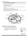
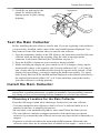
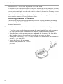
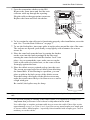
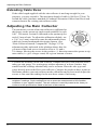
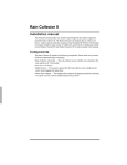
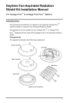
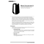
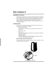
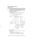
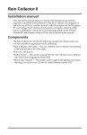
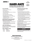
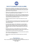
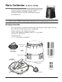
Rain Collector (# 7852 & 7852M)
This rain collector can be used with Vantage Pro2™
weather stations, including Vantage Pro2,
Vantage Pro2 Plus, and the Anemometer/Sensor
Transmitter Kit.
Note: Model number 7852 is factory-calibrated to take rain measurements in 0.01 inches. The
metric version, 7852M, comes factory-calibrated to take measurements in 0.2 mm.
Components
The rain collector includes the following components. Please make sure you
have all listed components before continuing.
• Rain collector cone latched onto base
• Base with tipping mechanism and 40’ (12 m) cable
• Four #8 x 3/4" screws
• Debris Screen
•16 3.5" bird spikes (optional).
14 Bird Spike
Sockets
Debris Screen
(fits snugly
inside cone)
RAIN
CONE
Finger Grips
Optional
Bird Spikes
TIPPING
MECHANISM
Latch
4 #8 X 3/4”
Screws
Base
40’ Cable
Prepare the Rain Collector
Tools and Materials Needed
You may need some of the following tools and materials to install the rain collector.
•Drill with 3/32” (2 mm) drill bit
•Medium Phillips screwdriver
•3/16” (or 5 mm) wrench
•Cable clips or weather-resistant cable ties with screw holes or other means for
mounting
•Small hammer (for optional bird spikes)
Rain Collector Internal Components
The illustration below shows the internal components of the rain collector, many of
which are referenced in this manual.
Tipping
Spoons
Magnet
Adjustment
Screw
Reed Switch
+
-
1
Adjustment
Guide
2
1
2
Drain
Screen
%
Restraining
Post
Cable Slot
Base
Latch
Opening
Prepare the Rain Collector
1. Turn the rain collector upside down and remove
the cone from the base by rotating the base until
the latches on the cone line up with the latch
openings in the base then lifting the base away
from the cone.
2
Bubble Level
Test the Rain Collector
2. Carefully cut and remove the
plastic tie which holds the
tipping spoons in place during
shipping.
Tipping Spoons
Plastic Tie
Test the Rain Collector
Before installing the rain collector, test the unit. If you are replacing a rain collector
you previously installed, make a note of the total rainfall amount displayed. You
may want to reenter this amount after you test the rain collector.
1. Open the transmitter shelter on the ISS. Remove the foam insert and feed the rain
collector cable up through the opening. Plug the cable to the appropriate
connector in the sensor interface (See illustration on page 5.)
2. Press the RAINDAY button on your console to display rainfall.
3. While watching the display on your console to see if it changes, slowly tip the
bucket until it drops to the opposite side. Each tip indicates 0.01" or 0.2 mm of
rain. (It may take up to a minute for the first tip to register at the console.) If the
display does not change, you may be tipping the bucket too quickly. Try again,
more slowly this time.If the rainfall amount displayed on the console increases by
the expected increment (either 0.01" or 0.2 mm) each time you tip the bucket,
your rain collector is working properly.
Install the Rain Collector
Note: Climbing on your roof may be hazardous. If you are uneasy about installing your unit
please have a qualified professional complete the installation. Davis specifically disclaims
any liability for injury or loss resulting from the installation or use of the rain collector.
Choosing a Location for the Rain Collector
Keep the following in mind when choosing a location for your rain collector:
•You must mount the rain collector so that it is level. A built-in bubble level is
attached to the base to simplify this process.
•Be sure there is an unobstructed path for water runoff from the drain screens.
•The rain collector contains a magnet-operated switch which may not operate
correctly if you mount the rain collector on or near any object which is attracted to a
magnet.
•Exposure to winds can reduce the measured rainfall amounts. Mount the rain
collector where there are no obstructions of rainfall at low angles -- such as trees,
3
Install the Rain Collector
houses, fences -- and as low as possible out of the wind.
To install the rain collector on a sheet metal roof, insulate the unit by making a platform
out of wood. Mount the base of the rain collector at least 1" (4 cm) away from any steel
or iron surface and make sure the reed switch is at least 1" (4 cm) away from any steel or
iron objects (e.g., nails).
•Choose a location which is easily accessible for normal cleaning and is distant from
trees or other sources of heavy pollen or debris.
Installing the Rain Collector
The following instructions assume the rain collector is being used with a Vantage
Pro2 or Vantage Pro2 Plus ISS. Refer to the user manual that came with your station
for more information.
Tip:
Manuals are available online at www.davisnet.com in the Weather Support section.
1. If you have not already done so, separate the cone from the base and disconnect
the rain collector cable from the sensor interface in the transmitter shelter.
2. Place the base on the mounting surface and mark the location of the four holes
(the base has eight to choose from) you will use to secure the base.
3. Make pilot holes using a 3/32" (2 mm) drill bit. You should make the pilot holes
about 1/2" (12 mm) deep.
4. Fasten the base to the mounting
surface using the #8 x 3/4” screws
provided.
4
Install the Rain Collector
5. Open the transmitter shelter on the ISS.
Remove the foam insert and feed the rain
collector cable up through the opening.
Plug the cable to the appropriate connector.
Replace the foam and close the shelter.
Transmitter
Shelter
Sensor
Interface
Foam
Insert
6. To be certain the rain collector is functioning properly after installation, retest the
unit. See “Test the Rain Collector” on page 3.
7. To use the bird spikes, insert one spike in each socket around the rim of the cone.
The sockets are tapered: push firmly or tap lightly with a hammer for a more
secure fit.
8. Place the cone back onto the base by putting the latches
on the cone into the latch openings in the base and
rotating the cone clockwise until the latches “lock” into
place. As you reattach the cone, make sure to run the
cable to the cable slot in the base, or the cone will not
fit snugly against the base.
9. Place the debris screen, pointed end up, into the cone.
The screen prevents large bits of debris from blocking
the funnel hole. If bird nesting is a problem, you can
place a spike in the hole on top of the debris screen.
Note that using a bird spike in the debris screen may
make the screen more likely to be blown over or out in
a high wind gust.
Be careful; bird spikes may be sharp.
Note: If you choose not to install bird spikes now, keep the packet of spikes for possible future
use.
10.To prevent fraying or cutting of the cable where it is exposed to weather, it is
important that you secure it so it doesn’t whip about in the wind.
Use cable clips or weather resistant cable ties to secure the cable. Place clips or ties
approximately every 3 to 5 feet (1 to 1.6 m). Do not use metal staples or a staple gun
to secure cables. Metal staples—especially when installed with a staple gun—have a
tendency to cut the cables.
5
Adjusting the Rain Collector
Extending Cable Runs
If the cable length supplied with the rain collector is not long enough for your
purposes, you may extend it. The maximum length of cable is 900 feet (274 m). To
extend the cable, purchase standard 4-Conductor Extension Cables from Davis and
connect them to the existing rain collector cable.
Adjusting the Rain Collector
The non-metric version of the rain collector is calibrated at
the factory so the spoons tip (and records rainfall) for each
0.01". The metric version is calibrated so the spoons tip for
each 0.2 mm of rain. To adjust the calibration slightly, use
a 3/16" (or 5 mm) wrench to rotate the adjustment screws
which are located underneath the tipping spoons. (See
“Rain Collector Internal Components” on page 2.) The
adjustment guide embossed in the platform shows how far
you must rotate both screws in turn to effect a 1% and a
2% change. Moving the screws in the positive (+) direction causes the spoons to tip
more times (i.e. give a larger count) for a given amount of water.
Note: Modify both adjustment screws by the same amount.
To check the accuracy of the rain collector, compare the Davis rain collector with a
tube type rain gauge. Use a rain gauge with an aperture of at least 4 inches. Any
smaller and the readings obtained may not be accurate. Place the tube type rain
gauge directly next to the Davis rain collector. Compare the totals on three storms to
determine whether your rain collector needs calibration and by how much.Adjust the
screws to fine-tune the reading for the next three storms if necessary.
Note: Avoid comparison to rainfall readings obtained from television, radio, newspapers, or
neighbors’ readings. Such readings are not an accurate measurement of the weather
conditions in your specific location. The rain collector is carefully tested at the factory to
conform to the specifications listed in the back of this manual.
6
Maintaining the Rain Collector
Maintaining the Rain Collector
For greatest accuracy, you should thoroughly clean the rain collector at least once or
twice a year.
1. Disconnect the rain collector cable from the sensor interface in the transmitter
shelter.
2. Separate the cone from the base.
3. Use a soft damp cloth to clean pollen, dirt, and other debris from the cone, cone
screens, and bucket.
4. Use a pipe cleaner to clear the funnel hole in the cone and the drain screens in the
base. When all parts are clean, rinse with clear water.
5. Reattach the cone and replace the debris screen.
6. Reconnect the rain collector cable to the sensor interface.
Troubleshooting Guide
Rainfall is not registering on the console or the console has a large error.
• Check the cable connections from the sensor to the console. Cable connections
account for a large portion of the potential problems.
Connections should be firmly seated in the jacks and plugged in straight. If you
think a connection may be faulty, try jiggling the cable while looking at the
display. If a reading appears intermittently on the display as you jiggle the cable,
the connection is faulty.
• Make sure there is no magnetic, steel, or iron object near the rain collector.
• Make sure the funnel hole in the cone is clear so water can empty into the bucket.
• Make sure the spoons move freely when tipping to both sides. The console should
show an increase in rainfall for each tip of the spoons. (If the spoons do not move
at all, check that you have cut the cable tie that holds them in place during
shipping.)
• Make sure the rain collector is mounted so that it is level.
•
Use the adjustment screws (See “Adjusting the Rain Collector” on page 6) to
adjust the rain collector’s sensitivity, if necessary.
7
Contacting Davis Technical Support
If you have any questions, or encounter problems installing or operating your rain
collector, please contact Davis Technical Support. We’ll be glad to help.
(510) 732-7814 — Monday - Friday, 7:00 a.m. - 5:30 p.m. Pacific Time.
(510) 670-0589 — Technical Support FAX.
[email protected] — E-mail to Technical Support.
[email protected] — General e-mail.
www.davisnet.com — Davis Instruments website. See the Weather Support section
for copies of user manuals, product specifications, application notes, and information
on software updates. Watch for FAQs and other updates.
Specifications
Sensor Type. . . . . . . . . . . . . . . . . . . . . .
Output . . . . . . . . . . . . . . . . . . . . . . . . . .
Attached Cable Length . . . . . . . . . . . . .
Cable Type. . . . . . . . . . . . . . . . . . . . . . .
Connector . . . . . . . . . . . . . . . . . . . . . . .
Recommended Max.Cable Length . . . .
Housing Material . . . . . . . . . . . . . . . . . .
Dimensions
Rain Collector and base. . . . . . . . . .
Tipping bucket with magnetic reed switch
Contact closure
40’ (12 m)
4-conductor, 26 AWG
Modular connector (RJ-11)
900’ (270 m)
UV-stabilized ABS plastic
8.75" diameter x 9.5" high
(22.2 cm diameter x 24 cm high)
Collection Area. . . . . . . . . . . . . . . . . 33.2 in2 (214 cm2)
Range
Daily Rainfall . . . . . . . . . . . . . . . . . . . 0.00” to 99.99” (0.0 mm to 999.8 mm)
Total Rainfall . . . . . . . . . . . . . . . . . . . 0.00” to 199.99” (0.0 mm to 6553 mm)
Accuracy . . . . . . . . . . . . . . . . . . . . . . . . For rain rates up to 2"/hr (50 mm/hr): ±4% of total
or +0.01” (0.2mm) (0.01" = one tip of the bucket),
whichever is greater. For rain rates from 2"/hr (50
mm/hr) to 4"/hr (100 mm/hr): ±5% of total or +0.01”
(0.2mm) (0.01" = one tip of the bucket), whichever
is greater.
Update Interval. . . . . . . . . . . . . . . . . . . . 20-24 seconds
Input/Output Connections
Red . . . . . . . . . . . . . . . . . . . . . . . . . . Switch terminal
Green & Yellow . . . . . . . . . . . . . . . . . Switch terminal
Product Number: 7852 Rain Collector
Part Number: 07395.334
Rev B (6/24/14)
This product complies with the essential protection requirements of the EC EMC Directive 2004/108/EC.
Copyright © 2014 Davis Instruments Corp. All rights reserved. Davis Instruments Quality Management
System is ISO 9001 certified. Information in this document is subject to change without notice.
®
3465 Diablo Avenue, Hayward, CA 94545-2778 U.S.A.
510-732-9229 • Fax: 510-732-9188
E-mail: [email protected] • www.davisnet.com