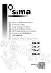
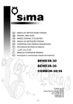
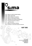
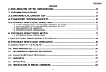
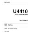
1
BEND3R-30
BEND3R-36
COMB3R-30/36
E-1
ENGLISH
“CE” DECLARATION OF CONFORMITY
SIMA, S.A.
Polígono Industrial Juncaril, C/ Albuñol, Parcela 250 C. P. 18220 Albolote, Granada (SPAIN)
Company responsible for manufacturing and commercialising the below specified machine:
BENDING
STEEL BARS BENDING AND CUTTING MACHINE
DECLARES:
That the already mentioned machine designed for bending and cutting flat and reinforced steel
bars for use in the structure and other construction components is in conformity with all
applicable provisions of the Directive of Machines (2006/42/CE) and the national applicable
regulations.
The machine is also in conformity with EC applicable provisions:
2006/95/CE; 2004/108/CE; 2000/14/CE; 2002/44/CE; 2002/95/CE; 2002/96/CE
The machine is also in conformity with the provisions of the following applicable norms
UNE-EN 292-1; UNE-EN 292 -2; UNE-EN 294; UNE-EN 349; UNE-EN 60204-1
UNE-EN 1050 ; UNE-EN 953
Details of the authorized person to elaborate the technical file
Eugenio Fernández Martín
Technical Department Manager
SIMA S.A.
Polígono Industrial Juncaril, C/ Albuñol, Parcela 250 - 18220 Albolote, Granada (SPAIN)
Albolote 01.01.2010
Signed:
Javier García Marina
Managing Director
-3-
ENGLISH
INDEX
“CE” DECLARATION OF CONFORMITY ............................................................ 3
1. GENERAL INFORMATION............................................................................ 5
2. GENERAL DESCRIPTION OF THE MACHINE................................................. 5
2.1 TRANSPORT .................................................................................................................. 6
2.2 PICTOGRAMS. ............................................................................................................... 6
3. ASSEMBLING INSTRUCCIONS .................................................................... 6
3.1 DELIVERY CONDITIONS .................................................................................................. 6
3.2 ACCESSORIES ASSEMBLING ............................................................................................ 7
4. MAIN PARTS OF THE MACHINE .................................................................. 7
4.1 CONTROL PANNEL .......................................................................................................... 7
4.2 PARTS OF THE PLATE...................................................................................................... 7
4.3 ANGLE INVERSION AND SELECTION PIVOT ........................................................................ 7
5. STARTING-UP AND USING THE MACHINE .................................................. 8
6. PLUGGING THE MACHINE TO THE ELECTRICITY ......................................... 8
7. BENDING WITH BOLTS AND MANDRILLS ................................................... 9
8. USE OF THE BENDING SQUARE .................................................................. 9
8.1 BENDING WITH BOLTS AND MANDRILLS ......................................................................... 10
9. SPECIAL ACCESSORIES ............................................................................ 10
10. MAINTENANCE, INSPECTION AND CONTROL.......................................... 10
10.1 CHANGING AND TIGHTENING THE BELTS ...................................................................... 11
10.2 BLADES SUBSTITUTION (COMB3R MODELS) .................................................................. 11
11. SOLUTIONS TO FREQUENT ANOMALIES ................................................. 12
12. TECNICAL CARACTERISTICS .................................................................. 13
12.1 BENDING CAPACITY.................................................................................................... 13
13. SAFETY RECOMMENDATIONS ................................................................ 13
14. ELECTRICAL SCHEMES............................................................................ 15
15. WARRANTY ............................................................................................ 18
16. ACCOUSTICAL NOISE DECLARATION...................................................... 18
17. DECLARATIONS ON MECHANIAL VIBRATIONS ....................................... 18
18. SPARE PARTS ......................................................................................... 18
19. ENVIRONMENT PROTECTION ................................................................. 18
WARRANTY CERTIFICATE ............................................................................ 22
-4-
ENGLISH
1. GENERAL INFORMATION
WARNING: Pease read and understand perfectly the present instruction before using the machine.
SIMA S.A. thanks you for your trust in our products and for purchasing the BENDING OR COMBINED
ELECTRICAL CUTTING/BENDING MACHINE.
This manual provides you with the necessary instructions to start, use, maintain and in your case, repair of
the present machine. All aspects as far as the safety and health of the users is concerned have been stated.
Respecting all instructions and recommendations guarantees safety and low maintenance. As such, reading this
manual carefully is compulsory for any person responsible for the use, maintenance or repair of this machine.
It is recommended to have always this manual in an easily accessible place where the machine is being
used.
2. GENERAL DESCRIPTION OF THE MACHINE
•
The BEND3R models have been manufactured to bend flat and reinforced steel bars used for construction and
passive steel armatures for structural concrete. The bending operation is done in cold using mandrills to
guarantee the bending interior diameter is conforming to the European norms.
•
The combined machines bending/cutting models COMB3R are designed to bend as well as cut steel bars. The
cutting tools are two blades, one fixed and one moving. The cutting operation is done manually by pushing
the bar on the roller, dropping the bar into the cutting throat, lowering the protection guard and pressing the
pedal.
Any other use of this machine is considered inadequate and can be dangerous. Thus, this is utterly
prohibited.
• The machine is equipped with an electrical auto-ventilated motor-brake
• The reducer is the main element of the machine. It is responsible for transmitting the needed energy to carry
out the steel bars bending.
• The machine is operated by an electrical motor that passes the movement, by a transmission to the bending
mechanism in which the different mandrills are mounted.
• The bending plate can be selected to work in two different senses, left or right, by changing the direction of
rotation in the electrical control panel.
• The bending angle can be decided by inserting the pivot in the bending plate. For a more precise bending, the
ruler can be accurately adjusted by its handle.
• The control panel is endowed with polyester, electrical knobs easily identified by pictograms.
• The machine is equipped with shutdown and backward movement buttons to facilitate its manoeuvre. The
emergency knobs on both sides of the machine can be used in case of danger or incorrect manoeuvres.
• The general bars bending manoeuvre is performed in low-voltage (24V) according to the European standards.
• The original equipment (bolts, mandrels bending square) are heat-treated to withstand the tough type of work
the machine performs.
• The machine is furnished with a pedal to confirm and execute the manoeuvre, thus avoiding the upper parts to
be trapped while the machine is running.
• The work area is protected by a safety guard to limit possible accidents. This guard is transparent to allow
observing the material being bended, avoiding getting to the upper parts of the bending area.
• The machine is equipped with wheels to facilitate their movement.
• The machine is painted in oven with a highly resistance, anti-corrosion epoxy polyester paint.
• The original, electrical equipment is in conformity with the EC safety norms.
• The COMB3R model is supplied with a cutting jaw with a safety metal guard connected to an electrical protection
system. When this safety guard is lifted, the machine stops working.
-5-
ENGLISH
2.1 TRANSPORT
For a safe transport of the machine, please follow the following instructions:
The Bending and Combined machines are fitted with wheels for easy displacement. They also have holes in the
working table to be lifted with cranes through chains or cables. The used means of transport must be safe. (Fig. A)
IMPORTANT: During the transport of the machine, the latter should never be reversed nor be put on either
side. The machine is only to rest on its four feet.
2.2 PICTOGRAMS.
Pictograms included in the machine entail the following:
USE HELMET AND EYE AND AUDITIVE
PROTECTION
READ INSTRUCTIONS
MANUAL
USE SAFETY GLOVES
3.
USE SAFETY BOOTS
ASSEMBLING INSTRUCCIONS
3.1 DELIVERY CONDITIONS
SIMA bending and cutting machines are delivered individually packed on a reinforced pallet. The following
items are sent together with the machine:
BEND3R 30
-
1
1
3
1
4
1
4
4
1
1
2
x
x
x
x
x
x
x
x
x
x
x
safety guard for the bending plate
pedal to operate the machine
mandrills ø60mm
mandrill ø100mm
bolts ø36mm.
bending squares
wheels
dispatchers R
Extender
Operator manual with warranty
wheels axis
-6-
ENGLISH
BEND3R 36 Y COMB3R 30/36
-
1
1
3
1
1
1
4
1
4
1
1
x
x
x
x
x
x
x
x
x
x
x
Safeguard for the bending plate.
pedal to operate the machine
mandrills ø60mm.
mandrill ø100mm.
mandrill ø140mm.
mandrill ø160mm.
bolts ø38mm.
bending square
wheels
Extenders
instruction manual and warranty
3.2 ACCESSORIES ASSEMBLING
For transport reasons, the plate safety guard (P, Fig.3) and the wheels kit (Fig.3.1) are disassembled.
Before using the machine, the plate safety guard should be mounted. The latter presses a security microswitch (M, Fig.3). In the counter case, the machine would not start.
4. MAIN PARTS OF THE MACHINE
4.1 CONTROL PANNEL
We will describe in (Fig. 4) the functionality of each of the knobs, switches, mechanisms and controls of the
machine.
1. Bending plate direction Selector: It selects the direction of the rotation of the bending plate.
2. Yellow Knob: It is used when we rose up the foot from the pedal or press any emergency stop, in case of
accidents or errors, and we want the bending plate back to its point of origin.
3. Green pilot: The ignited pilot indicates that the machine has got tension and has selected a sense of
rotation.
4. Emergency stop: It is used to stop the machine in case of emergency.
5. Angle adjustment wheel: It is used to regulate the accuracy of the angle that we cannot get with the
plate pivot. Its function is also to advance or retreat the bar mandrill support.
6. Pedal: It is used to confirm the bending plate rotation when it has been intentionally pressed. (Fig. 5)
7. Tension Entry: Electrical tension entry to the machine.
8. Red Pilot: It indicates the activation of the safety protection by overheating or short circuit in the motor or
control panel.
4.2 PARTS OF THE PLATE
The bending plate has 3 holes to insert the thrust bolt. Hole 1 is used with the spirals device. Hole 2 is used to
bend rods equal or smaller than 16mm diameter with the bolts and mandrels system. Hole 3 is used to bend rods
greater than 16mm diameter with the bolts and mandrels system. Threaded holes 4 serve as fans to extract and
dismantle the plate. (Fig.6)
NOTE: In rebar processing, the bar thrust must always be done with a mandrill put in the bolt. (Fig.7)
4.3 ANGLE INVERSION AND SELECTION PIVOT
The inversion pivot (Fig. B) It is used to select the plate rotation angle. Depending on the rotation direction
of the plate that we choose, we have to insert the pivot in different sectors.
-7-
ENGLISH
5. STARTING-UP AND USING THE MACHINE
ATENTION: All safety recommendations must be followed, either the ones mentioned in the present user
manual or those complying with all labour risks prevention norms in every location
WHEELWORK: SIMA bending and combined machines do not need any wheelwork operations as they are
specially designed to obtain the maximum performance from start.
NORMAL USE OF THE MACHINE:
The Bending and combined machines have been designed for bending and cutting flat and reinforced steel
bars for use in the structure and other construction components is in conformity with all applicable provisions of the
Directive of Machines (98/37/CE) and the national applicable regulations. Each other use that has not been
expressively indicated is considered abnormal. Any tool or accessory added or amended without written authorization
from the manufacturer is considered inappropriate and dangerous. If any damage or injury is caused as a result
thereof or by misuse of the machine, SIMA S.A. exempts all responsibility as manufacturer. The machine must be
installed on a plane, firm and horizontal surface and the ground should not be soft. This machine DOES NOT HAVE
TO BE USED UNDER THE RAIN. ALWAYS WORK IN WELL ILLUMIINATED AREAS.
6. PLUGGING THE MACHINE TO THE ELECTRICITY
The extension cable used to feed the machine needs to have a minimum section of 4x2.5 mm2 up to 25
meters long. For a superior distance 4x4 mm2 can be used. In one of its ends, it is needed to connect a base
normalised aerial of 3P+T or 3P+N+T compatible with the machine switch and in the other end, one normalised aerial
pin of 3P+T ó 3P+N+T compatible with switchboard exit.
Machines with electrical motor should always be connected to a normalised switchboard that
disposes of a magneto-thermal switch and a differential in accordance with the characteristics of the
motor:
2.2Kw /3 CV, three phase at 400V, 15A magneto-thermal and 15A/300mA differential.
2.2Kw /3 CV, three phase at 230V, 20A magneto-thermal and 20A/300mA differential.
3Kw / 4 CV, three phase at 400V, 15A magneto-thermal and 15A/300mA differential.
3Kw / 4 CV, three phase at 230V, 20A magneto-thermal and 20A/300mA differential.
The machine electrical tension is visible on the voltage indication next to the top of engine terminals and on
the machine characteristics plate.
WARNING: Do not plug the machine to the electricity if you are not sure of the available electrical tension. If
the tension is not correct, the engine will undergo irreparable harm or out of service.
WARNING: Never manipulate the power cables or any electrical equipment of the machine, if you have not
totally unplugged the machine from the electricity.
IMPORTANT: It is appropriate to change the position of the bridge plates in the engine terminals. It is also
important to change the adhesive labels indicating the voltage, to reflect the change made.
-8-
ENGLISH
7. BENDING WITH BOLTS AND MANDRILLS
To perform a 90º clockwise bending, we need to place the selector in the position of the wanted rotation.
Afterwards, we insert the pivot (P, Fig.8)) in the plate forming a fictitious 90º angle with the end of course F1,
responsible for reversing the plate rotation. Then, we press the pedal and watch the plate rotation, the pivot contact
with the micro and the plate goes back to its origin to make contact with the micro F2 which is responsible for stopping
the regression rotation.
NOTA: It is convenient to perform various angles before bending any bars so as to have a good
command of the machine.
To perform a 90º counter-clockwise bending, we need to place the selector in the position of the wanted
rotation. Afterwards, we insert the pivot (P, Fig.9) in the plate forming a fictitious 90º angle with the end of course
F1, responsible for reversing the plate rotation. Then, we press the pedal and watch the plate rotation, the pivot
contact with the micro and the plate goes back to its origin to make contact with the micro F2 which is responsible for
stopping the regression rotation.
NOTA: It is convenient to perform various angles before bending any bars so as to have a good
command of the machine.
NOTA: Depending on the diameter of the bar to be bended and its hardness, we have to find the adequate
sector to place the inversion pivot. If you do not get the desired angle with the inversion pivot, you will have to refine
the accuracy of the angle with the ruler adjusting wheel (P, Lot). As such, you regulate the bar support angle
influencing the angle to make.
8. USE OF THE BENDING SQUARE
The bending square is used to bend bars with diameter equal to or lower than 16mm. To make a sample,
proceed as follows, bending by the extreme right of the operator.
1. Plug the machine to the electricity.
2. Place the bending blade rotation direction selector in the adequate position (Clockwise).
IMPORTANTE: Check the angle and the rotation direction with the inversion pivot before mounting
any accessories on the table to avoid accidents.
3. Mount the bending square in the right ruler of the machine on a bolt. (E, Fig.10)
4. Place a second bolt to serve as a support of the bending square. (B2, Fig.10)
5. Insert the thrust bolt and the cap in the hole of the bending plate #1 (B3 Fig.10).
6. Insert another bolt in the centre of the plate and a chuck to obtain the desired ratio. (B4, Fig.10).
7. Introduce the bar and press the pedal to obtain the selected angle.
-9-
ENGLISH
8.1 BENDING WITH BOLTS AND MANDRILLS
To bend bar with diameter greater than ø16mm, use the bolts and mandrills system in stead of the bending
square. To make a sample proceed as follows:
1. Plug the machine to the electricity.
2. Place the selector in the adequate rotation position (clockwise) to make the bar entry on the right side of
the machine. Check the angle with the inversion pivot before mounting any accessories on the table.
3. Place in the centre of the plate the central bolt and the appropriate mandrill for the ratio we want to obtain.
(B1, Lot)
4. Place the thrust bolt and mandrill (B2, Lot)
5. Place the support bolt over the chuck to support the bar so as to be as linear as possible (B3, Lot)
6. Introduce the bar, press the pedal and get the result. If the angle obtained is not the desired one, we will
have to change the place of the inversion pivot or spin the wheel (P, Lot) moving the ruler forward to get finer angle.
9. SPECIAL ACCESSORIES
The bending machines come with optional accessories, designed for the implementation of various functions
such as:
1. STERRUPS DEVICE: This device has been designed to make stirrups with an inferior ratio thanks to its
special bolt (B, Fig.12), A ruler has also been incorporated (R, Fig.12) with two caps (T1 y T2, Fig.12) to
make stirrups on measurement.
2. SPIRALS DEVICE: This device has been designed to make stirrups in spiral forms. We can introduce bars
from 6 to 20mm easy to adjust (A, Fig.13). The spiral diameter is also adjustable (B, Fig.13) with a maximum
diameter capacity of 5 m. The spiral pass is another point that can be adjusted (C, Fig.13).
3. BIG RATIOS DEVICE: This device has been designed to bend bars with a ratio in conformity with the
European bending norms. It is compound of a number of accessories and mandrills a minimal ratio specific for each
bar diameter. (Fig.14)
4. ENTRANCE ROLLERS KIT: This kit has been designed to make it easy to slip the bars and protect the
working tale from premature wear-out that can be caused by rubbing the bar.
10. MAINTENANCE, INSPECTION AND CONTROL
1 First oil change at 500 hours of use if it is mineral, subsequently at the end of 2000/5000 hours of work or
three years regardless of the hours of operation of the machine; or at the end of 20,000 hours in case of synthetic oil.
2 Lubricate weekly with calcium grease the holes where the bolts are housed and the bottom of the bolt to
avoid corrosion.
3 At the end of each day, unplug the machine.
4 If the machine is not covered, wrap it with an impermeable cloth.
5 When necessary, remove the remains of material that have fallen inside the machine.
6 Regularly clean the visible parts and grease the holes in the table, bending plate and bolts.
ATENCION: before performing any maintenance or cleaning operations, the electricity cable should be
unplugged.
- 10 -
ENGLISH
TABLE OF EQUIVALENCE OF OILS AS PER MANUFACTURER
MANUFACTURER
TYPE OF OIL
CEPSA
ENGRANAJ. HP-460
REPSOL
SUPER TAURO-460
ESSO
SPARTAN EP-460
MOBIL
MOBIL GEAR-634
SHELL
OMALA-460
B.P.
ENERGOL GR-XP
10.1 CHANGING AND TIGHTENING THE BELTS
The machines leave the factory with the belts perfectly tightened. It is posible that alter the
installation of the machine and alter using for a long time, the belts get loose. To tighten back the belt or replace it,
please consider the following steps (Fig.16)
1. Make sure the machine is unplugged from the power supply.
2. Remove the back and front doors of the frame of the machine.
3. Loosen with a key the four screws (A, Fig.16), lo Just enough for the motor to be displaced.
4. Depending on what we want to do, tighten or change the belt, we have to deal with the tightening screws. (B,
Fig.16) in a sense or the other. When tightening, make sure all belts have the same tension.
5. Once the belts have been tensed, you can fasten back the screws (A, Fig.16).
10.2 BLADES SUBSTITUTION (COMB3R MODELS)
If any of the cutting blades is damaged, replace them as to the following procedure: (Fig.17)
1
2
CHANGING THE FIXED BLADE. Make sure the machine is unplugged from electricity. Lift the safety
guard off the blades. Afterwards, remove the screws and rotate the blade for a new cutting session or
substitute it with a new blade if necessary.
CHANGING THE MOVEABLE BLADE. To change this blade, it is necessary that the connecting rod is
displaces outside its housing. Operate in the following way: with the machine switched on and the
inversion pivot of the bending plate removed from its position, press the pedal and observe the
movement of the blade. When we see that the blade is outside its housing, we depress the pedal. Right
after, we unplug the machine from the electricity to avoid any accident. In this way, we can reach the
screws that fix the blade. Remove the screws of the blade for a new cutting or substitute it with a new
blade if necessary.
- 11 -
ENGLISH
11. SOLUTIONS TO FREQUENT ANOMALIES
ANONMALY
Cutting/bending power insufficient
The bending plate turns but only stops after
touching the course end.
POSSIBLE CAUSE
SOLUTION
Loose or damaged belts
Tighten or substitute belts.
Damaged blades
Change the cutting face or substitute it.
Power drop in motor.
Let the motor be revised by technical service.
Check the stopping course end and confirm its
Defect end of course
continuity. (1 open, 0 closed). Substitute it in case
of defect.
Faulty tension in the energy supply board
Defect electrical connection
Revise electrical switchboard of the workplace
Check there is tension in the workplace
Check the network power tension of the workplace
and its connections.
Faulty tension the machine, the pilot lamp
indicating the state of energy does not ignite.
Disconnection of the manoeuvre circuit breaker
Reactivate the circuit breaker
The conducting electrical cable is in a bad state.
Check the state and connection of the cables.
Check all phases of the machine are connected.
The machine is not well connected.
Control the high tension fuses of the machine
electrical switchboard.
The pilot lamp indicating the state of energy but
the machine does not function.
Emergency …. blocked
Unblock emergency ….
Make sure all safety devices of doors, guards,
Safety electrical elements deactivated
Over-heating of the engine
Pilot lamp red-ignited
Circuits cut in the engine fazes
During the recession after the bending,
on the circuit breaker
Check installation
less than 230V, the machine does not work. A
Tension unstable
tension stabilizer is then recommended.
Deteriorated or damaged locks
Check the locks and substitute them in case they
Oil leaking from the lower part of the reducer
the plate does not stop at the starting point.
Wait until the engine has cooled down and switch
Check out of the emission stream. If the voltage is
Connection to 230V. The connection is
regular but the machine does not have enough
strength.
emergency … are operational
are defect.
Check the end of course and its continuity (1 open
Defect course end
0 closed). Substitute it in case of defect.
Check the electro-break and adjust it tightening
Electro-break misadjusted by wearing-out
the springs and leaving an evenly Light of 0,300,40 mm between disk and block, using graduate
The bending plate does not instantly stop at the
gauges for this adjustment.
end of each manoeuvre
Disk of the electro-break worn-out
Substitute the disk block.
Interior deterioration of some elements
Dismount the reducer block and verify the
Strange noises in the reducer block
Strange noise in the motor
bearings and gears, substitute all that is defect.
Some motor components breakdown
- 12 -
Control where the noise comes from, discount the
motor and proceed with its repair.
ENGLISH
12. TECNICAL CARACTERISTICS
DETAILS
MOTOR POWER
BEND3R-30
BEND3R-36
COMB3R-30/36
2,2Kw
3Kw
3Kw
230v~ / 400v~
50Hz ó 60Hz.
230v~ / 400v~
50Hz ó 60Hz.
230v~ / 400v~
50Hz ó 60Hz.
1500r.p.m.
1500r.p.m.
1500r.p.m.
NET WEIGHT
292 Kg.
348 Kg.
427 Kg.
DIMENSIONS
LxAxH (mm.)
998x880X1078
927x841x1071
927x1056x1071
PLATE R.P.M.
12
10
10
4,2 L.
8 L.
8 L.
TENTION MOTOR
MOTOR R.P.M.
REDUCER CAPACITY
12.1 BENDING CAPACITY
ELASTIC LIMIT
RESIS.TRACTION
Nºx
BEND3R-30
BEND3R-36
BEND3R-45
BEND3R-52
R=N/mm² 250
R=N/mm² 450
1
2
3
Ø30 Ø24 Ø18
Ø36 Ø26 Ø22
Ø45 Ø32 Ø25
Ø52 Ø36 Ø30
R=N/mm² 480
R=N/mm² 650
1
2
3
Ø25 Ø20 Ø16
Ø32 Ø24 Ø18
Ø40 Ø32 Ø25
Ø46 Ø34 Ø26
R=N/mm² 650
R=N/mm² 850
1
2
3
Ø25 Ø18 Ø14
Ø32 Ø22 Ø16
Ø40 Ø26 Ø25
Ø42 Ø32 Ø25
13. SAFETY RECOMMENDATIONS
Bending and combined (bending/cutting) machines, be used by trained people or people familiarized with
their operation.
•
Before starting up the machine please read the instructions and make sure safety norms are
respected. Learn how to stop the machine in a fast and safe way.
•
Place the machine on a plane surface. Connect the machine to the electricity only when you are sure
of its stability.
•
Start the machine only when you have mounted the safety guards that come with the machine.
•
It is recommended to use safety glasses, safety boots, gloves etc. Please always use approved
materials.
•
Always use Individual Protection Equipment (IPE) in accordance with the type of work you are
effectuating.
•
Prohibit strangers to access the place of work of the machine.
•
Work clothes are not supposed to have loose articles that can cling into movable parts of the
machine.
- 13 -
ENGLISH
•
When you have to move the machine, unplug the electricity cables and block the moving parts of the
machine.
•
Always keep protection elements and the safety guards in their correct positions.
•
Attention: Before placing the bolts, mandrills and the bending squares, check the direction of
rotation of the bending plate. You can then install the suitable accessories for the type of work you
want to make.
•
The damaged electrical cables should be urgently replaced.
•
Unplug the machine from the electricity and never manipulate nor operate on the mechanical nor
electrical elements of the machine while the engine is on.
•
Never use the machine for purposes other that those it has been designed for.
VERY IMPORTANT: Always use earth plug before starting-up the machine.
• Use normalised cables
• Make sure the feeding voltage is in accordance with the voltage indicated in the adhesive label on the machine.
• Make sure that the extension cords are not in contact with points of high temperature, oil, water, sharp edges.
Also avoid trampling or crushing the cables by passing vehicles and do not put any objects on the machine.
• Do not use high pressure water to clean circuits or electrical elements.
ATTENTION: You are to follow all safety recommendations mentioned in the present user manual and
comply with all labour risks prevention norms in every location.
SIMA, S.A. is not responsible for the consequences possibly generated but the inadequate use of the
bending or the combined (bending/cutting) machine.
- 14 -
ENGLISH
14. ELECTRICAL SCHEMES
- 15 -
ENGLISH
- 16 -
ENGLISH
- 17 -
ENGLISH
15. WARRANTY
SIMA, S.A. the manufacturer of light machinery for construction possesses a net of technical services “SERVISIMA”.
Repairs under warranty made by SERVÍ-SIMA are subject to some strict condition to guaranty a high quality
and service.
SIMA S. A. guarantees all its products against any manufacturing defect; to take into account the conditions stated in
the attached document “WARRANTY CONDITIONS”. The latter would cease in case of failure to comply with the
established payment terms. SIMA S.A. reserves its right to bring modifications and changes to its products without
prior notice.
16. ACCOUSTICAL NOISE DECLARATION
These are the acoustic levels emitted by the MACHINE is inferior to 70 dB (A)
17. DECLARATIONS ON MECHANIAL VIBRATIONS
The machine does not generate any mechanical vibrations that present health and workers safety risks.
18. SPARE PARTS
The spare parts for the bending and combined machines, manufactured by SIMA, S.A. are to be found in the
spare parts plan, attached to this manual.
To order any spare part, please contact our alter-sales service clearly indicating the serial number of the
machine, model, manufacturing number and year of manufacturing that show on the characteristics plate.
19. ENVIRONMENT PROTECTION
Raw materials have to be collected instead of throwing away residuals. Instruments, accessories, fluids and packages
have to be sent into specific places for ecological reutilisation. Plastic components are marked for selective recycling.
R.A.E.E. Residuals arising of electrical and electronic instruments have to be stored into specific places for
selective collection.
- 18 -
ENGLISH
A
B
3
3.1
4
5
6
7
- 19 -
ENGLISH
8
9
10
11
12
13
- 20 -
ENGLISH
14
15
17
16
16
5
- 21 -
ENGLISH
WARRANTY CERTIFICATE
AFTER-SALES SERVICE
END USER FORM
MACHINE DETAILS
NUMBER PLATE
CLIENT DETAILS
NAME
ADDRESS
POSTAL CODE AND CITY
PROVINCE/COUNTRY
TEL.:
Fax:
E-mail
DATE OF PURCHASE
Signature and stamp of the selling party
Client signature
WARRANTY CONDITIONS
1.) SIMA, S.A. fully guarantees all its products against defects in design, taking responsibility in the repairs or the faulty equipment for a period of ONE year
from the original date of purchase. The date of purchase must appear on the warranty voucher enclosed.
2.) The warranty covers exclusively labour, repair and substitution of the faulty parts, the model and serial number of which must show on the warranty
certificate.
3.) Transport, stay and food expenses before arriving to SIMA S.A., will be covered by the client.
4.) The warranty does not cover any damage caused by the normal wear, undue usage, overloading, inadequate installation or bad conservation of the
machine.
5.) All repairs under WARRANTY will solely be effectuated by SIMA, S.A. or by its authorised dealers or repair centres.
6.) This Guarantee will be invalid in the following cases:
a) Any Warranty certificate manipulation or modification
b) Repairs, modifications or substitution of any part of the machine by unauthorized parties by SIMA S.A technical department.
c) The non-approved installation of devices by SIMA S.A technical department.
7.) SIMA is not responsible for any damages caused by the failure of the product. This includes, but not limited to, annoyances, transport expenses, telephone
calls and loss of personal goods or commercial benefits, as well as the loss of pay or salary.
8.) Faulty thermal or electrical motors under warranty have to be sent to SIMA S.A or its authorized technical service in the country.
9.) To be benefit from the warranty, the warranty certificate must be at SIMA S.A premises within 30 days from the purchasing date. To claim the warranty,
the purchase invoice has to be attached stamped by the dealer including the serial number of the machine.
SOCIEDAD INDUSTRIAL DE MAQUINARIA ANDALUZA, S.A.
POL. IND. JUNCARIL, C/ALBUÑOL, PARC. 250
18220 ALBOLOTE (GRANADA)
Tel.: 34 - 958-49 04 10 – Fax: 34 - 958-46 66 45
MANUFFACTRURER OF LIGHT MACHINERY FOR CONSTRUCTION
SPAIN
- 22 -
ENGLISH
WARRANTY CERTIFICATE
AFTER-SALES SERVICE
FORM TO RETURN TO MANUFACTRURER
DATOS MÁQUINA
NUMBER PLATE
DATOS COMPRADOR
NAME
ADDRESS
POSTAL CODE AND CITY
PROVINCE/COUNTRY
TEL.:
Fax:
E-mail:
DATE OF PURCHASE
Signature and stamp of the selling party
Client signature
WARRANTY CONDITIONS
1.) SIMA, S.A. fully guarantees all its products against defects in design, taking responsibility in the repairs or the faulty equipment for a period of ONE year
from the original date of purchase. The date of purchase must appear on the warranty voucher enclosed.
2.) The warranty covers exclusively labour, repair and substitution of the faulty parts, the model and serial number of which must show on the warranty
certificate.
3.) Transport, stay and food expenses before arriving to SIMA S.A., will be covered by the client.
4.) The warranty does not cover any damage caused by the normal wear, undue usage, overloading, inadequate installation or bad conservation of the
machine.
5.) All repairs under WARRANTY will solely be effectuated by SIMA, S.A. or by its authorised dealers or repair centres.
6.) This Guarantee will be invalid in the following cases:
a) Any Warranty certificate manipulation or modification
b) Repairs, modifications or substitution of any part of the machine by unauthorized parties by SIMA S.A technical department.
c) The non-approved installation of devices by SIMA S.A technical department.
7.) SIMA is not responsible for any damages caused by the failure of the product. This includes, but not limited to, annoyances, transport expenses, telephone
calls and loss of personal goods or commercial benefits, as well as the loss of pay or salary.
8.) Faulty thermal or electrical motors under warranty have to be sent to SIMA S.A or its authorized technical service in the country.
9.) To be benefit from the warranty, the warranty certificate must be at SIMA S.A premises within 30 days from the purchasing date. To claim the warranty,
the purchase invoice has to be attached stamped by the dealer including the serial number of the machine.
SOCIEDAD INDUSTRIAL DE MAQUINARIA ANDALUZA, S.A.
POL. IND. JUNCARIL, C/ALBUÑOL, PARC. 250
18220 ALBOLOTE (GRANADA)
TEL: 34 - 958-49 04 10 – Fax: 34 - 958-46 66 45
MANUFFACTRURER OF LIGHT MACHINERY FOR CONSTRUCTION
SPAIN
- 23 -
ENGLISH
- 24 -