1
AK600™
Pool and Spa Controller
Installation and
Operation guide
800-831-7133
www.pentaircommercial.com
www.pentairpool.com
TABLE OF CONTENTS
ChApTEr 1 INFOrMATION
1.1
1.2
1.3
1.4
1.5
SAFETY PRECAUTIONS................................................................................
WARRANTY
................................................................................
AK600PS OVERVIEW ................................................................................
INTROdUCTION
................................................................................
ImPORTANCE OF WATER mAINTENANCE ........................................................
4
5
6
7
9
ChApTEr 2 INSTALLATION
2.1
2.2
2.3
2.4
2.5
2.6
2.7
2.8
2.9
2.10
2.11
INSTAllATION PREPARATION ......................................................................
mOUNTINg ThE AK600 ...............................................................................
PlUmbINg INSTAllATION ...........................................................................
ElECTRICAl SPECIFICATIONS .....................................................................
INPUT VOlTAgE SElECTION ........................................................................
AK600 INSTAllATION CONFIgURATION ........................................................
ChEmICAl FEEd PUmP INSTAllATION ..........................................................
SOlENOId lOCATION ................................................................................
SANITIzER lOCATION
FlOW OR PRESSURE SWITCh ......................................................................
USINg AN ExISTINg mAIN TImER ................................................................
10
14
15
16
17
18
20
`
ChApTEr 3 hArdwArE
3.1
3.1.1
3.1.2
3.1.3
3.1.4
mOdUlES
................................................................................
SENSOR mOdUlES
................................................................................
COmmUNICATION mOdUlES ........................................................................
RElAY mOdUlES
................................................................................
REmOT RS485 mOdUlES.............................................................................
16
16
16
16
ChApTEr 4 AK1200 FLOw CELL
4.1
4.1.1
4.1.2
4.1.3
4.1.4
AK1200 FlOW CEll ................................................................................
FlOW CEll ASSEmblY ................................................................................
FlOW CEll mOUNTINg ...............................................................................
INlET ANd ExIT lINES ...............................................................................
SENSORS
................................................................................
18
18
19
19
19
ChApTEr 5 SENSOrS
5.1
5.2
5.3
5.4
5.5
5.6
5.7
5.8
Ph ANd ORP SENSORS ...............................................................................
CAlCUlATEd PPm
................................................................................
AKCOlOR PPm
................................................................................
TEmPERATURE SENSOR ..............................................................................
FlOW SENSORS
................................................................................
PRESSURE SENSOR
SENSOR CARE
................................................................................
FINIShINg ANd TESTINg ThE INSTAllATION ................................................
20
21
21
21
21
22
22
ChApTEr 6 OpErATIONS
6.1
6.1.1
6.1.2
6.1.3.
AK600PS WINdOW NAVIgATION .................................................................. 23
SElECTINg ITEmS
................................................................................ 24
ChANgINg ITEm VAlUES ............................................................................ 24
AlPhANUmERIC KEYbOARd .........................................................................
ChApTEr 6
6.2
6.3
6.4
6.4.1
6.4.2
6.4.3
6.4.4
6.4.5
6.4.6
6.4.7
6.5
6.5.0
6.5.1
6.5.2
6.5.3
6.5.4
6.6
6.6.1
6.6.2
6.6.3
6.6.4
6.6.5
6.6.6
6.6.7
6.6.8
6.6.9
6.6.10
6.6.11
6.6.12
6.6.13
6.6.14
(CONTINuEd)
START UP
................................................................................
INITIAlIzINg ThE AK600PS25
dISPlAY SCREEN
................................................................................
CAlIbRATINg TEmPERATURE26
CAlIbRATINg Ph
................................................................................
CAlIbRATINg ORP
................................................................................
CAlIbRATINg CAlCUlATEd PPm ..................................................................
mANUAl RElAY CONTROl ...........................................................................
RElAY TImER dISPlAY ................................................................................
SET UP FlOW
................................................................................
mAIN mENU
................................................................................
NAmE
................................................................................
SYSTEm
................................................................................
dATA
................................................................................
SECURITY SETUP
................................................................................
SERVICE
................................................................................
PROgRAmmINg
................................................................................
WIzARdS
................................................................................
CONTROl TYPE
................................................................................
PRObE ClEAN
................................................................................
hEATER
................................................................................
AlARm OUT
................................................................................
Ph, mIxINg TImE CONTROl ........................................................................
Ph CYClE TImE CONTROl ...........................................................................
AUx: mAKE UP
................................................................................
dAIlY
................................................................................
WEEKlY
................................................................................
PPm mIxINg TImE CONTROl .......................................................................
PPm CYClE TImE CONTROl .........................................................................
ORP CYClE TImE CONTROl .........................................................................
ORP mIxINg TImE CONTROl .......................................................................
ChApTEr 7 TrOuBLEShOOTING
7.1
7.2
7.3
7.4
7.5
7.6
TROUblEShOOTINg ................................................................................
ThE REAl TImE ClOCK ...............................................................................
ORP TROUblEShOOTINg ...........................................................................
USINg ThE TEST STRIP ..............................................................................
AK COlOR PPm TROUblEShOOTINg .............................................................
Ph TROUblEShOOTINg ..............................................................................
ChApTEr 8 AppENdIXES
8.1
8.2
8.3
8.4
UTIlITY PASSWORdS ................................................................................
SET UP dIgITAl FlOW ................................................................................
PROPORTIONAl FEEd ................................................................................
QUICK KEYS
................................................................................
ChApTEr 9 dIAGrAMS
9.1.1
9.1.2
9.1.4
9.1.1
9.1.3
ExPlOdEd VIEW
PARTS lIST
WIRINg
SENSOR WIRINg
mENU TREE
................................................................................
................................................................................
................................................................................
................................................................................
................................................................................
25
26
27
27
28
28
29
29
30
31
32
32
32
32
33
36
36
37
37
37
37
38
39
39
39
40
40
41
42
42
42
43
43
44
44
45
45
46
47
48
49
50
51
52
AK600
ChApTEr 1
INFOrMATION
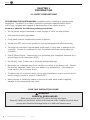
1.1 SAFETY prECAuTIONS
pLEASE rEAd ThIS uSEr MANuAL completely before installing or operating the
equipment. The AK600 is a Class 1 product for protection against electric shock
and a Type 1 product with regards to disconnection of the control circuits.
Be sure to observe the following safety precautions:
•
Do not permit anyone untrained or under the age of 18 to use this product.
•
Unit must be properly grounded.
•
Front panel must be closed before power is applied.
•
Always turn OFF main circuit breaker to unit and all equipment before servicing.
•
Touching the controller’s internal parts could result in injury and or damage to the
controller. In case of a malfunction, only a qualified technician should repair the
controller.
•
Risk of Electric Shock. Connect only to a grounding type receptacle protected by a
ground-fault circuit interrupter (gFCI).
•
Do not bury cord. Route cord to eliminate external damage.
•
Be careful not to damage any of the insulation on wires or the power cord. Should
the cord be damaged, return it to your dealer for a replacement. Continued use
could result in fire or electric shock.
•
To reduce the risk of electric shock, do not use an extension cord to connect unit to
electric supply, provide a properly located GFCI.
•
Never remove or install any cables on the circuit cards when power is applied,
damage to the components may occur.
SAVE ThIS INSTruCTION GuIdE!
wArNING:
ChEMICAL BurN hAZArd
make sure pumps are OFF before drilling into pipes.
Securely fasten all electrical, water and chemical lines. locate chemical feed
pumps and chemical storage tanks in a safe and secure area.
!
4
Pentair Water Commercial Pool and Aquatics™
12-15-07
AK600
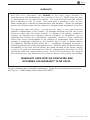
wArrANTY
A c u - Tr o l I n c . w a r r a n t s t h e A K 6 0 0 t o b e f r e e f r o m d e f e c t s i n
manufacturing and workmanship for a period of five (5) YEARS from the date
of manufacture for the electronic module. All commercial ph and ORP sensors
have a warranty of two (2) years. Flow cells have a warranty of one (1) year.
Other equipment is covered by manufacturer’s own warranty. During the warranty
period, any defective parts will be repaired or replaced when necessary by Acu-Trol.
This warranty does not cover: (a) the buyers’ labor or any servicing fees
related to replacement of the Product; (b) damage resulting from the use of this
Product in other than its normal manner; (c) damage from misuse, accident or
neglect; (d) damage from improper testing, operation, or installation; (e) not
operating the Product on a dedicated (separate) circuit or under conditions
other than those recommended or at voltages or amperages other than the
voltage or amperage indicated on the Product; and (f) acts of Mother Nature
(i.e. lightning, electrical storms, floods, etc.).
In addition, attempting to service or
modify the product will render this warranty void. Defective parts should be returned
immediately to the local Acu-Trol dealer, any parts returned to the factory require
a return of material authorization code to subsequently generate an RmA
(Returned materials Authorization form). An Acu-Trol technician will analyze
the returned part and determine the cause of failure and process accordingly.
wArrANTY CArd MuST BE COMpLETEd ANd
rETurNEd FOr wArrANTY TO BE VALId.
The blue warranty card is included in packaging. Please fill out information and return to
Acu-Trol, Inc., 11830 Kemper Road, Auburn CA, 95603.
12-15-07
Pentair Water Commercial Pool and Aquatics™
5
AK600
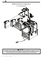
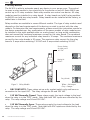
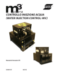
AK600 Installation Configuration
2.7.1 Exploded View
!
WARNING
For 230 VAC Power the AK600 Input Voltage Selection Switch MUST be changed from 115 VAC
to 230 VAC or damage will occur to the AK600. This damage is NOT covered by the warranty.
Do NOT connect any load not rated for the supply voltage to any of these relays.
6
Pentair Water Commercial Pool and Aquatics™
12-15-07
AK600
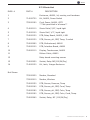
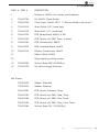
2.7.2 parts List
dWg. #
PART #
1
dESCRIPTION
Enclosure, AK600, lid, overlay, and hardware
2
714000720
Kit, AK600, Power Switch
3
755000190
Cord, Power, AK600, gFCI
** Not permitted in all areas**
4
714000110
Strain Relief, 5/8”, liquid tight
5
714000100
Strain Relif, 1/2”, liquid tight
6
724000120
PCb, Relay board, AK600, 4 NO
7
724000130
PCb, Sensor, ph, ORP, Temp, 3 switch
8
724000090
PCb, motherboard, AK600
9
724000100
PCb, Interface board, AK600
10
724000110
display, Touchscreen, AK600
11
Ribbon Cable, AK600
12
Relay board mounting screws
13
724000050
Socket, Relay NO(110/24/dry)
14
714000120
Kit, latch, Integra Enclosure
725000020
modem, Standard
735000010
modem, Wireless
724000150
PCb, Sensor, Pressure, Temp
724000160
PCb, Sensor, ph, ORP, Cond, Temp
724000180
PCb, Sensor, ph, ORP, Color, Temp
724000190
PCb, Sensor, ph, ORP, Color, Cond, Temp.
724000060
Socket, Relay, NC (110/24/dry)
Not Shown
12-15-07
Pentair Water Commercial Pool and Aquatics™
7
AK600
1.3
AK600 OVErVIEw
Acu-Trol, a technological leader in swimming pool automation, congratulates you on
your selection of the AK600 swimming pool controller. The AK600 will maintain the ph
and sanitizer levels, maintain a set temperature, and control up to 16 external devices in a pump room, on up to three pools or spas. The AK600 is specifically designed
to be easy to use and install while meeting the needs of the most demanding applications.
The AK600 features:
MOduLAr dESIGN: The AK600 is designed to grow with your needs.
Increase the number of bodies of water, add true PPM control, conductivity control, or
add additional relays to automate your pump room. The AK600 can be easily modified at the installation site with only a few basic tools.
INTErFACE: The AK600 uses a touch screen display panel with a built in graphical user interface for simple operation. A full alphanumeric keyboard is
available for easy calibration and programming. An automatic backlight ensures clear
visibility of the touch panel, and conserves power by turning on only when the touch
screen is in use.
MEMOrY: The AK600 has built-in memory that automatically saves your
programming. If your controller ever loses power, it will retain all programmed
values.
dATA rECOrdING: The AK600 has the ability to record data from all sensors
and to store up to 6505 measurement lines, the equivalent of 271 days of hourly recordings.
CALCuLATEd rEAdINGS: The AK600 calculates and displays the free
available chlorine, scaling index values for each body of water, and two (2) differential readings based on the four (4) pressure sensors.
rELAYS: The ability to control up to 16 relay modules enables the AK600 to
automate nearly every device in your pump room. There are various types of relay
module configurations available to meet most load requirements.
dETAILEd dISpLAY: In addition to the chemical readings, the AK600 will display important information about the relays controlling each device. It will tell your
operator whether each relay is currently on or off, how long each relay has been on,
and any relays that have reached their programmed time limits and are now in alarm.
SENSOrS: The AK600 can interpret readings from many types of sensors,
allowing you to measure pH, ORP, true PPM, Temperature, pressure, and conductivity.
Each sensor has it's own unique circuitry, isolating it for more exact measurements.
VOLTAGE: The AK600 can be configured to use either 115 VAC or 230 VAC. This
allows the controller to be plugged in to an existing outlet, or wired directly in to the
electrical system.
8
Pentair Water Commercial Pool and Aquatics™
12-15-07
AK600
The AK600 Installation, Operation and Programming Guide explains the procedures
for proper installation and operation. Section one (1) the installation guide, consists
of chapters 2, 3, 4, and 5, and introduces the parts of the controller and the process
to follow when installing the electrical and plumbing portions.
Section two (2) the operation guide, consists of chapter 6, and describes all the available screens and menus of the controller, from navigating and initializing the screens
to programming and customizing specifications. Section three (3) the programming
guide, consists of chapters 7, 8, 9, 10, 11, and 12, and describes troubleshooting
strategies, optional devices that may be added to your AK600, and many of the relevant charts and diagrams..
1.5 The Importance of water Maintenance
A chemical controller is designed to maintain specific levels of disinfecting and
balancing chemicals. disinfecting chemicals help to control the growth of bacteria and
other organisms in the water of a pool or spa. balancing chemicals keeps a pool or
spa at a certain pH level, preventing the water from becoming acidic, and corroding
the pool and its equipment, or becoming basic, and causing buildup on the equipment.
Water maintenance is an important part of operating a pool and spa. Pool operators should be trained in water maintenance by an authority recommended by their
local health department. Water maintenance requirements are generally determined
by the county or state and can vary widely. However, most requirements fall within
the following range recommended by the National Swimming Pool Foundation:
Filtration: Minimum turnover rate of six hours for a pool and
30 minutes for a spa.
water Balance: – ph 7.2 – 7.6, alkalinity 80-120 PPm.
Oxidation reduction potential (ORP) – A reading of 650 mV - 750 mV.
Total dissolved Solids - Should not exceed 2000 PPM.
(excluding pools using a salt chlorine generator)
This information is meant to provide pool operators with a basic idea of the
range of water maintenance requirements, and the importance of water maintenance.
To ensure that your facility is in compliance with all local regulations please check
with your local health department.
12-15-07
Pentair Water Commercial Pool and Aquatics™
9
AK600
Chapter 2 Installation
2.1
Installation preparation
As soon as your controller is delivered, inspect the shipping carton carefully for
damage. Report any damage directly to the shipping company. Compare the
packing list to the contents of the carton. If anything is missing contact your local
Acu-Trol dealer. Use care when unpacking equipment to avoid damage or loss of
small parts.
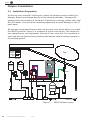
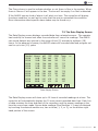
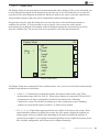
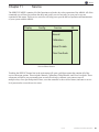
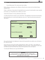
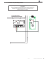
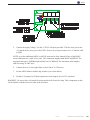
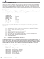
We strongly recommend that you plan out the pool room layout before you install
the AK600 controller. Figure 1 is a sample of a pool room layout. Your layout will
vary depending on your equipment, the size of your room, etc. It is important to
mark and plan all electrical and plumbing connections before making changes to
the existing system.
Power
Signal
Water
gas
Chemical
Acid
Pool
Chlorine
Flow
Flow
Flow
Flow
Flow
Flow
Figure 1.
10
Pentair Water Commercial Pool and Aquatics™
12-15-07
drain Flow
AK600 System layout
AK600
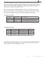
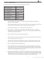
The modular design of the AK600 allows the connection and control of any device
to any relay. Determine which device you want to connect to each relay or input
before you begin the installation process. For AK600’s controlling multiple bodies of
water, it will be helpful if the configuration for each body of water is the same: i.e.
your ph pump is always connected to relay 1.
below are Relay and Input mapping Tables to help in the planning and organization of new installations. Use these tables to record your input and relay configurations. This information will be valuable when the system has an alarm, or when
you choose to upgrade the system to control an additional body of water.
Example Input Table
INPUT NAmE
SYSTEm NAmE
INPUT USEd FOR
Ph1
Kids Pool
Flow cell measurement for acid feed control
ORP1
Kids Pool
Flow cell measurement for Cl feed control
Temp1
Kids Pool
Flow cell measurement for heater control
Fl1
Kids Pool
Flow cell magnet indicates flow
Example relay Table
RElAY
SYSTEm NAmE
RElAY USEd FOR
VOlTAgE
1
Kids Pool
Acid Feed Pump
115VAC
2
Kids Pool
Erosion Feeder Solenoid
24VAC
3
Kids Pool
4
Kids Pool
heater Control
dry
To simplify the installation process, Acu-Trol manufactures the AK600 with default
factory relay and input configurations. The factory default settings are stored in
the controller and can be reloaded at any time.
12-15-07
Pentair Water Commercial Pool and Aquatics™
11
AK600
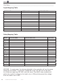
Site Name _________________________________________________________
Input Mapping Table
INPUT NAmE
SYSTEm NAmE
INPUT USEd FOR
relay Mapping Table
RElAY
SYSTEm NAmE
RElAY USEd FOR
VOlTAgE
1
2
3
4
5
6
7
8
9
10
11
12
13
14
15
16
VOLTAGE: In most cases, the devices attached to the controller will use the same
voltage as the AK600. A controller configured to use 115 VAC will not be able
to run devices requiring 230 VAC, and vice versa. The AK600 relay modules will
switch the module’s voltage to the load to turn it ON and disconnect the voltage
from the load to turn it OFF.
12
Pentair Water Commercial Pool and Aquatics™
12-15-07
AK600
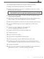
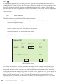
2.2 Installation Overview
The following steps are required to completely install an AK600PS:
1. Identify new and existing equipment to be connected.
2. decide if the sensors will be in-line, in a separate by-pass line, or if the
AK1200 flow cell will be used.
CAuTION
If the AK1200 is used, the input water maximum pressure is 25 pSI.
3. Determine the supply voltage, 115 VAC or 230 VAC, and set the supply
voltage switch as necessary.
4. Determine if the control to the equipment uses the same voltage as the
supply voltage. All controlled equipment must be compatible.
5. Determine the plumbing locations for the flow cell bypass inlet and outlet.
6. mount the AK600PS away from direct sunlight and on a flat vertical
surface.
7. Connect the supply voltage with main breaker off
(must be a separate dedicated circuit gFCI).
8. If using an AK1200 flow cell install the bypass now.
9. Connect the sensors.
10. Test the plumbing for leaks.
11. Turn on/plug in the AK600PS for the first time.
12. Test the equipment, using the AK600PS manual relay mode.
13. Calibrate the probes, then recalibrate as the probes acclimate to the
water. Acclimation can take as little as two hours or as long as 24 hours.
14. Program the AK600PS.
15. Call or visit the controller over the next few days to insure the system is
balanced and in control. Fine-tune the setup if necessary.
12-15-07
Pentair Water Commercial Pool and Aquatics™
13
AK600
2.3
Mounting the AK600
Select a location for mounting the AK600 that will meet the following conditions:
• At least ten (10) feet from open water.
• Close enough for the supplied power cord to reach the supply voltage.
wArNING
proper and safe operation requires an earth ground connection.
• Supply power must be routed to the AK600 in accordance with the
applicable codes in the area; the supplied cord is not code in some areas. Please
have a licensed electrician perform any and all electrical.
• The installation surface must be solid and vertical.
do not mount the controller in a horizontal position.
WARNING
Keep the AK600PS out of direct sunlight and inside a room if possible, a
shade screen should be used for outdoor installations.
•
Maintain adequate clearance for opening the enclosure door.
• The environment should be free of chemical fumes and excessive heat.
Do not install the AK600 controller in areas that exceed 110° Fahrenheit.
• Mount the controller as far as possible from potential sources of electrical interference. To mount the AK600 to your chosen surface:
• Attach the four (4) mounting
brackets to the back of the controller,
using the supplied hardware.
• Hold the controller against the
mounting surface with the lid closed
and mark the four (4) holes located
in the top and bottom bracketsconnected to the controller.
• Prepare holes as necessary and
secure controller.
• Make sure the controller box is
not
14
Pentair Water Commercial Pool and Aquatics™
12-15-07
AK600
2.4 plumbing Installation
Every AK600 installation will be different depending on the type of equipment you
have, the plumbing that already exists, and the amount of available room for the installation. It is strongly suggested that you create an installation plan for the plumbing and the controller. This section gives the basic principles to be applied for any
specific installation, which are listed as follows:
•
Turn OFF all equipment.
•
Determine a suitable location for the AK1200 Flow Cell.
(See flow cell manual for detailed setup instructions).
•
Securely mount the AK1200.
•
Locate where the water will be supplied from and returned to each AK1200.
•
Install the supply and return lines for each AK1200.
•
Locate the chemical injection points.
•
Prepare and install the chemical injectors.
•
Install the chemical storage containers.
•
Install the sensors.
•
Turn on the main circulation pump.
•
Check for leaks.
•
Verify flow switch magnet in AK1200 is being pushed up with the flow.
• Verify the AK1200 is not under any vacuum by opening the bottom sample valve.
A stream of water should be released. If no water is released, and you see bubbling
around the sample port, close the AK1200 outlet valve until the bubbling stops and a
stream of water is released from the sample port.
• Leave the 1200 flow cell full of water to allow sensors to begin acclimating to system water.
•
Call or visit several times over the next few days to verify system integrity
wArNING
To ensure that your installation complies with all local codes have
a licensed plumber complete all plumbing installations.
12-15-07
Pentair Water Commercial Pool and Aquatics™
15
AK600
2.5 Electrical Installation
Each electrical installation for the AK600 will be different depending on the electrical codes in your local area, the types of devices you want the AK600 to control,
and the existing wiring in your facility. While we are unable to provide you with
specific advice regarding your installation, we do suggest that you follow these
basic steps.
•
Identify the new and existing equipment to be connected.
• Determine the supply voltage, 115 VAC or 230 VAC and if an external ON/OFF
switch is necessary.
•
Determine if the equipment control voltage and supply voltage are the same.
•
Connect the supply voltage. (Must be on a separate dedicated GFCI circuit)
•
Connect each load to the corresponding relay.
• Connect the sensors. Route the sensor wires through the three small strain
reliefs’ into the controller and install them in to the appropriate connectors in the
sensor module.
•
The polarity (+ and -) of the pH and ORP sensors must be observed.
•
The ORP sensor (+) is marked ORP+
•
The pH sensor (+) is marked pH+
•
The green leads are (-) polarity.
•
Do not cut the sensor wires.
• After the wiring is complete, close the panel and tighten the strain reliefs’. Wrap
and tie any excess wire into a coil.
•
Do not stuff excess wire inside the controller.
•
Test the equipment, using the AK600 manual relay mode.
!
CAuTION
To ensure compliance with all state and local codes, have a
licensed elecctrican perform any and all electrical work.
16
Pentair Water Commercial Pool and Aquatics™
12-15-07
AK600
2.6 Input Voltage Selection
The AK600 will operate on input voltages of 115 VAC or 230 VAC. The factory default
input voltage is set for 115 VAC. The supply power is most commonly used to power
the feed pumps and other external loads. If all the loads are 115 VAC then use 115
VAC and if all the loads are 230 VAC then use 230 VAC as the input voltage. It is also
possible to have one relay board powered with 115 VAC and another relay board with
230 VAC. This is beneficial when there is a mix of load voltages. If you need to have
your relay boards use different input voltages please contact your local Acu-Trol dealer for further instructions and assistance.
WARNING
If the AK600 is conntected to 230 VAC the voltage switch on the relay board
must be changed to 230 VAC.
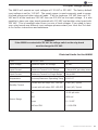
Electrical Limits for the AK600
ITEm
dESCRIPTION
lImIT
Input Voltage
Maximum Input AC Voltage
250 VAC
Input Current
Maximum Current for All Relays
10 Amps VAC per relay board
Input Current
Maximum Current for Single Relays
5 Amps VAC
Temperature
Minimum/Maximum Operating Temp 30-110 ºF
Standby Current
Sensor Range
Current with all relays OFF, lEd ON
90 mA (AC) Typical
Current with all relays OFF, lEd OFF 65 mA (AC) Typical
ph
4.2-9.8 ph units
ORP
0-999 mV
Temp
32 – 212ºF
AKColor PPm
0 – 9.99 PPm
12-15-07
Pentair Water Commercial Pool and Aquatics™
17
AK600
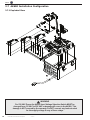
2.7 AK600 Installation Configuration
2.7.1 Exploded View
!
WARNING
For 230 VAC Power the AK600 Input Voltage Selection Switch MUST be
changed from 115 VAC to 230 VAC or damage will occur to the AK600. This
damage is NOT covered by the warranty. Do NOT connect any load not rated
for the supply voltage to any of these relays.
18
Pentair Water Commercial Pool and Aquatics™
12-15-07
AK600
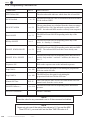
2.7.2 parts List
dWg. # PART #
dESCRIPTION
1
Enclosure, AK600, lid, overlay, and hardware
2
714000720
Kit, AK600, Power Switch
3
755000190
Cord, Power, AK600, gFCI ** Not permitted in all areas**
4
714000110
Strain Relief, 5/8”, liquid tight
5
714000100
Strain Relif, 1/2”, liquid tight
6
724000120
PCb, Relay board, AK600, 4 NO
7
724000130
PCb, Sensor, ph, ORP, Temp, 3 switch
8
724000090
PCb, motherboard, AK600
9
724000100
PCb, Interface board, AK600
10
724000110
display, Touchscreen, AK600
11
Ribbon Cable, AK600
12
Relay board mounting screws
13
724000050
Socket, Relay NO(110/24/dry)
14
714000120
Kit, latch, Integra Enclosure
Not Shown
725000020
modem, Standard
735000010
modem, Wireless
724000150
PCb, Sensor, Pressure, Temp
724000160
PCb, Sensor, ph, ORP, Cond, Temp
724000180
PCb, Sensor, ph, ORP, Color, Temp
724000190
PCb, Sensor, ph, ORP, Color, Cond, Temp.
724000060
Socket, Relay, NC (110/24/dry)
12-15-07
Pentair Water Commercial Pool and Aquatics™
19
AK600
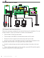
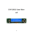
2.7.3 AK600 Inputs & Outputs
2.8 Chemical Feed pump Installation
Follow the instructions included with the chemical feed pump for installation if it is not
already installed. Follow the list below for location recommendations:
•
Mount at least 10 feet from open water.
•
Close enough to the AK600 for the feed pump power cords to reach.
•
Remove the electric plugs from the feed pumps and strip the ends.
•
Route the power cords to the AK600 through the lower fittings and attach to the
appropriate relay terminals on the appropriate relay module boards.
•
Conduit or external plugs can also be used (according to the codes in the local
area).
•
When installing metal conduit into the controller, a ground LUG should be used to
connect the conduit to the relay board ground.
20
Pentair Water Commercial Pool and Aquatics™
12-15-07
AK600
2.9 Solenoid Location
For a sanitizer erosion feeder a solenoid valve will be required to control the flow
through the feeder. The solenoid should be installed on the inlet side of the feeder to
minimize chemical contact with the internal parts of the solenoid, unless otherwise
specified by the feeder manufacturer. The solenoid may have an inlet side and an
outlet side; make sure the direction is correct. Special fittings for the solenoid may
need to be obtained.
The control relay can supply a variety of voltages depending on the relay module installed (115, 230, 24 VAC or switch only). In order to support a 230 solenoid, a 230
supply voltage must be provided.
2.10 Erosion Feeder Location
To install a sanitizer erosion feeder follow the instructions included with the feeder for
installation if it is not already installed.
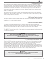
2.11 Flow or pressure Switch
It is highly recommended that a flow or pressure switch be used to prevent the
AK600 from feeding chemicals if the main pump is OFF. Any flow switch used in this
manner should be closed when flow is present and open when flow is absent.
The AK1200 flow cell has a built in flow switch that protects against feeding chemicals
in a NO flow condition.
WARNING
When using anything other than Acu-Trol switch devices the
flow switch must not suppply any voltage to any switch inputs or damage to
the controller may occur.
!
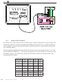
2.12 using An Existing Main Timer
After the AK600 has been mounted cut the plug off the end of the supplied cord and
strip the wires. Route the wires to the timer box and use an electrical strain relief
connector to fasten the power cord to the box at the entry point. When
using 115 VAC, connect the hot and neutral to the corresponding hot and neutral on
the switched side in the timer box. For 230 VAC connect the white and black wires to
the two hot wires in the timer box. For 230 VAC the AK600 will use both wires as hot
for two (2) phase 230 VAC or one wire as hot for single phase 230 VAC.
! CAUTION
Only use proper wires and conduits for these conditions in accordance
with all local codes and regulations.
12-15-07
Pentair Water Commercial Pool and Aquatics™
21
AK600
Chapter 3 hardware
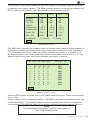
3.1
Modules
modules are the electronic controls and components that make up the AK600. Each
module has a specific function or functions that tell the controller what information
to accept, and what information to display. The modular design of the AK600 enables it to interface with many types of modules including Sensor, Communication,
Relay, memory and Remote.
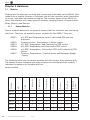
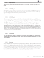
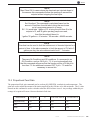
3.1.1
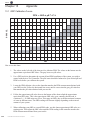
Sensor Modules
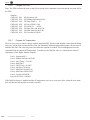
Sensor modules determine the types of sensors that the controller can receive signals from. There are six available sensor modules for the AK600. They are:
AK610:
ph, ORP and Temperature control, calculated PPm can also
displayed.
Pressure control, Temperature, 5 Switch inputs.
pH, ORP, Temperature, and Conductivity/TDS control
ph, ORP, Temperature and Colorimetric PPm control
pH, ORP, Temperature, Colorimetric PPM and Conductivity/TDS
control.
Pressure, Temperature, 5 Switch inputs and backwash Stager
Control
AK612:
AK613:
AK615:
AK616:
AK617:
`
AK612
AK613
1
1
1
AK615
1
1
1
AK616
1
1
1
AK617
22
Pentair Water Commercial Pool and Aquatics™
12-15-07
1
1
5
1
1
2*
1
1
1*
1
1
1*
1
5
Backwash
Stager
1
Flow Rate
1
Pressure
Flow Switch
1
Temperature
ORP
1
Conductivity
pH
AK610
Colorimetric
Module
The following table lists the sensor modules with the sensors they interface with.
The sensor number indicates how many sensors are included with the module; *
indicates the sensors not included with the
sensor module.
2*
4
4*
2
AK600
3.1.2 Communication Modules
The AK600 has the ability to work with several types of communication modules. The
controller can communicate with a PC through an RS232 cable, a standard modem, or
a wireless modem. The AK600 can also communicate directly with a serial printer, and
certain remote modules. most of the communication modules can be installed simultaneously; however the corresponding hardware will only allow one
communication device to function at a time.
AK620: High-speed voice modem. This modem has only the modem connector, and no otherconnectors
AK621: A high speed voice modem with the addition of two more com-ports.
These additional comports include an additional serial RS232 interface for printers
and an RS485 for remote module connections.
AK622: Two additional communication ports. These additional com-ports include an additional serial RS232 interface for printers and an RS485 for remote
module connections. No modem is included in this communication module.
Wireless Modem: The wireless modem allows the controller to be accessed over
the internet from any PC. Wireless modems are a perfect solution for installations
without phone lines. Please note that the wireless modem and the standard modem
can not be installed in the same controller.
3.1.3 Memory Module
The memory module expands the data recording capabilities of the AK600 and enables the controller to be accessed from any touch tone telephone.
The AK600 memory module expands the size of the data log in the controller. It enables the controller to record each time one of the 16 available relays turns on or off,
and the corresponding time and date. The memory module will hold up to 4500 lines
of relay state change data.
The AK600 Voice module is included in the memory module. The memory module is
required for voice operation of the AK600. The voice module enables communication
with the controller from any standard touch tone telephone. This module allows the
operator to hear the chemical readings and relay on and off times over the phone. He
or she can then make any necessary adjustments to the controller’s programming using a simple menu.
Note: For more information on the operation of memory, communication, or sensor
modules please refer to the PROgRAmmINg gUIdE.
wArNING
removing the memory chip from the board will erase all the data
stored on the memory module.
!
12-15-07
Pentair Water Commercial Pool and Aquatics™
23
AK600
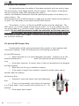
3.1.4 Relay Modules
The AK 600 is able to automate nearly any device in your pump room. The controller uses a relay module to turn electricity to the device on and off. Each AK600 can
control up to 16 relay modules. Each relay module can control one device. All relay
modules must be installed in a relay board. A relay board can hold 8 relay modules.
An AK600 can hold two relay boards. Relay boards can be installed at the factory, or
added later in the field.
Relay modules are available in seven different models. The type of relay module used
depends on the load requirements of the device you wish to control with the relay
module. To determine the load requirements, please consult the instruction manual or
the device manufacturer. Any combination of the seven models of relay modules can
be installed in the eight available slots on a relay board, so long as the combination
does not exceed the combined maximum current for the relay board. The combined
maximum current for any individual relay board is 10 amps. The combined maximum
current for two relay boards is 20 amps. The maximum relay current for the relay
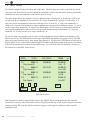
board is 5 amps when switching 115 VAC and .5 amps when switching 24 VAC.
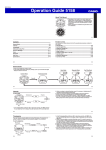
Factory Setting
for input power
115 VAC
Setting for
24VAC
Dry (Switch)
White = No Jumper
Grey = Jumper
•
drY CONTACTS: These relays act as a dry contact switch only and have no
connection to the input VAC. The relay ratings are 5A and 250 VAC
Figure 2. Relay Module
•
115 VAC Normally Closed: These relays supply the input voltage to the load
when the relay is in the “OFF” mode. Note that both VAC inputs are controlled by the
relay. The relay ratings are 5A and 250 VAC.
•
115 VAC Normally Open: These relays supply the input voltage to the load
when the relay is in the “ON” mode. Note that both VAC inputs are controlled by the
relay. The relay ratings are 5A and 250 VAC.
24
Pentair Water Commercial Pool and Aquatics™
12-15-07
AK600
•
115 VAC SpdT: These relays are hardwired selectable to be either NO (Normally Open) or NC (Normally Closed) switching of the input voltage. They are always
powered, and the wiring will dictate whether the power flows in the on or off position.
The relay ratings are 5A and 250 VAC. The neutral is common for both NO and NC.
•
24 VAC Normally Closed: These relays supply 24 VAC to the load when the
relay is in the “OFF” mode. Note that both VAC inputs are controlled by the relay.
The relay ratings are 5A and 250 VAC.
•
24 VAC Normally Open: These relays supply 24 VAC to the load when the relay is in the “ON” mode. Note that both VAC inputs are controlled by the relay.
The relay ratings are 5A and 250 VAC.
•
24 VAC SpdT: These relays are hardwired selectable to be either NO (Normally
Open) or NC (Normally Closed) switching of the 24 VAC. They are always powered,
and the wiring will dictate whether the power flows in the on or off position. The relay
ratings are 5A and 250 VAC. The neutral is common for both NO and NC.
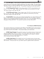
3.1.4 remote rS485 Modules
The remote modules are connected to the AK600 using RS485 serial communication
and require the appropriate communication module. These modules can be located
up to 4000 feet from the AK600. The present modules are as follows:
AK245 Quad Output: This module has four (4) isolated outputs of which each
can be configured for 0-5VDC, 0-25mA, or 4-20mA: Each output on this module is
isolated and the 4-20mA includes power. These outputs can be used for variable
loads and for remote monitoring equipment, including
chart recorders, pumps, and valves.
AK250 Quad Input: This module has four (4) isolated inputs of which each
can be configured for 0-5VDC or 4-20mA input. These inputs can be used for sensors
and controls. There are also four (4) switch inputs for general switch operations.
12-15-07
Pentair Water Commercial Pool and Aquatics™
25
AK600
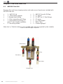
Chapter 4 AK1200 Flow Cell
4.1
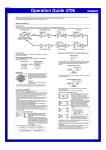
AK1200 Flow Cell
Remove flow cell from shipping carton and make sure all parts are included with
AK1200 flow cell.
•
•
•
•
•
•
1 – AK1200 Lid
1 – Flow switch magnet
1 -Sample barb fitting
1 - Filter assembly w/ O-Ring
1 - Flow switch w/ O-Ring, 2’
and 10’ wire lengths available.
2 - Mounting screws
•
•
•
•
•
•
•
1
3
4
2
1
1
1
– AK1200 Jar with O-Ring
- ¼” Valves.
- ¼” NPT by ½” flex fittings.
- ¼” plugs.
- ¼” Close Nipple
- Teflon Tape
– Pressure gauge*
Note that ½” flexible tubing is not included and must be supplied by the installer.
* Use of Pressure guage is Optional
Flow Switch
Filter
Exit Valve
Inlet Valve
Sample Port
26
Pentair Water Commercial Pool and Aquatics™
12-15-07
AK600
4.1.1 Flow Cell Assembly
WARNINg
dO NOT OVER TIghTEN FITTINgS ON gRAY FlOW CEll TOP AS ThIS mAY
bREAK OR CRACK FlOW CEll TOP.
!
1. Wrap all four flex fittings with Teflon tape. Install two flex fittings into two ball
valves.
2. Wrap barb fitting with Teflon tape. Install barb into remaining ball valve.
3. Wrap both ends of the close-nipple with Teflon tape. Install into the filter assembly using (either end OK). hand-tighten only.
4. Install one ball valve into the filter.
5. Install the filter and remaining ball valves as shown in the figure.
6. Verify that the flow switch magnet is in the flow cell tube with the large, or hat
end pointing down.
NOTE: Wrap fittings only twice around with Teflon tape.
4.1.2 Flow Cell Mounting
1.
2.
3.
4.
5.
6.
7.
8.
9.
10.
11.
12.
13.
14.
15.
Select a suitable location for the flow cell meeting the following
recommendations:
The flow cell location should be within ten (10) feet of the controller so the
sensor wires will reach.
The sensors should be away from direct sunlight, as this may affect the
readings.
The location should be where some water spillage will not damage anything.
Preferably below the level of the controller.
Securely mount the bracket to wall using the two supplied screws.
Securely fasten all electrical, water and chemical lines.
locate chemical feed pumps and chemical storage tanks in a safe and
secure area.
Check filter daily for debris buildup and clean as needed.
To clean filter, turn both flow cell inlet and exit valves OFF, (see caution in
paragraph above) remove filter cover and filter, being careful not to lose seal.
Clean stainless steel filter and return to housing being careful to seat it
properly. The filter screen can be easily damaged if seated improperly when
the cap is installed.
Maximum operating pressure = 25 lbs.
Extreme pressure variances may affect readings and can cause damage to
the sensors.
Avoid installing the outlet before the main pump as the vacuum may damage
the chemical sensors.
Only inject chemicals on the outlet side of the AK1200.
Do not over tighten fitting on flow cell top.
12-15-07
Pentair Water Commercial Pool and Aquatics™
27
AK600
4.1.3 Inlet and Exit Lines
1.
It is essential that the supply line be at a higher pressure than the discharge
line so the water will flow through the cell at a steady rate in the right direction.
Installing a ball valve in the main circulation line may be required if the pressure is
too low.
2.
Inlet should be installed after filter and before heater.
3.
Exit should be installed after heater and as far away from any equipment as
possible.
4.
Drill and tap at above locations with 7/16” drill and 1/4” NPT tap. Choose a
location on a fitting where the pipe enters so you are drilling through both the pipe
and fitting to get maximum depth of thread.
5.
Install ¼” NPT by ½” flex fittings then route inlet and exit lines.
4.1.4 Sensors
1. Keep pH and ORP sensors wet at all times, install the sensors into the flow
cell. Hand-tighten only and save caps for future use, fill flow cell with water. The
sensors have O-Rings and don’t require Teflon tape.
2. Route the flow switch wires into the controller through the strain relief and
connect to the controller. One wire (either one) to ground and one to the appropriate input switch.
! CAUTION
The flow switch is a dry contact only. (No Current)
Use with any other brand controller VOIDS WARRANTY
3. Route the chemical sensors into the controller through the strain relief and
connect to the controller. The sensor wires are labeled and the plus and minus polarity must be observed.
4. Turn the main pump on and open the valves to test for leaks and the free
movement of the magnet. The Magnet must be all the way up in order to close the
flow switch. 1/4 GPM will push the magnet all the way up.
WARNING
Make sure that all pumps are OFF before drilling into pipes.
!
!
WARNING
Never turn chemical feed pumps on when both
flow cell valves are closed..
28
Pentair Water Commercial Pool and Aquatics™
12-15-07
AK600
Chapter 5 Sensors
The AK600 can accept readings from a wide variety of sensors. The sensors that the
AK600 is able to read depend on the sensor module installed in the controller. Each
sensor has its own unique circuitry that is connected directly to the micro-controller
for measurement. The pH, ORP, PPM and conductivity sensors are isolated from each
other and from the input power. Isolation of each sensor ensures more accurate
measurements.
The AK600 measures the following sensor measurements with the listed characteristics:
1. ph
• Range: 4.22 to 9.78, ±0.02.
• This measurement is temperature compensated.
2.
ORP
• Range: 0 to 999 mV, ±1mV.
3.
Conductivity
• Range: 0 to 9999 uS.
• This measurement is temperature compensated.
4.
Temperature
• Range: 32 to 212 °F, ±0.02.
5.
Flow Switch
• This input measures if a switch is open or closed.
6.
Flow Rate (1 to 6 inputs);
• Range: 0 to 5000 gallons per minute.
7.
Pressure (1 to 4 inputs),
• Range: 100 PSI, ±0.1PSI.
• The AK600 has 12VDC available to power the sensor.
8.
AKColor Colormetric PPm Sensor
• Range 0 to 9.99 PPM
!
WARNING
Sensors are shipped with a protective cap covering the electrode tip to protect the
sensing element. Sensors should be kept in the protective cap until ready for installation, if the sponge in the cap becomes dry, wet it with tap water. During shipment,
air bubbles may have entered the electrode, carefully shake the electrode downward
(like a thermometer) to dispel the air from the sensing elements inside the
electrode. Before using the sensor, remove the cap.
12-15-07
Pentair Water Commercial Pool and Aquatics™
29
AK600
5.1 ph and Orp Sensors
ph electrodes sense the acidity of the water and work with any acid or base.
The blue bands on the cables identify the ph sensors. Each sensor is also identified on the sensor body. ORP electrodes are used to
monitor the Oxidation-Reduction Potential (sanitization quality of the water) of a
given solution. The
sensing element of the ORP electrode is made of a precious metal such as platinum
or gold. The red bands on the cables identify ORP sensors.
The polarity (+ and -) of the pH and ORP sensors must be observed. The
ORP sensor (+) is color-coded red and the pH sensor (+) is color-coded blue, and
the green leads are (-) polarity coded. Leave excess wire outside the controller enclosure. do not stuff excess wire inside the controller as this may cause excess strain on sensor and relay connections. do not cut the sensor wires.
If the cable is longer than needed, it should be coiled neatly and attached under
the controller enclosure.
5.2 ph and Orp Sensor Care
Contamination of the sensing elements often results in slow response and
inaccurate readings. Clean the elements by the following procedures:
ph and ORP sensors
• Wash electrode tip in a liquid detergent and water. Carefully use a soft
bristled toothbrush to
wash the electrode tip and white sensing
ring.
• Rinse after cleaning. To install, place in flow cell according to the diagram
and hand tighten.
• Make sure the O-ring is installed on sensor.
• If the cable is longer than needed, it should be coiled neatly and attached under the cabinet.
ph Sensors Only
• Attempt to clean the sensor with liquid detergent
first.
• If this is not successful, swirl the tip of the sensor
in a 5 parts water 1 part muriatic acid solution for 10 - 20
seconds.
• Rinse again and reinstall.
30
Pentair Water Commercial Pool and Aquatics™
12-15-07
AK600
5.3 Flow Sensors
The AK600 can accept information from two types of flow sensors:
1) Flow switches
2) Digital flow sensors.
Each AK610, 611, and 613 sensor module has three (3) flow inputs. The first flow
input, FS1, must be a flow switch. The Second and third flow inputs, FS2 and FS3,
can be either a digital flow sensor or a flow switch.
The AK612 and 617 pressure sensor modules have five flow inputs and are primarily used for backwash operations. Each of these five flow inputs must be a flow
switch. This sensor module is not compatible with digital flow sensors.
When installing a digital flow sensor, follow the instructions that come with the
sensor. Most digital flow sensors will have three different colored wires. One will
be a positive wire, which provides the supply voltage for the sensor.
1. The wire with the positive charge should be installed in the connection
on the sensor module labeled +12.
2. The second wire will be a ground or negative voltage wire. This should
be connected to the ground connection on the sensor module.
3. The third wire, the signal, should be connected to either the FS2 or FS3
slot.
5.4 pressure Sensors
The AK612 or AK617 sensor modules have the ability to receive signals from up to
four amplified pressure sensors. The AK600 can accept readings from any pressure sensor that has an output of 0.500 volts at 0 PSI, and 4.50 volts at 100 PSI.
Pressure measurements can not be calibrated.
When installing a pressure sensor, connect the red wire to +12, the black wire to
the ground and the white wire to the pressure input on the AK612 or AK617.
5.5 Finishing your Installation
To following outlines some finishing touches needed for any good installation.
1. Verify the programming in the AK600
2. balance the water to your desired set point.
3. Turn the AK600 on, and allow it to begin automatically controlling
the water balance.
4. Calibrate all sensors to the balanced water.
5. If the sensors have not finished acclimating to the system water,
recalibrate the sensors the following day.
6. Call or visit several times over the next few days to fine-tune the setup
and programming.
7. Submit the registration card for your controller to Acu-Trol.
12-15-07
Pentair Water Commercial Pool and Aquatics™
31
AK600
Chapter 6 Operations
6.1 Introduction
This PROGRAMMING GUIDE introduces and describes all the available screens and
menus of the AK600, from navigating and initializing the screens to programming
and customizing specifications. If you have any questions after reading through
this manual, please contact your local Acu-Trol dealer for further assistance.
6.2 Navigating in the AK600
The AK600 has a touch screen display, similar to a PdA or an ATm machine. All of
the menus in the AK600 are accessed using this touch panel display. The touch
screen display should be operated using the plastic stylus included with the controller. hold the stylus as you would an ordinary pen, being careful not to touch
the display with fingers. Do NOT exert pressure when using the stylus or you may
damage the display.
WARNING
Using a pen or other sharp object on the touch screen
will damage the display.
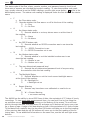
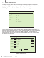
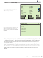
There are three main menu selections in the AK600, dISPlAY, CONFIg, and
SERVICE. All other menu selections are contained in these three main menu choices. To Access one of these three main menus, touch the menu title with the stylus.
Note: The small xx on the top right-hand side of the screen can be used to back
out to the previous screen. Touching the left corner (hidden symbol) will exit out
all the way back to the main menu.
$ISPLAY
#ONFIG 3ERVICE
3PECIFIC
$ATA
3UMMARY
-034IMERS
)NFORMATION
32
Pentair Water Commercial Pool and Aquatics™
12-15-07
88
AK600
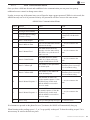
6.3 Selecting Items
The AK600 offers the option to make changes or to customize the screens.
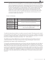
There are several methods for selecting menu items in the menu screens.
The System menus are accessed by touching the menu item title directly on the screen.
In this manual, System menus are always in bOld CAPITAl lETTERS. There are three
system menus in the AK600, dISPlAY, CONFIg, and SERVICE.
Each main menu contains a series of related sub-menus. Sub-menu titles will always be
in bold letters. To access these sub-menus, touch the sub-menu title with the stylus.
Some of the sub-menus include on-screen buttons. On-screen buttons are indicated in
this manual in bold Italic highlighted letters. On-Screen buttons are used to organize
large sub-menus into categories. Touching an on screen button will open up a smaller
section of a sub-menu. All of the items contained in a button menu will be related to a
specific part or function of the controller.
A few of the buttons in the AK600 are multifunction or toggling buttons.
These buttons are used in cases where there are a limited number of specific choices for
a certain setting or program parameter. Pressing one of these buttons changes the button label as well as the current controller setting. multifunction or toggling buttons will
be shown in Regular Italic highlighted letters.
When there is a list of 7 or more items to select from, a set of directional arrows
will appear at the bottom of or on the right side of the screen. These arrows are used to
scroll through the list of choices. The current item will be highlighted as you scroll. When
directional arrow keys appear at the top right of the screen they are used to access the
previous and/or next screen.
6.4 Changing Item Values
The AK600 offers several ways to change or input information in the controller. The
method you will use to change a value will depend upon the type of value it is and the
number of choices available for that variable.Some items will have a limited number of
specific choices. In this situation a Change button will appear at the bottom right hand
corner of the screen. Once you highlight the item you wish to change using the directional arrows, pressing the Change button will scroll through the choices for that item. Once
you reach the choice you wish to select, use the Enter or OK button to exit and save your
changes.
Other items have a longer list of specific choices. For these items you will be shown the
entire list of choices, along with directional arrows to help you scroll through the choices.
Once the choice you wish to select is highlighted, press the Enter or OK button at the
bottom of the screen.
12-15-07
Pentair Water Commercial Pool and Aquatics™
33
AK600
many of the settings in the AK600 are completely user selectable. For these
setings you may enter any combination of letters, numbers, and symbols. The controller will generally prompt you for a certain number of characters, and will reject
characters that do not meet certain logical standards for that specific setting. Any
setting that requires a user specified value will automatically launch the alphanumeric keyboard.
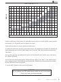
6.4.1 The Alphanumeric Keyboard
The AK600 includes an alphanumeric keyboard with capital letters, numbers
and special characters. If the item being changed needs this keyboard it will appear and the current value or text will be displayed, ready for editing. The correct
format for the value being entered is shown on the guide line above the text entry
line.
To edit any character, touch the character with the stylus. Then use the alphanumeric keyboard to enter a new character or change the character above the
underline. Use the Enter button at the bottom of the screen to save your changes.
The top line on the alphanumeric keyboard screen holds several shortcut
buttons. The "CAPS button is used to change from capital to lower case letters.
When "CAPS" is displayed, the alphanumeric keyboard will display capital letters.
When "caps" is displayed, the alphanumeric keyboard will display lower case letters. Touching the "CAPS" button with the stylus will toggle between the two choices. The "d" button can be used to delete or clear a character. The "I" button will
insert a space for a character in between two existing characters. The ">" and "<"
buttons are used to move the cursor right and left while editing the characters.
The Enter button saves your changes and closes the alphanumeric keyboard.
If the values you have entered do not match the required format, an error message will appear. To return to the alphanumeric keyboard, touch the screen with
your stylus. The Cancel button closes the alphanumeric keyboard without making
any changes to the current settings and values. Once changes have been saved
the only way to return to the original value is to re-enter it.
CAPS
x d l < >
Enter Value (#.##)
-> n
Q
W
E
R
T
Y
U
I
O
P
@
&
7
8
9
A
S
D
F
G
H
J
K
L
:
-
=
4
5
6
Z
X
C
V
B
N
M
,
.
/
#
?
1
2
3
0
.
Cancel
34
Pentair Water Commercial Pool and Aquatics™
Space
12-15-07
Enter
AK600
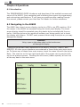
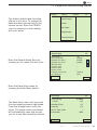
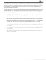
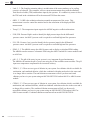
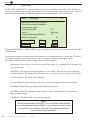
6.5 Initializing the AK600
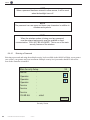
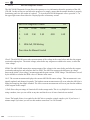
Anytime the controller is turned on, the AK600 will perform a brief check of its internal systems and load variables into memory for operation. After this check the controller will open the initialization screen and display the results of this check.
The initialization screen displays information about the controller. It will tell the operator the model of the controller, the version of firmware the controller is using, and display a list of detected hardware. This list may include modems, printers, sensor cards,
and memory modules; the exact list is determined by the
components in your controller. If the external memory module was previously installed and is now not detected, an error message will be displayed in the initialization
screen.
Controller
Model
List of
detected
hardware
Firmware Version
& Date
!+$ 0ROGRAMMABLE#ONTROL
)NITIALIZING
%XT2!-$ETECTED
(IGH3PEEDMDEMDETECTED
0RINTER)NSTALLED
Initialization Screen
Once all initialization tests have been passed, the controller will automatically open
the dealer Information screen.
!CU4ROL-ULTI3YSTEM#ONTROL
88
+EMPER2D
!UBURN#!
WWWACUTROLCOM
Dealer Information Screen
12-15-07
Pentair Water Commercial Pool and Aquatics™
35
AK600
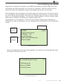
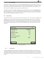
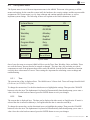
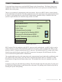
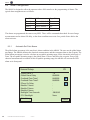
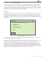
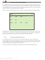
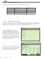
Chapter 7 The System Menu
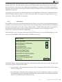
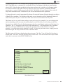
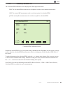
Once the controller has identified itself, it will open the system menu screen. The system menu screen displays the unique serial Id number for your AK600. It also displays the current time, day and date. The mPS status for the relays is also displayed
on the system menu screen. This information will tell you if any relays have been
changed to manual operation only, turned off, or globally disabled.
$ISPLAY
Serial
Number
Time &
Date
General
Relay Status
#ONFIG 3ERVICE
3.
4UESDAY
-033TATUS
(OAv.ORELAYSIN(ANDMODE
H/A.OREALYSIN/FFMODE
'$.ORELAYS'LOBALLY$ISABLED
/..ORELAYS/.
./6OICE&ILE
07$
System Menu Screen
NOTE
If the external memory is installed, but the voice file is missing or
corrupt, the messate "No Voice FIle" will be displayed on this screen.
NOTE
The serial number, time day and date may be replaced with various
warning messages and not always displayed on the
system menu screen.
The AK600 has many features to protect the security of your pool or spa. Your controller can be programmed with up to 7 passwords, providing 4 access levels. The
default factory setting for the AK600 does not have any passwords. You may choose
to program passwords as a part of your set up. Once a
password or passwords have been programmed, no one will be able to progress beyond the display menu without entering the password. To enter a password, press the
PWd button on the bottom right hand corner of the system menu screen. The alphanumeric keyboard will automatically open for you to enter the
password.
There are three menu headings on the System menu screen. These three menus,
dISPlAY, CONFIg and SERVICE, are opened by touching the appropriate heading
with your stylus. After touching one of the three system menu headings, a drop down
menu will appear and display the sub-menus underneath each system menu.
36
Pentair Water Commercial Pool and Aquatics™
12-15-07
AK600
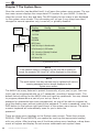
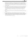
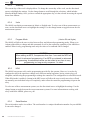
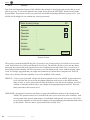
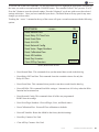
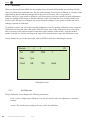
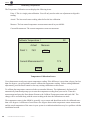
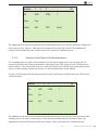
7.1 The display Menu
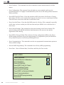
The DISPLAY MENU has five sub-menus, Specific, Data, Summary, MPS Timers, and
Information. Each of these sub-menus will help you to view the data captured by the
AK600.
•
•
•
•
•
AK600.
The Specific sub-menu displays an overview of chemical levels and feed
times for each pool or spa controlled by the AK600
The Data sub-menu displays the data recorded from the sensors at a set
interval.
The Summary submenu displays the chemical levels for up to three pools
or spas
The MPS Timers submenu displays the status of each mini program
The Information submenu displays information about the status of the
A more detailed description of each display submenu will follow this section.
$ISPLAY
#ONFIG 3ERVICE
88
3PECIFIC
$ATA
3UMMARY
-034IMERS
)NFORMATION
Display Menu
12-15-07
Pentair Water Commercial Pool and Aquatics™
37
AK600
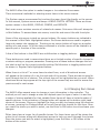
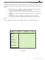
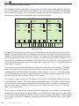
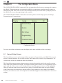
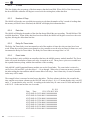
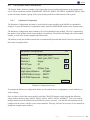
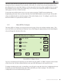
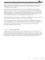
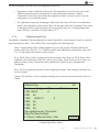
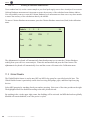
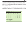
7.2 The Specific Display Screen
The Specific Screen displays an overview of the current chemical levels and feed
times for one pool or spa. When the AK600 is controlling more than one pool or spa,
a series of numbers will appear next to the screen title, System. These numbers correspond with a specific body of water. To view information on a specific pool or spa,
press the corresponding number in the screen heading.
3YSTEM
)4%- P( /20 -EAS
4EMP
0, 0(
3ET
/N4ODAY
88
&LOW
Specific Screen
The specific screen can display measurements from eight sensor inputs. The controller will display the name of each sensor input along with its current measurement, the
user specified set point, the time the corresponding feed devices have been on in the
last 24 hours, and whether the flow to the system is on or off. You may change the
order that the sensor displays this information in.
Each column on the specific screen serves a specific function. The AK600 is designed
so that the operator can find the current measurement for each sensor input quickly
and easily. The name of each sensor input being received is displayed under the ITEM
heading.
All current measurements are displayed under the Meas heading. The box next to the
current measurement is used to display whether the corresponding relay is currently
on or off. An X in this box indicates that the relay is currently on. An O in this box indicates that the feed relay has already been on for its maximum
allotted time. This is called an overfeed alarm. The controller will not allow this relay
to feed more chemicals in to the system until the overfeed timers are reset. An “a” to
the left of the relay status box indicates that an alarm condition for that relay exists.
The ON TOdAY heading displays the total time that the associated relay has been on
since the controller was reset. The AK600 factory default settings will reset the controller every 24 hours at 8:00 am. The controller can also be manually reset.
38
Pentair Water Commercial Pool and Aquatics™
12-15-07
AK600
The Flow column is used to indicate whether or not there is flow in the system. When
there is flow an X will appear in the box. The box will be empty if no flow is detected.
If the AK600 has any kind of alarm it will alert you here. The controller will display
the alarm condition, as well as the relay that has met or exceeded this condition.
More information about specific alarm codes may be found on p. .
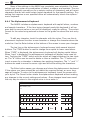
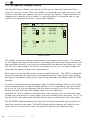
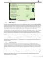
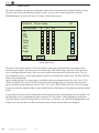
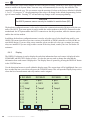
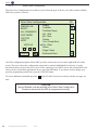
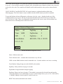
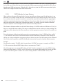
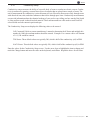
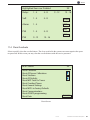
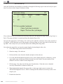
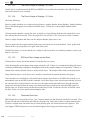
7.3 The data display Screen
The data display screen displays recorded data from selected sensors. The operator
has be ability to choose how often the controller will record its readings. The AK600
can record data at any interval in the range of two (2) seconds to eighteen (18)
hours. In the absence of power, the AK600 retains all recorded data and program values for up to ten (10) years.
-MDDHHMMP(/2000-4EMP XX
$$ $5 0$
05
data display Screen
The data display screen will show up to 10 lines of recorded readings at a time. The
controller will automatically display the 10 most recent recorded data lines. Each line
of data contains the time and date of the recording, and the sensor readings at the
time the record was made. Sensor data readings from modules 1-3 may be obtained
by touching the desired module one, two or three (1, 2, or 3), on the bottom right
hand portion of the screen.
12-15-07
Pentair Water Commercial Pool and Aquatics™
39
AK600
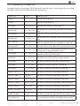
The status code of the flow, alarm, remote, modem, and password security level for all
three sets of sensors are recorded during each reading. To view these status code readings, usually referred to as the FARmP readings, use the right arrow button
while in the
data display screen. The status code reading is displayed under the first letter of the device
name.
•
F
•
A
•
R
•
M
•
P
•
B
•
W
o
the Flow status code,
Records whether the flow was on or off at the time of the reading.
1 = Flow
0 = No Flow
o
the Alarm status code,
Records whether or not any alarms were on at the time of
the reading.
1 = Alarm
0 = No Alarm
o
the RS232 status code,
Records whether an RS232 connection was in use since the
last reading.
1 = RS232 Connection in use
0 = RS232 Connection not in use
o
the modem status code,
Records whether or not the installed modem was in use
since the last reading.
1 = Modem in use
0 = Modem not in use
o
The user determined password level
Records the pre-determined password level of anyone using
the controller since the last reading.
o
The backlight Status
Records Whether or not the touch screen backlight was on
at the time of the reading.
B = Backlight on
= Backlight not on
o
Sensor Warning
Sensors may have been over calibrated or need to be re
placed
W = Sensor Warning
= no sensor warning
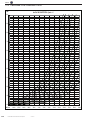
The AK600 has the ability to store 6505 lines of data, the equivalent of 271 days of hourly
recordings. To view more data measurement lines, you can scroll line by line using the
up and down arrow
buttons on the bottom of the screen. To scroll more
quickly through the data, the page down PD and page up PU buttons will move your view
up or down a page. A page in the data display screen is the equivalent of 10 lines of data.
To find data from a specific day, the day down DD button will take you to the first reading
of the previous date and day up DU buttons will move you to the first reading of the following date. To see additional information on the same line, use the left and right arrow
buttons.
40
Pentair Water Commercial Pool and Aquatics™
12-15-07
AK600
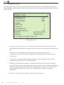
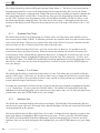
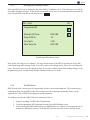
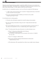
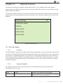
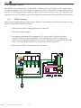
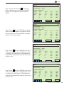
7.4 Program the Data Recording Interval
$ISPLAY
#ONFIG 3ERVICE
The factory default data recording
interval is one hour. To change the
data recording interval start in the
system screen. Open the CONFIg
menu by pressing on the heading
with your stylus
88
88
'ENERAL3ETUP
3YSTEM
!DV3ETUPS
0ROGRAMMING
#OMMUNICATIONS
'ENERAL3ETUP
Open the general Setup menu by
pressing on the menu title with your
'LOBAL!LARM
'LOBAL!LARM$ELAY /VERFEED#LEAR4IME
/VERFEED#LEAR4IME
0/WER/N$ELAY -ODULE.AME -ODULE.AME -ODULE.AME "ACKLIGHT4IME3ECONDS
$&,"ACKLIGHT
.ONE
$ATA3ETUP
#(!.'%
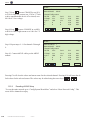
Open the data Setup menu by
pressing the data Setup button.
$ATA3ETUP
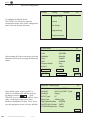
The data Setup menu will open with
the time spacing already highlighted.
Press the change button with your
stylus. The alpha numeric keyboard
will automatically open and prompt
you for a new data recording interval.
4IME3PACING 5SED .UMBEROF$AYS $ATA,INE 2,9/N4IMES)NDEX
%VENT)NDEX
3ENSORS
88
#(!.'%
12-15-07
Pentair Water Commercial Pool and Aquatics™
41
AK600
7.5
Summary Display Screen
The Summary Screen provides a brief overview of the sensor readings and relay status for all systems controlled by the AK600. For each system, the AK600 will display
the current ph reading, the current ORP reading, the current temperature, the feed
relay status, and the flow status for each individual system.
393
393
P( /20
P( /20
P( /20
4%-0
4%-0
4%-0
&&&
&&&
.%84
22
X
X
393 88
&&&
07$
Summary Screen
The AK600 will display the status of the feed relays controlling the chemicals to the
system. The feed relay status is displayed in a box to the right of the current sensor
reading. If the feed relay status box has an “O” inside, the relay assigned to this sensor is in overfeed and will not turn on again until the overfeed timer is cleared. An X
in the feed relay status box indicates that the relay is currently on. On occasion a letter “a” will appear to the right of the feed relay status box. This “a” indicates that the
feed relay is in alarm.
The summary screen also displays the flow switch status for each system. The flow
status is located on the bottom left hand side of the summary screen. The system
is identified by an F and then the number of the system, 1, 2, or 3. The box to the
right of the System number is used to display the status of that system. An “x” will
appear in this box when there is flow in the system.
The status for each of the first 12 relays in the AK600 is displayed along the bottom
of the summary screen. There are twelve individual boxes. The order of these boxes
is the same as the numbering scheme of the relays: relay one status is displayed in
the first box, relay 12 status in the last box, etc. When a relay is on an “X” will appear in its specific box.
The summary screen will be slightly different depending on the types of sensors and
devices you have installed on your AK600. If the AK600 has been set up to work with
an AK Color system with an AK615 or AK616 sensor module, the letter “c” will appear
to the right of the SYS 3 heading. For more information on the AK Color refer to Section 12.1.
42
Pentair Water Commercial Pool and Aquatics™
12-15-07
AK600
The summary screen also contains a brief overview of information that can help you
to maintain your water balance. The Water balance screen is reached by pressing the
NExT button at the bottom right hand corner of the summary screen.
393
393
39388
!LKALINITY (ARDNESS 4$300- #YANURIC ,ANGELIER,3)
0UCKORIUS03)
2YZNER23)
"
"
#
"
"
#
.A#L00- ""ALANCED
##ORROSIVE
33CALING
"
"
#
.%84
Water Balance Screen
The AK600 will calculate your waters score on several water balance indices based on
the sensor measurements and some values that must be entered by the operator. A
“C” will appear next to any index value that indicates your water is corrosive. A “B”
will appear next to any index value that indicates your water is balanced. An “S” will
appear next to any index value that indicates your water is scaling.
.%4 #( #( #( #( 37
XX
.%84
Summary / RS485 Screen
Touching NExT again will take you to the RS485 network screen. These screens allow
you to view
sensor values of any networked sensors. The AK600 can display information from five
networked sensors. The RS485 network screen is actually two screens combined in
to one display: the first five lines on the screen displays the sensor values, and the
NOTE
If no network items are installed, the NEXT button takes you
back to the summary screen.
12-15-07
Pentair Water Commercial Pool and Aquatics™
43
AK600
7.6
MPS Timers
The AK600 contains 16 physical relays and 8 soft relays. Physical relays are used to control the devices in
your pool room. Soft relays are used to expand the capabilities of the relays and can be used to program the
controller to react to the conditions created by the physical relays.
The relays in the AK600 are organized in to five distinct groups. The physical, or R relays are used to control physical devices attached to your controller. “R” relays are numbered 1 through 16. Soft relays, or S
relays are used to run operations where more than one device is involved. “S” relays are numbered 1-8.
Alarm or A relays are used to turn on an alarm condition when user specified conditions are met. “A” relays
are the alarm relays, numbered 1-4. Pager/Voice/Email relays, or PVE relays are used to tell the AK600 to
call a specific pager number and to send it a user specified numeric string of information. “P” relays are
numbered 1-8. V relays are the voice relays, numbered 1-16.
To view the status of a specific group of relays, use the appropriately lettered button at the bottom of the
MPS Timer Screen. The MPS timers for the relays in the AK600 are displayed in groups of four. The MPS
timers are grouped numerically by relay group when displayed. The first four R MPS timers will always be
displayed first. To view other timers, press the NEXT 4 button on the bottom right of the screen. This button
will scroll forward to the next group of four MPS timers. To scroll backwards, use the PREV 4 button on
the bottom left of the MPS Timers screen.
-03
4/4!,
2 $AY#OUNT 2 $AY#OUNT 2 $AY#OUNT 2 $AY#OUNT 2
02%6
3
/.4/$!9
!
/+
4)-%2XX
#NT
#NT
#NT
#NT
06%
.%84
MPS Timer Screen
Mini Programs are used to control all the relays in the AK600. These mini programs tell the controller
which relay to turn on, when to turn them on, how long they should stay on for, and how long to wait before
turning on again. They can also tell the controller to page or call a specific technician when a specific
condition occurs.
44
Pentair Water Commercial Pool and Aquatics™
12-15-07
AK600
The AK600 uses up to forty-four (44) Mini Programs (MPS) to determine which relays, alarms and pagers should be ON or OFF. Each relay in the AK600 can be operated with any one of the 44 mini programs.
Relays in the AK600 are configured at the factory to accept any of the mini programs and function with the
selected program. More information about selecting an MPS for each relay in use can be found in the
section on programming, located on p.
The MPS timers screen is often used when troubleshooting the programming of the AK600. This screen can
be used to determine how long each relay and its associated device have been on since the controller was
last reset, the total time the relay has been on for the current date, and the amount of time remaining until
the relay turns on or off again.
The TOTAL column in the MPS timers Screen displays the total time that each relay and the
associated device(s) have been on since the last controller resent.
The ON-Today column displays the amount of time that each realy has been on for the current date.
The TIMER column displays the amount of time left until the relay will turn on or off, depending on
its current state. The curent state of each relay is displayed in the box at the end of each row.
An empty box indicates that the relay is currently off and the timer is counting down until the relay
turns on again.
A box with an “X” in it indicates that the relay is currently on and the timer is counting the time until
the relay turns off.
This screen also displays the CNT or count, the number of times the relay has turned on since the
settings were last cleared.
12-15-07
Pentair Water Commercial Pool and Aquatics™
45
AK600
7.7
Information Screen
The Information Screen contains system information about the operation of your AK600. This screen provides information on how long the controller has been in operation, its serial number and the date of the last
software update.
!+$
XX
0OWER/N#YCLES
4OTAL(OURS/N 3ERIAL.UMBER &UTURE
-03$ELAY
2ELAYS/N
7ATCHDOG4IMER
#ONSTANT#HECKSUM &!5,43 ./3934%-&!5,43
-ODEL !+$$ATE
&GPM4OTKGAL4EMP&AR
Information Screen
1.
Power ON Cycles. A power cycle is a change in the power status, from on to off or off to on.
The AK600 counts and displays the number of times the power to the controller has been turned
ON.
2. Total Hours ON: The AK600 counts and displays the total number of hours that
it has been in operation. The hours of operation are not cleared if power to the controller is
cycled or lost.
46
3.
Serial Number: The unique number for this controller. Enter this number on the warranty
registration card and return to Acu-Trol immediately.
4.
MPS Delay: This displays the number of seconds the controller will wait before turning any
relay on. To ensure proper relay function, this number must be zero (0). During the initialization
and power up phases of operation, This delay is temporarily set at thirty (30) seconds to allow
sensor readings to adjust to the current water conditions before it attempts to make any
adjustments.
5.
Relays ON: This displays the number of relays that are currently on.
Pentair Water Commercial Pool and Aquatics™
12-15-07
AK600
7. Watchdog Timer. The AK600 has several built in programs that observe the functions of the
controller and ensure that the controller is functioning properly. The watchdog timer monitors
the AK600 for unexpected operations. If the AK600 has an error, the watchdog timer will reset
the system and clear the error. The Information screen displays how many times this watchdog
reset has occurred.
8.
Faults: System faults in the AK600 are rare: this line generally reads NO SYSTEM FAULTS.
If an internal system fault occurs, this line will display information about the fault. Each fault
has a specific failure code. The message indicates which fault is present. Controllers with a
system fault will generally not function properly. Contact your local Acu-Trol dealer for
assistance.
9.
Model: Displays the current software version in the controller, and the date that software was
released.
10. Fl=gpm, Tot=kgal, Temp=Far: This line indicates the units that the controller is currently
configured to display Flow Rate, Total Flow, and Temperature in. The AK600 can display this
information in standard or metric units. The controller must display all of these measurements in
the same measurement system. You will not be able to display some information in standard
units and other information in metric units.
12-15-07
Pentair Water Commercial Pool and Aquatics™
47
AK600
Chapter 8
The Configuration Menu
The CONFIGURATION MENU contains all of the sub-menus that allow the user to program and customize
the AK600. When programming or organizing the AK600 it is important to remember that all changes are
automatically saved. There is no way to reverse selections once they have been made. Cycling the power to
the AK600 will not reset the programming in the controller.
The CONFIGURATION MENU contains these sub-menu options: General Setup, System, Adv Setups,
Programming and Communication.
$ISPLAY
#ONFIG 3ERVICE
88
'ENERAL3ETUP
3YSTEM
!DV3ETUPS
0ROGRAMMING
#OMMUNICATIONS
Configuration Screen
To access each of these sub-menus, touch the display on the item would like to look at or change.
8.1
General Setup Screen
The General Setup screen is used to set up the basic parameters of operation for your AK600. This screen is
used to set alarm parameters, the overfeed reset time, and to name each system for easy identification. The
General Setup screen also contains the Data Setup Submenu.
The General Setup menu contains eight menu items, which are discussed in detail in the next few sections.
These menu items contain no sub-menus. To change the settings of these items, use the up and down arrows
on the right side of the screen to scroll through the menu items. The current menu item will be highlighted.
When you reach the menu item you want to select, press the CHANGE button with your stylus. Settings
in the General Setup screen need to be entered carefully. These settings are used in many of the AK600’s
functions, and an incorrect value will complicate the troubleshooting process and could result in an incorrect
reading.
48
Pentair Water Commercial Pool and Aquatics™
12-15-07
AK600
'ENERAL3ETUP
'LOBAL!LARM
'LOBAL!LARM$ELAY /VERFEED#LEAR4IME
/VERFEED#LEAR4IME
0/WER/N$ELAY -ODULE.AME -ODULE.AME -ODULE.AME "ACKLIGHT4IME3ECONDS
$&,"ACKLIGHT
.ONE
$ATA3ETUP
88
#(!.'%
General Setup Screen
8.1.1
Global Alarm %
The global alarm percentage is the most basic alarm condition in the AK600. The user sets the global alarm
percentage. The AK600 monitors the chemical measurements, and then compares them to the set point. The
global alarm percentage is used to calculate an acceptable operating range for the chemicals in the system.
The acceptable operating range is the global alarm % above and below the set point. If any of the chemical
measurements are outside of this acceptable operating range, the AK600 will activate the alarm.
The Global Alarm % is measured in percentage units. The factory default global alarm % is 10%. To change
the global alarm percentage, highlight the item using the up and down arrow buttons. Once highlighted,
press the CHANGE button. The alphanumeric keyboard will automatically appear and allow you to enter a
new global alarm percentage. Once you are done entering the new global alarm percentage, press the
ENTER button to save your changes.
The Specific display screen and the Summary display screen both display the letter "a" next to a sensor
measurement if the measurement is far away from the set point. This acceptable operating range is based on
the global alarm percentage. The letter “a” alarm indicator is always based on the alarm percentage, even if
it has been disabled.
8.1.2
Global Alarm Delay
Some fluctuation of the chemical levels is normal in every body of water. A reading outside of the
acceptable operating range may soon be corrected by the scheduled addition of chemicals to the water. To
allow the controller time to react to the situation as well as time for new chemicals to mix in to the system,
the AK600 will delay activating its alarm LED and any programmed pager routines for a specific period of
time.
The Global Alarm Delay is measured in seconds. The factory default global alarm delay is ten (10) minutes.
To change this value, use the up and down arrow buttons to highlight the global alarm delay menu item. To
select, press the CHANGE button. The AK600 will automatically launch the alphanumeric keyboard and
prompt you to enter the new value. Once you are done entering the new global alarm delay, press the
ENTER button to save your changes.
12-15-07
Pentair Water Commercial Pool and Aquatics™
49
AK600
The Global Alarm Delay behaves differently from the Global Alarm %. This delay is only used when the
Programming/Alarm/Wiz is reset. In the programming for the alarm the delay that is used is the Global
Alarm Delay. If the delay is changed in the Config/General menu there is nothing else that has changed and
the original alarm delay is still in effect. To use the new delay go to the Programming/Alarms and either
use the “WIZ” button to reset all parameters for the selected alarm to defaults with the new delay, or edit
the Alarm and manually change the delay. The delay has no effect on the ‘a’ that appears next to the measurement in the display screens. Whenever the measurement is out of the range of the Alarm % the ‘a’ will
appear.
8.1.3
Overfeed Clear Times
The AK600 bases much of its programming on a 24 hour clock. All of the timers in the AK600 are set to
meet certain criteria within 24 hours. To maintain operations, the controller must clear and reset these timers
every twenty four hours. There are two overfeed clear times in the AK600. To have the controller clear the
timers just once per day, set both Overfeed clear times to the same time.
The factory default Overfeed Clear Time 1 and 2 are set for 8:00 a.m. However, it is possible to set the
overfeed clear time to any hour of the day. When the current time matches the Overfeed Clear time, the
overfeed timers will be cleared and any appropriate data saved. To change the overfeed clear time, use the
up and down arrow buttons to highlight the appropriate Overfeed Clear Time menu item. To select, press
the CHANGE button. The AK600 will automatically launch the alphanumeric keyboard and prompt you to
enter the new value. Once you are done entering the new overfeed clear time, press the ENTER button to
save your changes.
8.1.4
Module 1, 2, or 3 Name
The AK600 has the ability to control up to three bodies of water. This means that your AK600 will be displaying 3 ORP values, 3 pH values, etc. In order to make it easy to assign measurements to a specific body
of water, it is possible to give each body of water a name, instead of relying on memory to identify which
system number belongs to which body of water.
To change the system name of a body of water, use the up and down arrow buttons to highlight the Module
1, 2, or 3 menu items. To select, press the CHANGE button. The AK600 will automatically launch the
alphanumeric keyboard and prompt you to enter the new system name. Once you are done entering the new
system names, press the ENTER button to save your changes.
8.1.5
Backlight Time
The AK600 has a backlight built in to the touch screen display. The backlight will automatically light any
time the touch screen is pressed. The length of time that the backlight is on after the screen has been touched
can be programmed by the operator.
The factory default value for Back Light Time is 30 seconds. To change the back light time, use the up and
down arrow buttons to highlight the Back Light Time menu items. To select, press the CHANGE button.
The AK600 will automatically launch the alphanumeric keyboard and prompt you to enter the new back
light time. Once you are done entering the new backlight time, press the ENTER button to save your changes.
50
Pentair Water Commercial Pool and Aquatics™
12-15-07
AK600
8.1.6
DFL1 Backlight
The AK600 is configured to allow a user to turn on the AK600 backlight with an external switch instead of
the touch screen. The external switch can be wired in to the controller using the DFL1 slot in any one of the
three systems (or modules) installed in the AK600. In order for the external switch to work properly, you
will need to tell the AK600 in which slot you have installed the switch.
To select the switch slot for the DFL1 backlight, use the up and down arrow buttons to highlight the Back
Light Time menu items. To select the module that the switch has been wired to, press the CHANGE button.
This will toggle the selection between the three available modules and none (no external switch installed).
When you reach the appropriate module, exit the screen.
8.2
Data Setup
The AK600 has the ability to store 6505 lines of data, the equivalent of 271 days of hourly recordings. These
readings can be viewed in the Data Display Screen. (For more information please see p. 37) The DATA
SETUP button located in lower left corner of General Setup screen is used to access the Data Setup Menu.
This menu allows the operator to view information about the data records, and to set the time interval for
data recording. The Data Setup menu also contains the SENSORS button, which opens the Sensor Setup
sub-menu.
$ATA3ETUP
4IME3PACING 5SED .UMBEROF$AYS $ATA,INE 2,9/N4IMES)NDEX
%VENT)NDEX
3ENSORS
88
#(!.'%
Data Setup Screen
8.2.1
Time Spacing
The time spacing in the Data Setup menu is the Amount of time between recordings. The time between
recordings in the AK600 can range from two second intervals to eighteen hour intervals. The factory default
setting has the AK600 record the sensor readings once per hour. The time spacing is the only value in this
screen which can be changed. All the other menu items are information to help the operator manage the data
memory.
12-15-07
Pentair Water Commercial Pool and Aquatics™
51
AK600
8.2.2
% Used
This line displays the percentage of the data memory that has been filled. When 100% of the data memory
has been filled the controller will begin to record over the existing data, oldest data first.
8.2.3
Number of Days
The AK600 will use the user specified time spacing to calculate the number of day’s worth of readings that
the memory will hold. Once calculated, the AK600 will display this information here.
8.2.4
Data Line
The AK600 will display the number of the data line that will hold the next recording. The AK600 has 6700
available data lines. When all the data lines have been filled, the AK600 will begin to record over the existing data, deleting the oldest data line first.
8.2.5
Relay On Times Index
The Relay On Times Index is an incremental record of the number of times the relay on times have been
saved. When the overfeed timers reset themselves, the controller saves the relay on times for future use, and
increments the Relay On Times Index. The Relay On Times Index can range from 1 to 365.
8.2.6
Event Index
The Event Index is only available on controllers that have the AK600 memory module installed. The Event
index will record the number of times each relay is turned on or off. These power cycles are recorded in to
the expanded memory along with the date and time of the recording.
Only AK600’s with Expansion Memory module can use the Event Index. The event index is a timed record of every ON and OFF cycle that relays 1 – 16 go through. When relay #1 turns on an entry is made in
the index noting the time and date and the current state of all relays. Later when relay #1 turns off another
index entry will be made.
The example below is an actual section from a data index. The first column is the date, the second is the
time, and the next sixteen columns are the ON/OFF state of relays 1-16, A “0” means that the relay was OFF
and a “1” means that the relay was ON. According to the index relay #4 came on at 09:34:48 and turned off
at 09:34:52. So the total on time was 4 seconds.
111 1111
Date
Time
1234 5678 9012 3456
05/07/6002 09:34:52 0000 1100 0000 0000
05/07/6002 09:34:48 0001 1100 0000 0000
05/07/6002 09:32:28 0000 1100 0000 0000
05/07/6002 09:32:24 0001 1100 0000 0000
05/07/6002 09:32:20 0000 1100 0000 0000
05/07/6002 09:31:00 0001 1100 0000 0000
05/07/6002 09:30:34 0000 1100 0000 0000
05/07/6002 09:28:44 0001 1100 0000 0000
52
Pentair Water Commercial Pool and Aquatics™
12-15-07
AK600
To see how many index entries you have you can press the DATA SETUP button located in the lower left
corner of General Setup window. The Event Index is the number of records currently stored. The maximum
number of records that can be stored is 4,500. When all 4,500 records have been used the oldest recorded
entries will start to be over written. On a very active controller the last 7 – 10 days will be indexed. The
amount of days recorded depends on how often relays or going on and off.
8.2.6.1
Graphing the Event Index
The most powerful usage of the event index comes when you graph is against the sensor data index. This
can be done with the AcuGraph software package. When you graph events against sensor data you can
actually see trends and control in action. In the below graphs you can see two sanitizer relays label Chlor
(Chlorinator) and B/U (Backup) come on when ORP1 level drops.
12-15-07
Pentair Water Commercial Pool and Aquatics™
53
AK600
8.2.7
Sensor Setup
The AK600 will allow the operator to determine which sensor measurements are displayed when viewing
the data in the System and Summary Display Screens. To access the Sensor Setup menu, touch the
SENSORS button, located in the lower left corner of Data Setup screen.
-/$5,% 3ENSOR3ETUP
88
-EASUREMENT - - -
0(
/20
004EMP
#OND
#OND
0LOW
0HIGH
4OGGLE
4OGGLE
#(!.'%
Sensor Setup menu
The Sensor Setup menu contains a list of all possible sensors that could possibly be measured by each
installed sensor module. The main sensor list contains pH, ORP, PPM, Temp, Cond, Flo1, Plow (Pressure
Low), and Phigh (Pressure High). There are more possible sensors than are listed in this screen. To view
these additional choices, use the toggle buttons on the lower left hand side of the screen. The first TOGGLE
button will scroll through
choices on the fifth line; the sensor choices available in this second menu include Flo1, Flo2, Tot1, TOT2,
CPPM, and TPPM. The second TOGGLE button will scroll through choices on the sixth line; the sensor
choices available in this third menu are Flo1, Flo2, Tot1, Tot2, CPPM, TPPM, and Cond. An X will appear
in each box under the Module header to show which measured functions are being displayed for that module
board.
It is possible to select the sensor readings that will be displayed when viewing the data for each module. Use
the directional arrows to highlight the sensor checkbox for each module. Once highlighted, touching the
CHANGE button in the lower right hand of screen selects, or unselects, the sensor box highlighted for each
module. The selections have no effect on the data being recorded, only the data to be displayed.
54
Pentair Water Commercial Pool and Aquatics™
12-15-07
AK600
8.3
The System Menu
The System menu is one of the most important menus in the AK600. This menu is the gateway to all the
menus and settings for the controller system itself, the hardware, the security settings, and the sensor module
assignments. The System menu is a very large submenu and contains multiple sub-menus, as well as
important system settings. The following sections will explain each of these submenus in detail.
3YSTEM-ENU
4IME $ATE 7EEKDAY 5NITS
(/! 0ROGRAM-ODE
3ERIAL
-ONDAY
%NGLISH
%NABLED
%ASY
88
(!2$7!2%
$)30,!9
02).4
3%#52)49
2ESET-ENU
#(!.'%
System Menu
One of your first steps to set up an AK600 will be to set the Time, Date, Weekday, Units, and Mode. These
are set at the factory, but may need to be entered or changed. The time, date, day, and units are critical
components to most of the programs that will be run by the AK600. In order for the controller to function
correctly, these values must be correct. These settings are important for calculating correct readings and
troubleshooting.
8.3.1
Time
The current time of day is displayed here. The AK600 uses a 24 hour clock. Times will range from 00:00:00
(12:00 a.m.) to 23:59:59 (11:59 p.m.)
To change the current time, Use the directional arrows to highlight the settings. Then press the CHANGE
button to select the item. The alphanumeric keyboard will automatically launch and prompt you to enter a
value. Once the value has been entered, press the ENTER button to save your changes.
8.3.2
Date
The current date is displayed here. The date can be displayed in either metric or English units. If metric is
selected the date is entered as dd/mm/yr, for English units the date is entered as mm/dd/yr.
To change the current date, use the directional arrows to highlight the settings. Then press the CHANGE
button to select the item. The alphanumeric keyboard will automatically launch and prompt you to enter a
value. Once the value has been entered, press the ENTER button to save your changes.
12-15-07
Pentair Water Commercial Pool and Aquatics™
55
AK600
8.3.3
Weekday
The current day of the week is displayed here. To change the current day of the week, use the directional
arrows to highlight the settings. Use the change button to scroll through the selections, which includes
Monday through Sunday. Once you have reached the appropriate day, exit the selected item using the up and
down arrow buttons.
8.3.4
Units
The AK600 can display measurements in Metric or English units. To select one of these measurement systems, use the directional arrows to highlight the settings. Use the change button to toggle between the two
measurement systems.
8.3.5
Program Mode
(Version D6 and Higher)
The AK600 will allow the user to select between Easy and Advanced programming modes. When set to
Advanced the ability to change and add commands as well as the sequencing capability of the AK600 are
enabled. When in easy programming mode only the values of a command can be changed.
CAUTION
When editing an MPS, if sequences other than 1 are used the MPS will
default to advanced programming. If an MPS is contained in advanced
programming, its associated values can be edited at any time in easy
programming, so long as only sequence 1 is used.
8.3.5
HOA
The AK600 can operate solely on the programming provided by the operator. However, it can also be
configured to allow the operator to change easily between manual operation, having certain relays off
altogether, and allowing the programming to manage the controller. This configuration is called HOA mode.
When HOA mode is enabled, a button in the MPS screen will allow the user to easily turn relays off and
on manually, turn individual relays off completely, and to allow the controller programming to operate the
relay.
To select one of these measurement systems, use the directional arrows to highlight the settings. Use the
change button to toggle between the two measurement systems. For more information on working with
relays with HOA enabled, please see p.80.
8.3.6
Serial Number
The serial number can be viewed here. The serial number is a unique identification number for your AK600.
It can not be changed.
56
Pentair Water Commercial Pool and Aquatics™
12-15-07
AK600
8.4
The System Menu Sub Menus
The System Menu contains a number of sub-menus that are accessed through buttons on the system menu
screen. These sub-menus include: HARDWARE, DISPLAY, PRINT, SECURITY, and RESET MENU: Each
system sub-menu contains a group of like items, dealing with the overall function of the system.
8.4.1
Hardware Configuration
The Hardware Configuration sub-menu is used when the sensor modules in the AK600 are expanded or
changed. To open the Hardware Configuration menu, touch the HARDWARE button, in the System menu.
The Hardware Configuration menu contains a list of each installed sensor module. This list is organized by
the number of the module slot the sensor module is installed in. The AK600 will display the sensor module
number, as well as the sensors supported by that module.
The modem, serial port and the external ram are automatically detected and selected, not user selected, and
their status is displayed here.
(ARDWARE#ONFIGURATION
88
-ODULE !+P(/204
-ODULE !+P(/204#OND
-ODULE %MPTY
234YPE
0#
2ELAY4YPE 2ELAY4YPE
(IGH3PEED-ODEM -4
5!24230RINTER %-049
+2!-%XPANSION %MPTY
#(!.'%
Hardware Configuration Screen
To navigate the Hardware Configuration Menu, use directional arrows to highlight the sensor module you
wish to change.
Once you have selected the sensor module, touch the CHANGE button to toggle through the following
sensor module options: Empty, AK610, AK612, AK614, AK615, AK616, and AK617. The correct sensor
module numbers must be selected for the AK600 to measure correctly. Your AK600 will automatically be
configured at the factory with the correct sensor modules. This step will only be necessary if you uninstall or
change the original sensor modules.
12-15-07
Pentair Water Commercial Pool and Aquatics™
57
AK600
After selecting the correct sensor module for each of the three modules, touch the x in the upper right hand
corner to return to the System Menu. Your new entry will automatically be saved by the controller. The
controller will then ask you; “Do you want to reset the associated 4 relays to the factory defaults for Module
1, 2 or 3?” If you press “Y” the programming of the relays will change to the default programming for that
type of sensor module. Pressing "N" will not make any changes to the current programming.
CAUTION
The AK612 pressure sensor can only be installed in module three (M3).
The hardware configuration menu is also used to selecte the communication method being used by the controller. The RS232 Type menu option is used to enable the wirless modem or the RS232 connection on the
motherboard. the PC option enables the RS232 connection or the dial pu modem, while the internet option
enables the wireless modem.
In addition, the hardware configuration menu is used to select the type of relay board being used by your
AK600. This menu item allows previous versions of the AK600 or AK200 controller to work with the current AK600 design. If you are using a new controller, please set this to 8 relay type, no matter how many
relays are installed. If you are using an older version of the rleay board, contact your Acu-Trol dealer for
assistance.
8.4.2
Display
The DISPLAY submenu is used to display the order that information from each sensor is displayed in the
SUMMARY and SPECIFIC display screens. It is also the gateway used to change the order that the
information from each sensor is displayed in. The Display menu is opened by pressing the DISPLAY button
in the SYSTEM menu.
Use the directional arrows to scroll within the display menu. The current item will be highlighted. Once you
have reached the item you wish to edit, press the CHANGE button. This will open the Display Setup screen,
where the list of measurements and relay number can be assigned.
2,9-%!3
2,9-%!3 2,9-%!3 88
P( /20 4EMP
P(
/20
4EMP
P(
/20
4EMP
#(!.'%
Display Screen
58
Pentair Water Commercial Pool and Aquatics™
12-15-07
AK600
8.4.2.1
Display Setup
The Display Setup screen opens the list of measurements that can be displayed. This screen will enable you
to select which measurement will be displayed on a specific line. It also will enable the user to select the
relay that will be controlling that measurement. When you install a new sensor card in the controller, the
factory default settings for that card will be automatically updated and displayed here.
Navigate the screen by using directional arrows to move the arrow to the desired measurement or
condition for each line. It is also possible to select a specific relay to associate with a specific
measurement by touching the relay number to the left and then entering the measurement you wish to
associate with that relay. The process needs to be repeated for each relay and measurement
$ISPLAY3ETUP
2ELAY
88
P(
#OND
00-
4EMP
/RP
P(
COND
00-
4EMP
/20
P(
Display Setup Menu
The Display Setup menu contains all of the available sensors. An overview of each of these measurements,
and their requirements are listed below.
•
Cond1, 2, 3: Conductivity measurements monitor the mineral content of the water. These
measurements range from 0 to 9999 uS. When using conductivity sensors the TDS and NACL
concentrations can also be calculated by the AK600, described in the Calibrating
Conductivity section. The AK600 can monitor up to three conductivity sensors. Enabling
conductivity on an AK600 requires an AK613 or AK614 sensor module.
•
Fl1, 2, 3, 4, 5, 6: Digital flow inputs monitor the rate of flow of the water in the system. These
inputs should be connected to digital flow meters only. The output is displayed in gallons per
minute (gpm) or liters per minute (lpm) depending on the units selected by the operator. A
specific sensor module is not required to monitor digital flow meters. Digital flow meters do not
have a default configuration, and will need to be configured manually.
12-15-07
Pentair Water Commercial Pool and Aquatics™
59
AK600
•
Lan1, 2, 3: The Langlier saturation index is an indication of the waters tendency to be scaling,
corrosive or balanced. The controller will use current measurements along with the alkalinity,
Total dissolved solids (TDS) and hardness input by the operator. If a conductivity sensor is in use
the TDS used in the calculation will be the measured TDS from the sensor.
•
ORP1, 2, 3: ORP is the oxidation reduction potential measurement of the water. This
measurement is used to control the sanitizer and in the calculation of the displayed PPM
measurement.
• Temp1, 2, 3: The temperature inputs require the AK10K negative coefficient thermistor.
•
P1H, P2H: Pressure High is used to identify the high pressure input for the differential
pressure sensor. An AK612 pressure card is required to read both high and low pressures.
•
P1L, P2L: Pressure, low is used to identify the low pressure input for the differential
pressure sensor. An AK612 pressure card is required to read both high and low pressures.
•
PPM1, 2, 3: The AK600 can use the AK610 sensor card to display a calculated PPM reading.
The AK600 can also measure Colormetric PPM using the AK615 and AK616 sensor modules and
an AKColor.
•
pH 1, 2, 3: The pH of the water in your system is very important for pool maintenance.
The AK600 will monitor the pH of your water using any of the available sensor modules. The pH
input uses temperature compensation for increased accuracy.
• TPPM 1, 2, 3: There are two types of chlorine in your system: free chlorine which is available for
sanitization, and combined chlorine, which has combined with other molecules in the water and
is no longer able to sanitize. The total chlorine measurement will tell you how much total
chlorine you have in your system using an AKCOLOR TOTAL and an AK615 or AK616 sensor
module.
•
60
CPPM 1, 2, 3: There are two types of chlorine in your system: free chlorine which is available for
sanitization, and combined chlorine, which has combined with other molecules in the water and is
no longer able to sanitize. The combined chlorine measurement will tell you how much
unavailable chlorine you have in your system using an AKCOLOR TOTAL and an AK615 or
AK616 sensor module. Combined chlorine measurement from an AKCOLOR TOTAL.
Pentair Water Commercial Pool and Aquatics™
12-15-07
AK600
8.4.3
Printer Setup
To open the Printer Setup screen, touch the PRINT button, in the System Menu. The Printer Setup screen
contains the controls for the Communication module that will allow you to print your stored data from the
AK600 with a serial printer.
There are two methods of communicating with serial printers. One uses an RS232 cable to connect directly
to the motherboard of the AK600. The other method uses the serial connections on the communication board
to connect a serial printer directly to the AK600. Both methods expand the ability of AK600 to allow the
operator to print data lines, the controller setup, and the saved data.
0RINTER3ETUP
88
-OTERHBOARD23 0#
0RINTTIME)NTERVAL
0RINTER4YPE
7IDE
)F-ODEM"OARD)NSTALLED
0RINTERASSIGNEDTOTHE-ODEM23
#HANGINGTHE-OTEHRBOARD23
DISABLESCOMMUNICATIONSWITHTHE0#
3END3ETUPTO0RINTER
#(!.'%
3END$ATATO0RINTER
Printer Setup Screen
RS232 method: The first method uses the RS232 connector on the motherboard. An RS232 cable is used to
connect directly to a printer. When the RS232 connection is used for a printer, it disables the ability to communicate with a PC using the motherboard RS232 connector. The Motherboard RS232 setting on the Printer
Setup Screen controls the port setup for the RS232 connection. Pressing the CHANGE button will allow
you to switch between printer and PC connunication.
The second method uses the serial connections on the communication board, which adds an additional serial
port, dedicated for serial printers. Once the printer communication board (AK633) is installed, two additional buttons will appear on the Printer setup screen. This method allows data to be manually sent to the
printer.
To prepare to print, press the Send Setup to Printer: This will send the setup file to the printer. To print, press
the Send Data to Printer button to send the data file to the printer. The printing can be aborted at any time by
touching the top line when printing.
12-15-07
Pentair Water Commercial Pool and Aquatics™
61
AK600
8.4.4
Security
One of the most important features of the AK600 is the multiple levels of password security that are available for your use. To access the Main Security Setup Screen, press the SECURITY button, located in the
System Menu. This screen is used to set passwords, and enable and manage different security levels. Your
AK600 will be shipped to you without any security passwords.
-AIN3ECURITY3ETUP
-ASTER
/PERATOR /PERATOR /PERATOR 3ERVICE
3ERVICE
3ERVICE
#,%!2!,, 88
SELECT
#(!.'%
Security Screen
The security system in the AK600 has four (4) security levels. Each security level will have its own password. Each security level allows a different level of access. The AK600 will allow you to set one master
password, three passwords at the operator access level, and three passwords at the service access level. A
password protected controller will allow any user to view the display menu screen without entering a password. It is strongly suggested that you assign each technician or operator their own password. This will
allow you to monitor when the controller is viewed or modified, and by whom.
SERVICE: A service level password will provide the most limited access to the AK600. A password at this
level will allow the user to access the standard functions used to service the AK600 and the
body of water. A service password will allow the holder to view the current readings, as well as
calibrate or manually turn on relays; any changes in the programming are blocked. There are
three passwords at this security level.
OPERATOR: An operator level password allows viewing and modification of most of the settings in the
AK600. The operator security level will allow the user to access all areas of the controller, with
the exception of the security setup menus. An individual with operator level access will be able
to service the controller, as well as make changes to the programming and calibration data stored
by the AK600. There are three (3) passwords at this security level.
62
Pentair Water Commercial Pool and Aquatics™
12-15-07
AK600
MASTER: The master password allows the highest level of security clearance. The master password will
allow the user to access and modify every screen and command in the AK600, including the
creation and management of passwords. A master password must be entered in to the controller
before any other levels of passwords are created. Operator and service level passwords will not
be able to be assigned if there is no master password. There is only one master password per
controller. On any AK600 with password protection, the security level of the password
currently in use will be displayed in the upper right corner of the Main Menu screen. The
AK600 will record the security level and the password in use in the data log, along with the
current measurements and relay conditions. This information will tell the supervisor who
accessed the controller and at what time.
Security Level Summary
LEVEL
MASTER
OPERATOR
OPERATOR
OPERATOR
SERVICE
SERVICE
SERVICE
#
1
2
3
4
5
6
7
Description
Access to all screens including Security.
Access to all screens except Security.
Access to all items in the Display and Service menu
only except for global disable.
To enable the advanced menu with the voice modem a password is required. When the password is entered
it must match the first four numbers of one of the passwords in the security menu. In addition, only numbers
are allowed. A valid password would be “1234abcd”, then to access the advanced menu press 1,2,3,4 on the
touch tones on the phone. Invalid passwords include: “123”, 12a34, and 1two.
The AK600 also provides an additional layer of security by allowing an on site operator to activate a
communication lockout. This will prevent anyone from viewing or modifying the controller and its
programming with a modem or other communication device.
To activate the communication lockout mode you will need to make some adjustments to the Sync Bytes in
your AK600 and your AcuCOM software package. Sync Bytes provide a secondary form of security. The
AK600 and the AcuCOM software package both contain Sync Bytes. To communicate with a controller the
sync bytes in the communication software and the sync bytes in the controller must match. Every controller
with a modem is shipped with a corresponding version of AcuCOM software. If you wish to limit access to
your AK600 so that only a few individuals or computers can communicate with it; you will need to change
the sync byte values in the AK600 and in the AcuCOM software. For assistance with this, please contact
your local
12-15-07
Pentair Water Commercial Pool and Aquatics™
63
AK600
NOTE
When a password has been entered to allow access, it will be reset
when the backlight turns off.
NOTE
The password can use upper and lower case characters in addition to
numbers and symbols.
NOTE
When the wireless modem is being used any password
must be entered and security must be enabled or direct
communication "WILL NOT BE ALLOWED." This is one of the main
security features of the wireless.
8.4.4.1
Entering a Password
Selecting a password and using the multiple security levels available in the AK600 will help you to protect
your system, your patrons and your investment. Multiple security level passwords should be selected as
soon as the controller is installed.
-AIN3ECURITY3ETUP
-ASTER
/PERATOR /PERATOR /PERATOR 3ERVICE
3ERVICE
3ERVICE
#,%!2!,, 88
SELECT
#(!.'%
Security Screen
64
Pentair Water Commercial Pool and Aquatics™
12-15-07
AK600
To enter a password, use the directional arrows to highlight the desired level and touch the CHANGE button with your stylus. The alpha numeric keyboard will automatically open. Each password may be up to
ten (10) characters. You may use any combination of the characters available in the AK600’s alphanumeric
keyboard. Once you have selected your password, touch the OK button to save your password and close the
alphanumeric keyboard.
To clear all of the passwords, use the directional arrows to highlight the CLEAR ALL command. Press the
CHANGE button with your stylus to clear the current passwords. If you forget the Master pasword, you
will need to contact your dealer for assistance.
8.4.5
Reset Menu
The AK600 saves the factory default programming in its memory. As you are using and programming your
controller, you may want or need to reactivate these factory default settings. The Reset Menu will enable the
operator to restore some or all of these factory default settings. The Reset Menu also allows the operator to
clear alterations made by the operator to the function of the controller, such as clearing any sensor
calibrations or resetting the hardware configuration.
The Reset Menu is one of the many sub-menus of the SYSTEM menu. To access the Reset Menu, use your
stylus to press the RESET MENU button in the SYSTEM menu screen.
2%3%4-%.5
88
2ESET#ONTROLLER
2ESET!LL3ENSOR#ALIBRATIONS
2ESET4OTALIZERS
2ESET!LL$EFAULTS
2ESET-034OTAL/N4IMERS
2ESET/VERFEED4IMERS
2ESET'ENERAL3ETTINGS
2ESET-03STO&ACTORY$EFAULTS
2ESET#OMMUNICATIONS
2ESET!LL-03PROGRAMMING
2ESET$ATA
#(!.'%
The RESET MENU contains multiple menu items. Each menu item allows the user to reactivate some or all
of the factory default settings for the AK600.
•
Reset Controller: This command has the same affect as turning the AK600 OFF and ON without
actually cycling power.
•
Reset All Sensor Calibrations: This command clears all sensor calibrations, with the exception of
any installed flow meters. Once these calibrations have been cleared, each individual sensor will
need to be re-calibrated in the calibration screen.
12-15-07
Pentair Water Commercial Pool and Aquatics™
65
AK600
•
Reset Totalizers: This command clears the accumulated volume measurements for all flow
meters.
•
Reset Configuration: This command clears the hardware sensor modules and leaves the
programming intact. It is highly recommended that you do not use this setting without assistance
from your dealer.
•
Reset MPS Total ON Timers: Clears the cumulative MPS relay timers for all relays. Clearing
these timers will allow you to monitor how long any one relay is on over a certain period of time.
Total On Timers are not reset when the overfeed timers clear.
•
Reset Overfeed Timers: Clears the daily MPS timers for all relays. This command is especially
useful when you have reached your feed time limit and your AK600 is in overfeed on one or
more relays.
•
Reset General Settings: This command sets the general settings to the factory defaults. The
general settings on the AK600 include the alarm parameters, the sensor set-up, and the
organization of the data log.
•
Reset MPS to Factory Default: This action sets all relay configurations (MPS) to the factory
default settings and deletes all previous programming. It is important to specify the Hardware
Set-up from the System screen before performing this reset.
•
Reset Communications: This command resets the user programmed communication options to
factory default settings.
•
Reset All MPS Programming: This command clears all relay (MPS) programming.
•
Reset Data: Clears all Normal data, Event Data, and Relay On Time records
2%3%4-%.5
2ESET#ONTROLLER
2ESET!LL3ENSOR#ALIBRATIONS
2ESET4OTALIZERS
2ESET!LL$EFAULTS
2ESET-034OTAL/N4IMERS
2ESET/VERFEED4IMERS
2ESET'ENERAL3ETTINGS
2ESET-03STO&ACTORY$EFAULTS
2ESET#OMMUNICATIONS
2ESET!LL-03PROGRAMMING
2ESET$ATA
66
Pentair Water Commercial Pool and Aquatics™
12-15-07
88
#(!.'%
AK600
To activate one of the reset commands, Use the directional arrows to highlight the appropriate command for
the items you wish to reset and touch the CHANGE button. The controller will ask “Are you sure: Y or N”.
Press the Y button to reset the selected settings. Press the N button if you do not wish to reset the selected
settings at this time. Once you have confirmed your choice, The Reset Menu will stay open for any more
changes you wish to make.
Touching the “–more-” command at the top of the screen will open a second reset menu with the following
options.
2%3%4-%.5
MORE
88
2ESET.ORMAL$ATA
2ESET2ELAY/.4IME$ATA
2ESET%VENT$ATA
2ESET!,,(/!
2ESET.ETWORK#ONFIG
2ESET6OICE0AGER.UMBERS
2ESET#ALIBRATION&LOW
2ESET!LL6ARIABLES
2ESET$AY#OUNTERS
#LEAR!LL$AY#OUNTERS
#(!.'%
(more) Reset Menu Screen
•
Reset Normal Data: This command clears just the normal data records in the data log.
•
Reset Relay ON Time Data: This command clears the cumulative timers for only the
Relay ON Time.
•
Reset Event Data: This command clears just the event data records from the data log.
•
Reset All HOA: This command Sets HOA setting to “Automatic on ALL relays when the HOA
function has been turned on.
•
Reset Network Config: This command clears all of the user programmed
RS485 Network settings.
•
Reset Voice/Pager Numbers: Clears all Pager, Voice, and Email entries.
•
Reset Calibration Flow: Resets all Flow calibrations to defaults.
•
Reset All Variables: Resets the AK600 to the factory deefault settings.
•
Reset Day Counters: Not Used
•
Clear All Day Counters: Not Used.
12-15-07
Pentair Water Commercial Pool and Aquatics™
67
AK600
Chapter 9
Programming
The AK600 has an easy programming interface which allows the operator to modify the timing, set points,
and other operating parameters and variables that are a part of the standard factory programs or wizards.
These wizards have been optimized to work with your AK600. Mini Programs are used to control all the
relays in the AK600. These mini programs tell the controller which relay to turn on, when to turn them on,
how long they should stay on for, and how long to wait before turning on again. They can also tell the controller to page or call a specific technician when a specific condition occurs.
To enable these programs to work on any system and with any device, any relay or MPS in the AK 600 can
be programmed using a wizard and then modified to suit the system being controlled. The AK600 uses up
to forty-four (44) Mini Programs (MPS) to determine which relays, alarms and pagers should be ON or
OFF. Each relay in the AK600 can be operated with any one of the 44 mini programs. Relays in the AK600
are configured at the factory to accept any of the mini programs and function with the selected program.
In rare cases one of the many available wizards will not meet the needs of your application. In these
situations a custom program may be able to be written for your specific application. Please feel free to
contact your local Acu-Trol dealer or our factory technicians for assistance.
9.1
MPS Modules
Programming your AK600 to operate one or multiple devices is done in the Select MPS module screen. The
AK600 contains 16 physical relays and 8 soft relays. Physical relays are used to control the devices in your
pool room. Soft relays are used to expand the programming of the 16 physical relays.
3ELECT-03-ODULE
68
2ELAYS
3OFT !LARMS
06% Pentair Water Commercial Pool and Aquatics™
12-15-07
88
AK600
The relays in the AK600 are organized in to five distinct groups. The physical, or R relays are used to control physical devices attached to your controller. Soft relays, or S relays are used to run operations where
more than one device is involved. Alarm or A relays are used to turn on an alarm condition when user specified conditions are met. Pager/Voice/Email relays, or PVE relays are used by the AK600 to communicate
with a pager, voice line, or email account.
To open the Select MPS module screen, use your stylus to open the CONFIG menu and then the
Programming sub-menu. Once you have done this, the Select MPS Module screen will open. All the MPS
relays are numbered and are viewed in groups of four on the display screen. To configure a specific relay,
touch the number of its group directly on the screen.
9.1.1
Select MPS to Configure
The Select MPS to Configure screen opens the specific group of four relay modules and their status. This
screen will allow you to perform two functions: access and change the programming wizard controlling the
relay and change the function of the relay.
3ELECT-03-ODULETO#ONFIGURE 2,9
P(!CID -
7):
2,9
3ANITIZER -
7):
2,9
%MPTY
2,9
4EMP
02%6
7):
/+
88
-
7):
.%84
Select MPS to Configure Screen
You may scroll through all of the Relays in the AK600 using the NEXT 4 or PREV 4 buttons on the bottom
of the screen. Once you have finished in this screen, press the OK button to exit from this screen.
To change which device the relay is controlling, you will need to open the Select New Configuration Screen.
To do this, press the WIZ button on the same line as the MPS you wish to configure. The Select New
Configuration screen will automatically be opened.
12-15-07
Pentair Water Commercial Pool and Aquatics™
69
AK600
9.1.2
Select New Configuration
The Select New Configuration screen allows you to select the type of device you wish to control with the
MPS relay you have selected
3ELECT.EW#ONFIGURATION
02%33).'/+
2%3%43
!,,#/--!.$3
!.$4)-%23
&/24()3
-03
-/$5,%
#!.#%,
88
%MPTY
3ANITIZER
3ANITIZER3UPER
P(!CID
P("ASE
(EATER
#IRC0UMP"ASIC
$E#HLOR
!LARM
0AGER6OICE
"ACKWASH3TART
All of the configuration options for the MPS you have selected are in a list on the right hand side of the
screen. The arrow shows the configuration option that is currently highlighted for selection. Use the
directional arrows to move this cursor arrow to the control type you wish to set for the selected MPS relay.
Once you have selected the appropriate device, press the OK button. IF you do not wish to change your
previous programming at this time, press the CANCEL button.
To access additional commands press the
time.
on the left side of screen to scroll up or down one page at a
CAUTION
Sensor Modules must be selected in the Select New Configuration
Screen to ensure that the MPS is programmed correctly.
70
Pentair Water Commercial Pool and Aquatics™
12-15-07
AK600
9.1.3
Modifying MPS Settings Screen
Select the MPS that is to be changed in the Select MPS to Configure screen. The following screen, Modifying MPS Settings will open. In this detailed command screen, you can scroll through the commands for
your selected MPS using the up and down arrows
.
0(!CID 88
3EQUENCES/.
-ANUAL/.4IME
0ROP'/.
/NIFP( -AX4IME/N
Modifying MPS Settings Screen
Press on the value that is to be changed. You may edit the name of the MPS by pressing on the top line
of the Modyfying MPS settings Screen. You will be taken to the editing screen, where you can change the
name. The name can be up to 20 characters long. If you wish to diable relays while making changes to the
programming, please use the Global Disable command in the service menu.
9.1.4
The Wiz Button
MPS Wizards offer various types of programming which are known and optimized. The wizard inserts a
complete program for the MPS module selected and erases the orignail programming. Please see the
Appendix for a list of MPS Wizard programs and descritptions.
To configure an individual MPS, follow the instructions below:
1. Begin by touching CONFIG then Programming.
2. Touch an appropriate MPS grouping from the Select MPS Module screen.
3. After selecting the MPS module group, the MPS Module to Configure screen opens the list of
modules for individual selection. Press the WIZ button to enter the wizard selection screen.
12-15-07
Pentair Water Commercial Pool and Aquatics™
71
AK600
9.2
Alarm Configuration
The AK600 is designed to allow the operator to have full control over the programming of alarms. The
typical alarm assignments are as follows:
ALARM
Alarm 1
Alarm 2
Alarm 3
Alarm 4
LED
Sensor Module 1
Sensor Module 2
Sensor Module 3
Pager/Voice
Yes
Yes
Yes
Yes
The alarms are programmed the same as any MPS. There will be commands that check for out of range
measurements and an alarm ON delay, so the alarm condition must exist for a period of time before the
alarm activates.
9.2.1
Automatic Set Point Alarms
The global alarm percentage is the most basic alarm condition in the AK600. The user sets the global alarm
percentage. The AK600 monitors the chemical measurements, and then compares them to the set point. The
global alarm percentage is used to calculate an acceptable operating range for the chemicals in the body of
water. The acceptable operating range is the global alarm % above and below the set point. If any of the
chemical measurements are outside of this acceptable operating range, the AK600 will activate the LED
alarm on its front panel.
'ENERAL3ETUP
'LOBAL!LARM
'LOBAL!LARM$ELAY /VERFEED#LEAR4IME
/VERFEED#LEAR4IME
0/WER/N$ELAY -ODULE.AME -ODULE.AME -ODULE.AME "ACKLIGHT4IME3ECONDS
$&,"ACKLIGHT
$ATA3ETUP
72
Pentair Water Commercial Pool and Aquatics™
.ONE
88
#(!.'%
12-15-07
AK600
The Global Alarm % is measured in percentage units. The factory default global alarm % is 10%. To change
the global alarm percentage, highlight the item using the up and down arrow buttons. Once highlighted,
press the CHANGE button. The alphanumeric keyboard will automatically appear and allow you to enter a
new global alarm percentage. Once you are done entering the new global alarm percentage, press the
ENTER button to save your changes.
The global alarm % does have some limitations. If you wish to have a different acceptable operating
parameter for each sensor, you will need to set each alarm separately. If most of the acceptable operating
parameters you wish to set are the same, set the global alarm percentage, and turn off the alarm percentage
using “Disable Alarm %”, as the last command on the MPS associated with the sensors you wish to set a
different operating range for. You will then need to program the alarms for that MPS manually. To totally
disable the global alarm percentage in your AK600, set the alarm percentage to zero.
When the set point alarm is ON a lower case “a” will appear next to the MPS status. The set point alarm will
not turn ON the existing alarms one through four (1-4), only the “a” will appear.
To have an alarm turn ON, add the command “ON If SET ALARM” for each MPS, on the appropriate
alarm. If a set point alarm is active, the specific display will show “ON If SET ALRM 5” for relay 5 instead
of the actual measurement. Note: The only way to get the lower case “a” to appear is to use the alarm
percentage feature. A benefit of this feature is if the set points are changed, the alarm band will be
automatically adjusted, reducing programming.
9.2.2
Pager/Voice/Email Alarms
The pager and voice programming will typically have commands that turn ON. It’s possible to have the
pagers programmed with tighter tolerances than the normal alarms, so that the Service Company gets a page
before the alarm actually turns ON. The SPECIFIC screen will display up to two (2) alarms that are active
for each module. The last two lines on the display will switch from measurement data (if programmed to) to
alarm information, if the alarm is on. Only two (2) alarms will display, even if there are more active.
12-15-07
Pentair Water Commercial Pool and Aquatics™
73
AK600
10.1 Communication
The ability to communicate is one of the most useful and beneficial features of the AK600. While modems
are optional equipment we strongly recommend that you consider a modem when making your purchase.
Modems are especially useful because they enable an operator to monitor and maintain the water balance
and to operate the controller from any computer with the AcuCOM software package.
The Communication Menu contains important information that tells your AK600 how you wish it to communicate. You will need to tell the controller what ring to pick up on, how long to wait before picking up
again, and who to communicate with before you will be able to use the remote communication features of
the AK600. To enter each of the following values, use directional arrows to highlight each item.
#OMMUNICATIONS3ETUP
MORE
2INGSTO!NSWER/N
,ONG(ANGUP4IME
3YNC"YTE
3YNC"YTE
6OICE#ODE
06%
06%
88
6/)#%
#(!.'%
Communications Setup Screen
Rings to answer on: The number of rings the controller will allow before it will answer the call. The number
of rings can range from one to nine (1-9). The number 0 will tell the controller not to answer any calls.
Long Hang-up Time: The AcuCOM software used to communicate with your AK600 has two different hang
up commands. The standard hang up releases the line immediately and instructs the AK600 to pick up the
next incoming call. The long hang up instructs the controller to not pick up any incoming calls for a certain
period of time. This allows the operator to set up multiple controllers on the same phone line. The default
long hang-up time in the AK600 is 30 minutes. This generally will provide enough time for you to view
other controllers sharing the same phone line, without locking you out of any controller for an extended
period of time. The more controllers there are sharing a phone line, the longer your long hang-up time will
need to be.
Sync Bytes: Sync Bytes provide a secondary form of security. The AK600 and the AcuCOM software package both contain Sync Bytes. To communicate with a controller the sync bytes in the software and the sync
bytes in the controller must match. Every controller with a modem is shipped with a corresponding version
of AcuCOM software. If you wish to limit access to your AK600 so that only a few individuals or computers
can communicate with it; you will need to change the sync byte values in the AK600 and in the AcuCOM
software. For assistance with this, please contact your local Acu-Trol dealer, or Acu-Trol technical support.
74
Pentair Water Commercial Pool and Aquatics™
12-15-07
AK600
Voice Code: When using the voice mode the controller will identify itself with the serial number if this code
is zero (0). If you wish the controller to identify itself with another type of numeric identity code, enter this
code as the voice code. The controller will identify itself with the numeric code you have entered in this
slot.
VOICE, PAGER #’S and PAGER TEST: All screen buttons are explained and described in the
following pages. The Voice button is only avaialble when the AK600 memory module is installed.
To open the Modem Advanced Diagnostics sub-menu, select the –more—displayed at the top of the
Communications set-up screen. You may be asked for information from this screen if you contact the
Acu-Trol Service Center. There is no changeable information on this screen except for the modem reset
button in the lower left hand portion of the touch screen.
-ODEM!DVANCED$IAGNOSITCS
3TATUS
88
0AG$ELAY
4IMER 0AG.UMBER
#-$
0AG3TATUS
&ROM-ODEM +/3$23/+!4
#,3/+
Modem Advanced Diagnostics Screen
Status: Modem status code.
Timer: Modem count – a number that counts down every 200 ms.
CMD: current AK600 modem control command in use. 0 means modem is not in use or waiting.
From Modem: Strings being sent to the AK600 by the modem.
PagDelay: Delay until the next page in seconds.
PagNumber: Program number doing the paging.
PagStatus: Pagers cued up to be paged. The number is represented in decimal form and must be
converted to binary to see which pagers are cued. In the example above you see 129 = 0081 (HEX)
= 10000001 (Binary) which is pager #1 and #8 in the cue.
RESET the modem and initialize the modem.
12-15-07
Pentair Water Commercial Pool and Aquatics™
75
AK600
10.1 Voice Communication
When the optional Expansion Memory module is installed, the AK600 will answer in voice mode when
called from a remote phone. The AK600 will cycle through the measurements and give the status for each
body of water being controlled. Use this window to listen and record all messages.
In order for the voice communication system to work, you will need to complete the following steps:
1. A 4 digit security password will need to be set into the "Config/System/Security" menu before
you can access the voice menu options.
2. To use voice activation for an alarm condition you will need to set it up in the
"Config/Programming/PVE menu.
To verify that the unit is working properly:
1. Call into the direct dial number assigned to the controller using a touch tone phone.
2. The unit will pick up on the number of rings set in the "Config/Communication Setup"
Menu screen.
3. The system will then ask you to press "3" on your touch-tone phone. (If you do not press "3"
the system will communicate as if it were communicating with a computer system).
4. Once "3" has been pressed, the system will go into voice mode and instruct you to:
4a. Press "*" when you are ready for the system to hang up.
A long hang up is always performed.
4b. The controller will then announce the serial number of the system, or if enabled,
the voice code.
4c. Press "0" to change to a different menu.
4d. The system will begin speaking the information that is shown on the
"Display/Summary" screen.
4e. This information will be repeated until you choose to go to another menu or hang up.
76
Pentair Water Commercial Pool and Aquatics™
12-15-07
AK600
10.1.3
Voice Communication Menus
Once you have called into the unit and established voice communication you can press 0 to open up
additional areas to control or change some values.
In order to access any of the menu items you will need to input a proper password. While in voice mode, the
AK600 has only one level of password security. All passwords will have access to the same menus
AK600 Voice Communications Menus
Press # Function
3
Voice Call Established
Greeting w/Serial Number
Action
DTMF
3
* - Hang Up, 1 - 3 for data
on that pool, 0 for the main
menu.
3
Cycles through all readings
and status of relays
4
Menu 1: Status Report
Go to # 3
5
Menu 2: MPS On Time
Will voice the MPS status and the 1 -- 44 #, 0 to return to the
feed time for the day
menu
Menu 3: Manual Feed
Enter MPS number, Will continuously voice the status of that
MPS, Press # to cycle the on/off
status. 0 to exit.
1 -- 44 #, 0 to return to the
menu
7
Menu 4: Global Disable
Enter MPS number to disable/
enable for 12 hours, will cycle
through all MPS that are in GD.
1 -- 44 #, 0 to return to the
menu
8
Menu 5: Calibrate pH
Enter module #, then pH without
the decimal point
Will cycle/repeat the reading.
When done press # to accept,
O to exit without saving.
9
Menu 6: Calibrate ORP
Enter module #, then ORP without the decimal point.
Will cycle/repeat the reading.
When done press # to accept,
O to exit without saving.
Menu 8: Manual Sequence 3
Enter the MPS to enable /disable the manual sequence 3. Note
1 -- 44 #, 0 to return to the
AK600 will stay in this mode
menu
until the AK600 is accessed in
non-voice mode.
11
Menu 9: Manual Sequence 4
Enter the MPS to enable / disable
the manual sequence 4. Note the
AK600 will stay in this mode
until the AK600 is accessed in a
non-voice mode.
12
Menu #: Help
Will cycle through help messages. 0 to return to menu
6
10
1
1 -- 44 #, 0 to return to the
menu
If no buttons are pressed on the phone for two (2) minutes, the AK600 will automatically hang up.
When listening to the readings, press 1, 2, or 3 to go quickly to that pool. To hear the reading on pool 3 it is
not necessary to wait for the first two pools.
12-15-07
Pentair Water Commercial Pool and Aquatics™
77
AK600
10.1.1
Voice Button
To RECORD or PLAYBACK a manual call must be placed to the AK600 while in this menu. If the call is
placed to the AK600 without being in this window, it will go to data mode or normal voice mode. There are
100 different phrases/words the AK600 has recorded and each one must be in the correct index.
3TATUS.OT2EADY -ANUALLY#ALLTHE5.)4ANDBEIN
4HISMENUTORECORDORPLAYBACK
3TATEMENTORVALUE
3TRING4IMEX
3TATUS 3ECONDS2EMAINING-AX 7ORD0HASE)NDEX
88
.OT2EADY
2ECORD34/0
02%6
02%6
0,!9"!#+
.%84
.%84
Touch the NEXT/PREV or NEXT4/PREV4 to go to the index necessary to record, then touch the RECORD:
3-STOP button.
Speak into the phone to record after the status switches to record and touch three (3) when done. The three
(3) button on the phone must be held down in order to stop the recording when finished. Touch
PLAYBACK button to listen to the recording. Repeat for all the phrases.
(Statement or Value): Press 3 to enter voice mode: Phrase index 0, by touching PREV the index will
go to the next one.
String Time: The string time for the first phrase is 2.54 seconds. The times will vary according to
personal messages. The length of time does not matter, so long as the total is less than 250 seconds.
STATUS: Ready or Not Ready will be indicated.
Seconds Remaining: Each string time will vary according messages, maximum is 250 seconds.
Word/Phrase Index: Numerical listing of the number of words used.
RECORD: 3-STOP: Record button changes status to record. Touch the three (3) button on the
phone to stop recording.
PLAYBACK: Playback button to listen to the recording.
NOTE
The high speed modem MTS5600 is the only modem that supporsts
voice communication with the AK600. If you are unsure which modem
your controller has installed, check the "Config/System/hardware"
menu for the modem information.
78
Pentair Water Commercial Pool and Aquatics™
12-15-07
AK600
10.1.2
Voice system Testing
You will want to verify that your AK600 has been correctly configured to call out when alarm conditions
occur. To verify that the system will call out properly, you will need to verify that the system is able to call
out. Check to see that a proper set of numbers are entered into the “Config/Setup/PVE” program. Then select “PVE Test”. The system will dial that number/s and when that phone call is received a voice will tell the
individual the serial number of the unit and the current readings.
10.2 PVE
By touching the PVE button on the Communication screen the PVE numbers may be entered. The AK600
has the ability to call up to sixteen (16) pagers, voice lines, or emails when an alarm condition or any
number of other operator selectable conditions occurs. All information about the page is contained in the
dial string entered. Up to twenty-nine (29) digits for each PVE may be entered. The number should include
the following.
3ELECT06% 88
RALF SKYLABCOM
!
.%84
Select Pager # Screen
Pagers: First character must not be ‘-‘ and can’t include an ‘@’. Enter the pager number, commas, PIN (if
used), more commas, and a code for this AK600.
A typical pager number would look like the number in the screen above. This pager has a pin access code of
12345, and the actual number going to the pager is 1 2 3. Note: The # symbol is not inserted
automatically; it must be included in the string. When getting this page, the pager would show the code
numbers 1 2 3. The code may be anything and each code should be unique so which controller the page
came from is known. The same pager can also use more than one entry by using different conditions to start
the page. This can alert to different alarm conditions. Touch NEXT 4 to continue entering the list of pager
numbers. If the code is the letter B the serial number will be automatically inserted.
12-15-07
Pentair Water Commercial Pool and Aquatics™
79
AK600
VOICE: First character must be ‘-‘ and can’t include an ‘@’. Simply enter the phone number to be called,
EX: -2345678#.
EMAIL: Must be a valid email address including the ‘@’ symbol. The first character can’t be ‘-‘.
ACUMANAGE DATA PACKET: If the PVE is simply “AM”, then if this PVE is activated a data packet
will automatically be sent.
The commas are used to create a delay. The standard comma delay is four (4) seconds. Longer delays can
be obtained by using more commas.
10.2.1
Pager Testing
Touching this button will cause the AK600 to dial all the pager numbers for a quick pager test. Another way
to test the pagers is to use the manual mode. To do this a manual time of two (2) seconds should be added
to the programming of the pagers, then select the MPS to be dialed in the manual mode.
80
Pentair Water Commercial Pool and Aquatics™
12-15-07
AK600
Chapter 11
Service
The SERVICE MENU contains all of the functions used in the day to day operation of the AK600. All of the
commands you will need to perform the daily and weekly service necessary on your pool or spa are
contained in this menu. These service activities will help you to provide the best operation and maintenance
of your system with the AK600.
$ISPLAY
#ONFIG 3ERVICE
88
-ANUAL
#ALIBRATION
'LOBAL$ISABLE
#LEAR/VERFEEDS
Service Menu Screen
Touching the SERVICE menu line in the main menu will open a pull down menu that contains all of the
service sub-menu options. These include: Manual, Calibration, Global Disable, and Clear Overfeeds. These
sub-menus will allow you to manually turn on and off each relay, calibrate your sensors, turn off
multiple relays for a specified period of time, reset the controller or the overfeed timers, and enter a service
level password to access the service menu.
12-15-07
Pentair Water Commercial Pool and Aquatics™
81
AK600
11.1 Manual MPS Operation
The AK600 will allow you and your service technician to choose whether each relay in the AK600 is
operated manually, by the programming in the controller, or off completely. This determination is done in
the Manual screen. To open this screen, touch the Manual sub-menu item line in the
SERVICE pull down menu. The Select MPS Module screen will automatically open.
3ELECT-03-ODULE
2ELAYS
3OFT !LARMS
06% 88
You will then need to select the group of relays that the relay you wish to manually operate, turn off, or return to the control of the AK600. To select the desired MPS module grouping, press the appropriate number
range in the correct relay category. Once you have done this, the Manually Toggle MPS screen will
automatically open. When you select the relay that you want to manually open or close you will be shown
the Manually Toggle MPS screen.
-ANUALLY4OGGLE-03 2,9
P(!CID HO!
2,9
3ANITIZER HO!
2,9
%MPTY
2,9
4EMP
02%6
Pentair Water Commercial Pool and Aquatics™
12-15-07
88
HO!
.%84
Manually Toggle MPS Screen
82
HO!
/+
AK600
To temporarily turn off a relay, touch the box to right of the MPS relay to manually turn the relay ON or
OFF. If the MPS relay is currently ON, it will turn OFF. An X will appear in this box to show that this
relay is OFF. If the relay has exceeded its daily on time and is now in overfeed, an O will appear in this
box. The Hoa buttons to the right of the relays allow the relays to be turned on permanently, disabled
permanently, or control of them returned to the AK600. The AK600 will come from the factory with all
relays in the Automatic mode. To indicate this, the A of the Hoa button will be capitalized.
To change this mode, press the appropriate Hoa button. Pressing this button will toggle through your choices
of Hand, Off or Automatic. The first letter of the mode you are currently in will be capitalized. Hand or H
mode will keep the relay in its current ON or OFF state. Off or O mode will turn the relay OFF.
This feature can be very useful when working on your pool or spa. For example, if you are working on the
sanitizer plumbing, and do not want the sanitizer pump to come ON while you are working, use the Hoa
function of your AK600. Press the Hoa button next to the relay controlling the sanitizer until the letter O is
capitalized. An “O” will appear next to the ON/OFF indicator box (�) advising that the relay is disabled.
This relay will remain disabled until you change the operating mode to either automatic or manual
operation, even if the power to the controller is cycled. To put a relay back into service, simply press the
Hoa button again. The relay will then be back in automatic mode.
The HOA status of all relays is displayed on the main screen. The “Hoa:” line will list all of the relays in
HAND mode. The “hOa:” line lists all of the relays in OFF mode. You can reset all of the relays in HOA
modes back to automatic in the RESET/MORE menu.
$ISPLAY
#ONFIG 3ERVICE
3.
4UESDAY
-033TATUS
(OAv.ORELAYSIN(ANDMODE
H/A.OREALYSIN/FFMODE
'$.ORELAYS'LOBALLY$ISABLED
/..ORELAYS/.
./6OICE&ILE
07$
Main Menu Screen
12-15-07
Pentair Water Commercial Pool and Aquatics™
83
AK600
11.2 Calibration
When you first install your AK600 the raw reading from each sensor will probably not match up with the
values you obtain from your hand tests. The raw sensor reading of each sensor is affected by variances in the
manufacturing process and the natural profile of the water in your area. Since every sensor is
different, and every water profile is different, it will be necessary to ask the controller to make adjustments
to the raw readings of the sensor so that the controller is able to maintain the level of chemicals that your
facility needs. This process of aligning the current chemical readings of your system with the raw sensor
readings is known as calibration.
To calibrate a sensor, you will need to open the calibration screen. To open the calibration screen, touch the
Calibration sub-menu line item while in the SERVICE menu. Once in the Calibration screen, you will be
able to open any of the sensors installed on the three sensor modules of the AK600. Open the module
number or sensors by directly touching on the name of the desired sensor to open the calibration screen.
Always balance the pool to the desired pH, ORP and PPM levels before calibrating the sensors.
-ODULE
0( /20 &LOW
#YN
#OND
!LK 00- 4
4$3 (ARD
88
Calibration Screen
11.2.1
pH Calibration
The pH calibration screen displays the following menu items:
Point 1: pH is a single point calibration. You will only need to make one adjustment to align this
reading.
Actual: The actual sensor reading at the time of the last calibration.
84
Pentair Water Commercial Pool and Aquatics™
12-15-07
AK600
Measure: The last manual pH value entered in the controller.
Current Measurement: The current actual sensor reading.
Before making any adjustments to the calibration of the pH sensor, measure and record the pH using a
standard test kit.
If there is a difference of more than a few hundredths between your test kit results and the current controller
measurement, you will probably want to calibrate your sensor.
Touch the Reset button to clear any calibrations on this sensor.
To calibrate the pH sensor touch the screen under Measure. The alphanumeric keyboard will automatically
launch and prompt you to enter the pH reading from your test kit. Enter this measurement and press the
Enter button
#ALIBRATEP(
88
!CTUAL
-EASURE
#URRENT-EASUREMENT
0OINT
2ESET
/+
pH Calibration Screen
Once you have done this, the alphanumeric keyboard will automatically close and the screen will return to
the Calibrate pH menu.
If the Actual sensor measurement and the calibrated Measure differ by more than 1.25 the AK600 will
display the following warning message "WARNING, Sensor may be bad!". A large difference in the actual
and calibrated sensor measurements may indicate that the pH sensor needs to be replaced.
To exit the pH Calibration screen, press the OK button.
.
WARNING
If the pH is below 7.4 or above 7.6 the ORP readings will be
significantly affected. The ORP reading will be lower or higher than the
actual ORP level in the system
12-15-07
Pentair Water Commercial Pool and Aquatics™
85
AK600
It is important to maintain the pH levels in your system. High pH levels limit the ORP sensor’s ability to
read the ORP level. If the pH is high, the ORP sensor will read less than the actual level of sanitizer. A very
low pH level will cause the ORP sensor to read higher than the actual level of sanitizer. The pH effect on
the ORP sensor can cause the controller to feed more sanitizer than is really needed. Correctly programming
the overfeed timers in your AK600 will prevent this from occurring, but proper pH maintenance is the best
course of action.
11.2.2
ORP Calibration
The ORP calibration screen displays the following measurements:
Point 1: The ORP measurement uses a single point calibration. You will only need to make one
adjustment to align this reading.
Actual: The actual sensor reading at the time of the last calibration.
Measure: The last manual ORP value entered in the controller.
Current Measurement: The current actual sensor reading
pH: The pH reading taken during the last ORP calibration.
#ALIBRATE/20 0OINT
88
!CTUAL
-EASURE P(
#URRENT-EASUREMENT
2ESET
/+
ORP Calibration Screen
To calibrate the ORP sensor, you must first balance the chemical levels in the pool until the PPM and pH
levels are at the desired control point. Before making any adjustments to the calibration of the AK600,
measure the sanitizer levels in your pool or spa using a standard hand measurement test kit. Your test kit
will probably measure the sanitizer level in parts per million, or PPM. If this is the case, you will need to use
the ORP calibration curve to find the ORP equivalent of your current PPM measurement. To use the chart
below, your pH must be between 7.4 and 7.6. If your pH is not in this range, you may wish to use the
expanded chart on p. . However, you should never calibrate your ORP if your pH is not at or very close to
your desired set point.
86
Pentair Water Commercial Pool and Aquatics™
12-15-07
AK600
PPM vs. ORP at pH 7.4-7.6
5
4.5
PPM CL
4
3.5
3
2.5
2
1.5
1
0.5
690
695
700
705
710
715
720
725
730
735
740
745
750
755
760
765
770
775
ORP
If there is a difference of more than a few hundredths between your test kit results and the current controller
measurement, you will probably want to calibrate your sensor.
Touch the Reset button to clear any calibrations on this sensor.
To calibrate the ORP sensor touch the screen under Measure. The alphanumeric keyboard will automatically
launch and prompt you to enter the ORP reading from your test kit. Enter this measurement and press the
Enter button
Once you have done this, the alphanumeric keyboard will automatically close and the screen will return to
the Calibrate ORP menu.
If the Actual sensor measurement and the calibrated Measure differ by more than 1.25 the AK600 will display a warning message. A large difference in the actual and calibrated sensor measurements may indicate
that the ORP sensor needs to be replaced.
To exit the ORP Calibration screen, press the OK button.
WARNING
Do not calibrate your ORP measurement unless the pH of your system
is at or very near your chosen set point
12-15-07
Pentair Water Commercial Pool and Aquatics™
87
AK600
The ability of the ORP sensor to correctly measure the sanitizer content in the water is affected by the pH
level of the water. If the pH is above the set point, the ORP measurement taken by the AK600 will be lower
than the actual ORP measurement. When the pH is below the set point, the ORP measurement taken by the
AK600 will be higher than the actual ORP measurement.
11.2.3
ORP Calibration for Large Systems
When working with especially large bodies of water, especially ones being opened for the first time, it can
take hours, or even days to bring the water in to balance and close to your desired set point. There may be a
few occasions where the operator is not able to wait until the water has been balanced before preparing the
AK600 to control and monitor the system. While it is always best to allow the water to come in to balance
and reach the desired set point before calibrating the sensors, it is possible to use an alternate calibration
method to adjust the sensor readings before the water has been fully balanced.
The alternate calibration method uses the belief that a change of 1.0 PPM results in a difference of 10 mV in
the raw or actual ORP sensor reading. The sensor is calibrated based on the current raw voltage reading. The
calibration will be adjusted to allow the controller to feed the appropriate amount of sanitizer to reach the set
point.
To use this alternate calibration method, your pool or spa must measure at least 1.0 PPM and have a pH of
7.5. The difference between the current PPM and the desired PPM should be identified. Then, identify the
ORP or raw voltage reading that corresponds with your desired set point. The ORP reading is then calibrated
10 mV below the set point for each PPM of difference between the current level and the desired set point.
Example:
Your desired set point is 700 ORP, which is equivalent to 2.0 PPM. Your system is currently at a PPM of
1.0. The current uncalibrated ORP display shows a measurement of 740mV.
We will need to lower our current ORP reading by 10mV from the set point for every unit of PPM change.
Our desired PPM change is 1.0 PPM, so we will need to set our current ORP reading 10mV below our ORP
set point. The ORP set point is 700mV. Our current reading should be calibrated 10mV lower, at 690.
88
Pentair Water Commercial Pool and Aquatics™
12-15-07
AK600
11.2.4
Calibrating Calculated PPM
The Calculated PPM calibration screen displays the following measurements:
PPM: The calculated PPM measurement to be adjusted with the correct manual measurement.
ORP: The current ORP measurement used as a reference point for calculated PPM.
pH: The current pH measurement used as a reference point for calculated PPM.
#AL#ALCULATED00-
00-
/20
P( ??
2ESET
88
/+
Calculated PPM Calibration Screen
Measure the current PPM level of your system using a standard test kit. Depending on your results, you may
need to adjust the calculated PPM measurement so that it is in alignment with the measured PPM level of
the system.
To make adjustments to the calculated PPM, touch the + or - buttons at the bottom of the screen to increase
or decrease the calculated PPM reading. When the reading is far away from the manual measurement use
the + + or - - to increase or decrease the calculated reading more rapidly.
Note: Refer to Section on calibrating measured PPM. Refer to Section , PPM vs. ORP Chart or Section ,
Calculated PPM; to confirm the correct measurements.
12-15-07
Pentair Water Commercial Pool and Aquatics™
89
AK600
11.2.5
Calibrating Temperature
The Temperature Calibration screen displays the following items:
Point 1: This is a single point calibration. You will only need to make one adjustment to align this
reading.
Actual: The last actual sensor reading taken before the last calibration.
Measure: The last manual temperature measurement entered in your AK600.
Current Measurement: The current temperature sensor measurement.
#ALIBRATE4EMPERATURE
0OINT
!CTUAL
-EASURE
#URRENT-EASUREMENT& 88
2ESET
/+
Temperature Calibration Screen
Use a thermometer to take an accurate temperature reading. If the difference is more than a degree, but less
than five degrees, you will probably want to calibrate the temperature reading. Before making additional
adjustments, press the Reset button to clear any existing calibrations on this sensor.
To calibrate the temperature sensor touch the screen under Measure. The alphanumeric keyboard will
automatically launch and prompt you to enter the temperature reading from your test kit. Enter this
measurement and press the Enter button. Return to the Calibrate Temperature menu and touch OK. The
change will be recorded along with the sensor reading at the time the calibration was made.
The temperature sensor in the AK600 is generally very accurate and should not need to be calibrated more
than a few degrees. A difference of more than a few degrees between the temperature sensor measurement
and the actual temperature of the water in your system is an indication that there may be a problem with the
installation location.
90
Pentair Water Commercial Pool and Aquatics™
12-15-07
AK600
The most commonly observed issues with temperature sensors are:
• Temperature variance within the system itself. The temperature is not always the same at the
AK600 temperature sensor as at the heater or other measurement locations. Outdoor
temperatures, time of day, and whether the equipment is inside or outside can also cause the
temperature to vary within the system.
• The temperature sensor may be damaged. Water inside the sensor will cause it to malfunction.
Remove the temperature sensor from the flow cell and inspect the cable for damage. If the sensor
is damaged it must be replaced. Remove the sensor and let it dry out. A working temperature
sensor will have a resistance of 10,000 ohms at 76° F.
11.2.6
Calibrating Digital Flow
The AK600 is compatible with most digital flow sensors. Digital flow sensors improve accuracy, especially
when measuring low flows. The Calibrate Flow screen displays the following items:
Name: Column listing of flow readings updated every ten (10) seconds. The name indicates the
number of the flow sensor, F1, 2, or 3 and the module in the AK600 that reads the flow sensor, M1,
2, or 3. Each module can monitor two flow sensors.
K p/g: The K factor is a flow constant used in the calculation of the flow rate. The K factor will be
supplied by the manufacturer of the flow sensor you are using. The K factor may be in pulses per
gallon or pulses per liter. Consult the sensor manufacturer’s guide for more information on
calculations.
Flow: The flow registered by the flow sensor in gallons per minute. This reading is refreshed every
ten (10) seconds.
Volume: The total flow of water, in gallons, through your system since the last time this value was
cleared.
#ALIBRATE&LOW 88
.AME
+PG
&LOW 6OLUME
&-
&-
&- &-
&-
&-
&LOWUPDATESEVERYSECONDS
%NTERTHE&LOW#ONSTANT
#(!.'%
+0ULSES'ALLONOR0ULSES,ITER
Calibrate Digital Flow Screen
12-15-07
Pentair Water Commercial Pool and Aquatics™
91
AK600
To install a digital flow sensor
1)
Follow instructions that accompany the sensor.
2)
Install sensor into the waterline.
3)
Unplug the controller.
4)
Hook up the red wire into the +12 terminal in the Acu-Trol controller.
• AK110: Main Board
• AK600: Sensor Card
• AK400: Relay Board
• AK2100: Sensor Card
5)
Hook up the black wire into the switch terminal in the Acu-Trol controller.
6)
Hook up either the green or unshielded copper wire (ground) into the GND terminal in the
Acu-Trol controller.
7)
Plug in and then turn on the controller.
8)
Program the controller to utilize the sensor.
Calibrating any digital flow sensor requires that the K factor provided by the manufacturer be included in
the flow calculations. The K factor plays an important role in adjusting the flow rate to account for pipe size,
material, and other items.
Select the flow sensor you wish to calibrate using the directional arrows on the right hand side of the screen.
Once you have selected a flow sensor, press the CHANGE button. The alphanumeric keyboard will
automatically open and prompt you to enter the manufacturer supplied K factor or flow constant for this
flow sensor. Once you have finished, press the Enter button to exit the alphanumeric keyboard and save your
work.
You will automatically be returned to the Calibrate Flow menu. Any changes you have made will be
automatically recorded, along with the sensor flow reading at the time the calibration was made.
92
Pentair Water Commercial Pool and Aquatics™
12-15-07
AK600
11.2.7
Conductivity Setup
Conductivity sensors measure the ability of a specific body of water to conduct an electric current. Conductivity is measured by passing a current between two electrodes that are placed into a sample of water. The
unit of measurement for conductivity is microSiemens (uS/cm). Electricity flows more easily through water
with dissolved ions, salts, and other substances than it does through pure water. Conductivity measurements
can provide information about the chemical makeup of your pool or spa, telling you how much of the liquid
is water and how much is other dissolved material. These measurements are often used to track Total Dissolved Solids and salt content in pools and spas.
The Conductivity Setup screen displays the following values to be entered:
Cell Constant K: Refer to sensor manufacturer’s manual to determine the K factor and multiply this
number by 1000; the resultant number should be entered. Example: For a sensor with a cell constant
of 0.1, 100 would be entered.
TDS factor: These default values are typically 500, which is half of the conductivity (uS) in PPM.
NACL Factor: These default values are typically 500, which is half of the conductivity (uS) in PPM.
Enter the values for the Conductivity Setup screen. Use the arrow keys to highlight the item to change and
touch the Change button and enter the value on the keyboard, touch Enter. Repeat the above for all values.
12-15-07
Pentair Water Commercial Pool and Aquatics™
93
AK600
11.2.8
Entering a Cyanuric Acid Measurement
Use a standard test kit, or take a water sample to your local pool supply store to have it analyzed. An accurate Cyanuric acid measurement is important to assure the accuracy of the calculated water balance indices.
You will probably want to re-enter the Cyanuric acid level measurement at least once every three months to
ensure the accuracy of the calculations done by the AK600.
To enter a Cyanuric acid measurement, press the Cyanuric acid menu item (CYA) in the calibration menu.
-ODULE
0(
/20 &LOW #YN
#OND
!LK 00- 4
4$3 (ARD
88
The alphanumeric keyboard will automatically launch and prompt you to enter the Cyanuric Acid reading
from your test kit or water analysis. Enter this measurement and press the Enter button. The alphanumeric
keyboard will automatically close and the screen will return to the Calibration menu.
11.2.9
Entering an Alkalinity Measurement
Use a standard test kit, or take a water sample to your local pool supply store to have it analyzed. An
accurate Alkalinity measurement is important to assure the accuracy of the calculated water balance indices.
You will probably want to re-enter the Alkalinity level measurement at least once every three months to
ensure the accuracy of the calculations done by the AK600.
To enter an Alkalinity measurement, press the Alkalinity menu item (Alk) in the calibration menu.
94
Pentair Water Commercial Pool and Aquatics™
12-15-07
AK600
-ODULE
0(
/20 &LOW #YN
#OND
!LK 88
00- 4
4$3 (ARD
The alphanumeric keyboard will automatically launch and prompt you to enter the Alkalinity reading from
your test kit or water analysis. Enter this measurement and press the Enter button. The alphanumeric
keyboard will automatically close and the screen will return to the Calibration menu.
11.2.10
Entering a Total Dissollved Solids Measurement
Use a standard test kit, or take a water sample to your local pool supply store to have it analyzed. An
accurate Total Dissolved Solids measurement is important to assure the accuracy of the calculated water
balance indices. You will probably want to re-enter the Total Dissolved Solids level measurement at least
once every three months to ensure the accuracy of the calculations done by the AK600.
To enter a Total Dissolved Solids measurement, press the Total Dissolved Solids menu item (TDS) in the
calibration menu.
-ODULE
0(
/20 &LOW #YN
#OND
!LK 88
00- 4
4$3 (ARD
The alphanumeric keyboard will automatically launch and prompt you to enter the Total Dissolved Solids
reading from your test kit or water analysis. Enter this measurement and press the Enter button. The
alphanumeric keyboard will automatically close and the screen will return to the Calibration menu.
12-15-07
Pentair Water Commercial Pool and Aquatics™
95
AK600
11.2.11
Entering a Hardness Measurement
Use a standard test kit, or take a water sample to your local pool supply store to have it analyzed. An accurate
Calcium Hardness measurement is important to assure the accuracy of the calculated water balance indices.
You will probably want to re-enter the Calcium Hardness level measurement at least once every three months
to ensure the accuracy of the calculations done by the AK600.
To enter a Calcium Hardness measurement, press the Calcium Hardness menu item (Hard) in the calibration
menu.
-ODULE
0(
/20 &LOW #YN
#OND
!LK 00- 4
4$3 (ARD
88
The alphanumeric keyboard will automatically launch and prompt you to enter the Calcium Hardness
reading from your test kit or water analysis. Enter this measurement and press the Enter button. The
alphanumeric keyboard will automatically close and the screen will return to the Calibration menu.
11.3 Global Disable
The Global Disable feature is used to turn OFF any MPS relay group for a specified period of time. The
Global Disable feature is particularly useful when servicing feed pumps, pipes, and other liquid carrying
devices.
Select MPS grouping by touching directly on number grouping. Select one of four time periods on the right.
The highlighted items are disabled according to the time period selected.
By touching in the x in the upper right corner, the disabling will be activated. An MPS that has been globally
disabled will remain disabled, even if the power is cycled.
96
Pentair Water Commercial Pool and Aquatics™
12-15-07
AK600
(IGHLIGHTED)TEMSARE$ISABLED
88
2ELAYS
3OFT !LARMS
06% -INS
-INS
(RS
(RS
06% 11.4 Clear Overfeeds
Select to quickly clear the overfeed timers. The clear overfeed in the system reset menu requires the operator password. In this screen you may clear the overfeed timers with the service password.
2%3%4-%.5
88
2ESET#ONTROLLER
2ESET!LL3ENSOR#ALIBRATIONS
2ESET4OTALIZERS
2ESET!LL$EFAULTS
2ESET-034OTAL/N4IMERS
2ESET/VERFEED4IMERS
2ESET'ENERAL3ETTINGS
2ESET-03STO&ACTORY$EFAULTS
2ESET#OMMUNICATIONS
2ESET!LL-03PROGRAMMING
2ESET$ATA
#(!.'%
Reset Screen
12-15-07
Pentair Water Commercial Pool and Aquatics™
97
AK600
11.5 Enter Password
Touch Enter Password to open the keyboard screen and type in the password. See Security section for
password levels. When the security features are enabled, a number other than O will be displayed next to
the x in the upper right corner of the screen. The password must be entered before accessing the controller
for servicing and reconfiguration.
11.6 Troubleshooting
This section lists common problems with the most likely solution
Part
98
Problem
Solution #1
Alarm
High pH alarm ON
Increase ON time
(CO2 = slower reaction,
needs more time ON)
Modem
Modem error
Check com-port for modem
Flow Cell
Magnet will not go up
Clean Filter
Back wash main filter.
ORP/pH Sensor
Readings bouncing
Clean Sensor
Check Flow
Flow Switch
Not working
Check for magnet
Alarm
Overfeed alarm ON
Increase overfeed time
Program
Relay 1 & 2 not turning
ON but work manually
Check flow switch
Sensors
Readings not changing
Short (+)(-) on sensor card
ORP should = 0, pH = 7.0
Computer
Can not get into comm
Reinstall software
screen with new computer
Pentair Water Commercial Pool and Aquatics™
12-15-07
Solution #2
Check Relay set points
Search for threed.vbx files
AK600
Chapter 12
Optional Features
The Advanced setup menu contains the menus that will allow you to configure and activate optional
equipment for your AK600. This menu is used to set up your AK Color system or to set up communication
with an AK245 or an AK250.
To open the advanced setups menu, Touch the Adv Setups menu item in the Configuration menu. Open the
desired setup by directly touching on the name of the setup. Note: The Future Setups will be used for later
additions.
!DVANCED3ETUP 88
#OLORIMETRIC3ETUP
.ETWORK
&UGURE3ETUP
&UTURE3ETUP
&UTURE3ETUP
Advanced Setup Screen
12.1 AK Color Setup
12.1.1
Overview
The AKCOLOR is a colorimetric method Chlorine Analyzer designed to work in conjunction with Acu-Trol
controllers. The AKCOLOR measures the amount of free chlorine present in a body of water using a process
very similar to a traditional hand check. The colorimetric measurement method provides some of the most
accurate measurements available to pool and spa operators. The AKColor is much less sensitive to varying
water conditions including pH and salinity. This information can be used to control Chlorine feed pumps
and Alarm conditions.
12.1.2
Expansion Modules
The AK600 requires the correct expansion module to be installed before any of the AKCOLOR
functionality can be accessed.
Model
AK600
Module
AK615/AK616
Capable of the following measurements
Measures pH, ORP, temperature, PPM Free Cl
(AK216 also measures conductivity.)
12-15-07
Pentair Water Commercial Pool and Aquatics™
99
AK600
12.1.3
Overview
Each installation of an AKCOLOR can be different. This manual gives the basic principles to be applied for
any specific installation as follows:
1.
Identify the equipment to be connected.
2.
Locate a suitable 115 VAC outlet for the 12VAC wall pack. Determine if an external ON/OFF
switch is necessary.
3. Wire the (2) wires from the 12VAC wall pack through a strain relief to the control board
connections marked AC input. DO NOT CONNECT to the GND connection, this will cause
damage! Do not plug in the wall pack to the supply voltage.
4. The AKCOLOR is supplied with a 60” long sample hose. This is the maximum distance from a
sample point, such as a flow cell, to ensure a fresh sample is collected each time. The
AKCOLOR operates in a low water waste mode by only flushing the test chamber just before
and just after the sample time. If the sample hose is lengthened beyond 60” a fresh sample may
not be obtained during each measurement.
5. The ¼” sample line can now be attached. The pressure must be less than 10PSI or the solenoid
will not be able to close. The pressure must be greater than 4PSI or the sample chamber will
not be cleaned out completely in 30 seconds. The length of the supply tube can be shortened to
reduce the sample refresh time.
6.
If the AKCOLOR is an upgrade to an existing AK600 the AK215 or AK216 sensor card must be
installed: With power OFF at the AK600 unscrew and open the front metal panel. Install the
sensor card in an available slot. Secure with the two (2) screws.
7. With the power OFF to the AK600 and the AKCOLOR, route the 4-wire cable through the small
strain relief into the AK600.
8.
Connect the 4-wire cable from the AKCOLOR to the AK600 sensor card as follows.
1) GND BLACK To GND
2) SW WHITE To DFL2,
3) CL- RED To PPM-,
4) CL+GREEN To PPM+.
Refer to Detail below.
9. After all wire connections are complete, close the the AK600 cover. Leave excess wire outside
the controller enclosure. Do not stuff excess wire inside the controller as this may cause excess
strain on sensor and relay connections.
10. Connect a ½” ID hose to the barbed drain connection at the bottom of the AKCOLOR and run
this hose to a drain. DO NOT run the drain back into the water source being sampled!
11. Test the plumbing for leaks.
12. Load the chemical bottles.
100
Pentair Water Commercial Pool and Aquatics™
12-15-07
AK600
13. Perform the Setup and Startup procedures
WARNING
Have a licensed electrician perform all electrical wiring. It is
important that any electrical work be compliant with all
electrical codes in the area.
AK COLOR WIRING
DIAGRAM
12-15-07
Pentair Water Commercial Pool and Aquatics™
101
AK600
12.1.4
AKColor Configuration
$ISPLAY
#ONFIG 3ERVICE
88
'ENERAL3ETUP
To configure the AK600 for the
AKCOLOR you will need to open the
configuration menu. Once in the configuration
menu, select the System sub-menu.
3YSTEM
!DV3ETUPS
0ROGRAMMING
#OMMUNICATIONS
After opening the System sub-menu, select the
Hardware sub-menu by pressing the Hardware
button.
3YSTEM-ENU
4IME $ATE 7EEKDAY 5NITS
(/! 0ROGRAM-ODE
3ERIAL
-ONDAY
%NGLISH
%NABLED
%ASY
88
(!2$7!2%
$)30,!9
02).4
3%#52)49
2ESET-ENU
#(!.'%
(ARDWARE#ONFIGURATION
Select which sensor module (AK615 or
AK616) is installed in the AK600 using the
up and down arrows:
.
Press
CHANGE to cycle to A6215 or AK616. Press
either x in the upper right corner when
hardware configuration is done. Select Yes to
reset the appropriate relays to factory defaults.
88
-ODULE !+P(/204
-ODULE !+P(/204#OND
-ODULE %MPTY
234YPE
0#
2ELAY4YPE 2ELAY4YPE
(IGH3PEED-ODEM -4
5!24230RINTER %-049
+2!-%XPANSION %MPTY
#(!.'%
102
Pentair Water Commercial Pool and Aquatics™
12-15-07
AK600
12.1.5
AKColor Setup
Open the System Menu, and select the
Advanced Setup sub-menu.
3YSTEM-ENU
4IME $ATE 7EEKDAY 5NITS
(/! 0ROGRAM-ODE
3ERIAL
-ONDAY
%NGLISH
%NABLED
%ASY
88
(!2$7!2%
$)30,!9
02).4
3%#52)49
2ESET-ENU
#(!.'%
!DVANCED3ETUP 88
#OLORIMETRIC3ETUP
.ETWORK
Open the Advanced Setup sub-menu, and
select Colorimetric Setup. You are now
ready to prepare your AKColor system for
operation.
&UGURE3ETUP
&UTURE3ETUP
&UTURE3ETUP
Ctime1, 2: This represents cycle time 1 & 2. You can enter values from 4-10 minutes for cycle time 1 and
4 - 30 minutes for cycle time 2. The cycle time has been set for 4 minutes sample. NOTE: the short cycle
times are good for small water systems that can have sudden changes in PPM levels which need fast response from the controller.
Begins: This represents the time of day that you want the sample cycle time to come into effect. You can
enter values from 0 – 23. When setting your cycle times, be sure that cycle time 1 is less than cycle time 2.
NOTE: if Ctime1 is set for fast cycles, such as 4 minutes, you can set Ctime2 for a slow cycle to save
chemicals.
12-15-07
Pentair Water Commercial Pool and Aquatics™
103
AK600
12.1.6
AKColor Diagnostic Screen
The AKCOLOR Diagnostic Screen allows the operator to view information about the operation of the AKCOLOR. In this screen you can follow the progress of a sample, ensure that the sample chamber is properly
functioning, and view the results of each test. To view the AKCOLOR diagnostic screen press the “c” in
the upper right corner from either the Display/Specific or Summary screens.
!+#/,/2$IAGNOSTIC3CREEN
88
#LR6 &00-
400-
#00-
#UR6
&ULL7AITING 0RESS(EREFOR-ANUAL#ONTROL
ClearV: The AKCOLOR sensor takes measurements of the voltage in the water before and after the reagent
reaction has taken place. The initial voltage, taken before any reagents are added to the water, is called the
“clear voltage”.
FPPM: The AKCOLOR sensor takes measurements of the voltage in the water before and after the reagent
reaction has taken place and calculates the Free PPM. The AKColor measures the difference in voltage
between the initial “clear voltage” measurement and the post reaction “DPD Voltage. This difference is used
by the AK600 to calculate the PPM value of Chlorine in the water.
CurV: The current measurement displays the current AKCOLOR sensor voltage. This measurement is continually updated, and changes frequently. The highest current measurements will occur when the AKColor is
filling and emptying the sample chamber. The lowest current measurements will occur just after the addition
of the reagents to the sample.
% Full: Shows the percentage of chemicals left in the storage tanks. This is very helpful for remote locations
using a modem, since you can call in at any time and check to see if more chemicals are needed.
Count: The length of time, in seconds for the AKColor to complete a single sample cycle. If you have a 4
minute sample cycle time you will see this number count from 1 to 240 seconds.
104
Pentair Water Commercial Pool and Aquatics™
12-15-07
AK600
Chamber clean/dirty: Cleanliness of the sample chamber is an important factor in the accuracy of the AKColor. The status of the glass test chamber is monitored by the AKColor and displayed here. When the
sample chamber is listed as dirty, perform the cleaning procedure as directed in your AKColor manual.
Manual: The AKColor can be operated manually. Opening the AKColor Manual Operation Screen will disable the automatic functioning of the AKColor. This screen Is used to test the function of each solenoid, and
manually empty the sample chamber.
To test each solenoid, feed one drop of reagent from each of the storage bottles. To feed press the number
under Buff, DPD, or TOT referring to the module the AKColor sensor card is installed. To purge all the
stored reagents and the sample chamber, Press the appropriate module number in the Purge (PRG) column.
!+#/,/2-ANUAL/PERATION
88
3TIR "UFF$0$
OFF 3TIR3TIR
4/4 &LOW0RG
3TIR 0RG /FF
/FF
#URRENT-EASUREMENT
12-15-07
Pentair Water Commercial Pool and Aquatics™
105
AK600
12.1.7
AKColor Start Up
After AKCOLOR has been installed you should go through the following steps to start and verify its operation. Go to Service/Adv Setups/Colorimetric Setup.
#OLORMETRIC3ETUP
"EGINS
4/4 #TIME
/FF 88
#TIME
"EGINS
4/4/NTOENABLE#OMBINED
#TIME#YCLETIMEINMINUTES
"EGINS4HEHOURTHECYCLEBEGINS If new chemicals have been loaded into the storage tanks press the appropriate purge button ( Prg1, Prg2, or
Prg3 ). The purge will take 10 seconds and clear the chemical lines of air.
Next press the appropriate “Vol” button ( Vol1, Vol2 or Vol3 ) until the % shown is close to the actual level
of reagents. As the chemicals are used this number will drop letting you know how much is left in the storage tanks. This is only true if you reset this number after refilling the storage tanks.
Now adjust the sample flow rate into the sample chamber by throttling the inlet valve.
1. Close both clamps on the chemical feed lines.
2.
Obtain an empty 12oz soda can.
3.
Pull out the flow straw from the chamber and place in the soda can.
4.
Go to the AKCOLOR Manual Operation screen. (Press Display/Specific or Summary, c in the
upper right corner and then press Manual in the lower left corner.) Press the number of the
module in the Flow column to start sample flow.
5.
Fill the empty 12oz soda can with the water from the drain. If the inlet valve is throttled
correctly it should take 2 minutes to fill the can.
6. When finished adjusting the flow press either x in the upper right corner to return to the
AKCOLOR Diagnostic Screen. NOTE: returning from the manual screen always starts a new
sample cycle.
7.
106
Reattach the drain line.
Pentair Water Commercial Pool and Aquatics™
12-15-07
AK600
8.
Release both clamps on the chemical feed lines.
9.
Go to Service/Adv Setups/Colorimetric Setup to set the time of day that a cycle time (CTime)
becomes effective. “Begins” for CTime1 should be set one hour before normal daily chlorine
consumption begins and “CTime1” should be set to sample often enough to track and control
this chlorine consumption.
10. Compare the AKCOLOR reading to an actual hand measurement. If the two measurements
vary, you may wish to calibrate the AKColor.
11. Call or visit over the next few days to fine-tune the setup.
12.1.8
Cleaning the Sensor
The controller has the ability to determine when the AKCOLOR sample cell glass tube needs to be cleaned.
When “Chamber dirty” appears in the AKCOLOR Diagnostic Screen or the clear voltage drops below 3.0
perform the following cleaning procedure:
1. Turn off the controller.
2.
Remove the AKCOLOR cap that the three tubes enter into.
3. Add a couple drops of a mild acid. Let stand for 30 seconds. WARNING: do not remove
stirring magnet located in bottom of test tube while cleaning.
4. With a Q-Tip clean the sides of the glass looking into the opening. Note that the cell is spaced
away from the back panel making for easy viewing into the chamber. Test tube should now be
clean.
5.
Replace Test Chamber Cap and turn the controller back on.
6.
Remove the rubber inspection cover to verify that the magnet is spinning.
7.
If the system is powered down for more than 48 hours without flushing the tubes, crystallization
may occur in the chemical supply tubes. When bringing the system back on line watch for
leaks, bulges in tubes or bad readings.
8.
In general the AKCOLOR runs best if it is run continuously once mounted and started up.
9. To disable the AKCOLOR simply unplug the wall transformer from the 115 VAC supply. The
controller will still attempt to make readings but there will be no voltage as the colorimetric
LED will not be powered up.
12-15-07
Pentair Water Commercial Pool and Aquatics™
107
AK600
12.1.9
Loading the AKColor Reagents
Read and follow MSDS sheets before working with chemicals. Wear the recommended personal protective
equipment and know your facilities emergency action plan.
You will need to replace your DPD solution every 30 – 45 days whether or not it has been consumed by the
reaction process. The efficiency of DPD solution dimishes over time and provides less and less accurate
measurements.
LOADING CHEMICALS
Pour “Dilute Sulfuric Acid Solvent” into the brown bottle marked “DPD – EDTA Solid Mixture”.
Cap the brown bottle and shake to make DPD solution.
Pinch clamps CLOSED on both the DPD and BUFFER feed lines.
Uncap the DPD storage tank and pour in the new DPD solution.
WARNING: do not mix more than 10% OLD DPD solution with NEW DPD solution created in step 1! (see
CAUTIONS above)
Recap the DPD storage tank and place back onto the shelf.
Uncap the BUFFER storage tank and pour in the new “Free Chlorine Buffer”.
It is OK to mix any amount of OLD with the NEW, as long as the AKCOLOR was in continuous
operation. There will always be more BUFFER left since the AKCOLOR uses more DPD than
BUFFER during normal operation.
Cap and save any left over “Free Chlorine Buffer” it is safe to use for up to 6 months after initial
opening.
Recap the BUFFER storage tank and place back onto the shelf.
Release both pinch clamps on the DPD and BUFFER feed lines.
If the tanks were empty or air bubbles appear in the DPD or BUFFER feed lines, YOU MUST
PURGE THE LINES. See Section 12.1.7 on how to purge.
Reset the volume used indicators; they should read 99%, letting you know that the bottles are 99%
full.
When this indicator goes down to 10% it will be time to load new chemicals. See your controller
manual on how to reset the indicator.
Make sure AKCOLOR is operating normally.
108
Pentair Water Commercial Pool and Aquatics™
12-15-07
AK600
12.1.10
Calibration
The CALIBRATION MENU provides easy calibration of PPM.
Note: Always balance the system to desired pH, TDS, Conductivity and PPM levels prior to calibrating sensors.
1. Go to Service/Calibration Select the Module number on the top line that pertains to the
matching AK215 board.
2. Select PPM
3. Press on the box under Measure
4. Enter in your hand-measured PPM value.
5. Press OK
12.1.11
Preparation for Non-Operation
Remove any chemical from the bottles and fill with clean de-mineralized water. From the controller AKCOLOR setup screen perform the purge 4 times, 30 seconds apart. Unit may now be powered down for
non-operation, bottles can be left in place. If non-operation will be more that 1 month all of the water should
be drained from the system.
12.1.12
12.1.12.1
Troubleshooting
PPM Reading is 0 or 9.99
Check that the chemical bottles have not run dry.
The AKCOLOR checks for the differences in color from a clear sample and a sample that is a shade of
purple. If the color doesn’t change when DPD is added there is either no chlorine, too much, or something is
wrong with the addition of DPD reagent. The controller will read zero or 9.99 in these cases.
Check that there is discharge from the drain line when the sample solenoid is turned ON. If you turn off the
controller and back on again, the sample will flush for about 30 seconds. You can also remove the rubber
inspection cap and verify that the magnet is spinning and that the green light is on.
12.1.12.2
Internal Red LED is on Continuously
When you cycle power on the controller, the RED led on the AKCOLOR circuit board will turn off. After
power is applied to the controller the RED led will periodically blink on for about ½ second. Every time this
happens the AKCOLOR has received a command from the controller. If the RED led is on solid the AKCOLOR will not work. Check the following:
Verify that the 4-wire cable is connected properly.
Verify that the AK600 is trying to control the AKCOLOR from the diagnostic screen.
If both of the above are correct and the RED LED is still ON solid there is a hardware problem, contact your
dealer or Acu-Trol.
12-15-07
Pentair Water Commercial Pool and Aquatics™
109
AK600
12.1.12.3
The Clear Voltage is Reading > 4.0 Volts
Usually this is an indication that the RED and GREEN wire on either the controller or the AKCOLOR are
backwards and need to be switched.
12.1.12.4
The Clear Voltage is Reading < 2.3 Volts
Check the following:
Remove sample chamber view window plug and observe sample chamber during flushing. Sample chamber
glass walls should appear clean with no brownish stains. If stains are evident sample chamber needs
cleaning.
If during sample chamber viewing the water is pinkish or colored during flush then the sample flow rate is
slow and needs to be increased. Note: the proper flow rate will file a 12oz soda can in exactly 2 minutes.
Observe sample chamber and make sure the sample chamber light source is on.
Check to make sure the sample chamber light source and sensor are securely mounted. If not, gently slide
both in all the way and gently lock in place with hold screws.
If both of the above are correct and the low voltage is still present there is a hardware problem, contact your
dealer or Acu-Trol.
12.1.12.5
DPD and Clear Votage are the Same
If chemicals are newly mixed and installed verify that they are correct.
Verify that drain has no discharge when sample solenoid is off. If there is a continuous discharge the chemicals being added during sampling are being flushed before the sample readings are being taken. If debris is
lodged in the sample solenoid it may be stuck partially open. The sample solenoid may need replacement.
Purge chemical lines to verify that no air is in tubes, recheck unit for normal operation after purge.
Verify the tubes are not blocked, verify that the hose clamp is open. Remove the DPD tube from the cover
and manually turn on the DPD with the controller, verify that a drop comes out each time and that you hear
the solenoid click. If a drop doesn’t come out close the clamp on the tube and remove the tube from the
input to the solenoid. Release the clamp for a short period being careful not to touch the DPD liquid if it
should come out. If liquid comes out then the solenoid may be bad. If it doesn’t the tube is blocked, check
the filter. Make sure you re-attach and unclamp the tube.
12.1.12.6
Chemicals Don't Last
DPD Chemicals are being used too fast. At a 5-minute sample rate the chemicals should last 1 month. Turn
the unit off and remove the buffer and DPD tube form the cap. Verify that no fluid is leaking from the tube.
If debris is lodged in the solenoid it may be stuck partially open, the solenoid needs to be replaced. This
may happen if DPD chemicals are not mixed thoroughly before being poured into storage tanks.
110
Pentair Water Commercial Pool and Aquatics™
12-15-07
AK600
12.1.12.7
Inaccurate Readings
1.
Remove AKCOLOR sample chamber viewing window plug and verify the magnet is spinning.
The magnet will spin at 5, 42 and 95 seconds from the counter.
2.
Verify that green light is ON in chamber.
12-15-07
Pentair Water Commercial Pool and Aquatics™
111
AK600
12.2 Network - AK245
The AK245 is an expansion device for the AK600. It allows a user to add 4-20mA or 0-5V signal output
for control of pumps, valves, chart recorders and other such devices. The AK245 is a microprocessor based,
0-25 mA/0-5 Volt signal generator capable of control of up to four (4) 0-25mA or 0-5 VDC input driven applications or devices. The AK245 can work in conjunction with other AK245 and AK250 signal controllers.
12.2.1
AK245 Installation
Each electrical installation for the AK245 can be different. This manual gives the basic principles to be applied for any specific installation as follows:
112
1.
Identify the new and existing equipment to be connected.
2.
Determine the power supply.
3.
Determine the placement of the equipment. 0-5V devices can’t be far away from the
controller if there is current in milliamps. This is because there will be a voltage drop
(signal loss) just due to the resistance in wire itself. 4-20 mA devices can generally be farther
away. It is always best to keep devices as close to the AK245 as possible.
4.
Determine the AK245’s mounting location, and mount.
Pentair Water Commercial Pool and Aquatics™
12-15-07
AK600
5.
Connect the supply voltage. Use the +12VDC wall pack provided. The blue wire goes to the
+12 and the brown wire goes to the GND. If one wire is striped connect it to +12 and the solid
to GND.
NOTE: up to four additional AK245 or AK250 units can be daisy chained off any of the RS485
serial connections for a total of five units. The connection supports both RS485 and RS422. The
maximum data-rate is 250KBaud (the AK600 uses 19.2KBaud). The maximum cable length is
4000 feet using 26 AWG wire.
6.
Connect the two (2) wire signal lines to the 4-20mA / 0-5V devices.
7.
Set the AK245 address with the dip switches (see section below).
8.
Set three (3) jumpers for 4-20mA operation or four jumpers for (4) 0-5V operation.
WARNING: Be sure to have a licensed electrician perform all electrical wiring. This is important, as they
will be familiar with the electrical codes in the local area.
12-15-07
Pentair Water Commercial Pool and Aquatics™
113
AK600
12.2.1
Setting an AK245 Address
The AK245 uses a 4-dip switch interface for address setup. The dip switch interface is used to assign a two
digit numeric address to each device attached to the RS485 serial control bus. Up to 15 different addresses
can be assigned. if you have more than one AK245 or AK250 connected to a single AK600 each one must
have a different address.
The factory default configuration for the AK245 Dip switches is switch 1 down and switches 2-4 up. This
gives the AK245 an address of “1”. Later when you program the Acu-Trol controller you will need to setup
this address correctly. The table below contains all of the numeric addresses achievable and the corresponding dipswitch settings.
ADDRESS
1
2
3
4
5
6
7
8
114
Pentair Water Commercial Pool and Aquatics™
SW1
Down
Up
Down
Up
Down
Up
Down
Up
12-15-07
SW2
Up
Down
Down
Up
Up
Down
Down
Up
SW3
Up
Up
Up
Down
Down
Down
Down
Up
SW4
Up
Up
Up
Up
Up
Up
Up
Down
AK600
12.2.2
Output Signals
The AK245 can generage three difrerent current signals, a 0-25 mA signal, a 4-25mA signal, and a 0-5V
signal.
12.2.3
0-25MA Signals
The AK245 can generate a 0-25mA current signal at the request of an AK600 via the RS485 serial connection. This signal can be used to drive devices, such as, motors, valves, and chart recorders. NOTE: only
upper three jumpers installed for 0-25mA operation of a channel.
12.2.4
4-25MA Signals
The most common form of current control is 4-20mA. Usually the 4-20mA devices have a 250 ohm resistance across the signal inputs. This means that when 4mA is being delivered from the AK245 to the device
a voltage of 1.0 VDC can be measured across the inputs. A 20mA current would generate 5.0 VDC. NOTE:
only upper three jumpers installed for 4-20mA operation of a channel.
The AK600 can be programmed to have the AK245 generate a 4.0 mA to 20.0 mA signal based on sensor readings. These 4-20 mA signals could then control a 4-20 mA pump. For example: an AK600 is
programmed to send a 4.0 mA signal at a pH of 7.5 and a 20.0 mA signal at a pH of 8.0. A 4-20mA variable speed pump is setup to start pumping acid at 4.1 mA. At 20.0 mA the pump would be pumping at full
speed. Now whenever pH increases above 7.5 this pump will come on and start pumping acid to keep the
pH down. If the pH keeps increasing the pump will speed up and pump acid even faster until at a pH of 8.0
or greater the pump will be pumping at top speed.
12.2.5
0-5V Signals
0-5V: The AK245 is also capable of producing a 0-5 Volt signal. This is much like the 0-25mA signal detailed above but uses voltage instead of current. NOTE: only lower four jumpers installed for 0-5V operation of a channel.
12.2.6
Reversing
Some 4-20mA and 0-5V devices allow for reversing, such as, LMI pumps. This means that you can reverse
the effects of the signal as to the operation of the device. Take the example above but instead of pumping
acid lets pump base. Now the reversed variable speed pump will start pumping base at 19.9 mA. At 4.0 mA
the pump would be pumping at full speed. Now whenever pH decreases below 8.0 this pump will come on
and start pumping base to keep the pH up. If the pH keeps decreasing, the pump will speed up and pump
base even faster until at a pH of 7.5 or lower the pump will be pumping at top speed.
12-15-07
Pentair Water Commercial Pool and Aquatics™
115
AK600
12.2.7
Electrical Specifications
The following electrical specifications in the table below must not be exceeded.
ITEM
Communications
Power
0-5V signal
4-20mA signal
12.2.8
DESCRIPTION
Serial 4 wires
DC wall Pack
Number of devices per channel
Number of devices per channel
LIMIT
RS485
12VDC (500 mA)
1
2
AK600 Network - AK245 Setup
The AK245 is a quad isolated, 0-25mA, 0-5VDC output converter designed to interface with the AK600
controller system. The AK245 interfaces with the AK600 using the AK620/AK622 communication/ modem
board and requires 12VDC from the wall pack power supply provided with the unit.
.ETWORK3ETUP Step 1: To set up an AK245, you will need
to open the Configuration Menu. Once in the
CONFIGURATION MENU, select the Advanced
Setups sub-menu. In the Advanced Setup screen,
select the Network Setup sub-menu. and then
select RS485 device to setup. Press the item line
for the RS485 device you wish to configure. The
individual set up screen for the device you have
selected will automatically open.
23
23
23 23
2EMOTE!DDRESS 2EMOTE-ODEL !+
#HANNEL#ONFIGURATION
#(3%.
3EN, 3EN(
4EMP P(
88
/,
/(
#,2
116
Pentair Water Commercial Pool and Aquatics™
12-15-07
88
23
23
Step 2: Use the arrow keys to select the Remote
Address menu item. Press the CHANGE button
and enter Remote Address that matches the address setup on the AK245 Dip Switches.
#(!.'%
AK600
23
Step 3: Press the down arrow
to select the
Remote Model menu item. Press the CHANGE
button. This will toggle the Remote Model to
AK245.
2EMOTE!DDRESS 2EMOTE-ODEL !+
#HANNEL#ONFIGURATION
#(3%.
3EN, 3EN(
4EMP P(
88
/,
/(
#(!.'%
#,2
23
Step 4: Press
then use CHANGE to toggle the
sensor selection in channel 1 to match the sensor
that you want to use. Press CHANGE repeatedly
until the correct item appears.
2EMOTE!DDRESS 2EMOTE-ODEL !+
#HANNEL#ONFIGURATION
#(3%.
3EN, 3EN(
4EMP P(
88
/,
/(
#(!.'%
#,2
23
Step 5: Press
then use CHANGE to set Sen L
to the sensor reading you wish signal low current
or voltage to be equivalent to. The alphanumeric
keyboard will automatically launch to allow you to
enter the value.
2EMOTE!DDRESS 2EMOTE-ODEL !+
#HANNEL#ONFIGURATION
#(3%.
3EN, 3EN(
4EMP P(
88
/,
/(
#(!.'%
#,2
23
Step 6: Press
then use CHANGE to set Sen H
to the sensor reading you wish signal high current
or voltage to be equivalent to. The alphanumeric
keyboard will automatically launch to allow you to
enter the value.
2EMOTE!DDRESS 2EMOTE-ODEL !+
#HANNEL#ONFIGURATION
#(3%.
3EN, 3EN(
4EMP P(
88
/,
/(
#,2
12-15-07
#(!.'%
Pentair Water Commercial Pool and Aquatics™
117
AK600
23
Step 7: Press
then use CHANGE to set 0L%
to 16.0 for 4mA low current (use 15.0 for 3.75mA
to drive uncalibratable device off or closed) or to
00.0 for 0 V low voltage.
2EMOTE!DDRESS 2EMOTE-ODEL !+
#HANNEL#ONFIGURATION
#(3%.
3EN, 3EN(
4EMP P(
23
Step 10. Connect AK245 cables per the AK245
manual.
88
/,
/(
#(!.'%
#,2
Step 8: Press
then use CHANGE to set 0H%
to 80.0 for 20mA high current or to 100.0 for 5 V
high voltage.
Step 9: Repeat steps 4 – 8 for channels 2 through
4.
2EMOTE!DDRESS 2EMOTE-ODEL !+
#HANNEL#ONFIGURATION
#(3%.
3EN, 3EN(
4EMP P(
88
/,
/(
#,2
#(!.'%
Pressing Clr will clear the values and sensor name for the selected channel. Pressing 4-20 will enter the default values for the selected sensor. The values may be edited using the arrow keys
.
12.2.9
Resetting AK245 Setup
To reset the entire network go to “Config/System/Reset/More” and select “Reset Network Config”. This
resets all five channels to empty.
118
Pentair Water Commercial Pool and Aquatics™
12-15-07
AK600
12.2.10
AK600 Viewing AK245 Sensors
From the DISPLAY/SUMMARY, press the NEXT button twice to get to the Network view screen. This
screen summarizes the setup of all five networks.
SCREEN FOR THE AK600
The screen below is based on the setup example above.
236IEW
.ET
#(
P(
#( #(
4EMP
#(
37
88
#(!.'%
#,2
NET: the numbers below represent the network setups 1 - 5. Each setup network has rows. The top
row is the current reading of the assigned sensor and the second row is the name of the assigned
sensor.
CH1,2,3,4: Represent the four channels of each network.
S1234: Represents the four switches of each network. A “0” indicates the switch is open, and a “1”
indicates the switch is closed. (Only applies to AK250)
NEXT: Press this button to go back to the reading summary screen.
12-15-07
Pentair Water Commercial Pool and Aquatics™
119
AK600
12.2.11
Finishing and Testing
Once the controller system has been installed with applicable sensors and expansion modules the following
steps are required for final system finishing and testing.
1.
Plug in the supplied cable from the AK245 to the AK600. The cable can be plugged into either
receptacle located on the cover of the AK245; it is keyed and can only be inserted one way.
Be sure to insert the plug in all the way and turn the locking ring. Plug in the terminator plug in
the remaining receptacle.
2.
Route the signal wire pairs from each of the 4-20mA or 0-5V devices through a small strain
relief to the (+ and -) of the controlling channel. The (+) should go to the (+) and the (-) should
go to the (-).
3.
Route the +12VDC power through a small strain relief. The blue wire should go to the +12 and
the brown wire should go to GND. If one wire is solid and the other striped, the striped wire
goes to +12.
4. Apply power to the AK245 by plugging in the 12VDC wall pack.
Test and operate the 4-20mA or 0-5V devices per the devices operating manuals.
12.2.12
Troubleshooting
This section lists common problems with the most likely solution.
1. The green power LED does not come on when the 12VDC wall pack is on. Verify wall pack
leads are securely attached to the green terminal block on the AK245.
2. The green channel light does not come on. Check to make sure that the RS485 serial connection
is wired correctly. Check that the address set with the jumpers is the same one programmed into
the AK600. Check that a program has been entered for that channel.
3. The device is not controlling properly. Make sure the two signal wires are not reversed. Make
sure the device is powered.
4.
120
NO COMMUNICATION. When the AK600 is off or the network cable is not connected but the
AK245/250 are turned on they will not operate properly. When this occurs the four green LED’s
will blink about four times a second. When communication is lost on the AK250 the LED’s will
start blinking in 5 seconds, on the AK245 the time is 20 seconds.
Pentair Water Commercial Pool and Aquatics™
12-15-07
AK600
12-15-07
Pentair Water Commercial Pool and Aquatics™
121
AK600
Chapter 13
Appendix
13.1 ORP Calibration Curves
PPM v. ORP at pH 7.4-7.6
5
4.5
PPM CL
4
3.5
3
2.5
2
1.5
1
0.5
690
695
700
705
710
715
720
725
730
735
740
745
750
755
760
765
770
775
ORP
How to use this chart:
1. The values on the left side of the chart are free-chlorine PPM. The values on the bottom are the
approximate equivalent ORP Values. The gray boxes are pH values.
2.
Use a DPD test kit to determine the current pH and PPM conditions of the system you wish to
control with the Acu-Trol Controller. The pool water should be balanced to your desired pH and
PPM levels before you calibrate the system.
3.
Locate the PPM chlorine value on the chart that matches the PPM measurement obtained with
your DPD test kit. Follow the horizontal line across until it crosses into the gray pH value box
that matches the pH value obtained with your test kit.
4.
Follow the approximate pH value down to the bottom of the chart to find the approximate
equivalent ORP value. This is the approximate ORP value your controller should read. A
variation of +/- 20 ORP units may occur. This range in ORP is due to different mineral contents
of water in different areas. The ORP reading will fluctuate slightly depending on the mineral
content of your system.
5. When calibrating your ORP to a tested PPM value, use this charts approximate ORP value as a
starting point. Then adjust the ORP value until the PPM reading in the controller matches the
PPM measurement obtained from your test kit.
122
Pentair Water Commercial Pool and Aquatics™
12-15-07
AK600
13.2 ORP Chemical Standards
The Association of Pool and Spa Professionals Suggested Chemical Standards for Swimming Pools
Table for Pools
Minimium
Ideal
Maximum
Free Chlorine, PPM
1.0
1.0-3.0
3.0
Combined Chlorine, PPM
None
None
0.2
Bromine, PPM
2.0
2.0-4.0
4.0
pH
7.2
7.4-7.6
7.8
Total Alkalinity, PPM
60
80-100**
180
TDS, PPM
300
1000-2000
3000
Calcium Hardness, PPM
150
300-400
500-1000+
Cyanuric Acid, PPM
10
30-50
1580**
* For Liquid Chlorine, Cal-Hypo and Lithium Hypo (for Gas Chlorine, Dichlor,
Trichlor and Bromine Compounds 100-200 is ideal).
** Except where limited by Health Dept. requirements often to 100 PPM.
TABLE FOR SPAS
Minimum
Ideal
Maximum
Free Chlorine, PPM
1.0
3.0-5.0
10.0
Combined Chlorine, PPM
None
None
.02
Bromine, PPM
2.0
3.0-5.0
10.0
pH
7.2
7.4-7.6
7.8
Total Alkalinity, PPM
60
80-100*
180
TDS, PPM
300
1000-2000
3000
Calcium Hardness, PPM
150
200-400
500-1000+
Cyanuric Acid, PPM
10
30-50
150**
* For Liquid Chlorine, Cal-Hypo and Lithium Hypo (for Gas Chlorine, Dichlor,
Trichlor and Bromine Compounds 100-120 is ideal).
** Except where limited by Health Dept. requirements often to 100 PPM.
12-15-07
Pentair Water Commercial Pool and Aquatics™
123
AK600
13.3 Calculated PPM Calibration Curve
PPM
Acu-Trol CALCULATED PPM - Cynuric = 0
10.00
8.0
9.00
8.00
7.00
6.00
5.00
4.00
7.5
3.00
2.00
1.00
0.00
ORP 650.00
124
660.00
670.00
680.00
Pentair Water Commercial Pool and Aquatics™
690.00
700.00
12-15-07
710.00
720.00
730.00
740.00
750.00
760.00
770.00
780.00
790.00
AK600
13.4 Programming Command List
The output from the mini-programs (MPS) controls the state of the relays, alarms, pagers and voice calling.
Each MPS inculdes up to 20 commands from the following list.
COMMAND
VALUE
DESCRIPTION
** ON **
Turns the current MPS ON.
** OFF **
Turns the current MPS OFF.
ON DELAY
0 < t < 18:12:15
Min Time ON
0 < t < 18:12:15
Min Time OFF
0 < t < 18:12:15
Max Time ON
0 < t < 18:12:15
Max CTime ON
0 < t < 18:12:15
Time ON ONCE
0 < t < 18:12:15
Overfeed
0 < t < 18:12:15
Set Overfeed
0 < t < 18:12:15
ON If Time>
0 < t < 23:59:58
The MPS will turn ON if the time is greater than this.
OFF If Time>
0 < t < 23:59:58
The MPS will turn OFF if the time is greater than this.
ON If Time<
0 < t < 23:59:58
The MPS will turn ON if the time is less than this.
OFF If Time<
0 < t < 23:59:58
The MPS will turn OFF if the time is less than this.
ON/OFF If pH >,<
0.00 < x < 9.99
The MPS will turn ON/OFF depending on the pH.
ON/OFF If ORP >,<
0 <x< 999
The MPS will turn ON/OFF depending on the ORP.
ON/OFF If PPM >,<
0.00 <x< 9.99
The MPS will turn ON/OFF depending on the PPM.
ON/OFF If Temp >,<
31.9 <x< 211.9
The MPS will turn ON/OFF depending on the temperature.
ON/OFF If Press>, <
0.0 <x< 99.9
The MPS will turn ON/OFF depending on the pressure.
ON/OFF If Cond >, <
0 <x<65535
The MPS will turn ON/OFF depending on the conductivity.
COMPUTE MPS
1 <x<43
The MPS will jump to the indicated MPS and compute it first
ON If Alarm ON,
When the MPS can turn ON, this delays it
When in an ON cycle, the MPS will be ON for at least this
long
When in an OFF cycle, the MPS will be OFF for at least this
long
When in an ON cycle, the MPS will be ON for at most this
long
When in an ON cycle, the MPS will be ON for at most this
long. The length of ON time is calculated once at the start.
When in an ON cycle, the MPS will be ON time for this long.
An MPS will not be ON longer than this between over feed
clearing times, as setup in the General screen.
An MPS will not be ON longer than this time unless the measurement is within 5% of the set point.
The selected module indicates which alarm this is based ON.
12-15-07
Pentair Water Commercial Pool and Aquatics™
125
AK600
13.4 Programming Command List
COMMAND
VALUE
OFF If Alarm ON
DESCRIPTION
The selected module indicates which alarm this is based ON
ON If Overfeed
1 < x < 24
The MPS will turn ON if the overfeed timer has been reached
for the indicated MPS.
ON If SET ALRM
0 <x< 24
The set point alarms are calculated from the alarm percentage.
The MPS will be ON if the indicated set point alarm is ON.
NOTE: the indicated MPS must have already been computed.
Date ON/OFF
1 <x< 31
The MPS will turn ON/OFF depending on the day of the
month
WKday ON/OFF
0 <x< 6
The MPS will turn ON/OFF depending on the day of the
week. 0 = Sunday, 6 = Saturday.
ON/OFF If MPS ON/OFF
0 <x< 24
The MPS will turn ON/OFF depending on the indicated MPS.
NOTE: The indicated MPS must have been already computed.
ON/OFF If Sw ON/OFF
0 <x< 5
The MPS will turn ON/OFF depending on the indicated flow
switch. Only module 3 can have 5 switches, the others can
have 3.
Sequences ON
Will set the sequence state to the indicated sequences.
Prop GON %
0 <x< 100
The MPS will use this gain for calculating the proportional
feed time on the ON time.
Prop GOFF %
0 <x< 100
The MPS will use this gain for calculating the
proportional feed time ON the OFF time.
Manual ON Time
18:12:15
This is the time the MPS will be ON when turned ON in the
manual mode from the service menu.
ON/OFF If dPress>,<
0 <x< 99.9
The MPS will turn ON/OFF depending on the differential
pressure.
ON/OFF If SENSOR>,
AK600 Commands
NOTE
When the value for any command is set to 0 the command is disabled.
NOTE
Never set only one of the mixing time values to 0. If you set the MIN
Time OFF to 0, you must also set the Max TIME ON value to 0.
126
Pentair Water Commercial Pool and Aquatics™
12-15-07
AK600
NOTE
Max Ctime ON: In cases where the chemicals are injected ahead of
the sensors this command will allow the readings to exceed the
setpoint without stopping the feed cycle.
NOTE
Set Overfeed: This command is calculated based on the
amount of feed time it would take to bring the worst case
out of range measurement in to range.
EX. If it would take 1 gallon of CL to bring the pool from 0 to the
setpoint of 2, and 35 gallon per day pumps are used,
then this time should be set to
1 gallon/ 35 gallons = 41 minutes * 60 seconds = 86400 seconds.
NOTE
Overfeed can be used to limit the total amount of chemical injected in a
period of time. In the above example, to limit the amount of CL fed to 3
gallons per day, the value entered would be 41 * 3 minutes.
NOTE
There are On Conditions and Off conditions. If a command is an
ON Condition, such as ON if pH > 7.5, it is not automatically true
that this command will ensure that the function will be off if the pH is
less than 7.5. An additional command OFF if pH < 7.5 would be
necessary to ensure this.
13.5 Proportional Feed Gain
The proportional feed gain command can be used on pH, ORP, PPM, conductivity and temperature. The
gains are used to adjust the amount of deviation required for the ON time to be the maximum. The % value
entered on this command is used to calculate when the full feed time is used. Any readings within this percentage of set point will cause a linear reduction in feed time.
Measurement
Set point
%
Full Feed Time at
½ Feed Time at
pH(Acid Feed)
7.50
10
8.25
7.87
ORP
700
5
665
683
PPM
2.00
10
1.80
1.90
12-15-07
Pentair Water Commercial Pool and Aquatics™
127
AK600
13.6 MPS Wizards
The following are some examples of wizards and explanations of their workings.
13.6.1
Program for Super Chlorination
Super chlorination is the addition of excessive amounts of sanitizer at a specific time. The purpose is to oxidize the water, remove the small particles and keep the water crystal clear. The following questions should
be asked before programming:
1. How often is super chlorination needed?
Some of the more common choices are once every two weeks, once a week, or as needed. If a
turbidity meter is installed the AK600 can be programmed to automatically determine when
super chlorination is needed.
2. How much sanitizer needs to be added? A common method for adding the sanitizer is to add a
fixed amount or to add sanitizer until the ORP reaches a higher set point.
In the MPS Wizard, select Sanitizer/Super for the desired MPS. The resulting default commands are as
follows:
Sanitizer/Super
CMD # 01 S S1 M2 SequencesON
CMD # 02 S 2 M2 WKday On Smtwtfs
CMD # 03 S S 2 M2 Off If Time>23:00:00
CMD # 04 S S 2 M2 Off If Time<22:00:00
CMD # 05 N S12 M2 Manual OnTime00:01:00
CMD # 06 N S1 M2 Prop GON % 10
CMD # 07 N S1 M2 On If ORP < 700
CMD # 08 N S 2 M2 On If ORP < 850
CMD # 09 N S1 M2 Max Time On 00:01:00
CMD # 10 N S 2 M2 Max Time On 00:10:00
CMD # 11 N S12 M2 Min Time Off 00:05:00
CMD # 12 N S1 M2 Overfeed 03:00:00
CMD # 13 N S 2 M2 Overfeed 04:00:00
CMD # 14 N S12 M2 Off if Sw
Off 01
The values in this program that will probably need to be changed to meet the needs of your particular
application are:
CMD 1: Standard sequence CMD#1 sets the current sequence to one (1) and turns OFF all others.
CMD 2: This command will turn ON sequence two (2) on Sundays. Note: day initials that are in
CAPs are active.
CMD 3, 4: This command will turn OFF sequence two (2) before 10PM and after 11PM. The net
result is that sequence two (2) will only be active between 10 and 11PM on Sundays. All
other times, sequence one (1) will be active.
CMD 5: This command sets the manual time at one (1) minute for both sequences.
The remaining lines are the standard ORP control for both sequences; this gives the ability to have different
mixing times for each sequence.
128
Pentair Water Commercial Pool and Aquatics™
12-15-07
AK600
13.6.2
Program for Dechlorination
De-Chlorination is the removal of excess sanitizer and is typically used immediately after a
super-chlorination cycle. The amount of sanitizer added in a super-chlorination cycle may make the water
undesirable for many hours; the de-chlorination cycle will quickly bring the pool back within limits.
In the MPS Wizard, select De-Chlor for the desired MPS. The resulting commands are as follows:
De-Chlor
CMD # 01
CMD # 02
CMD # 03
CMD # 04
CMD # 05
CMD # 06
S S1
S S1
S S1
S S1
N S1
N S1
M3 Sequences ON
M3 WKday On Smtwtfs
M3 Off If Time>05:15:00
M3 Off If Time<05:00:00
M3 ** On **
M3 Off if Sw
Off 01
The following values should be changed to meet the particular application.
CMD 1: This command will ensure that no sequences are initially active. Notice that no sequences
are selected, so they are all turned OFF.
CMD 2, 3, 4: These commands are set to do a fifteen (15) minute feed at 5:00 A.M. to remove the
excess chlorine added during the above super-chlorination. If the times are changed in the
super-chlorination programming then they will also need to be changed here too. It would
also be possible to use the Time On Once command and have it turn ON when the superchlorination MPS turns OFF but then it would happen whenever the controller is turned
ON, since the MPS’s are all OFF at the start.
CMD 5: This will turn ON the de-chlor feeder when sequence one (1) is ON.
CMD 6: This safety command will not allow turning on the MPS when there is no flow.
12-15-07
Pentair Water Commercial Pool and Aquatics™
129
AK600
13.6.3
Program for Auto Fill
Auto fill is the addition of additional water to the pool or spa when the water level is below a preset threshold. There are two (2) basic methods for determining when to add water. The first is to use a level sensor
connected to a switch input to determine when water is needed. The second is to simply add a set amount
each day based on experience. It is also possible to add water while a backwash cycle is in progress to compensate for the loss.
In the MPS Wizard, select Auto Fill for the desired MPS. The resulting program is as follows using a level
sensor on the digital flow input one (DFL1) (not the flow switch input):
Auto-Fill
1: Sequence ON
2: Manual ON Time
3: On if SW 2 ON
4: On if SW 3 OFF
5: n elay
O D
6: Min TIme ON
7: Min Time OFF
8: verfeed
O
1
00:02:00
m2
m2
00:00:30
00:00:04
00:00:30
01:00:00
The values in this program that will probably need to be changed to meet the needs of your particular
application are:
Line 1: Standard sequence CMD#1 sets the current sequence to one (1) and turns OFF all others.
Line 2: Allows for manual control in the service menu.
Line 3: Disabled
Line 4: On when level switch connected to DFL1 goes OFF.
Line 5: On delay so that level sensor won’t false trigger.
Line 6: Uses the Min Time ON command to keep the MPS on for at least this length of time.
Line 7: THe relay will stay off for at least this length of time.
Line 8: Limit the daily on time.
13.6.4
Program for chemical Storage Tank Auto Fill
If solid sanitizer is used it must be mixed with water before the solution can be added to the pool or spa. Using the Chemical Storage Tank Auto fill program allows you to automate this mixing process. The method
is to use one (1) MPS to control the water level in the mixing tank (using the Auto-Fill commands), and then
another MPS that turns ON, when water is added to the Chemical Storage Tank to add the dry sanitizer.
In the MPS Wizard, select Cal Hypo Refill for the desired MPS. The resulting commands are as follows:
Cal Hypo Refill
CMD # 01 S S1 M1 Sequences ON
CMD # 02 N S1 M1 ON if MPS
ON NONE
CMD # 03 N S1 M1 Time ON ONCE 00:00:01
CMD # 04 N S1 M1 Min Time Off 00:15:00
CMD # 05 N S1 M1 Off if Cntr > 30
CMD # 06 N S1 M1 CntR=0 Midnight
130
Pentair Water Commercial Pool and Aquatics™
12-15-07
AK600
13.6.5
Program for pH
The following tables show the factory default programming for Acid Feed.
pH-Acid
Line 1: Sequences ON
Line 2: Manual OnTime
Line 3: Prop GON %
Line 4: On If pH >7.50
Line 5: On Delay
Line 6: Max Time On
LIne 7: Min Time Off
Line 8: Off if MPS 0
Line 9: Overfeed
Line 10: Off if Sw
1
00:01:00
3
m1
00:00:00
00:01:00
00:05:00
ON
01:00:00
Off 01
1. This command sets the sequences to 1, meaning all the following sequences enabled for
sequence 1 will be calculated.
2.
Sets the manual ON time for this relay to 1 minute. When the relay is manually turned ON from
the service menu it will be ON for 1 minute, and then revert to normal control.
3.
Sets the proportional feed to 3% (see Proportional Feed Section above).
4. The set point is 7.5. When the pH is greater than 7.5 the MPS will be ON. The following
commands will modify this ON condition. If there were no more commands, this MPS would
be ON as long as the pH was greater.
5. This can provide a delay before feeding your pH chemical.
6. This command will calculate how long the relay should be ON; the time listed in the command
is the maximum time the relay can be ON.
7. The relay will be held off for the length of time specified. If the pH drops below the set point
this timer will reset and the next time the pH exceeds the set point this timer will delay again.
8. Allow to disable pH control if another MPS is on.
9. This command will limit the amount of chemicals to be fed in a specified time period. If the
overfeed timers are set to clear at 8AM and 5PM, then this MPS would not be ON longer than 1
hour in either of those 2 time periods. If the acid pump can feed 10 gallons per day, this would
limit the acid to 0.42 gallons in either time period.
10.
If there is no flow turn OFF relay. NOTE: This command is critical for safety and ensures the
MPS will not be ON when there is no flow. Even if the previous commands determine the MPS
should be ON, this is the last command and its calculation is final. EXAMPLE: If this command
is located before the set point command, then the command will not change anything.
12-15-07
Pentair Water Commercial Pool and Aquatics™
131
AK600
13.6.6
Program for PPM
Note: The PPM is almost the same as the pH except the delay command is not used and the set point will be
for PPM.
Sanitizer
CMD # 01
CMD # 02
CMD # 03
CMD # 04
CMD # 05
CMD # 06
CMD # 07
CMD # 08
13.6.7
S S1 M2 Sequences ON
N S1 M2 Manual OnTime00:01:00
N S1 M2 Prop GON % 10
N S1 M2 On If PPM <2.00
N S1 M2 Off if Sw
Off 01
N S1 M2 Max Time On 00:01:00
N S1 M2 Min Time Off 00:05:00
N S1 M2 Overfeed 03:00:00
Program for Temperature
There are two ways to control a heater with the supplied MPS. The first (and default) is that when the heater
turns on it will be held on using the Min Time On command. With this approach the heater will not turn off
until the Min Time On value has passed, not when the setpoint is reached. The second approach uses the
command Hold On and an Off Temperature. To enable set the Hold On value to 1 and make the turn off
temperature a little higher than the setpoint.
Line 1: SequenceON 1
Line 2: Manual On Time 00:02:00
Line 3: On if Temp < 76.9 M3
Line 4: Hold On 0
Line 5: Off if Temp > 0.0 M3
Line 6: On Delay: 00:00:30
Line 7: Min Time On 00:02:00
Line 8: Min Time Off 00:02:00
Line 9: Overfeed 05:00:00
Line 10: Off if Sw 1 Off M3
If the Hold On feature is enabled and the off temperature isn’t set to a non-zero value, when the relay turns
on it will not turn off until the overfeed is reached
132
Pentair Water Commercial Pool and Aquatics™
12-15-07
AK600
12-15-07
Pentair Water Commercial Pool and Aquatics™
133