1
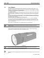
PMS / LMS Axle Play Tester for passenger cars up to 3.5 axle load for commercial vehicles up to 20 t axle load Standard Operating Procedure and User’s Manual Englisch/English D1 0101BA1-GB04 LMS / PMS EDITION Version 4 of the operating manual dated 21.10.1998 D1 0101BA1-GB04 © MAHA GMBH & CO. KG. All rights reserved. Any reproductions of this document, partial or complete, are only allowed with prior consent of MAHA GmbH & Co. KG. All rights reserved in cases of patent granting or registration of design. The contents of this version have been checked with great care. However, errors cannot be fully excluded. Please contact MAHA should you find errors of any kind. Subject to technical change without notice. These instructions are intended for users with previous technical knowledge in the field of vehicle testing technology as well as basic computer knowledge and MS-Windows operating system application. Windows and Windows for Workgroups is a registered trademark of the Microsoft-Corporation. MANUFACTURER MAHA Maschinenbau Haldenwang GmbH & Co. KG. Hoyen 20 D-87490 Haldenwang/Allgäu Telephone: 08374 / 585-0 Telefax: 08374/ 585-499 Internet: e-mail: http://www.maha.de [email protected] SERVICE MAHA Maschinenbau Haldenwang GmbH & Co. KG. - Service dept. Hoyen 20 D-87490 Haldenwang/Allgäu II Hotline: 08374 / 585 + extension 260 for brake testers, test lanes 280 for lifting technology 290 for performance testers, exhaust and air conditioning service equipment Service: Telefax: 08374 / 585-110 bis - 113, - 115 08374 / 585-491 D1 0101BA1-GB04 LMS / PMS TABLE OF CONTENTS 1 General Information .................................................................................................. 1 1.1 1.2 1.3 1.4 1.5 1.6 2 Operations ................................................................................................................. 9 2.1 2.2 3 Operations PMS/LMS .................................................................................................................... 9 Operations PMS 101/LMS 101 .................................................................................................... 10 Maintenance ............................................................................................................ 11 3.1 3.2 4 General .......................................................................................................................................... 1 Safety Instructions ......................................................................................................................... 1 Specification................................................................................................................................... 2 1.3.1 Mechanical Data............................................................................................................. 2 1.3.2 Electrical Data ................................................................................................................ 2 Noise Emission .............................................................................................................................. 3 Safety Guidelines........................................................................................................................... 3 List of Models ................................................................................................................................. 4 Maintenance ................................................................................................................................ 11 Installation of Control Unit............................................................................................................ 11 Appendix A .............................................................................................................. 13 4.1 Maintenance Plan ........................................................................................................................ 13 D1 0101BA1-GB04 III LMS / PMS IV D1 0101BA1-GB04 LMS / PMS 1 General Information 1.1 General The electro-hydraulic test stand PMS or LMS is designed to test vehicle axles and their components for possible wear and tear due to extensive use Two tests plates, integrated into the floor or into a scissor-type lifting platform, are controlled in their forward and sideward movements by switches on the portable lamp. Worn track-rod ends, ball joints, wheel-bearing play and many other defects are immediately detectable during the cross and longitudinal movements of the test plates. The axle play tester facilitates a reliable test even for large and heavy vehicles where a possible wheel-bearing play could hardly be detected by manual shaking, which was common practice in the past. Another advantage of this test stand is its smooth one-handed operation without using a pit lifting device. 1.2 Safety Instructions Safety Instructions are provided to warn about dangerous situations and to help avoid injury to people. The machinery is only to be used for its intended purpose as described in the operating instructions! Only trained authorized personnel may operate the test stand. All work on electrical parts of the equipment is to be carried out by trained, qualified electricians or service technicians only. For safe operation pay attention to the following: Read the standard operating procedures and user`s manual thoroughly! MAHA will not accept and is not liable for any claims for damage or service costs incurred due to noncompliance with these operating instructions. All official Accident Prevention Regulations must be thoroughly complied with! D1 0101BA1-GB04 1 LMS / PMS General Information Test plates in operation are potentially dangerous! Emergency procedures to be followed when coming into contact with hydraulic oil (Safety Sheet DIN 52900, exerpt): Skin ⇒ Thoroughly wash all skin areas with soap and water which have come into contact with oil. Eyes ⇒ Rinse the eyes with clear water for at least 10 minutes! Eventually a doctor should be contacted. Swallowing ⇒ Do not induce vomiting! Give the patient approx. 25 to 50 g medical carbon and 5 to 10 g paraffinum liquidum. 1.3 Specification 1.3.1 Mechanical Data Commercial vehicle Passenger car Total max. axle load 20 t 18 t (LMS 101) 3,5 t Max. axle load per side 10 t 9 t (LMS 101) 1,75 t Max. movement per side 100 mm 100 mm Oil capacity of ,hydraulic unit approx. 8,5 l hydraulic oill SAE 5 Size 750 x 750 mm 625 x 625 mm Installation height 220 mm 134 mm Height above floor 232 mm 150 mm Max. thrust per side 30000 N 11000 N Max. pressure of hydraulic unit per side 120 bar 120 bar Pressure relieve valve included. 1.3.2 Electrical Data Commercial vehicle Power supply 400 V, 3 phases Fuse 16 A slow 16 A slow Cable 5 x 1,5 mm2 5 x 1,5 mm2 Portable lamp Halogen 12 V, 20 W Control 24 V in portable lamp Electric solenoid valves 2 Passenger car 24 V 24 V D1 0101BA1-GB04 General Information LMS / PMS The test stand is remotely controlled via a hand lamp which is equipped with various pushbuttons. The portable lamp is available in two different versions, either with cable remote control (standard equipment) or with infrared transmitter. Technical Data Infrared Lamp Halogen-illuminant Illuminated area approx. 1200 m Luminescence approx. 60 min. Weight appr. 750 g Halogen lamp 4,8 V; 4,4 W Screwed socket Charging box Batteries: 4 NiCd Sub C-size Technical Data Cable Lamp Halogen-illuminant Illuminated area approx. 1200m Gewicht ca. 750 g Halogen lamp 12V; 20 W Plug-in socket Lenght of cable 7,5 m Subject to technical alterations without notice! 1.4 Noise Emission The noise emission value created when the tester is in operation is less than 70 dB (A) in the work area of the operational personnel. 1.5 Safety Guidelines The following points were taken into consideration at construction: The test stand meets the safety demands of the following guidelines: - 89/392/EWG in connection with 91/368/EWG and 93/44/EWG EG-Maschinery guidelines. - 73/23/EWG EG-Low Voltage guidelines. - 89/336/EWG EG -guidelines regarding electro-magnetic tolerance. CE-Declaration of Conformity . Pay attention during operation: The Accident Prevention Regulations of the country in which the lift is being operated apply. The following guidelines apply within the European Union countries: - 89/391/EWG Safety and Health Protection for the Employee. - 89/654/EWG Safety and Health Protection in the Work Area. - 89/655/EWG Safety and Health Protection when using Working Materials. - 89/656/EWG Safety and Health Protetion when using personal Protective Clothing. - 92/58/EWG Safety and/or Health Protection Identification at the Place of Work D1 0101BA1-GB04 3 LMS / PMS 1.6 General Information List of Models The axle play tester of MAHA Maschinenbau Haldenwang is available in many options. The difference in these options is mainly the sequence of movements of the test plates, the design and the use of pushbuttons on the portable lamp. The following drawings will show various pushbutton assignments on the portable lamp, but are by no means complete. The portable lamp is available in two different versions, either with cable remote control or with infrared transmitter. The PMS/LMS 101 version is directly operated via a lever and a portable lamp. The test stand is operated via toggle switches on the portable lamp which have, depending on the version, various functions. They facilitate, e.g. the control of longitudinal/cross and diagonal movements of the test plates. The portable lamp is en-or disabled by on of the switches. As soon as the test plates are in operation, the hydraulic control unit enables automatically. The hydraulic control unit is equipped with an automatic cut-off which is set at approx. 7 sec; after this time has elapsed with no switch having been actuated within this time, the hydraulic control unit switches off. As an option, the portable lamp is also available with an infrared transmitter. When not in use, the infrared lamp should always be placed in the charging box with the reflector on top! The accumulator-charging period of the lamp is approx. 14 hours. A LED will blink on the recharging box indicating that the battery is recharged properly. Infrared lamp Only 4.5 W halogen bulbs should be used with the infrared portable lamp, otherwise the longevity of the accumulator can be substantially reduced. Used nickel-cadmium cells and defective instruments should be disposed off at special waste depots! 4 D1 0101BA1-GB04 General Information LMS / PMS The following pushbutton functions also apply for infrared lamps: PMS 3/1 LMS 20/1 PMS 3/1QG LMS 20/1QG PMS 3/1LG LMS 20/1LG PMS 3/1QLG LMS 20/1QLG LMS 20/1QLG The following test stands are equipped with a synchronizing switch to synchronize the longitudinal and cross movements which are normally opposite. PMS 3/2 LMS 20/2 PMS 3/2QG LMS 20/2QG PMS 3/2LG LMS 20/2LG PMS 3/2QLG LMS 20/2QLG D1 0101BA1-GB04 5 LMS / PMS General Information The following test equipment may be installed in MAHA DUO lifting platforms: PMS 3/2S PMS 3/2SH PMS 3/2D PMS 3/2DH 6 D1 0101BA1-GB04 General Information LMS / PMS The following configuration applies to this test stand: Service technicians should identify the test lamp in question on this page and enter the applicable push button configuration. D1 0101BA1-GB04 7 LMS / PMS 8 General Information D1 0101BA1-GB04 LMS / PMS 2 Operations 2.1 Operations PMS/LMS Enable test stand by mains switch. Drive vehicle onto test plates. Operate test plates by pushbutton functions of the portable lamp as described in Chapter 1, Page 6. Do not run hydraulic unit longer than absolutely necessary, as this may cause damage to the pump! Some axle play testers are equipped with a synchronizing switch on the control panel, to control longitudinal and/or cross movement of the plates. Operate brake in case of plate movement in driving direction, forward and reverse, as this movement might be repeated by the rotating wheels. After termination of the test, switch off lamp and hydraulic unit by the toggle switch on the portable lamp. Drive vehicle from test plates. Place portable lamp in the charging box when not in use. Attempt to make the vehicle wheels slip on the plates, as this will facilitate testing for inacceptable play Protect portable lamp against impacts to extend the life of its bulb. D1 0101BA1-GB04 9 LMS / PMS 2.2 Operations Operations PMS 101/LMS 101 On PMS 101 and LMS 101 axle play testers, the moving direction of the test plates is controlled via a hand lever. The hand lever can have the following two positions: Longitudinal movement Cross movement The hand lever is located at the test plates. The remote control portable lamp is equipped with two toggle switches. The first toggle switch has two switch positions, 0 and I, which en-or disable the lamp. The second toggle switch with switch positions I, 0 and II facilitates the control of longitudinal and cross movement of the test plates. 10 D1 0101BA1-GB04 LMS / PMS 3 Maintenance 3.1 Maintenance Remove covers every 200 operating hours or at least every three months and grease guideways with a grease gun. Check guide rod bolts for tightness. Retighten if necessary. Regularly check the oil level in the hydraulic tank. The oil level should be between the two marks. Change hydraulic oil every two years. Use approximately 8,5 l HLPD 32 hydraulic oil. Refer to maintenance plan, appendix A. If the sliding cylinder or the guide rod need to be replaced, the attachment screws must be glued in with Loctite 243! 3.2 Installation of Control Unit Authorized service technicians have special documents (e.g. pit plans) at their disposal for the installation and dismantling of the PMS/LMS. The axle play tester PMS/LMS may only be installed by qualified technicians! All work on electrical parts of the equipment is to be carried out by trained qualified electricians or service technicians of the manufacturer or its dealers only! MAHA warranty coverage does not apply to damage caused by improper installation or dismantling. This regulation will also apply during the regular warranty period. D1 0101BA1-GB04 11 LMS / PMS 12 D1 0101BA1-GB04 LMS / PMS 4 Appendix A 4.1 Maintenance Plan D1 0101BA1-GB04 13 LMS / PMS 14 D1 0101BA1-GB04