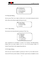
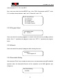
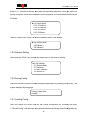
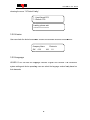
1
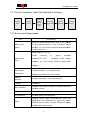
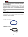
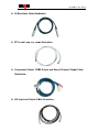
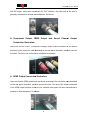
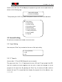
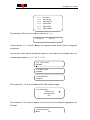
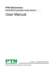
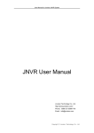
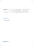
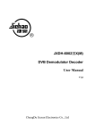
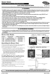
HD - IRDIRD - V3
User’
User’s Manual
Manual
Broadcast integrated receiver decoder for satellite and
and terrestrial
program injection for broadcast headends. Supports advanced
transport stream operations for RF, IP, and ASI.
Thor Broadcast Group - Los Angeles, California
California.
H-HD-IRD-V3 User Manual
DIRECTORY
Chapter 1 Product Overview ................................................................
......................................... 1
1.1 Outline ................................................................................................
................................
...................................... 1
1.2 Features ................................................................................................
................................
.................................... 1
1.3 Specifications...........................................................................................
................................
........................... 2
1.4 Principle Chart .........................................................................................
................................
......................... 3
1.5 Appearance and description ................................................................
................................... 3
Chapter 2 Installation Guide ................................................................
......................................... 5
2.1 Optional Cabling ......................................................................................
................................
...................... 5
2.2 Installation Preparation ................................................................
........................................... 5
2.3 Wire’s Connection ...................................................................................
................................
................... 7
2.4 Signal Cable Connection ................................................................
......................................... 8
Chapter 3 Operation ....................................................................................
................................
.................... 13
3.1 Main Interface .........................................................................................
................................
......................... 13
3.2 General Setting ......................................................................................
................................
...................... 14
Chapter 4 NMS Setting ................................................................................
................................
................ 21
Chapter 5 Troubleshooting ................................................................
......................................... 21
H-HD-IRD
IRD-V3 User Manual
Chapter 1 Product Overview
1.1 Outline
HD-IRD-V3 HD IRD is Thor’s newly
new designed IRD with added Program control features,
integrated FPGA, and a video monitoring
monitor
LCD on the front panel.. The LCD can display
programs from ASI,DVB-S2, or IP sources
sources. Dual slots for industry standard CAM modules
module
can be used to multiplex and de-encryptcomplete
de
carrier TS streams.
s.
Additional
programs can be inserted to the MPTS for ASI and IP outputs, while simultaneously
decoding a program to scaled or native outputs on HD-SDI,
HD SDI, HDMI, YPbPr, and
CVBS.Additionally,
Additionally, digital audio output with Dolby passthrough is provided on optical and
XLR connectors, analog balanced and unbalanced is also provided.
HD-IRD
IRD-V3 supports
one channel (Tuner,ASI or IP) de--scrambling and provides transparent signal output. User
can operate the device by using front panel LCD or NMS browser login. Additional features
include the ability to pass the encrypted TS from the input to a second
d ASI output in
addition to decrypted TS output.
1.2 Features
Generation 3 Processor Core
Front Panel LCD for confidence monitoring
Adaptive sensor based environment control
Dual CAM Conditional Access card bays
Decodes both MPEG-2
2 and H.264 programs
Re-multiplexer and descrambler
scrambler embedded
Supports DVB-ASI
ASI daisy chain and Cascading
Support 4 ASI, 1 CVBS, 1 YPbPr, 1 HD/SD
HD/SD-SDI, 1 XLR and RCA,, 1 S/P DIF audio, 1
HDMI, and IP output
Compatible for both HD and SD
SupportsOutputs at 1080I, 720P, SD PAL/NTSC.
PAL/NTSC identified automatically
1
H-HD-IRD
IRD-V3 User Manual
Two CI Slot PCMCIA interfaces.
interface
Two independent CAM
M modules:
module Max decryption of 8 SD programs
Supports BISS “mode 1” and “mode
“
E”
Three RJ-45 interfaces:
s: Management, and dual TS outputs
Maintains programming after power failure
Supports Closed Captioning streams for both 608 and 708 standards
Supports manipulation of TS metadata from DVB-S2
DVB
streams
Supports 1 ASI input, tuner input (supporting DVB-S/S2), IP input(UDP)
UDP)
SupportDVB-S/S2 demodulation.
demodulation
1.3 Specifications
Input Interface
Tuner
ASI
IP
Video Output
1 tuner(DVB-S/S2)
1 ASI IN
1 IP
2 groups separate output ports (each group has
2 channels)
1xCVBS, 1xYPbPr, 1xHD/SD-SDI,
SDI, 1 x HDMI
Audio Output
SPDIF Output
XLR, L/R
1 SPDIF
ASI Output
Output Port
Input Level
-65~-25dBm
Input Frequency
950~2150MHz
Symbol Rate
2-45M symbols
Constellation
FEC Code Rate
QPSK, 8PSK
1/2, 3/5, 2/3, 3/4,4/5, 5/6, 8/9,9/10
Ethernet Port
10/100M
Protocols
TS Over IP : UDP, NMS : UDP
Dimensions ( L×W×H)
482mm*360mm*44mm
Approx weight
3.2kg
Power
<20W(Max)
Temperature
0~45℃(Operating), -20~80
20~80℃(Storage)
NMS Port
Miscellaneous
2
H-HD-IRD
IRD-V3 User Manual
1.4 Principle Chart
1.5 Appearance and description
Front Panel Illustration:
Indicator area: Status LED’s are provided for primary functions
1
2
3
4
5
6
7
8
9
10
LCD Display
Alarm Indicator
ndicator
Power Indicator
ndicator
Up/Down/Left/Right Buttons
Enter-confirming
confirming Key
Menu Key
Lock Key Indicator
ndicator
LCD Monitor
Switch Button
PCMCIA interface
Rear Panel Illustration
3
H-HD-IRD
IRD-V3 User Manual
1
2
RF IN Interface
DVB-S/S2
S/S2 Loop Out Interface
3
4
5
IP IN/OUT Interface
ASI IN Interface
ASI Out3
ut3 and ASI Out4 Interface: Output Single TS Stream from
tuner.
ASI Out1 and ASI Out2 Interface: Output multiplexed or
separated TS Stream from tuner, ASI and IP.
10MHz IN and 10MHz LOOP interface
1PPS IN and 1PPS LOOP interface
HDSDI-OUT Interface:
Interface: HD/SD digital parallel output interface
USB interface:: Software updating.
HDMI Output Interface
nterface
SPDIF: Digital
igital audio output interface
YPbPr: Audio and Video component output interface
CVBS: Composite video and audio output interface
Audio (L/R channel) output interface
NMS Ethernet Port(10-100Mbps)
Port(10
Balance audio output interface
Integrated power switch and socket
Grounding Wire
6
7
8
9
10
11
12
13
14
15
16
17
18
19
4
H-HD-IRD
IRD-V3 User Manual
Chapter 2 Installation Guide
2.1 Optional Cabling
Thor will provide standard interface cabling for the end users application. Please check the
included packing list that came with your order and confirm that all items are present.
Typically bundled cabling and packing lists will include the following items.
it
HD-IRD-V3 HD IRD
User’s Manual 1pcs
Power Cord
1pcs
1pcs
XLR Interface Cable
2pcs
RF In and Loop Out Cable
Component Output, CVBS Output and Sound Channel Output Cable
3pcs
pcs
ASI Input and Output Cable
1pcs
1pcs
Please contact Thor if you are missing any required cabling.
2.2 Installation Preparation
Please refer to the following section for installation procedures. This chapter is intended
to be used along with the I/O diagrams from the previous chapter.
The main content of this chapter includes:
includ
Checking the packing list for missing items
Preparing relevant environment for installation
Installing HD IRD
Connecting signal cables
Connecting communication port (if it is necessary)
5
H-HD-IRD
IRD-V3 User Manual
2.2.1 Device'ss Installation Flow Chart Illustrated as following
following:
Inventory
Check
Mounting
In Rack
Connecting
Grouding
Wire and
Power
Cord
Connecting
Signal Wire
Setting
Parameter
Running
Device
2.2.2 Environment Requirement
Requirements
Item
Machine Hall
Space
Requirement
When user installs machine frame array in one machine
hall, the distance between 2 rows of machine frames
should be 1.2~1.5m and the distance against wall should
be no less than 0.8m.
Electric Isolation, Dust Free
Volume
Machine Hall
Floor
resistivity
of
ground
material:1X10⁷~1X10¹⁰Ω , Grounding
antianti-static
current
limiting
resistance: 1M (Floor bearing should be greater than
450Kg/㎡)
450Kg/
Environment
Temperature
℃(sustainable ),0~45℃(short time),
5~40℃
installing air-conditioning
air
is recommended
Relative
Humidity
20%~80% sustainable 10%~90% short time
Pressure
86~105KPa
Door & Window
Installing rubber strip for sealing door
door-gaps
gaps and dual level
glasses for window
Wall
It can be covered with wallpaper, or brightness less paint.
Fire Protection
Fire alarm system and extinguisher
Power
Requiring device power, air-conditioning
conditioning power and
lighting power are independent to each other. Device
power requires AC power 100-240V
100
50-60Hz 2A.. Please
carefully check before running.
6
H-HD-IRD
IRD-V3 User Manual
2.2.3 Grounding Requirement
It is important to keep this device grounded to ensure all of the modules function
correctly. Correctly grounding the device will also help prevent and electrical
interference, lightening, ETC. Also it helps reject minor interference that may disrupt
the devices
evices ability to function smoothly. General rule of thumb, make sure the device is
grounded when installing anywhere.
Always use copper wire. When applied correctly the ground must be wrapped well to
ensure maximum conduction so it can reduce any high frequencies.
frequencies. The copper
ground wire should also be as short and thick as possible..
possible.
Installer must make sure that the two ends of the ground are well conducted and have
appropriate anti-rust
rust properties. .
It is prohibited to use any other device as part of grounding electric circuit
The area of the conduction between grounding wire and device’s frame should be no
less than 25mm2.
2.2.4 Frame Grounding
All the machine frames should be connected with protective copper strip. The grounding
wire should be as short
rt as possible and avoid circling. The area of the conduction between
grounding wire and grounding strip should be no less than 25mm2.
2.2.5 Device Grounding
Connecting the device’s grounding rod to frame’s grounding pole with copper wire.
2.3 Wire’s Connection
The grounding wire
e conductive screw is located on the right side of the rear panel, and the
power switch, fuse, power
er supply socket is just beside,
beside whose order goes like this; power
switch is on the left ,power supply socket is on the right and the fuse is between them.
Connecting Power Cord
7
H-HD-IRD
IRD-V3 User Manual
User can insert one end into power supply socket, while insert the other end to AC power.
Connecting Grounding Wire
When the device solely connects to protective ground, it should adopt this power in an
independent
pendent way. Especially if you share the same ground
d with other devices. When the
device adopts both currents in a united way, the grounding resistance should be smaller
than 1Ω.
Caution:
Before connecting power cord to HD IRD, user should set the power switch to “OFF”.
“OFF”
2.4 Signal Cable Connection
The signal connections include the connection of input signal cable and the connection of
output signal cable. The details are as follows:
2.4.1HD-IRD-V3HD IRD Cables Illustration:
IP Input Cable Illustration:
llustration:
HDMI Cable Illustration
8
H-HD-IRD
IRD-V3 User Manual
XLRInterface Cable Illustration:
llustration:
RF In and Loop Out Cable IIllustration:
Component Output,
utput, CVBS Output and Sound Channel Output Cable
Illustration:
ASI Input and Output Cable Illustration:
Illustration
9
H-HD-IRD
IRD-V3 User Manual
1PPS& 10MHz Input and Loop-outCable
Loop
Illustration
2.4.2HD-IRD-V3 HD IRD Satellite Receiver Signal Cable Connection
Illustration:
RF IN and LOOP OUT Connection Illustration:
Users can find the RF IN and LOOP OUT interface on the device according to the
connector mark described on the rear panel illustration
illustration, connect the cable as shown below
below.
One end is connected to the RF IN interface of satellite receiver while the other end is
connected to the satellite signal source equipment or LOOP OUT interface of the previous
satellite receiver when several satellite receivers are series connection. As follows:
ASI IN and ASI OUT Connection Illustration:
Users can find the ASI IN and ASI OUT interface on the device according to the connector
mark described on the rear panel illustration,connect
illustration
the cable as shown.. One end is
connected to ASI IN interface of the HD IRD,
IRD, the other end is connected to any device that
10
H-HD-IRD
IRD-V3 User Manual
has ASI output, while when connected ASI OUT interface, the other end of the wire is
generally connected to encoder and multiplexer. As follows:
Component Output, CVBS Output and Sound Channel Output
Connection Illustration:
Users can find the YPbPr, CVBS and Left/Right sound
sound channel interface on the device
according to the connector mark described on the rear panel illustration,
illustration, and then connect
the cable. The other end of the wire is connected to encoders.
HDMI Output Connection Illustration:
Users can find the HDMI interface on the device according to the connector mark described
on the rear panel illustration, and then connect the wire. One end of the wire is connected
to the HDMI output interface of the HD IRD, whilethe
whilethe other end of the wire is connected to
encoder or other equipment.. As follows:
11
H-HD-IRD
IRD-V3 User Manual
IP Output Connection Illustration:
Users can find the IP IN/OUTPUT interface on the device according to the connector mark
described on the rear panel illustration, and then connect the wire
wire.One
One end of the wire is
connected to the IP input/output
output interface of the HD IRD,the other end of the wire is
connected to devices with IP OUT/INPUT as
a follows:
XLR Output Connection Illustration:
Users can find the XLR interface on the device according to the connector mark described
on the rear panel illustration, and then connect the wire.One
wire One end of the wire is connected to
the XLR output interface of the HD IRD,the
IRD,t other end of the wire is connected toIP
to encoder.
As follows:
10MHz IN &1PPSIN
PPSIN Connection Illustration:
You can find the 1PPS and 10MHz
Hz interfaces on the device according to the connector
mark described on the rear panel illustration, and then connect the wires
wire on the cccondition
that the SFN solution is involved.
involved.One end of the wireis connected to the 1PPS
1
IN and
10MHz INinterfaces
nterfaces of the HD IRD, and the other end of the wires is connected to
toGPS as
follows:
12
H-HD-IRD
IRD-V3 User Manual
Chapter 3 Operation
The front panel of HD-IRD-V3HD
HD IRDis
IRD the user-operating
operating interface and the equipment can
be conveniently operated entirely from the front panel. All available configuration settings
can be accessed through the interface menu tree. Please refer to the following guide for
assistance:
Keyboard
rd Function Description:
MENU: Cancelcurrent entered value, resume
resum previous setting; Return to previous menu.
ENTER:Activatetheparameters
eters
which
need
modifications,or
modifications,or
confirmthe
change
aftermodification.
LEFT/RIGHT: Choose
hoose and set the parameters.
UP/DOWN: Modify activated parameter or paging up/down when parameter is inactivated.
LOCK:Locking
Locking the screen / canceling the lock state. After pressing lock key, the system will
question the users to save present setting or not. If not, the LCD will display the current
configuration state.
3.1 Main Interface
13
H-HD-IRD
IRD-V3 User Manual
Switch on the IRD, the LCD will display the equipment type and current output stream as
shown on the following page,
DVB-S2 BTS HD IRD
Out Stream 00.006Mbps
Then pressing the “LOCK” key on the front panel
panel to enter to the main menu as below:
►1 Input Setting
2 Output Setting
3 Decoder Setting
4 Descramble Setting
5 Network Setting
6 Saving Configuration
7 Loading Configuration
8 Version (SNMP)
9 Language
3.2 General Setting
All options are available from these 9 root menu trees.
3.2.1 Input Setting
User can press “Enter” key to enter into the menu of the input setting.
1.1 Tuner (DVB-S2)
1.2 ASI
1.3 IP
3.2.1.1 Tuner In
Here we take 1.1 Tuner (DVB-S2)
S2) signal in as an example:
The page menu from 1.1 to 1.3 represents the tuner, ASI and IP input ports of the IRD.
User can multiplex the input programs from any port to output any program or all the
programs at the same time. By pressing the “Enter” key, the device will take a while to
analyze the input TS or signal and then display the program list at the submenu, say,
1.1.1-1.1.6
14
H-HD-IRD
IRD-V3 User Manual
1.1.1
1.1.2
1.1.3
1.1.4
1.1.5
1.1.6
Prog Parse
Sat Freq Set
LNB Freq Set
Symbol Rate
LNB Voltage
22KHz Switch
By pressing the “Enter” key to enter the submenu of 1.1.1
1.1.1 Prog: 00
Mux: 00
At the submenu 1.1.1, the LCD displays the program number and the count of programs
multiplexed.
User can also check and set the satellite frequency, LNB frequency and symbol rate of its
corresponding submenu “1.1.2”, “1.1.3
1.1.3”, “1.1.4”.
1.1.2 Sat Freq Set
3840MHZ
1.1.3 LNB Freq Set
5150MHz
1.1.4 Symbol Rate
27500KHz
At the submenu 1.1.5, user can decide which LNB voltage to apply.
1.1.5 LNB Voltage
Vertical (13V)
Horizontal (18V)
OFF
At the submenu 1.1.6, user can choose to turn on the 22 KHz to search the programs from
KU band.
1.1.6 22 KHz Switch
►OFF
15
ON
H-HD-IRD
IRD-V3 User Manual
3.2.1.2 ASI IN
Return to the upper menu to enter into 1.2 ASI IN, and users can view the program number
and the count of programs multiplexed.
multiplexed
1.2.1 Prog Parse
Prog: 00
Mux: 00
3.2.1.3 IP IN
Entering into 1.3 IP, it displays below page:
► 1.3.1 Prog Parse
1.3.2
1.3.3
Input IP Addr
Input Port
Similarly, 1.3.1 Prog Parse offers the same information with 1.1.1 and 1.2.1.
User also could check and set the input IP address and input port of its corresponding
submenu “1.3.2”, “1.3.3”.
1.3.2 Input IP Address
224.002.002.002
1.2.1 Input port
1001
3.2.2 Output Setting
User can press “Enter” key to enter into below menu of the output setting and set its
corresponding parameters or functions under the right submenus.
.
16
H-HD-IRD
IRD-V3 User Manual
►2.1 Multiplex Set
►
2.2 Output Bit rate
2.3 Tran stream ID
2.4 Original/Net ID
2.5 IP Output
3.2.3 Decoder Setting
User can press “Enter” key to enter into below menu of the decoder setting and execute
video setting, audio setting, program selecting and search.
►3.1Video Setting
►
3.2 Audio Setting
3.3 Program Select
3.4 Search
3.2.3.1 Video Setting
User can enter into below submenu by pressing the “Enter” key.
►3.1.1Resolution
3.1.2 Standard
3.1.3 Subtitle
3.1.4 CC Switch
3.1.5 Finger Switch
3.1.6 Aspect Ratio
Users canselectfrom
from the assortment of presets of the following: Resolution
esolution,Standard,
&Aspect Ratio; and choose whether to turn on or turn off the following: Subtitle, CC
Switch,&
& Finger Switch of their corresponding submenus.
submenu
3.2.3.2 Audio Setting
Users can enter into below submenu by pressing the “Enter” key, then
hen select the audio,
choose the ES mode (consists
consists of stereo, left channel, right channel) and adjust the volume
17
H-HD-IRD
IRD-V3 User Manual
under submenu 3.2.1, 3.2.2, and 3.2.3
3.2.3.
Also, users can select the Audio SPDIF from “Auto,, PCM, Compressed and OFF”
OFF under
3.2.4. andalso choose between “Auto
Auto” and “2 Channels” under 3.2.5.
►3.2.1Audio
►
Select
3.2.2 ES Mode
3.2.3 Volume
3.2.4 Audio SPDIF
3.2.5 Audio Channel
3.2.3.3Program Select
3.3Program Select
►
►1
CCTV-1
Users
sers can select the inputting programs to encode under this menu by pressing up/down
button. Here “1” represents the program number and “CCTV-1” represents the program
name.
3.3.3.4Search
Users can search the quantity of programs after entering this menu.
3.4Search
Total Programs: 8
3.2.4 Descramble Setting
User can press “Enter” key to enter into below menu of the descramble setting.
setting.The detailed
operation about the descramble function will be explained on the NMS operation part
(Chapter 4).
►4.1Card Setting
►
4.2 BISS
18
H-HD-IRD
IRD-V3 User Manual
Enter in 4.1, it shows as follows, and under corresponding submenu, users can select the
source of signals, check card information, select programs
programs to be descrambled, and choose
CI bitrate.
►4.1.1Input
4.1.1Input Select
4.1. A Card Info
4.1.2
4.1.3 B Card Info
4.1.4 Pro Select
4.1.5 CI Bitrate
Under
nder 4.2 BISS menu, users can choose between Mode 1 and Mode E.
►4.2.1Select
4.2.1Select Mode
4.2. Mode 1
4.2.2
4.2.3 Mode E
3.2.5 Network Setting
User can press “Enter” key to enter into below menu of the network setting.
►5.1IP
5.1IP Address
5. Subnet Mask
5.2
5.3 Gateway
5.4 MAC Address
5.5 Service IP
3.2.6 Saving Config
User can choose to save the current configured parameters by pressing ENTER key. The
system displays following page:
Saving, please wait:
Erasing
rasing…….
3.2.7 Loading Config
User can restore the device into the last saved configuration by choosing the menu
7.1”Saved Config”, and also user can restore the device into factory default configuration by
19
H-HD-IRD
IRD-V3 User Manual
choosing the menu 7.2”Default Config”.
7.1 Load Saved CFG
7.2 Default CFG
Loading, please wait:
>>>>>>>>>>>>>>>>
3.2.8 Version
User can check the device’ss hardware version and software version at this submenu:
Company Name
SW
0.22
Electronic
HW
1.0
3.2.9 Language
HD-IRD-V3 HD IRD has two language
language versions: English and Chinese. For convenient
system setting and device operating, user
u
can select the language version freely based on
their demands
20
H-HD-IRD
IRD-V3 User Manual
Chapter 4NMS Setting
Network Management System Profile
In addition to the front panel LCD interface, the unit can also be managed and configured
through any standard modern web browser. The default IP address is typically
192.168.1.136, however this may be modified during configuration prior to shipping. The
unit’s
s management IP address can be easily set or identified from the front panel interface.
Please refer to the previous section for assistance.
Chapter 5 Troubleshooting
THOR’ several levels of inspection for quality control. All systems shipped by Thor are
fully tested and visually inspected after manufacture.
Additionally, all units are
re-inspected and pre-configured
configured prior to shipping. Under most circumstances, Thor offer
offers
free configuration service for most equipment. Thor can set operating parameters prior to
shipping, and ensure trouble free operation and installation.
Prevention Measure
Please ensure that the environment remains within 0 to 45 °C
Provide adequate ventilation
ntilation to the heat sinks and side vents.
Check the input AC voltage,, please use appropriate power supplies
Check that all signal cables are securely installed and nothing is loose.
Frequently switching on/off device is not recommended. Please allow at least 10
seconds between power cycles.
21