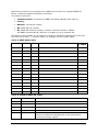
1
JANIS 3.4 USER’S GUIDE MAY 2012 Table of content Table of content 3 I. What is JANIS? 6 A. Introduction ................................................................................................... 6 B. What’s new in version 3.4 ................................................................................ 6 C. History .......................................................................................................... 7 II. First steps 9 A. Content of JANIS 3.4 DVD ................................................................................ 9 B. Requirements and compatibility ....................................................................... 10 1. Java .......................................................................................................... 10 2. Hardware configuration ................................................................................ 10 C. Installation.................................................................................................... 10 D. Starting JANIS............................................................................................... 10 III. General overview 11 A. The “Browser” window .................................................................................... 11 1. Database Tree ............................................................................................ 12 2. Chart of Nuclides......................................................................................... 13 3. Nuclide Explorer .......................................................................................... 16 B. The “Renderer” window .................................................................................. 17 1. Display panels ............................................................................................ 18 2. Selection Tree ............................................................................................. 18 3. Data parameters ......................................................................................... 19 C. Plot views ..................................................................................................... 21 1. 2. 3. 4. Plotter basic parameters .............................................................................. 21 Plotter advanced parameters ........................................................................ 22 Plots parameters ......................................................................................... 26 Saving plots ............................................................................................... 26 D. Table views ................................................................................................... 28 1. Tabler basic parameters ............................................................................... 28 2. Tabler advanced parameters......................................................................... 29 3. Saving tables .............................................................................................. 30 E. Text views..................................................................................................... 31 F. Decay path views ........................................................................................... 32 1. Decay paths parameters .............................................................................. 33 2. Decay path advanced parameters ................................................................. 34 3. Saving decay paths ..................................................................................... 34 G. Upgrading JANIS ........................................................................................... 35 H. Customizing JANIS ......................................................................................... 35 IV. Data 36 A. Cross-sections and resonance parameters ......................................................... 36 B. Energy distributions ....................................................................................... 38 C. Angular distributions ...................................................................................... 40 3 D. Energy-angle distributions .............................................................................. 41 E. Decay data .................................................................................................... 41 F. Fission yields ................................................................................................. 41 G. Photon production data .................................................................................. 43 H. Covariance data ............................................................................................ 43 V. The search tool 45 A. Search dialog ................................................................................................ 45 1. 2. 3. 4. Criteria panel .............................................................................................. 46 Actions panel .............................................................................................. 47 Results panel .............................................................................................. 48 History drop-down ....................................................................................... 48 B. Evaluated data (ENDF) search ......................................................................... 48 C. Experimental data (EXFOR) search ................................................................... 50 D. Bibliographical (CINDA) search ........................................................................ 52 E. Resonances search ......................................................................................... 54 F. Decay lines search ......................................................................................... 55 VI. Computations and weighting 56 A. Computation dialog ........................................................................................ 56 1. Definition of new computations ..................................................................... 56 2. Reusing computations .................................................................................. 57 B. Weighting of cross sections ............................................................................. 58 1. Group structure .......................................................................................... 59 2. Spectrum ................................................................................................... 60 VII. JANIS features through examples 62 A. Comparing data ............................................................................................. 62 1. Manually comparing evaluated data against experimental data ......................... 62 2. Using “Compare with Evaluated data” tool ...................................................... 63 B. Searching data .............................................................................................. 64 C. Computing the ratio between two evaluations ................................................... 64 VIII. JANIS databases 66 A. Database Load dialog ..................................................................................... 66 B. Connecting to NEA remote database ................................................................. 66 C. Viewing data directly from a file ....................................................................... 66 D. Creating a personal database .......................................................................... 67 1. Import wizard dialog.................................................................................... 67 2. Import progress dialog................................................................................. 70 3. Import dialog .............................................................................................. 70 IX. Troubleshooting 72 A. Bug report dialog ........................................................................................... 72 B. Known problems ............................................................................................ 73 C. Start-up problems .......................................................................................... 73 1. Windows .................................................................................................... 73 4 2. Linux/Unix.................................................................................................. 74 D. Databases problems ....................................................................................... 74 1. Restore default databases ............................................................................ 74 2. Connection errors ........................................................................................ 75 E. Memory problems .......................................................................................... 76 F. Speed problems ............................................................................................. 77 X. References 78 XI. Acknowledgements 79 5 I. What is JANIS? A. Introduction Nuclear data are fundamental to the development and application of nuclear science and technology. The knowledge of these data is required in all fields where radioactive materials and nuclear fuels are present. This represents a wide range of applications. Nuclear data are thus needed for a variety of users including reactor and fuel cycle physicists, engineers, biologists and physicians. Nuclear data involve radioactive decay properties, fission yields and interaction data over a wide energy range and for different projectiles (cross-sections, resonance parameters, energy and angular distributions…). These data are structured into standardised formats to allow their exchange among users and their treatment with specialized computer codes. Specific formats exist for experimental data (EXFOR), evaluated data (ENDF, ENSDF) or processed data (PENDF, GENDF) and relational databases are used to store and disseminate the data. However, the quantity of data required is so large that it is not always easy for an end-user to access the information needed for his specific application. Java-based Nuclear Information Software (JANIS) is a display program designed to facilitate the visualization and manipulation of nuclear data. Its objective is to allow its user to access numerical values and graphical representations without prior knowledge of the storage format. It offers maximum flexibility for the comparison of different nuclear data sets. B. What’s new in version 3.4 New functionalities: Support of recent changes in ENDF format: Extension of the fission energy release format (MF1/MT458) New format for Resolved Resonance Parameters : R-Matrix Limited Format (MF2, LRF=7) Decay paths viewer has been redesigned to provide a clearer display and more customization options The database provided on the DVD includes the recently released libraries: JEFF-3.1.2 (2012) ENDF/B-VII.1 (2011) TENDL-2011 TALYS evaluated nuclear data library Corrected bugs and improved functionalities: Resolved and Unresolved Resonance Parameters display has been extended Database connection dialog has been simplified An option “Unselect Others” was added in Renderer selection component EXFOR searches with ‘Product A’ where not retrieving results ENDF parent fission yields distributions (Z, A, N) were empty (empty plot, empty table) CINDA searches ‘Open results’ was sometimes generating NullPointerException 6 C. History JANIS is the successor to JEF-PC, a software developed in the eighties and nineties by the OECD Nuclear Energy Agency, the CSNSM-Orsay and the University of Birmingham. Basically, all the features available under JEF-PC were reproduced (cross-section display in pointwise and groupwise format, decay data and fission yield display) and several others were added (resonance parameters, energy and angle distributions, cross-section uncertainties…). Additionally, all the former limitations were removed (number of data sets displayed, etc.) and the new software is more flexible and ergonomic. JANIS users can view their own evaluated or processed data starting from any ENDF formatted file or from GENDF libraries. As JANIS is written in the Java language, it runs on almost all computer operating systems (UNIX, Windows and Macintosh). The first version of JANIS (1.0), released in October 2001, was used by more than 700 users around the world. Versions 2.0 and 2.1 have introduced: Management of the data through a relational database. One of the limitations of JANIS 1.0 was its structure of data. The basic data (contained in the original ENDF and EXFOR files) had to be converted into an internal structure (serialized Java objects). This option allowed a very quick access to the data. However, the data could not be easily updated and the structure was highly dependent on the classes used to generate the data. In particular, the structure of data became obsolete when these classes were updated. To solve this problem, a new strategy was implemented in versions JANIS-2.0 and above. The software accesses directly the text files (eventually zipped in order to reduce the required storage size) and the tables of contents of these files (the ENDF dictionary for instance) are contained in a relational database. This enables both quick access to the data and a better separation between the methods (classes) and the data itself. Access to the CINDA database and link between CINDA and EXFOR. Basically, the features of CD-CINDA were implemented in JANIS and a link to the EXFOR works was added. Access to NUBASE data. Generalization of the computational features available in conjunction with interaction data; these features (such as linear combinations, ratios of data) were restricted to cross-section data. It is now possible to perform more advanced combinations such as a product of cross sections with energy and angular distribution. Access to centralized data (available on the NEA server) through the widely used HTTP protocol. This allows most users to take advantage of NEA remote databases. Version 3.0 has introduced: 7 Access to original EXFOR data: previous versions of JANIS were using a simplified EXFOR format, named EXFOR Computational Format which was the result of a conversion of EXFOR content. This conversion was losing a great part of available experimental data, mainly because the Computational Format was limited to cross-sections, angular/energy distributions. By reading the original EXFOR format directly, experimental data available in EXFOR can now be displayed by JANIS (fission yields for example). Vectorial and customizable plots: the plotting component has been completely rewritten to be vectorial instead of rasterized. This means that previous plots were made by drawing pixels directly, whereas in version 3.0 plots are drawn with lines and shapes. This allows setting line style and width for continuous plots but also to increase quality of exported images and print. Rasterized plots (in pixels) were fine and fast for screen display but pixels were visible on prints because resolution of printers is much higher than resolution of screens. Vectorial plots also allow saving them in truly vectorial formats like Postscript (PS/EPS) and Windows Metafiles (WMF/EMF). These exported plots can be further scaled without losing quality, the Windows Metafile formats being especially interesting for inclusion in Microsoft Word documents. Tabular view of almost all data: it is now possible to obtain a tabular display of data like angular distributions or energy/angle distributions. This functionality has been requested for a long time. As JANIS tables are exportable in CSV text file some users take profit of JANIS nuclear formats parsing implementation to use the data in their own applications. Version 3.1 has introduced: Display of photon production (MF12-15) Continuous Beta spectra (MF8/MT457); implementation of BTSPEC (A. Tobias et al.) Isobaric fission yields, i.e. distribution in terms of Z or N for a given A. Parent fission yields have been visually reorganized. New tool to compare EXFOR data with evaluated libraries or evaluated libraries between them. This tool replaces the old “Compare explorer” Version 3.2 has introduced: Display of evaluated covariance data (MF33) Support for additional NJOY covariance formats: COVFILS (ERRORR) and BOXER ( COVR) New highly compressed format. This new format is used to store data files on the DVD. All evaluated libraries in the NEA remote database have been processed in a consistent way using NJOY. The following derived data are now available: Gas production cross sections (MF3/MT203-207) KERMA cross sections (MF3/MT301,443) Damage cross sections (MF3/MT444) Thermal scattering cross sections (MF3/MT221-250) Version 3.3 has introduced: PDF format for saving plots Smoother plots on screen and in saved pictures (Anti-aliasing) Improvements of the nuclide chart and ‘Goto’ dialog Decreased memory usage ‘File Open’ dialog can automatically detects input file format 8 II. First steps A. Content of JANIS 3.4 DVD The software and a selection of recent nuclear data were packaged to produce the new release JANIS-3.4. The selection of data includes: evaluated nuclear data libraries processed at 300 K: BROND-2.2 CENDL-3.1 EAF-2010 ENDF/B-VII.1 FENDL-2.1 IRDF-2002 JEF-2.2, 3.1, 3.1.1, 3.1.2 JENDL-4.0 JENDL-AC-2008, JENDL-AN-2005, JENDL-FPDD2000, JENDL-HE-2007, JENDLPD-2004 PADF-2007 RUSFOND-2010 TENDL-2011 (part only, complete library available in the Remote database) experimental data (EXFOR); bibliographical data (CINDA); nuclear structure data NUBASE-97 and NUBASE-2003. See www.oecd-nea.org/janis/nea_database.html for more details about these data libraries and discover what is available in the Remote database. The DVD has the following structure: 9 Files “janis.bat” for Microsoft Windows platform and “janis.sh” for UNIX and Linux platforms are used to launch JANIS. Directory “data”: contains the nuclear data files: evaluated files, EXFOR, etc. Directory “database” contains the relational databases: one for EXFOR, one for CINDA and a third for all other data libraries. Directory “documentation” contains this user’s manual. Directory “groups” contains commonly used groups definitions that can be used for the weighting procedure. Directory “java” contains the SUN Java runtime environment for Windows and Linux. Directory “mac_os_x” contains a bundle package for Mac OS X. Directory “software” contains the JANIS and database executable files. B. Requirements and compatibility 1. Java A Java Runtime Environment, JRE, version 1.4 or higher is required. More recent versions (1.5, 1.6 or 1.7) are strongly recommended to benefit from performance and usability improvements introduced by recent JRE versions. At time of writing we use mainly 1.6 and 1.5, but 1.4 is still supported. For Windows, Linux or Solaris a JRE can be downloaded freely from Oracle website: www.java.com. For Mac OS X, see www.java.com/en/download/faq/java_mac.xml. For other UNIX brands, refer to their respective website. JANIS is developed under Windows so is mostly tested for this platform. But we do frequent tests on Linux (the server side part, the NEA remote database, is also run on this platform) and some tests on Mac OS X. If you notice issues on your platform, e.g. of look&feel, please report them by mail: [email protected]. 2. Hardware configuration The minimum required hardware configuration is: 1 GHz processor. 200 Mbytes of RAM for JANIS (the default start-up scripts allow JANIS to use up to 512Mbytes, if you want to change this limit see chapter IX.E). Monitor with a resolution of 1024 x 768, 256 colours. DVD reader. Optionally 4.5 GB to copy the full DVD content on hard-drive (recommended for better performances). C. Installation You can run JANIS directly from the DVD, but accessing nuclear data files and databases from the DVD drive can be slow. To obtain the best performances you should better install the software and the databases on your local hard drive. Installation is a simple copy of the whole DVD content to your local hard drive, in a folder of your convenience (C:\JANIS-3.4 for example). D. Starting JANIS Windows (all versions) Double click on janis.bat file Linux/Unix Execute janis.sh file Mac OS X Double click on JANIS bundle package in mac_os_x folder 10 III. General overview A. The “Browser” window When the software is started the main window named “Browser” displays the components shown in Figure 1. Figure 1: Browser This window contains the following components: 1. Chart of Nuclides: provides access to nuclides, the displayed chart depends on your selection in the “Database Tree” (component #5) 2. Legend for the Chart of Nuclides: depends on the category of chart displayed, it enables to customize the “Chart of Nuclides”. The drop-down contains the available nuclear properties that can be used to filter nuclides. Furthermore, you can change the colour associated with each property by clicking on the colour button. 3. Parity filter: this drop-down allows to display all isotopes on Chart or the ones with odd/even Z/N values 4. Nuclide Explorer: elements available in database for the selected category of data are listed by ascending Z number. Expand one element to see the list of isotopes. 5. Database Tree: all loaded databases are displayed here. This tree allows selection of one database, evaluation or library, and category of data. The “Chart of Nuclides” is updated to reflect the node selected in this component 6. Zoom controls: the drop down list and the slider allows zooming the Chart of Nuclides. 11 The menu is made of the following items: File: to open nuclear data files, the Preferences dialog... Database: for creating and connecting JANIS databases Search: access to ENDF, EXFOR, CINDA, Resonances and Decay Lines searches Chart: to customize and save the Chart of Nuclides Help: sorry but contextual help is not yet written! The status bar displays: the name of the currently selected nuclide (along with symbol, Z, N and A number) on the left, the name of the nuclide under the mouse cursor in the middle, the Chart of Nuclides zoom level, the current memory usage as well as the maximum amount of memory allocated to JANIS, if you encounter “Out of memory” errors see chapter IX.E to learn how to read and use this counter. 1. Database Tree Figure 2: Database Tree This tree lists all loaded databases with the following icons: : the database is connected; you can expand this node to see the database content : the database if disconnected; clicking the expand icon (a plus sign on Windows) will launch the connection : database connection is in progress, wait for the final state : the last database connection attempt has failed By expanding nodes you can select a Datatype, a Dataset and a Category. Selecting a Category will display its Chart of Nuclides and the list of elements, isotopes or compounds in the Nuclide Explorer component. Right-clicking on a Database node will show this popup menu: 12 Figure 3: Database Tree popup menu This popup up menu gives you access to: Load: display the Database Load dialog (which can also be found in menu File), see chapter VIII.A Connect: try to connect to the selected database (an alternative way of doing this is by expanding a database node which is in disconnected state ( ) or in error state ( ) Disconnect: disconnect a connected database Remove: remove this database from the tree Tools: give access to database maintenance tool (for advanced users, use with care!) If you have inadvertently removed a database provided in initial settings of JANIS refer to chapter IX.D.1 to load the missing database. 2. Chart of Nuclides The Chart of Nuclides shows the available nuclei in terms of their atomic number, Z, and neutron number, N. Each box represents a nuclide. Figure 4: Chart of Nuclides a) Navigation The chart of Nuclides can be navigated using the following means: 13 Keyboard arrows, first click on the Chart to give it the keyboard focus Horizontal and vertical scrollbars Buttons in the upper-right and lower-left corners to move the chart diagonally Mouse dragging: select any position on the chart and move the mouse while holding down the left button. The Goto dialog: see chapter III.A.2.c) A zoom of the chart centred on 104Ag is shown in Figure 5. The zoom level can be increased further with the Zoom Drop-down or with the Zoom Slider. Figure 5: Browser with Chart of Nuclides centred on 104 Ag The “Chart” menu allows customizing the Chart: Grid: to toggle the visibility of the grid ; Magic lines: to toggle the “magic lines”. These are defined for stables nuclei with even N and Z values of 2, 8, 20, 28, 50, 82 and 126 ; Drip lines: to toggle neutron and proton “drip lines”. These lines define the boundaries for nucleus stability with respect to the neutron and proton emission [Eur. Phys. J. A 33, 237-241 (2007)]. Headers: to toggle the visibility of the Z and N legends. b) Nuclides properties displayed For highest zoom levels, depending on the category of data selected, some nuclear properties are displayed for each nuclide, see Table 1. The levels are: 1-9: only the background colour is drawn 10-24: adds the first metastable state square 25-39: adds the symbol 40-99: adds the atomic number Greater than 100: display all properties 14 Table 1: Nuclear properties displayed by category Category Nuclear properties displayed Cross Sections Cross section measured at 2200m/s Resonances integral Radioactive decay data Half-life, spin/parity Decay modes Branching ratio Fission yields data NUBASE Basic properties Half-life, spin/parity Mass excess (excitation energy for metastables) Decay modes Branching ratio EXFOR Number of experimental reactions (approximate value) If several isotopic states are available for a given isotope, then ground state properties are displayed on the right and first metastable state properties are displayed on the left. Note that if more than one metastable state is available then the Chart of Nuclides will only display the first one but the Nuclide Explorer will list all available states. Double clicking on such isotope will open all available states in a Renderer window, while double clicking in Nuclide Explorer tree will open only the selected state. Without changing the Chart zoom level you have access to these properties by right clicking on any nuclide. This will bring a popup window displaying all available properties for the selected nuclide. Figure 6: Chart of Nuclides popup c) Goto dialog The Goto dialog (Menu Chart>Goto… or CTRL-G keyword shortcut) allows positioning quickly the Chart of Nuclides on any displayed isotope. Figure 7: Goto dialog 15 The Goto dialog has been simplified in JANIS 3.3. It displays a single text zone in which you can enter Z number and/or symbol and/or A number and/or element name. The table below shows few examples (note that the corresponding nuclide must be present in the “Chart of Nuclides” displayed). Notation You enter... ...JANIS select: Symbol A U235 U235 Symbol-nat Fe-nat FeNat Z-Symbol-A 26-FE-56 Fe56 Element name Boron B11 Symbol, A last digit Pu9 Pu239 A=mass number A=139 La139 Z=atomic number Z=92 U235 Z=atomic number A=mass number Z=92 A=235 U235 If you only indicate a Z value, e.g. when entering “Boron”, JANIS will choose a boron isotope with a median N value. The same logic apply if you enter only the last digit of A number, e.g. when entering “U5” d) Saving Chart of Nuclides Menu Chart>Save as… allows you to save the currently displayed Chart of Nuclides as a picture file, at the current zoom level, with the current parity filter and colour settings. Note that due to Chart size, high zoom level will produce very big picture files so you will probably have to consider using a vectorial format like EMF (Windows Enhanced Metafile). Trying to generate a too big PNG file will cause an Out Of Memory error. See chapter C.4 for image saving options. 3. Nuclide Explorer The Nuclide Explorer component lists all isotopes displayed on the Chart of Nuclides. Isotopes are grouped by Elements, sorted against Z and A number. Compounds, which cannot be displayed by the Chart of Nuclides, can be found at the end of each elements list. Double clicking on one isotope will open the Renderer window. (Almost equivalent to double clicking on the matching isotope on the Chart of Nuclides, see remark on metastable states in chapter III.A.2.b)). When selection node changes in the Database Tree, the Nuclide Explorer is refreshed 16 B. The “Renderer” window The “Renderer” window is the major window for data displaying in JANIS. One and only one Browser window is displayed but you can open more than one Renderer window at a given time. Figure 8: Renderer This window is composed of the following components: 1. Display panels 2. Selection Tree 3. Display panel parameters 4. Data parameters The menu of the Renderer offers the following items: 17 File Tools Selected Help 1. Display panels This area contains all displayed data. Each type of display will be contained in one tab, comparable data being displayed in the same tab. Right-clicking on a tab title will bring a popup menu which allows closing the selected tab (“Close” menu), others tab (“Close Others” menu) or all tabs (“Close All” menu). Figure 9: Display panel popup menu 2. Selection Tree This tree-table displays all data that can be displayed in this Renderer window. First column: contains tree nodes for these data Second column: not empty if the corresponding plot is displayed, and is a button that links to another panel enabling the modification of the data display settings. Third column: contains checkboxes allowing to choose which data to display There are currently six types of display available: [P]: graphical plots: cross-sections, energy and angular distributions, fission yields, decay spectra…; [T]: tabular data: resonance parameters, X, Y representation of cross-sections or discrete decay spectra…; [t]: simple tabular data, like tabular data but with less options; [I]: for information text (decay data constants, general information, EXFOR subentries, …) [M]: for correlation matrices display [D]: decay paths. Each line in selection tree provides zero or more types of display, select a checkbox to display data in the display panes area. Alternatively, press the corresponding key when there is a selection (single or multiple). When multiple variable graphs are drawn and more than one variable value is set, the colour button is made of several colours: one for each plot. 18 When you right-click on a line in the Selection Tree, a popup menu offering the following options is shown: Figure 10: Selection Tree popup “Compare with Evaluated data” to open the Compare with Evaluated data dialog see below; “Searches” to launch a pre filled search on available databases; “Computations” to perform a new computation; “Weighting…” to trigger the Weighting dialog (see chapter VI.B); “Maximise” to enlarge the selection panel so that it takes the whole height available thus hiding the display panel (shortcut is CTRL+M); “Unselect Others” to uncheck all checkboxes except those of the current node; “Unselect All” to uncheck all previously checked checkboxes; “Settings...” to dynamically set the levels of the tree; “Show horizontal lines” to toggle the visibility of horizontal lines between each row in the Selection Tree. The “Compare with Evaluated data” menu allows automatically retrieving similar data from evaluated libraries present in the database(s). The “Compare” dialog was removed in JANIS 3.1 3. Data parameters Depending on the current selection in Selection Tree a panel will be displayed in the right column, displaying some information about the selection, e.g. ENDF cross section will display the Q Value defined in ENDF files. For data with more than one variable, e.g. angular distribution, the panel will also include a control to select the value of variable(s) not selected on plot X axis or in table first column. To illustrate this let’s take as example JEFF 3.1 59 Ni Elastic scattering angular distribution. Initial display is angular distribution in function of cosine of angle, for incident energy E=2010740.0 eV. 19 Figure 11: JEFF 3.1 59 Ni MT2 DA, initial state The list of incident energies E at which the distribution is tabulated in the evaluation is shown in a table with an empty last row. When selected, this empty row enables to enter new incident energy by either selecting it from the drop down list or typing a floating point number followed by the measurement unit symbol with the keyboard. The entry is validated by hitting the “Enter” button. Do not forget to add the measurement unit otherwise an error message is displayed (Invalid value, non homogeneous units). The angular distribution corresponding to the new value is added to the graph and a new empty row is added at the end of the table. Figure 12: JEFF 3.1 59 Ni MT2 DA, two incident energy values plotted For the case of ENDF angular distribution the cells display an editable drop down because ENDF files describe angular distributions p(µ,E) as a list of distributions p(µ) for a given set of E values, with the possibility to interpolate to obtain the distribution p(µ,E) for any E value, given in ENDF file or not. But for other data these cells will be either simple text field where you must type values (e.g. cosine of angle for angular distribution described with Legendre polynomials) or a non-editable drop down list when no interpolation is possible between given values (e.g. EXFOR data). When you change plot X axis variable this component will be updated to offer choice for the other variable. With the same example if you select “Incident energy” as X axis then the component will offer choice of mu values. In this case there is no given list of mu values in ENDF file so the cells displays editable text field where you have to type mu values. Note that when you point the mouse cursor over the cells a tooltip describes the acceptable range of values. For the mu variable, it indicates that any value between -1.0 and 1.0 inclusive is valid. Trying to enter 2.0 will trigger an error dialog (Invalid value). To remove rows (that is plots or table columns) you can either: Clear the cell, either with the keyboard if it is editable, or by selecting the empty first choice in drop down. Remove it from dialog described in chapter D.2 20 C. Plot views JANIS can display several kinds of plots: 1. Continuous plots; 2. Scatter plots with error bars; 3. Rays plots; 4. Covariance matrix plots. Figure 13: Plot views If the display panel is too small to draw the plot, the message “too small” is drawn instead. Simply enlarge the display panel. 1. Plotter basic parameters The plotter basic parameters dialog enables to set the type of scale, the X and Y ranges. Figure 14: Plotter basic parameters The type of scale (logarithmic or linear) can be modified through the X: and Y: drop down lists. The xmin, xmax, ymin and ymax fields can be used to set the desired size of X range and Y range. The text field accepts a value followed by a measurement unit if needed. If you forget the measurement unit, an error message “non homogeneous units” is displayed. To reset xmin, xmax, ymin or ymax to its initial value click on the corresponding button. When 21 you reset xmin or xmax, both xmin and xmax are updated, likewise, when you reset ymin or ymax both ymin and ymax are reset. “More…”: press this button to display the plotter advanced parameters dialog described in chapter III.C.2. “Move”: when pressing this button, you can move the plot by dragging the mouse on the displayed plot region. “Zoom”: when pressing this button, draw a rectangle in the plot area with the mouse. The plotter will use the coordinates of the rectangle corners to calculate x min, xmax, ymin and ymax. “Cross”: when pressing this button the cursor shows as a cross spanning the entire screen which can be used to quickly determine the local maximum or minimum of the displayed plot. When a multiple variables plot is displayed, a drop down containing the list of all possible X variables is shown and the fixed variable is displayed. The corresponding legend displays the value of the fixed variable. To change X axis variable, simply select it from the X drop down list. JANIS plotter maintains a stack of move and zoom operations. Right clicking the mouse button will undo the last operation performed. To restore the plot to its initial state, you can right click as many times as needed. A tooltip located in the upper left corner displays the coordinates of the mouse pointer. 2. Plotter advanced parameters JANIS uses the following terminology for Plots, described in Figure 15, the coloured components are: The Frame in yellow, The Plots area in olive, The Title in rose, The Legend in red, The X axis and Y axis labels in light blue. Incident neutron data / ENDF/B-VII.0 / U235 / / Cross section 50000 MT=2 : (z,z0) elastic scattering MT=1 : (n,total) 10000 Cross-section (b) 5000 1000 500 100 50 10 5 1 1E-10 1E-9 1E-8 1E-7 1E-6 1E-5 1E-4 0.001 0.01 0.1 1 10 Incident Energy (MeV) Figure 15: Plot components The legend box can be dragged by the mouse if it overlaps displayed plots. Move the mouse cursor over the legend and notice that the mouse cursor shape is now a pointing hand. Press the left button and drag the legend to the desired location. With the plotter settings dialog, you can customize all plot properties. 22 Figure 16: Plotter advanced parameters JANIS uses schemes to store all these settings. A scheme enables the user to alternate between configurations, for example printing and screen display preferences. Choose a distinct name for each scheme otherwise the dialog which prompts you for a name will not close. Note that all plots are created with the “Default” scheme but you can change the applied scheme later. When the “Update scheme” checkbox is checked, all modifications are applied to the current scheme currently selected. The settings changes are reflected immediately in the underlying display panel to get immediate feedback. On the first tab, “Title”, you can choose between an automatic title, computed by JANIS, or enter a custom title in the “custom” text area. If you want a title that spans on multiple lines do not forget to check the “Preserve line breaks” option. When selecting the automatic option, the user can use variables that are enclosed in curly braces and prefixed with the dollar sign in order to define the title displayed by JANIS. These variables represent the different database levels, by default the title is set to: ${datatype} / ${dataset} / ${material} / ${datablock} / ${data}. On the second tab “box”, you can set the border, background colour and margins. The preview area is automatically updated. On the third tab “font” you can choose the font: name, style (regular, italic, bold or bold italic), size and colour. To do so, click on the “Color” button to display a colour chooser dialog. On the “X axis” and “Y axis” tabs, you can choose the colour and line style of the axis, the display of tick labels and enable or disable major and minor ticks. When you check the “None” option, no X axis is displayed and the other options are greyed. When you check the “Custom” option, the X axis is showed and the style, colour and weight can be set as well as the other options. The real number displayed right before the line is the weight in pixels, note that weights less than 1 will not appear smaller on screen but this will apply to prints and exports. The user can choose to display the measurement unit in the axis label or alternately in each major tick label displayed right after the value. The predefined formats are defined as follows: Scientific format is set to 0.#####E0 ; Engineering format is set to ##0.#####E0. If neither scientific nor engineering format matches your desire you can type a custom format in the “format” drop down. The format of the tick labels is that of the DecimalFormat Java class notation which is depicted in the following web site: download.oracle.com/javase/6/docs/api/java/text/DecimalFormat.html 23 In the “Tick labels” panel you can choose to display measurement unit symbol in “axis label” or in “tick labels”, with or without a corresponding prefix. The “Prefixes” drop down enables to choose between several algorithms for displaying prefixes symbols like µ, k, M, No prefix: No prefix will be displayed ; Smallest prefix: only the smallest prefix will be displayed resulting in large numbers if the range is large ; Best prefix: the algorithm will try to choose the closest prefix in order to minimize the number of digits displayed ; Greatest prefix: only the greatest prefix will be used resulting in small numbers if the range is large. Here are the eight combinations: Figure 17: axis label, greatest prefix Figure 18: axis label, no prefix Figure 19: axis label, smallest prefix Figure 20: axis label, best prefix Figure 21: ticks labels, greatest prefix Figure 22: ticks labels, no prefix Figure 23: ticks labels, smallest prefix Figure 24: ticks labels, best prefix 24 The “Major tick” and “Minor tick” marks panel can be customized. The tick location can be set with the help of four radio buttons: None: no tick is drawn ; Inside: the tick is drawn inside the drawing area ; Outside: the tick is drawn outside the drawing area ; Cross: the tick spans on both sides of the axis. “On the two sides”: when this option is checked, tick labels are displayed in both X axis (upper and lower one). “Display label”: no label is displayed when this option is cleared. “Size”: to set the size in pixels. On the second tab “font” you can choose the font name, style (regular, italic, bold or bold italic) and size. The “X label” and “Y label” settings are similar to the title settings: you can choose Label, Box and Font settings. The label can be automatically computed by JANIS with the use of predefined variables which must be enclosed in curly braces and prefixed by a dollar sign ($): x_symbol: the variable symbol that is E’ for Outgoing Energy, µ for Cosine of angle, etc… x_name: the variable name i.e. “Outgoing Energy”, “Cosine of angle”… x_unit: the variable unit i.e. (eV, b). The “Frame” tab modifies the frame settings: border, background colour and margins. Note that the frame will be transparent if you check the “none” radio button in the Area panel. The margins panel accepts integer values. The “Legend” tab is made of Legend, Box and Font sub tabs. It enables the user to customize legend labels. Double click in a cell of the “Manual label” column to enter a custom legend. The manual label is appended to the legend. The “Drawing order” tab controls the drawing orders (foreground, background) for multiple curves graphs. Select a curve by its title and click on one the four buttons to change its display order: “Move Top”, “Move Up”, “Move Down” or “Move Bottom”. Plots in the background can be hidden by plots in the foreground. The “Scheme” tab enables to preset different settings that will apply to the curves in the same order. This setting does not affect already displayed plots. For modifying displayed curve, click on the colour button in the third column of the Selection Tree. The “Background” tab enables to set the background colour of the drawing area. As with the Frame settings, select the “none” radio button in the Area panel to make the background transparent. This will not make any difference on screen but is useful with exported plots (e.g. EMF files) The “Grid” tab enables you to set the shape and colour of the major and minor X and Y grids. It is made of two sub tabs “X grid” and “Y grid” corresponding to each grid. If you prefer not to display grid(s), check the “none” radio button to hide the corresponding grid(s). 25 3. Plots parameters The plots parameters dialog is displayed by clicking on the second column of the Selection Tree. This dialog depends on the data type of the displayed plot. Figure 25: Plots parameters The “Name” panel enables you to enter a custom name for the displayed plot. The “Variable” editor can be used to add new plots. To add a new plot, click in the last empty cell of the table. On the other hand, the “remove” button can be used to remove the selected plot. The “Gradient” button will take the colours of the first and last rows and set the colour of all intermediate rows to obtain a colour gradient, this make sense only when at least 3 plots are displayed. The “Line” panel enables you to tune the type of the curve displayed: line style, colour and weight. The “Mark” panel enables you to select among several shapes and sizes. For rays, the line style and mark can be customized. The “Error” panel is available when data contain error information. You can toggle the display of error bars. The plot colour can be changed by using the colour map or the “…” button. You can also perform a normalization of the displayed plot by entering a floating point value in the “Normalization” field. 4. Saving plots Plots can be saved in several formats with the menu “File>Save …”: PNG (Portable Network Graphics), EMF and WMF (Enhanced Windows Metafile Format), PS (PostScript), PDF (Portable Document Format). Note that EMZ is a compressed version of regular EMF or WMF files used by recent versions of Microsoft Visio. EPS stands for Encapsulated PostScript. 26 Figure 26: Export image dialog This file save dialog displays a custom panel containing options specific to each format: EMF, WMF and EMZ options are Size, Keep aspect ratio and Transparent. PNG options are Size, Keep aspect ratio and Compression level. PS options are Paper size, Orientation, Keep aspect ratio and Fonts embedding. PDF options are Paper size, Orientation, Keep aspect ratio and Embed fonts or Draw shapes. If you choose an existing filename, JANIS prompts you for confirmation before overwriting the existing file. Each option is described below: 27 Size: this drop-down list contains five common sizes 320 pixels width and 200 pixels height, 640x480, 800x600, 1024x768 and 1280x1024. The “Current” option sets the resulting size to that of the Display panel and no transformation occurs whereas when selecting the “Custom” size, the height and width fields can be set by the user. Keep aspect ratio: when this option is checked and the size is not set to “current”, a transformation occurs so as to keep the same ratio between the width and height of the resulting image as the ratio of the displayed image in the Display panel. Compression level: only applicable for the PNG format it be selected as either “best”, “normal” or “fastest” making the file size smaller, medium and bigger. Transparent: when checked, the Frame and Plots area are transparent if their respective background colour is set to none (only applicable for EMF, WMF and EMZ formats) Paper size: sets the size of the paper format. Orientation: Landscape or Portrait Font embedding: check this option to embed font in the Postscript file as either Type 1 or Type 3 fonts. Embed fonts/Draw shapes: when “Embed fonts” option is used the resulting PDF file can be displayed in any system whether the fonts are installed on it. When the “Draw shapes” option is used the text is converted to a series of outlines. Use these options when you notice that some characters are either not displayed or incorrectly displayed (the character shapes on screen are different than the outlines in the PDF file) in the output PDF file. When using “Draw shapes” the text can’t be selected anymore in the PDF file. D. Table views Table views display the title in the upper row followed by the data in a table made of header cells and data values in following cells. Figure 27: Table views A header cell is made of three rows (except for simple table view): Data name is displayed in the first row if the title does not contain it. When there are fixed variables, the variable name is displayed in the second row followed by an equal sign (=) and the fixed value (optionally followed by other fixed variables). The data column name is displayed in the third row and is always present. Tabular data are displayed in ascending order against first column by default. Click on header cells to change the ordering column. Click while maintaining the SHIFT key to reverse the order. When there is no value to display, a dash (-) is printed in the cell, and the tooltip is set to “no value”. Each cell contains a numerical value; the measurement unit is visible in the third row of the header cell. When displaying comparable data, JANIS automatically computes values for corresponding cells whenever possible e.g. if you display 9Be ENDF/B-VII.0 MT 103 (n, p) section you will obtain 8 rows, later if you add JEFF 3.1 section you will obtain a table with more rows. Now, the ENDF/B-VII.0 column displays more than 8 rows. 1. Tabler basic parameters When a table is displayed, the tabler basic parameters panel allows choosing the sampling mode and data range as well as the first column. 28 Figure 28: Tabler basic parameters Tabular data can stem from the input file (“original values”) or can be computed by JANIS (“interpolated values”). When checking “interpolated values”, the user can select a linear or a logarithmic sampling mode. The table content is refreshed after any parameter has been modified. The linear sampling mode necessitates a step value to be entered by the user. The step value must be strictly positive. Note that you should also enter the measurement unit associated with the step value otherwise you will get the following error message: “Non homogeneous units”. In logarithmic mode, the “per decade” box must be filled in be a positive integer to indicate in how many ranges a decade will be divided. The boxes near the buttons “min=” and “max=” can be used to restrict the displayed range. Clicking on one of these buttons reset both ymin and ymax to their initial value. The maximum number of rows in a table is set to 100 000. If the given parameters would result in more interpolated values the error message “too many interpolated values” is displayed. Choose other parameter values so as to reduce the resulting number of rows. 2. Tabler advanced parameters The tabler advanced parameters panel enables you to customize the title. Figure 29: Tabler advanced parameters The dialog enables you to hide the title (“None”), to let JANIS choose (“Automatic”) or to type a title for the table (“custom”). The “Automatic” option works with a template pattern. The following templates are available: 29 Datatype; Dataset; Material; Datablock; Data. Template variables are enclosed in curly braces and prefixed with the dollar sign. These variables represent the different database levels. The automatic template is set to: ${datatype} / ${dataset} / ${material} / ${datablock} / ${data} by default. The title is displayed above the table and can span on multiple lines if needed. 3. Saving tables Tables can be saved in CSV (Comma Separated Values) format. Select “File > Save …” in the menu bar. You can specify the file name and location and other options, including the choice of column separator. The default column separator is a semicolon (“;”). When the “Print headers” option is checked, the CSV file contains column titles. Figure 30: Export CSV dialog If you choose an existing filename, JANIS prompts you for confirmation before overwriting the existing file. Note that Microsoft Excel depends on the Windows Regional Settings to properly load such a file. Moreover Microsoft Excel handles 65 536 rows at most per sheet whereas JANIS can save a file with 100 000 rows (refer to support.microsoft.com/kb/120596). 30 E. Text views JANIS displays several kinds of data as text panes. NUBASE information ENDF: “General information” which contains a summary description of the evaluation work (source of data, analysis method…) and a dictionary of available files and reactions EXFOR: BIB sections are displayed with interpretation of codes in italics. Figure 31: Text view Displayed text can be copied to the clipboard by selecting content with the mouse. Textual information can be saved to disk in HTML format with the “File > Save…” menu. Exported HTML file can later be opened with Word. 31 F. Decay path views Decay information is available under the “Radioactive data” node in the “Database Tree”. Figure 32: Decay path Display of decay paths has been improved in JANIs version 3.4. More control is possible on the final rendering with several layout options, colouring rules and text content options added. These options are detailed below. Whenever the content does not fit the visible area you can drag it with the left mouse left button. When you right click on a nuclide you will obtain a popup with detailed decay information: Figure 33: Decay path nuclide popup 32 1. Decay paths parameters Controls available when displaying decay path are: Layout: “axes” : allow choosing the way isotopes are placed “zoom” : the slider changes the size of nuclides and decay modes arrows. The three buttons allow adjusting the overall size to fit respectively the width of the view panel, it’s height of the smaller of the two. To goes out of one of these three fit mode simply change the zoom level with the slider. “spacing” : allow adjusting the size of nuclides without changing their placement, the smaller the spacing is the less room there will be for displaying decay mode arrows and their details. Nuclides: “style” : allow choosing the shape for nuclides “labels” : allow choosing which information is displayed for nuclides “colors” : allow choosing the colouring rule for nuclides, colours can be chosen in the advanced parameters dialog Arrows: “labels” : allow choosing which information is displayed next to decay modes arrows “colors” : allow choosing the colouring rule for nuclides, colours can be chosen in the advanced parameters dialog “widths” : allow choosing which parameter will govern the width of decay mode arrows Threshold, “Hide branching below: (%)”: this slider allow to hide the less important decay modes to simplify the decay path. Contrary to previous JANIS versions the effect applies to whole decay branches and not decay mode by decay mode. E.g. for JEFF-3.1.1 U238 decay path if you set the limit to 10-2% then the β,n decay mode of Tl210 (branching 0.007%) will be hidden, as well as the other nuclides in this decay branch which ends with Tl205. Figure 34: Decay paths parameters 33 2. Decay path advanced parameters The “More...” button of the parameters panel gives access to the advanced parameter dialog. Figure 35: Decay paths advanced parameters dialog This dialog allow setting all configurable parameters, especially it allows changing fonts and choosing which colours are used by the proposed colouring rules. Some drop down of the Decay Path parameters panel only give access to a limited list of preset choices whereas the advanced parameters dialog allows finer control. It works in a similar way as the Plotter advanced parameter dialog, see chapter C.2 for a description of the common functionalities. In case you need to restore the default automatic title the initial settings is “${dataset} ${material} decay path” 3. Saving decay paths The menu “File>Save…” can be used to save the decay path as an image, see chapter C.4 for more information. 34 G. Upgrading JANIS Changes will continue to be made to the software after the publication of official versions. A live update option enables the user who has a web connection to automatically check for updates and download the necessary files from the NEA web site. As this option replaces the old versions of the files, they should not have a read-only status. Thus, running this option requires all files like “Janis.jar” to be installed on a hard drive with write permission. This option is not activated by default. To run the live update at each start-up check the option “check for new version at start-up” in the “General” tab of the preferences dialog. To run the live update instantaneously, choose the menu option “File > Check update…” Each time a new version of the software is available on the NEA web site, the program will prompt you to download it. If you answer yes, it will rename the old version. The user is advised to clean-up his “software” directory after an update by deleting the file named “JANIS.jar.bckDate_and_time”. H. Customizing JANIS Menu “File > Preferences…” displays the Preferences dialog. This dialog is made of several tabs: General tab allows turning on automatic update checks at JANIS start-up, changing the Java “Look & Feel” (changing this may require restarting JANIS to be fully effective), changing the command line to launch your web browser. Network tab allows setting up a proxy, see chapter IX.D.2.a). Chart tab allows changing the background colour of the Chart of the Nuclides as well as the cursor colour. The checkbox “Restore previous chart at start-up” will reselect the base / data libraries and data category previously displayed. As soon as the connection to the base is opened. Renderer tab allows choosing what happens when new display panels are added. The second option sets the maximum number of elements in the variable editor drop-down list. The anti-aliasing options allow specifying whether the display of text and/or curves should be softened. Search tab enables setting the history size can to an integer between 0 and 100. The threshold before a warning is displayed can also be set. JANIS settings are stored in a text file in your home folder, if you need to return quickly to factory default simply delete or rename this file while JANIS is not running (if JANIS is running then this file will be recreated regularly). The settings file of JANIS 3.4 is named janis_636_settings.txt. Common locations for home folders under different operating systems are: Windows 2000, XP C:\Documents and Settings\<your login> Windows Vista, 7 C:\Users\<your login> Mac OS X /Users/<your login> Unix system (Linux...) /home/<your login> 35 IV. Data A. Cross-sections and resonance parameters Both pointwise and groupwise cross-section data can be displayed and compared. Evaluated data files usually give cross-sections for different reactions (MT in the ENDF format) over an energy range, which goes from the reaction threshold (or 10E–5 eV for reactions with positive Q value). In the resonance energy range, resonance parameters are usually given, from which the cross section can be constructed and Doppler broadened at different temperatures. So in a typical evaluation file, the cross-section is set to zero in the resonance range pending its construction by a processing code. Apart from the resonance range, the cross-section is described in a pointwise mode (successive values of energy and cross-section) with an interpolation mode between the points. When the cross sections are processed, the resonance part is reconstructed and the cross-sections are linearised over the entire energy range (energy points are added between the initial grids in order to allow an accurate linear representation of the data up to a certain precision). The result of that is a pointwise file which covers the whole energy range and represents the cross-section at a certain temperature. This format of data is more appropriate for users who are interested in viewing and comparing crosssections. Figure 36: Cross section + Variance data Resonance data can also be plotted to show sigma0(E0) as a function of E0. 36 Figure 37: Resonances data The Data parameter panel displays the formalism used to represent the resonance parameters in the evaluation file (MF=2), i.e. Reich-Moore. The temperature in Kelvin is also shown and is used to compute the Doppler width which is combined with the total width for the calculation of sigma0(T). The user can enter a new value for the temperature. Resonance data can be displayed in tabular format (see Figure 38) where: 37 Er is the resonance energy. l is the orbital momentum. I is the target nucleus spin. J is the compound nucleus spin. Γ, Γn, Γγ and Γf (eV) are the resonance widths. σ(T) is the cross-section at Er, where the width used is the square root of the total width squared and the Doppler width squared [calculated at a temperature T to be specified in the Data parameters panel (see chapter III.B.3) at the right of the screen. Figure 38: Resonance table view For unresolved parameters, only the simple tabular view is available. This view displays the following columns: SPI: Spin of the target nucleus ; L: neutron orbital angular momentum ; AJ: Floating point value of J ; AMUX: number of degrees of freedom used in the competitive width distribution ; AMUN: number of degrees of freedom in the neutron width distribution ; AMUG: at present always equal to 0.0 ; AMUF: number of degrees of freedom in the fission width distribution ; ES: Energy of the ith point ; D: Average level spacing for resonances with spin J ; GX: Average competitive reaction width ; GN: Average reduced neutron width ; GG: Average radiation width ; GF: Average fission width. B. Energy distributions The energy distribution gives the probability of emission of a secondary particle at a given energy E. This probability also depends on the energy E of the incident particle, and it is generally represented as p(E E). Data parameters panel displays the representation of the energy distribution (tabulated function or analytical expression) as different methods may be used in the evaluation. The distribution is displayed for one tabulated incident energy. The list of incident energies E at which the distribution is tabulated in the evaluation is shown in the drop down list of the Data parameters panel (see chapter III.B.3). Note that for energies 38 between tabulated values, JANIS can construct the distribution according to the interpolation law specified in the evaluation. As the secondary energy distribution depends on the incident particle energy, the user might be interested in knowing how the probability of emitting a particle at a certain energy E depends on the incident energy E. This can be done by changing the X axis variable to E (Incident Energy) see chapter III.B.3. The energy distribution may be represented in the evaluation as the combination of partial energy distributions: p E E ' p k E f k E E ' k In the equation above, pk is the fractional probability and f k the fractional distribution. This is typically the case for energy distributions of reactions with multiple incident particles or for delayed neutron distribution for which the distributions are given for several precursor families. Figure 39 gives an example of delayed neutron distributions represented by six fractional distributions (one for each precursor family). The list of items displayed shows several quantities such as “Energy differential cross-section”, “Energy distribution” and six nodes corresponding to the six families. For each precursor family, three rows are available in the reactions list corresponding to: the fractional probability; the delayed neutron energy distribution and the product of the fractional probability and the energy distribution. The following figure shows the plot of delayed neutron energy distribution for the six precursor families. Incident neutron data / ENDF/B-VII.0 / U235 / MT=455 : (z,...) nubar d / Energy distribution Energy distribution (1/eV) 4E-6 3E-6 component #6/6 (E=20.0 MeV) component #5/6 (E=20.0 MeV) component #4/6 (E=20.0 MeV) component #3/6 (E=20.0 MeV) component #2/6 (E=20.0 MeV) component #1/6 (E=20.0 MeV) 2E-6 1E-6 0 0.001 0.005 0.01 0.05 0.1 0.5 1 Outgoing energy (MeV) Figure 39: Delayed neutron energy for the six precursor family The partial energy distributions might be combined according to the formula above to form the overall delayed neutron energy distribution. JANIS provides under each component the fraction of delayed neutrons in the family multiplied by the energy distribution of the family. It also provides the summation of these weighted energy distributions (row entitled “Energy distribution” and located just above the folder of the first partial spectrum (“component #1/6”). The following figure shows the combined distribution and the contribution of each group to the overall distribution. 39 Computed function (1/eV) Incident neutron data / ENDF/B-VII.0 / U235 / MT=455 : (z,...) nubar d / 1E-6 5E-7 Energy distribution (E=20.0 MeV) component #6/6 Energy distribution (E=20.0 MeV) component #5/6 Energy distribution (E=20.0 MeV) component #4/6 Energy distribution (E=20.0 MeV) component #3/6 Energy distribution (E=20.0 MeV) component #2/6 Energy distribution (E=20.0 MeV) component #1/6 Energy distribution (E=20.0 MeV) 1 5 10 50 100 500 Outgoing energy (keV) Figure 40: Multi component energy distribution C. Angular distributions Angular distributions of secondary particles are given in MF=4 of the ENDF format as f(µ,E), where µ is the cosine of the angle between the incident and emergent particles and E is the energy of the incident particle. The angular distribution may be given as a tabulated function of µ, as an expansion of Legendre polynomials or as a constant value over the whole energy range when the distribution is isotropic. This representation used in the evaluation is shown in the “Representation” field. Likewise the distribution may be defined in either centre-of-mass or laboratory systems and it is displayed in the “Frame of reference” field. The incident energy points E at which the distribution is tabulated are given in the plotter parameters panel. Note that for energies between tabulated values, JANIS constructs the distribution by interpolating according to the interpolation law specified in the evaluation, the default value being the first tabulated point. As the angular distribution depends on the incident particle energy, the user can plot how the probability of emitting a particle at a certain cosine angle depends on the incident particle energy E. This can be done by changing the X axis variable to E (Incident Energy) see chapter III.C.1. It is also possible to plot differential cross-sections. When a reaction has an anisotropy law in the evaluation (the angular distribution is not isotropic), JANIS constructs the product of the angular distribution and the cross-section. It is thus possible to plot the cross-section as a function of energy for different angles as shown below. Angular differential cross-section (b/sr) Incident neutron data / JEFF 3.1 / Pu239 / MT=51 : (z,n'1) inelastic scattering to first excited level / Angular differential cross-section 0.4 μ=-1.0 μ=1.0 μ=0 0.3 0.2 0.1 0 0.01 0.05 0.1 0.5 1 5 10 Incident Energy (MeV) Figure 41: Angular differential cross section 40 D. Energy-angle distributions The distribution in energy and angle of the reaction products is described in File 6 of the ENDF format. It provides an alternative and more accurate representation of the reaction products’ characteristics compared to the separate representations using energy distribution (File 5) and angular distribution (File 4). The double-differential cross-section is related to the energy angle distribution by: i , E, E E yi E f i , E, E 2 Where E is the incident energy, E’ the energy of the product emitted with cosine µ, (E) is the reaction cross-section and yi E the product yield. The energy-angle distribution and the yield can be displayed by JANIS. Different representations for the energy-angle distributions are used in the evaluations (shown in the field “Representation” at the bottom of the Plotter Basic Parameter Panel). The incident energy is always given in the laboratory system while secondary energy and angle may be given in the centre of mass or laboratory systems (this information is also given in the Plotter Basic Parameter Panel). The energy-angle distribution has three independent variables which can be plotted along the X axis. The distribution is plotted as a function of one variable; the other two are being fixed. The X axis variable is selected in the “X:” drop down (see chapter III.C.1). The choices are: “Incident Energy”, “Outgoing energy” and “Cosine of angle”. The values of the other two parameters (for example E and µ if the variable is E’) are fixed. The plot’s legend displays the fixed values. E. Decay data Decay data can be obtained from the “Radioactive decay data” node. Under this node, the “Chart of Nuclides” will display the mass of the nuclide, its excitation energy, the spin and parity, the half-life, the mean decay energies and decay modes. The mean decay energies are given for three families of emitted particles: all electron-related radiation such as beta-, beta+, conversion electrons, Auger, etc.; all electromagnetic radiation such as gamma rays, X-rays and annihilation radiation; all heavy charged particles and delayed neutrons (alpha, protons, fission products…). For each decay mode, the corresponding Q value, branching ratio and nuclide produced are given. JANIS will display corresponding ray plots in the renderer window. F. Fission yields Fission yield data depend on the projectile causing the fission (e.g. neutron-induced fission), its energy and the fissioning system. Fission may also occur as a radioactive process, i.e. without projectile. Consequently, the “Fission yields data” node in JANIS might appear under several categories: “Radioactive data” (for spontaneous fission yields) or “Incident neutron data”. The content of the selection list depends on the nature of the nuclide, i.e. whether it is the nuclide undergoing fission (parent nuclide) or if it is produced by fission (product nuclide). 41 For parent nuclides, there is general information available [taken from the section (File 1, MT=451) of the evaluation which contains brief documentation of the evaluation and a dictionary with the available reactions], independent fission yields and cumulative fission yields. The independent fission yield of a particular nuclide and its associated excitation energy state is the proportion of this nuclide directly produced by fission prior to delayed neutron, beta decay, etc. Cumulative yields account for all decay branches after fission including delayed neutron emission. Independent and cumulative yields are displayed in both tabular and graphical formats. The tabular format gives the yield for all products (isotope, excitation energy state) while the graphical representation gives the fission yield as a function of the chain mass (sum of yields for a given mass number A). Fission yields depend on the energy of the neutron causing fission. Independent and cumulative yields are thus given for typical values of the neutron spectrum (thermal neutron-induced, fast neutron-induced and high-energy neutron-induced fission). An example of an independent fission yields graph is shown. Incident neutron data / JEFF 3.1 / U235 / Fission data / Parent independent fission yields 100 10 1 0.1 Fission yields 0.01 0.001 1E-4 1E-5 1E-6 1E-7 1E-8 High (14MeV) Fast (400keV) Thermal (0.0253eV) 1E-9 1E-10 1E-11 0 20 40 60 80 100 120 140 160 180 Chain mass Figure 42: Independent fission yields For product nuclides (fission products), the production yield for different fissioning systems can also be displayed as in Figure 43 when a specific product is selected from the “Chart of Nuclides”. This information is not initially contained in the evaluation, but JANIS constructs it from the parents’ fission yield information. The information is also available as independent or cumulative yields and at typical energies of the neutroninducing fission. Incident neutron data / JEFF 3.1 / Sm149 / Fission data / Product cumulative fission yields Thermal (0.0253eV) 0.03 Fission yields 0.02 0.01 0.009 0.008 0.007 0.006 232 234 236 238 240 242 244 246 Mass of parent Figure 43: Production yield of 149 Sm 42 It is also possible to display the fission yields for a set of nuclides with similar properties (same mass number, chain mode or same charge number, charge mode). The following graph shows a comparison between 235U and 239Pu fission yields for fission products of mass 90. Incident neutron data / JEFF 3.1 / / Fission data / Parent cumulative fission yields Thermal (0.0253eV) Chain mode (same A) 0.1 0.01 0.001 Fission yields 1E-4 1E-5 1E-6 1E-7 1E-8 1E-9 1E-10 Pu239 (Mass of product=90.0) U235 (Mass of product=90.0) 1E-11 1E-12 33 34 35 36 37 38 39 40 Charge of product Figure 44: 235 U and 239 Pu fission yields G. Photon production data Photon production data are stored in File 12-15 in libraries in ENDF format. Photon production data can be: Multiplicities and transition probabilities arrays; Photon production cross sections; Photon angular distributions; Continuous photon energy spectra. H. Covariance data JANIS can display evaluated covariance data from ENDF File MF33 but also processed covariance matrices in ERRORR and BOXER formats. Evaluated covariance matrices are grouped together in nodes labelled “Covariances data”. This node gives access to a text page which lists the matrices available along with their internal storage type (LB flags) and their energy grid(s). Processed covariance matrices are grouped together in nodes labelled “Covariances data (BOXER)” and “Covariances data (ERRORR)”. Note that contrary to evaluated MF33 data, processed covariance matrices include the resonance region. Evaluated matrices nodes (“Covariances data”) list only the matrices which are given in the evaluated files so the matrix MT1/MT2 is listed under the node MT1 only. But this processed matrix is accessible either from the MT1 branch or the MT2 branch. All matrices can be displayed as numerical tables. The columns and row headers are the upper limit of energy groups. 43 TENDL-2011 Fe56 MT1/MT1 100 eV 1 keV 10 keV 100 keV 1 MeV 10 MeV 1 10 MeV 10 MeV 5 MeV 5 MeV 1 MeV 1 MeV 0.8 MAT 2631, MT 1 0.6 500 keV 500 keV 100 keV 100 keV 0.4 0.2 50 keV 50 keV 10 keV 10 keV 0 -0.2 5 keV 5 keV 1 keV 1 keV -0.4 -0.6 500 eV 500 eV 100 eV 100 eV -0.8 -1 100 eV 1 keV 10 keV 100 keV 1 MeV 10 MeV MAT 2631, MT 1 Figure 45: Relative covariance matrix 44 V. The search tool A. Search dialog Five search capabilities are included in JANIS: general ENDF reactions search, resonances search, decay line search, experimental data (EXFOR) search, and bibliographical references (CINDA) All these search capabilities share the same functionalities and the same appearance. The search tool can be accessed from the “Search” menu in the Browser window or the “Tools > Search” menu in the Renderer window. This menu is dynamically updated each time a new database is loaded or disconnected. If the “Search” menu is greyed make sure that you have at least a database loaded and connected in the database tree. See chapter VIII for further guidance on loading a database in JANIS. Alternatively a search dialog can be opened by right clicking in the Selection Tree (or with Renderer menu “Selected > Search”. With the latter case, some search fields will be initialized with the current selection and a search launched. This is the fastest way to find comparable data. When you have several databases connected (e.g. Local and NEA remote) JANIS queries all databases. This occurs in particular with the local and remote databases. If the user wants to restrict the search to a specific database, the other database(s) should be unloaded prior to starting the search (“Disconnect” menu from the popup menu of the Database Tree). The first column of the results panel displays the database name. Figure 46: Search dialog The search dialog is composed of four parts: 1. the criteria panel 2. the actions panel 3. the results panel 4. the history drop-down 45 1. Criteria panel Each drop-down list is made with the list of values present in the database(s). An entry is considered obsolete in the underlying format is displayed in light grey in the drop-down lists and also in result table cells. Text fields accept any character and the search performed is case insensitive. For energy criterion, you must provide a real value but you should not add the measurement unit. Nuclides fields (Z, A, State) accept: - numbers, symbols for Z (e.g. “Pu”), compound code for A, see table below, and numerical ranges: e.g. entering “13-25” in a “Z” field means searching all nuclides with Z between 13 and 25 inclusive, entering “-20” and “99-” means respectively Z ≤ 20 and Z ≥ 99. The drop-down lists of these three fields are link together: e.g. when you enter a Z number the drop-down a A field will propose only the A number of nuclides satisfying the Z condition, to obtain the full list you have to clear first the Z condition, but this is not required, you can also type a value not proposed in the drop-down list and change your Z condition later (if you keep it then the search should logically not return any result). Table 2: Compound codes Nuclide Compound code Name Used in H BNZ Benzene EXFOR, ENDF H CXX Organic compound EXFOR H D2O Heavy water EXFOR, ENDF H DXX Deuterium compound EXFOR H MTH Methane EXFOR H PFN Paraffin EXFOR H PHL Phenyl EXFOR H PLE Polyethylene EXFOR, ENDF H TXX Tritium compound EXFOR H WTR Water EXFOR, ENDF H PARA Para Hydrogen ENDF H ORTHO Ortho Hydrogen ENDF H D_PARA Para Deuterium ENDF H D_ORTHO Ortho Deuterium ENDF H ZRH H in ZrH ENDF H CAH2 H in CaH2 ENDF Be METAL Be metal ENDF Be BE2C Be Carbide ENDF Be BEO Be in BeO ENDF C GRA Graphite ENDF 46 C LQDMETH Liquid Methane ENDF C SLDMETH Solid Methane ENDF N AIR Air EXFOR N AMN Ammonium compound EXFOR O BEO O in BeO ENDF O UO2 O in UO2 ENDF Mg METAL Mg metal ENDF Al METAL Al metal ENDF Ca CAH2 Ca in CaH2 ENDF Fe METAL Fe metal ENDF Zr ALY Zircalloy EXFOR Zr HYD Zirconium Hydride EXFOR Zr ZRH Zr in ZrH ENDF U UO2 U in UO2 ENDF Any CMP Any compound EXFOR Any OXI Any oxide EXFOR For most search criteria an OR query can be performed by separating the search terms with a comma (,) or a semicolon (;). For example, to perform a search on ENDF MT numbers 4 and 51 to 90, enter “4,51-90” in the MT field. The resulting query performed by JANIS consists of a logical AND query of all criteria set. For example, to perform a search on ENDF MF number 3 and MT number 1, enter “3” in the MF field and “1” in the MT field. The results panel contains only MF=3 and MT=1 rows. 2. Actions panel Search: launches the search once the required parameters for the different fields have been selected or entered. Open results: after selecting a number of results lines, this button opens a “Renderer” window containing the data selected ready for plotting. Multiple lines are selected using the SHIFT and/or CTRL keys along with mouse clicks as usual. You can also double-click on results rows to open “Renderer” windows. Note that if you do not select any result rows then all will be opened in a Renderer window, a warning will be displayed if there are more than 100 result rows. This limit can be set in the “Search” tab of the Settings dialog. Save results: save the results table as a text file (in CSV format, comma separated values), see chapter III.D.3 Print: print the results table Reset: clear all criteria Close/Interrupt: closes the search dialog box, when a search is in progress, this button is labelled “Interrupt” and can be used to stop the running query. 47 3. Results panel The first line shows the number of matching rows. The “Maximize” button allows viewing more result rows by masking the criteria panel. The retrieved results from a search can be re-ordered by clicking on the required column header, e.g. Date, Laboratory, etc. Hold the SHIFT key to sort data in descending order. The columns can be moved by dragging the mouse on the column header, but note that if you save to a file the default order is retained. When the value contained in the cell does not fit the current width, three dots (…) are displayed to highlight this. When there is no data to display in a cell, it contains a dash (). When coded data are displayed in a cell (e.g. laboratory code), pointing the mouse cursor over it triggers the display of a tooltip containing the full meaning. Likewise, nuclide symbols are expanded in the tooltip. Figure 47: Results panel 4. History drop-down Previous searches performed can be recalled by selecting them from the drop-down list. The history field is not editable but the previous search can then be refined by adding criteria in other fields or modified by changing the relevant field parameter as required or some criterion can be removed. The size of the history can be set with the Search preferences settings page available in menu “File > Preferences…” B. Evaluated data (ENDF) search The ENDF search allows searching for specific reactions. Figure 48: ENDF search 48 Note that even data not yet displayed by JANIS can be found, for example ENDF file MF34, containing angular distribution covariance. The search criteria are: Incident particle: correspond to ENDF sub-library (NSUB) (see Table 3) ; Library ; Material : the target nuclide ; MF: ENDF MF File number; MT: ENDF MT Reaction number, common values are listed in Table 4. See ENDF Format Manual (reference in chapter X) for a complete list. MF and MT criteria enable you to search for ranges of values by separating the min from the max with a dash (-). A similar feature is available for the Z and A fields. Table 3: ENDF NSUB codes NSUB IPART ITYPE Sub-library Names Displayed by JANIS 0 0 0 Photo-Nuclear Data Yes 1 0 1 Photo-Induced Fission Product Yields No 3 0 3 Photo-Atomic Interaction Data No 4 0 4 Radioactive Decay Data Yes 5 0 5 Spontaneous Fission Product Yields Yes 6 0 6 Atomic Relaxation Data No 10 1 0 Incident-Neutron Data Yes 11 1 1 Neutron-Induced Fission Product Yields Yes 12 1 2 Thermal Neutron Scattering Data No 113 11 3 Electro-Atomic Interaction Data No 10010 1001 0 Incident-Proton Data Yes 10011 1001 1 Proton-Induced Fission Product Yields Yes 10020 1002 0 Incident-Deuteron Data Yes 20030 2003 0 20040 2004 0 … Yes Incident-Alpha data Yes Table 4: Common ENDF MT Codes MT Description 1 (n, total) Neutron total cross sections 2 (z, z0) Elastic scattering cross section for incident particles 18 (z, fission) 102 (z, γ) Radiative capture 151 (n, RES) Resonance parameters that can be used to calculate cross sections at different temperatures in the resolved and unresolved energy regions. 49 451 (z, …) Heading or title information; given in File 1 only 452 (z, …) Average total (prompt plus delayed) number of neutrons released per fission event 454 (z, …) Independent fission product yield data 455 (z, …) Average number of neutrons released per fission event 456 (z, …) Average number of prompt neutrons released 457 (z, …) Radioactive decay data 459 (z, …) Cumulative product fission yield data C. Experimental data (EXFOR) search The EXFOR Search allows the user to perform a search through the experimental data (EXFOR). The data presently included in the EXFOR exchange file include: a “complete” compilation of experimental neutron-induced reaction data, a selected compilation of charged-particle-induced reaction data, a selected compilation of photon-induced reaction data. Figure 49: EXFOR search The Target material can be searched by Z, A (or ranges of Z, A) or State. It corresponds to the SF1 EXFOR reaction subfield. The “ELEM/MASS” special code is available in the Z drop down list. The compound codes are available in the A drop down list. The Quantity criterion enables the user to select between general or detailed quantities. The “General” drop down list refers to dictionary 113 of the DANIEL system. It can be used to filter out many detailed quantities. The “Detailed” field consists of four subfields of the reaction field: SF5, SF6, SF7, and SF8 and is displayed in the detailed drop down 50 list. As the detailed quantity contains a comma (,) use a semicolon (;) when you need to search on multiple detailed quantities. The Reaction criterion consists of the incident projectile (SF2 subfield) and the process (SF3 subfield). The Product material can be searched by Z, A (or ranges of Z, A) or State. It corresponds to the EXFOR SF4 subfield. Special codes are available in the Z drop-down list whereas compound codes are available in the A drop-down list. The Energy Range is expressed in eV. It can be searched by range or by value with an uncertainty if needed. The Subentry fields allow searching EXFOR subentries by their accession and subaccession numbers (see EXFOR Format Manual). Accession numbers are five alphanumeric characters, subaccession numbers are integers between 1 and 999. Subaccession 001 as a special role in EXFOR and is not authorized. The subaccession number field accepts ranges of numbers. The # points fields allow searching with the number of data points stored in EXFOR subentries. The Title and Author fields are case insensitive. To restrict an author search to only the first author, check the “1st author” checkbox. The Reference fields enable the user to set the reference type, title and publication date of the reference. When the “Main ref.” checkbox is checked, only main references (the first one given in the EXFOR subentry) are searched. The reference date format is YYYYMMDD with month (MM) and day of month (DD) being optional. Nevertheless, the “from” date must be less than the “to” date so you should add zeroes to meet this constraint. The Institute/Laboratory criterion refers to the INSTITUTE keyword. Finally, you can search on additional information coded in EXFOR: ADDITIONAL RESULTS (ADD-RES keyword); ANALYSIS ; DETECTOR ; EXPERIMENT YEAR (EXP-YEAR keyword); FACILITY ; METHOD ; RESULT. Click in the last blank row of the table to choose a keyword from the Keyword drop down list. You can then choose a coded value or leave it blank to search on keyword presence only. To remove a coded keyword from your search, simply click on “X” button in the first column of the table. JANIS displays the following columns in the results panel: 51 Search : name of the database ; Subentry : accession number on five character, a dot, and subaccession number right aligned on three digits ; Target ; Product ; Reaction ; Q : the General quantity followed by the Detailed quantity ; #points ; E min ; E max ; Author(s) : the author(s) truncated to 50 characters ; Title : the title truncated to 50 characters ; Institute ; Ref. Type ; Reference. Known limitations: at the time being, it is not possible to search specifically for reaction combinations and/or reference combinations. D. Bibliographical (CINDA) search The CINDA Search allows the user to perform a search of the bibliographic database CINDA (Comprehensive Index of Neutron Data). The CINDA database contains single-line bibliographic information on neutron-induced reaction data, as well as some data on spontaneous and gamma-ray-induced reactions. It also includes many theoretical and evaluation references. Direct links are provided to the collated experimental data in EXFOR. Where possible links are also provided to the original papers/abstracts where these have been made available on the World Wide Web by the original publishers. To access these documents, the value displayed in the reference column should be displayed in blue. Then, click on this cell to launch your browser which will open the corresponding web site. Note that most publications require access rights to be able to view them. The CINDA database currently contains more than 420 000 entries. Figure 50: CINDA search The target material can be searched by Z, A (or ranges of Z, A) or State. The “Reaction and Quantity” panel contains a drop-down list of coded quantity values plus the lookup values of incident particles and products/processes. The energy range enables to restrict search to a given range specified by min and max limits or energy and an error value. The Documentation panel offers the possibility to search by publication type and date. 52 Finally, the Work panel contains the laboratory criteria editor. The “work type” drop-down lists all kind of works contained in the database. The “1st author” criterion searches in the CINDA comment field. JANIS displays the following columns in the results panel: Search : name of the database Material : the target Quantity : Reaction Process Energy Min (eV): special codes (COLD, FAST, FISS, MAXW, NDG, PILE, SPON, TH, and TR) can be displayed as well as numerical values. Energy Max (eV): special codes (FAST, FISS, MAXW, PILE, UP) can be displayed. Country : the three letter code of the country Lab : the three letter code of the laboratory Block : a five digit internal code Work Type : Ref. Type : publication type Documentation : publication title Date (YYYYMM) : publication date Author Comments : author name followed by comments Table 5: CINDA energy codes Energy code Energy equivalent Signification COLD 0.001 eV Subthermal neutron spectrum FAST 0.5 MeV A Fast-reactor spectrum FISS 1 MeV An unmoderated fission neutron spectrum MAXW 0.025 eV Maxwellian neutron spectrum at a temperature of 293°K or reactor temperature NDG N/A No data given PILE 0.05 eV A reactor spectrum with a non-Maxwellian energy distribution. SPON 0 (zero) Spontaneous fission TR 0.5 to 5 MeV Threshold Energy TR UP 0.5 to 10 MeV if no upper limit is specified above the threshold 53 E. Resonances search The Resonances Search allows finding nuclides which contain neutron-induced crosssection resonances in a specified energy range. The tool can help the detection of the contribution from specific nuclides (e.g. impurities) when analyzing experimental data. The search is made through the processing of resonance parameters given in the original ENDF data (File 2). Figure 51: Resonances search The search criteria are: Library: list all libraries with resonances parameters Material: see chapter V.A.1, note that if a nuclide is described in an evaluation using pointwise cross-sections (in MF3) without resonance parameters (in MF2), then its resonance structure will not be found through this search tool. For example 16O in JEFF-3.1 evaluation is not found with this tool. Energy: enables to restrict search to a given energy range specified by min and/or max limits or an energy and precision. JANIS displays the following columns in the Results panel: Search : name of the database Incident particle Evaluation Material: evaluations describing natural elements can provides resonances parameters for isotopes, these will be listed in results as “Si28 in SiNat” E : resonance energy in eV 54 F. Decay lines search The Decay Lines Search allows searching for radioactive nuclides which satisfy specified decay and spectral properties. The search can be done by specifying the half-life range and/or the energies and intensities for alpha and photon lines. You can restrict the search to a specific type of line by selecting a value in the “Type” drop-down list. Likewise, you can restrict the search to specific evaluations by selecting library(ies) from the evaluation list. Hold down the CTRL key to select multiple items. Figure 52: Decay lines search The type drop-down list enables to select alpha, photon or all decay lines. The Material can be searched by Z, A (or ranges of Z, A) or State. The Half-life criterion enables to restrict the half-life. The drop-down lists contain predefined values and you can enter a custom value e.g. 0.5 day. The Evaluations criterion lists all evaluations contained in the database(s). Multiple selection is possible by holding the CTRL key. The Energy criterion enables to restrict search to a given range specified by min and max limits or energy and an error value. The Intensity criterion enables to restrict search to a given intensity range specified by min and max limits or an intensity and an error value. JANIS displays the following columns in the Results panel: 55 Search: name of the database Evaluation E: energy in eV E error: absolutely normalized value Intensity Intensity error: absolutely normalized value Type : gamma or X-rays Material Half-life: expressed in seconds (s). VI. Computations and weighting A. Computation dialog The computation dialog, accessible from menu “Tools > Computations” in Renderer window, or in Selection Tree popup menu (see chapter III.B.2) allows simple arithmetic operations to be performed with data. Figure 53: Computation dialog This dialog is composed of two tabs: Create: this panel allows the definition of a new computation; equation should be typed in the corresponding field and operands should be selected by doubleclicking on nodes of the Source tree. The Name field allows giving a label to the equation created; this label will be shown in Renderer selection tree and on plots or tables. Finally the button Apply will execute the equation while the button Apply & Save will execute it and store it in the equation pool managed with the second tab. The equation pool allows quick reuse of defined equations for other data anytime later. Pool: this panel shows stored equations; equations can be deleted by selecting them in the table. 1. Definition of new computations To explain this functionality, we will compute η (eta) as the ratio of neutron production cross-section (nu bar times fission cross-section) and absorption cross-section (fission plus capture), applied to 239Pu from JEFF 3.1. 1. Connect to the NEA remote database 2. Unfold the NEA node, then the “Incident neutron data” node, then the “JEFF 3.1” node. Click on the “Cross section” node. 3. Open the Goto dialog available in the menu “Chart > Goto…” 4. Enter “Pu” in the symbol field and 239 in the A field. Press ENTER to centre the Chart of Nuclides on 239Pu. 5. Double click on the nuclide to open the Renderer window. 6. Open Computation dialog by selecting menu “Tools > Computations” 7. Double click on “MT=452 : (z,…) nubar T / Neutron production” in Source tree. This will insert operand “<Neutron production>” in Equation field. 8. Append “*” on the right of this operand in the Equation field 56 9. Double click on “MT=18 : (z,fission) total fission / Cross section” in Source tree. This will insert the second operand and the Equation field should now contain “<MT452 Neutron production>*<MT18 Cross section>” 10. Append “/(” on the right of this last operand in the Equation field 11. Double click again on “MT=18 : (z,fission) total fission / Cross section” in Source tree. Now the Equation field should contains “<MT452 Neutron production>*<MT18 Cross section>/(<MT18 Cross section>” 12. Append “+” on the right in the Equation field 13. Double click on “MT=102 : (z,g) radiative capture / Cross section” Now the Equation field should contains “<MT452 Neutron production>*<MT18 Cross section>/(<MT18 Cross section>+<MT102 Cross section>” 14. Append “)” on the right 15. Enter “Eta” in the Name field. If this name is already used, the message “Please choose another name” is displayed. 16. Execute the equation with button Apply; the dialog is not dismissed but a node named “Eta” should appear in Selection Tree of Renderer window, as a child of the initially present node “MT=18 : (z,fission) total fission” The result can now be plotted. Figure 54: JEFF 3.1 239 Pu eta 2. Reusing computations The “Save” button enables the operation to be saved for further use. For example, the equation for eta can be established for one fissile nuclide (say 235U) and applied for another fissile nuclide (e.g. 239Pu) or a different evaluation file. 57 Here the aim is to define eta and save this definition for easy application to other nuclides. 1. Follow all points described in previous chapter except the final one. 2. Instead of clicking the “Apply” button click the “Apply & Save”; a dialog will appear asking you to choose a node as parent for the computation result. 3. The result node will also appear in Selection Tree of Renderer window, as a child of the node you selected in previous step. 4. Now open another Renderer window (by returning to Browser window) on another fissile isotope, e.g. 233U. 5. If you right click on “MT=18 : (z,fission) total fission / Cross section” you will see “Eta” in the popup menu under item “Computations…”, Figure 55: Computations submenu with Eta entry 6. selecting it will insert the “Eta” node as a child of “MT=18 : (z,fission) total fission” Figure 56: Eta node in Selection Tree Note that if you right click on another cross section, e.g. “MT=2 : (z,z0) elastic scattering” you will also obtain an “Eta” node but the computation performed in this case will be “MT452 * MT2 / (MT2 + MT102)” Another illustration of the importance of choosing the right parent node can be found in chapter VII.C. B. Weighting of cross sections JANIS offers various options for cross section averaging. Right clicking on a selected cross section in the Selection Tree, or using Menu “Tools > Weighting…” or “Selected > Weighting…” shows the Weighting dialog 58 Figure 57: Weighting dialog This dialog contains three tabs: Selection: this tab allows selecting other cross sections to be averaged with the same parameters, use the checkboxes for this purpose. When you right click on a node in the Selection Tree to open this dialog, it is checked in this tab. Group: this tab allows defining the group structure to be used Spectrum: this tab allows definition of a weighting spectrum The averaged cross-sections are calculated using the following definition: g E . E dE g E dE g where g is an energy interval and E is the spectrum. 1. Group structure Two options are available: Uniform in log File defined: allows the user to enter a multi-group energy structure defined in a text file. a) Uniform in log Specify the minimum and maximum energy limits and the number of groups per decade. b) File defined The user needs to specify the location of a file (extension .gst for instance) where the first line is of the form: neutron group structure......anl 27 group The string “anl 27 group” located after six dots will be used to identify the group structure. The remaining lines of the file have the following format: Ng Emin Emax Ng is an integer group number (not used by JANIS) and Emin and Emax are the energy limits of the groups. Examples of group structures are available in the directory “groups” of the JANIS DVD. In a group file, the lines should be sorted either in ascending or descending order. 59 2. Spectrum The third tab of the “Weighting” dialog box enables the definition of the weighting flux spectrum. The available options are: “Constant spectrum”: The constant is to be specified by the user. “XY spectrum”: user specified flux function. “PWR spectrum”: details are given below. “General spectrum”: details are given below. a) XY spectrum This option allows the user to use a hyperfine flux structure to take into account effects such as self-shielding. For instance, the flux can result from a hyperfine slowing down calculation. The user needs to specify the location of a text file containing the weighting flux definition f(E). Each line of this file contains a value of Ei and fi separated by blank(s). A continuous weighting function f(E) is constructed by assuming a linear-linear interpolation between successive values of (Ei,fi). Note that no blank lines are allowed after the last (Ei,fi) values. b) PWR spectrum and General spectrum The “PWR spectrum” and “General spectrum” are defined using the following components: A Maxwellian spectrum used at thermal energies: Where th k T is the thermal energy to be specified in eV (1) E th E C1 E exp A slowing-down component defined as: (2) E A fission spectrum characterized by (3) C2 E fis the fission temperature in eV: E fis E C3 E exp A fusion component of the neutron spectrum as in the d (T , 4 He)n reaction characterised by a fusion energy and a fusion temperature, both to be defined in eV: (4) E C4 exp 0.5 fus 2 E E fus The “PWR spectrum” uses components (1), (2) and (3) as given in the following formula: 60 E for E Emax,th C1 E exp th C E 2 for Emax,th E Emax,epi E E for E Emax,epi C3 E exp fis This is equivalent to IWT=4 in NJOY. The user needs to specify the following energy limits: Emax,th where components (1) and (2) join. Emax,epi where components (2) and (3) join. C2 the constant value of the slowing-down component, is set to 1. C1 and C3 are calculated by the continuity conditions at Emax,th and Emax,epi : C1 1 E max,th E 2 max,th exp th and C3 1 E 3 2 max,epi E max,epi exp fis The “General spectrum” uses all the components as given in the following formula: E C1 E exp th C E 2 E E C4 exp 0.5 C3 E exp fus fis for E Emax,th for Emax,th E Emax,epi 2 E E fus for E Emax,epi This is equivalent to IWT=6 in NJOY. The following energy limits need to be specified: Emax,th where components (1) and (2) join. Emax,epi where components (2) and (3) join. Emax, fis where components (3) and (4) are equal. C1 the constant value of the Maxwellian spectrum is set to 1. C2 and C3 are calculated by the continuity conditions at Emax,th and Emax,epi and C4, the constant value of the fusion spectrum is calculated such that spectra (3) and (4) are equal at Emax, fis . Components (3) and (4) are added for E Emax,epi . 61 VII. JANIS features through examples A. Comparing data 1. Manually comparing evaluated data against experimental data Let’s examine this feature with this example: we want to compare evaluated and experimental data for the 15N total cross section. 1. In the “Database panel”, unfold the NEA database (If the NEA database is not connected, right-click on the NEA node and select the “Connect” menu) 2. then unfold the “Interaction neutron data” node, the ENDFB-VII.0 library node and finally select the “Cross sections” node 3. Open the “Goto…” dialog by hitting CTRL+G, enter N as the symbol, 15 as A value, validate. This will centre the Chart of Nuclides on this isotope and select it 4. Double click on the highlight cell to display the Renderer window 5. In the “Selection Tree”, select the “MT=1 : (n,total) / Cross Section” node 6. Plot it by checking P in display column 7. Zoom by entering 2.3 MeV as xmin, 4.3 MeV as xmax in the Plotter Parameter panel (Y range will adapt automatically if it was never updated manually) 8. To compare this evaluated data with experimental data stored in EXFOR, right click on the node in the Selection Tree to show the popup menu 9. Select “Searches > EXFOR” item 10. The JANIS EXFOR Search dialog appears with the following criteria set: target Z (7), A (15) and State (0), general Quantity (CS), incident projectile (N) and reaction process (TOT). This search query is automatically launched. 11. Select all result rows and press the “Open results” button (note that pressing directly this button will do the same because all results rows are opened when there is no selection) 12. Return to the Renderer window, you can keep or close EXFOR Search dialog 13. An EXFOR node was added to the Selection Tree, expand it to see the subworks 14. Select all subworks data and check the P checkbox to display the experimental points in front of the evaluated curve. 15. Note that last added plots are drawn over the initial ENDF/B.VII curve, and EXFOR error bars are drawn. 16. To remove error bars, click on each colour button in Settings column to bring the Plot Parameter dialog, uncheck show X/Y error bars (checkboxes) 17. To modify plots ordering, click More… button in Plotter Parameter panel to open the Plotter Advanced Parameters dialog. 18. Select the Plots tab, select last item (NEA N ENDF/B-VII.0 SIG N15 MT1 Cross Section) and press Move Top. This will bring back the ENDF/B-VII.0 curve in front of the others 19. Now we will add JEF 2.2 and JENDL 3.3 on this plot 20. In the “Selection Tree”, re-select the “MT=1 : (n,total) / Cross Section” node 62 21. right click on the node in the Selection Tree to show the popup menu and select “Searches > ENDF” item 22. The JANIS ENDF Search dialog appears with the following criteria set: target Z (7), A (15) and State (0), MF (9,10,3,33) and MT (1). This search query is automatically launched. 23. Select JEF 2.2 and JENDL 3.3 rows and press the “Open results” button 24. Return to the Renderer window, you can keep or dismiss ENDF Search dialog 25. Two nodes were appended to the Selection Tree 26. Select the two nodes and check the P checkbox By further adjusting line/plot mark style and colour, you can obtain this plot: Figure 58: comparing data 2. Using “Compare with Evaluated data” tool This menu allows automatically retrieving the same data present in other evaluated libraries from the database(s). Note that this menu is not functional when accessed from the “Tools” menu as it requires a selection. Thus, you should activate this menu through the “Selected” menu. Once in the Selection Tree, right click the data you want to compare and select the menu “Compare with Evaluated data”. Once the data have been found in evaluated libraries, JANIS displays a new node in the Selection Tree containing all results. The new nodes appear below the parent's selection node in alphabetical order. Note that you can also use this menu to compare evaluated data coming from different libraries and/or library versions. 63 For example, follow these steps to compare the work of Zeitnitz (1972) against evaluated data. 1. Select “Search > EXFOR” menu. 2. The JANIS EXFOR Search dialog appears. 3. Enter N in the target Z field, 15 in the A field, N in the Incident projectile field and ,TOT in the Process field. 4. Press the Search button. 5. Double-click on the row containing B.Zeitnitz as the first author. 6. In the “Selection Tree”, select the “DATA” node 7. Plot it by checking P in display column 8. To compare this experimental data with evaluated data, right click on the node in the Selection Tree to show the popup menu 9. Select “Compare with Evaluated data” item 10. JANIS searches in its databases corresponding evaluated data 11. New nodes appear below the DATA node 12. Check the JEFF-3.1.1 node for example to compare with JEFF-3.1.1 evaluation B. Searching data Let’s examine this feature by searching works in the CINDA database, for example suppose we want to retrieve all works made in international laboratories from the period 1957 to 1960 concerning cross sections published in journals. 1. Type CS in the quantity field and press the TAB key. Notice that this field now displays “CS : Cross Section”. 2. In the reference panel, enter J in the “Type” drop-down list. Press the TAB key. This field now displays “(J) Journal”. Notice that the “Reference” drop-down list now contains only journals. Enter 1950 in the “from” field and 1960 in the “to” field of the Date. 3. In the “Work” panel, unroll the Country drop-down to select “INTERNATIONAL (ZZZ)” entry. 4. Press the “Search” button 5. The results panel displays all corresponding works 6. The documentation column contains some cells in blue. Click on one of them. Your default browser should open the journal’s web page. 7. You can also save the results to a CSV file by clicking on the “Save results…” button. In the file dialog, enter a name and press the “Save” button. C. Computing the ratio between two evaluations Let’s examine this feature by displaying the ratio between the and ENDF-B/VII.0: 15 N cross section in JEF 2.2 1. Connect to the NEA remote database 2. Unfold the NEA folder, then the “Incident neutron data” node, then the “JEF 2.2” node. 3. Select the “Cross sections” node 4. Press CTRL+G keys to pop up the Goto dialog, enter N in the symbol field, 15 in the A field, validate. 64 5. Once 15N is selected in the Chart of Nuclides double-click on it to display the Renderer window 6. In the Selection Tree check the P checkbox for the “MT=1 : (n,total) / Cross section” node, the cross section is displayed. 7. Right click on “MT=1” node to select the “Searches > ENDF” menu. This will open and launch an ENDF search. 8. In the Search dialog, select lines containing ENDF/B-VII.0, JEFF 3.1 and JENDL 3.3. Press “Open results” button to add these data in the Selection Tree. 9. Return to the Renderer window (you can close ENDF search dialog). In Tools menu, select the “Computations …” menu. 10. Double click on the JEF 2.2 MT=1 node. This will insert operand “<Cross section>” in Equation field. 11. Append “/” on the right of this operand in the Equation field. 12. Double click on ENDF/B-VII.0 “MT = 1 : (n,total) / Cross section” in Source tree. This will insert operand “<ENDF/B-VII.0>” in Equation field. Note that the first operand has been renamed to “<JEF 2.2>” 13. Enter “/ EB7” in Name field. 14. Press “Apply & Save” button. 15. In “Anchor node” dialog, select JEF 2.2 item and validate. 16. A node named “/ EB7” will appear as a child of the “MT=1 : (n,total) Cross section” node. 17. Check the “P” checkbox of the “/ EB7” node to plot the computed ratio. N15 MT1 ratio JEF 2.2 / ENDFB-VII.0 1.6 1.5 Computed function 1.4 1.3 1.2 1.1 1 0.9 0.8 2 2.5 3 Incident Energy (MeV) Figure 59: CS 65 15 N ratio ENDF/B-VII.0 JEF 2.2 3.5 4 VIII. JANIS databases A. Database Load dialog Menu Database > Load of browser, item Load of Database Tree popup menu or menu Load base… of Compare Explorer dialog gives you access to the Database Load dialog. Figure 60: Database Load dialog The drop down Type allows choosing between the different types of JANIS database: HTTP: remote connection using HTTP protocol, only used by the NEA remote database for now ; JDBC: database which uses a relational database indexing nuclear data files, the type of base used on the JANIS DVD ; CINDA: internal use only ; Serialized: database which stores nuclear data in a proprietary format, used by JANIS legacy versions before 2.0. Contrary to SQL databases, this format is not compatible within each release of JANIS thus it should not be used anymore. B. Connecting to NEA remote database To connect to the NEA remote database: 1. Select Load in Browser menu Database 2. Select “HTTP” in drop down Type 3. Enter “NEA” in field Name (this name will appear as label in trees, in titles...) 4. Enter http://www.oecd-nea.org/ in “Enter URL” field (do not forget the trailing slash [/]) 5. Validate You should see a new node in the Database Tree labelled NEA with a green check below it (connected state). If this is not the case, refer to chapter IX.D.2.a) for troubleshooting tips. C. Viewing data directly from a file Menu “File > Open” can be used to view the data contained in a file without creating a permanent JANIS database. A “File open” dialog is shown, enabling selection of the file from the appropriate location on the disk. The data contained in the original file will then be interpreted by JANIS in accordance with the selected format and converted to a Serialized database and stored in the user’s temporary directory. This database will be deleted upon exiting JANIS. The imported file will not show in the Database Tree. Only a Renderer window with the whole file content will be shown. 66 You can select format “AUTO” to let JANIS detect the format of your input file. Note that you can safely remove folders named ‘janis<some digits>base’ present in your ‘TEMP’ directory when JANIS is not running. These folders contain temporary data that should be deleted upon JANIS exiting but in case you kill the application they will accumulate here. The ‘TEMP’ directory location is OS dependant, e.g. C:\Documents and Settings\<your login>\Local Settings\Temp under Windows XP, C:\Users\<your login>\AppData\Local\Temp on Windows 7, type ‘%TEMP%’ in the address bar of a Windows Explorer to go to this folder. D. Creating a personal database 1. Import wizard dialog Menu “Database > Import wizard…” displays a wizard dialog to import nuclear data files into a JANIS database. A “wizard” dialog is made of several pages that can be navigated back and forth with the buttons “< Back” and “Next >” located at the bottom of the dialog. Figure 61: Import Wizard dialog The wizard dialog can be used to import data into a new or an existing JANIS database. Note that the wizard can only import one format of data (ENDF, GENDF) in one library at a time. To create a database with several sources file formats proceed in several steps. Figure 62: Import Wizard source file(s) page In the second page, you selected data file(s) with the “Add files…” or directory(ies) with “Add directory…”. Once you have selected files, they appear in the list box. You can use the buttons “Remove” to remove selected file(s) or directories or “Clear” to remove all file(s) or directories. To sum up, in this first screen, you should obtain a list of file(s) or directories each of the same format and of the same library. In the second page above, we have selected some HENDF files (format) contained in the JEFF_31 folder (library). Do not forget to import a format and a library at a time. 67 Figure 63: Import Wizard format page The third page presents a list of radio buttons to select the format of the data: ENDF, HENDF, GENDF, EXFOR, INTER or NUBASE. Simply check the corresponding one. Here we keep the ENDF, HENDF option. Note that if you have selected files with multiple formats, you can go back and remove some files in order to have only one format for all your source file(s). Figure 64: Import Wizard library name page Note that you must import one library at a time. In the “Enter library name” field we have typed “JEFF 3.1” even if the folders are named JEFF_31. Figure 65: Import Wizard existing/new database choice page The fifth page lets you choose between a new destination database and an existing one. If you want to import several libraries, you will answer “a new base” the first time and “an existing base” the subsequent times. 68 Figure 66: Import Wizard database path page The sixth page sets the target directory in which the databases files will be stored. You must choose a directory where you have write access. Figure 67: Import Wizard “base root” page The seventh page enables you to give the “base root” directory of the new data. It is automatically filled by JANIS to the correct value for most users. As JANIS databases contain only pointers to data files locations, this “base root” must be set to the common directory of all data file(s). For example, in order to have access to each nuclear data file for the databases distributed on the JANIS DVD the “base root” is set to “../data”. It is relative to the database path. Figure 68: Import Wizard database name page The eighth page asks for a new name for the database. This name will be used in trees, in titles... and is not stored in the database. 69 Figure 69: Import Wizard parameters page The ninth page summarizes the parameters entered in the previous steps. Press Back if you need to modify a parameter, Finish to proceed, or Cancel to dismiss the dialog (no data will be imported). Finally, the Import progress dialog is displayed. 2. Import progress dialog Figure 70: Import progress dialog During the “Import” operation this window shows the progress status including the file currently being imported, material, file, reaction and also a warning section where messages are printed. These warnings are stored in an XML file (named YYYY-MM-DDhhh-mmm-sss.xml corresponding to the current date and time) stored in the database folder. A mini Chart of Nuclides gives a visual representation of progress. The XML log file provides complete information on all imported data: the list of errors and warnings and some statistics. This XML file can be displayed by a recent browser (Internet Explorer 7.0, Netscape 8.0, Firefox 3.0 …) thanks to the importlog.xsl stylesheet. 3. Import dialog This dialog gives access to the same functionality as the Import Wizard dialog but with more possibilities of settings. Thus, it is much more complicated and you should consider using the Wizard if you are not confident with all these parameters. To import data from input file(s) into a JANIS database, use the menu “Database > Import” or use the CTRL+I shortcut. 70 Figure 71: Import dialog JANIS can import one or several nuclear data files at once. The “Browse…” button displays a file open dialog that accepts multiple file selection. In the bottom right, the “Format” drop down list should be set to the format of the data file(s). Be sure to import one kind of data at a time. Available format are: AUTO: automatically detects the format of the selected file(s) ENDF: includes the PENDF format and hybrid ENDF+PENDF, GENDF: groupwise format prepared by NJOY, EXFOR INTER: output of INTER code, NUBASE The “Target” panel specifies the type of database to be created. The “Type” drop-down list proposes the following type of database: DUMMY: used for checking source files, nothing will be stored but errors and warnings will be reported JDBC: used to specify a Relational Database Management System that offers a JDBC compliant driver. Serialized: the legacy database format Finally, the “Root folder” setting is used to select the folder that will be the root of the database. You can enter either a relative or an absolute path. For example, JANIS is released with a database that contains ENDF, EXFOR and CINDA data. The corresponding input files are located in the DVD data folder. Hence the root folder is “../data” and with this setting, JANIS can find both ENDF and EXFOR source files when needed. Note: if you have a multiprocessors computer JANIS uses 2 threads when the “single thread” option is left unchecked to speed up the import process. 71 IX. Troubleshooting A. Bug report dialog When a bug is encountered a Bug Report dialog will be shown. Figure 72: Bug report dialog This window contains information useful for developers and allows you to send an automatic Bug Report to them. Clicking the button “Send bug report” will bring a dialog allowing you to enter your name, email address and free text: Figure 73: Bug report information These fields are optional but consider giving your email address because many bug reports reveal a bad usage which can be easily solved with some advice. Your email address will not be used for another purpose. You can also check the JANIS homepage to see if a new version is available. The Bug report functionality can only detect a programming bug i.e. an unexpected situation. But if you notice another problem, e.g. wrong display of data, please report it to us by mail: [email protected]. If the issue seems technical then please include the following information: your environment (Operating System and Java version) and the JANIS version used This information can be found in the “About” box (see chapter IX.E) 72 B. Known problems This table lists all known problems and the workaround: Problem description Workaround You may notice that some figures are displayed with a comma and some others with a dot as the decimal separator symbol. Likewise, you may notice that some dialogs display buttons label in your language settings. You can override your language settings to EnglishAmerican, to do so you must provide the following command line options: The “plus” sign disappear from a database node. You should double click on the database name to make it reappear. JANIS displays strange characters instead of Greek symbol for example This problem can stem from missing fonts. Try the following: -Duser.language=en –Duser.country=US Refer to java.sun.com/developer/technicalArticles/J2SE/locale/ for technical details. On Microsoft Windows, select Add/Remove programs in the Control Panel. Be sure that the optional feature “Additional Fonts and Media Support” is installed on the local hard drive. To check that all fonts are installed, browse to your java home directory and to the lib\fonts subdirectory. You should see more than one font file in this folder. C. Start-up problems 1. Windows To track down start up problem on Windows, follow these instructions. First, determine if you have a suitable Java environment. Open a command window (Start menu > Run…) then type cmd. In the Command Prompt window, issue the java –version command. You should see a message like the following one: C:\>java -version java version "1.6.0_01" Java(TM) SE Runtime Environment (build 1.6.0_01-b06) Java HotSpot(TM) Client VM (build 1.6.0_01-b06, mixed mode, sharing) If not, it means that your computer does not have Java properly installed. Check also that the PATH environment variable is correctly set. Alternatively, Sun Microsystems offers a web page to verify your Java installation at www.java.com/en/download/installed.jsp. You can download it from www.java.com or alternatively pick it from the DVD in the java folder. Note that you should use a JRE 1.4 as a minimum. Once this is done, go to the JANIS software folder and type the following command: java –jar Janis.jar To request further help, if there are error messages in the console, right click in the title bar, choose menu “Select all” then “Copy” and send the text in the clipboard to the JANIS developers as shown in the following figure. 73 Figure 74: Command Prompt copy and paste 2. Linux/Unix To troubleshoot problem on Linux, follow these instructions. First, make sure your Java installation is correct with the following command: java –version You may need to put the full path to your java executable in the janis.sh script and check that it has execution rights. D. Databases problems 1. Restore default databases See chapter VIII for loading default databases. Here are the parameters to be used: NEA remote database: see chapter VIII.B Local database: it is the union of the ENDF, EXFOR and CINDA databases. To restore the default EXFOR database, the nuclear data files are contained in the folder data\EXFOR at the root of the DVD. The parameters for the Database Load dialog are: 1. Type: JDBC 2. Name: LocalEXFOR for example 3. JDBC Driver: H2 4. JDBC URL: jdbc:h2:path to database/exfor folder plus exfor as the database name (original value: jdbc:h2:../database/exfor/exfor) 5. user: “sa” (without the quotes) 6. password: should be left blank 7. Root folder: relative path to the data folder regarding to the database folder as the database already contains the EXFOR folder (original value: ../data) The default ENDF database stores pointers to the nuclear data files contained in data\ subfolders except the EXFOR folder. The parameters for the Database Load dialog are: 1. Type: JDBC 2. Name: LocalENDF for example 3. JDBC Driver: H2 4. JDBC URL: jdbc:h2:path to database\janis folder plus Janis as the database name (original value: jdbc:h2:../database/janis/Janis) 5. user: “sa” (without the quotes) 6. password: should be left blank 74 7. Root folder: relative path to the data folder regarding to the database folder as the database already contains the data subfolders names (original value: ../data) The following procedures restore each database independently; if you want to obtain the union of the three databases (the base named ‘Local’ at installation) you have to delete your JANIS settings (see chapter III.H). 2. Connection errors When JANIS cannot connect to a database the Database Tree will display a node with the error icon and this dialog: Figure 75: Connection exception dialog The button “More…” gives access to the JANIS error handling system, the Bug Report dialog is detailed in chapter IX.A, even if most of the time the problem is not a bug but either a network problem or a configuration problem. Common causes are detailed below. a) Network problem If you encounter connection problems with the NEA remote database: - Try to opening the NEA website in a browser (www.oecd-nea.org). If your browser is failing then the JANIS remote connection is likely to fail as the same technology is used. Go to the Network tab in the Preferences dialog (menu “File > Preferences…”) and click the button “Test connectivity” to test your network settings. Figure 76: Network panel - If you need to set up a proxy, enter corresponding information in this panel e.g. Proxy name or IP address, port number and username and password if necessary. How java environment uses proxy settings is described here: http://www.java.com/en/download/help/proxy_setup.xml b) Missing data file problem This error can occur if you have moved data file(s) or you don’t have access to them anymore due to access rights change or deletion of the file(s). Check that you still have access to the data folder and that no file is missing. 75 c) Relational database problem Check that the username and password are correct. Check that the JDBC URL (also known as JDBC connection string) is correct. The JDBC connection string depends on the backend database and should start with jdbc:. For distributed database check if your network settings are correct (see chapter IX.D.2.a)). If you use an embedded database as H2, take care to specify the right folder when trying to connect to an existing database. As these databases drivers will create an empty new database if the JDBC URL is badly set, check that your URL is correct. E. Memory problems “Out Of Memory” errors are usually reported by this kind of error dialog: Figure 77: Out of memory error But this may not always be the case as displaying the error dialog needs a little memory. Java programs need to specify the maximum memory they can use. With a standard Oracle JRE this setting must be set by command line (or in the BAT or SH file). To increase the memory limit used by JANIS the following option is set in the janis.bat file (or janis.sh for Linux): start javaw -Xms100M –Xmx512M -jar Janis.jar The option –Xmx512M specifies that JANIS will take at most 512Mbytes of memory. In case you have much more physical memory (e.g. 4GBytes,…) you can edit this command line and replace the option –Xmx512M with –Xmx1024M or anything else. For example to allow JANIS to use at most 768Mbytes of memory the Janis.bat file should be: start javaw -Xms100M –Xmx768M -jar Janis.jar You can check the maximum memory that JANIS can use in the About box: Figure 78: About box 76 You can also control the memory used by JANIS directly at the right of the status bar in the browser window: Figure 79: Status bar memory display You can also use the little tool found in Browser File menu: Figure 80: memory monitor This graph show the current memory usage and the current limit which can grow up to the maximum value specified by the –Xmx option. The “Out of Memory” situation occurs when the graph reaches the top. Note: It is normal for a Java program to have a continuous slow increase of memory used and regular drops, but if the regular drops do not return the memory use to a low value then this means you are getting closer and closer to an “Out of Memory”. By clicking on the display in the status bar of Browser window you can force a “Garbage collector” (the regular automatic drops of memory use), clicking several time on it will force Java to release the most memory possible so the reading after doing so will be the real memory use of JANIS. F. Speed problems The following tips will positively affect execution speed: 77 Copy the DVD on your hard drive instead of running from the DVD drive Connect to the NEA remote database instead of your local base (needs an Internet connection) For plots with thousands of points, consider not displaying error bars For plots with thousands of points, consider solid line style Cross section + variance data can take seconds if you plot them over their full range, consider zooming in first. X. References The format of the evaluated nuclear data files (the ENDF-6 format) is described in the following manual: ENDF-102: Data Formats and Procedures for the Evaluated Nuclear Data FILE ENDF/B-VI and ENDF/B-VII, CSEWG Document ENDF-102, Report BNL-903652009 Rev.2; an electronic version (in PDF format) is available at the site: www.nndc.bnl.gov/endf/. Evaluated nuclear data files where processed with the code NJOY: t2.lanl.gov/codes.shtml The EXFOR format is described in the following report: EXFOR Basics: A Short Guide to the Nuclear Reaction Data Exchange Format, Report BNL-NCS-63380-2000/05-Rev; a PDF version is available here: www-nds.iaea.org/nrdc/basics/. The content of the CINDA database is described in the CINDA 2003 book, a publication of the OECD/Nuclear Energy Agency, ISBN 92-64-02144-2, ISSN 1011-2545. NUBASE was taken from: Audi, G., et al., Nuclear Physics A, Vol. 729, pp. 3-128 (2003); an electronic version can be obtained at amdc.in2p3.fr/nubase/Nubase2003.pdf. 78 XI. Acknowledgements A team of computer software students belonging to the Aquitaine Electronique et Informatique, a Bordeaux-based Junior Enterprise, developed the first version of JANIS. Nicolas Soppera was certainly the most active contributor to the project, and he continued to work on the development of JANIS-2.0 during his internship at the NEA in 2003. Tuncay Ergun and Mark Kellett contributed with the CINDA search part. Ali Nouri was in charge of the project since the beginning until 2004 and contributed to the specifications and testing. After Mark and Ali left the NEA, Yolanda Rugama and Hans Henriksson have carried on with testing, proposals of new features and advertising of the software at conferences and workshops. JANIS benefited from the useful feedback provided by several users. Emmeric Dupont (CEA Cadarache) and Christopher Dean (Serco Assurance) made important contributions to the testing of beta versions and suggested many improvements. 79