1
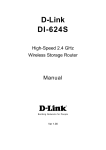
Neptune Serial
E-POS PC
Neptune 1370 / 1478
Super Compact PC
User's Manual
Manual Revision 1.0 Feb, 2004
Please Read the Manual First.
CHAPTER 0
SAFETY INSTRUCTIONS & USER’S NOTICE
Electrical safety
1. To prevent electrical shock hazard, disconnect the power cable from the electrical outlet
before relocating the system.
2. When adding or removing devices to or from the system, please ensure all device power
cords are unplugged before the signal cables are connected.
3. Make sure the voltage of the power source conforms within the permitted range before
connecting the equipment to the power outlet. If you are not sure of the electricity
voltage that you are using, contact your local electricity company.
4. Place the power cord in such a way that it cannot stepped on. Do not place anything
over the power cord.
5. Always unplug the power cord before inserting any add-on card module.
6. Never pour any liquid into the opening as this could cause damage or electrical shock.
7. If the power supply is broken, do not try to fix it by yourself. Contact a qualified service
technician or your retailer.
Operation safety
1. Before installing any device into the system, carefully read all documents that come with
the package.
2. Keep this User’s Manual for future reference.
3. Keep this equipment away from humidity and dust.
4. Place the equipment on a steady flat surface before setting it up.
5. If any of the following situations arise, have the equipment checked by qualified service
technician:
The power cord or plug is damaged
Liquid has penetrated into the equipment
The equipment has been exposed to moisture
The equipment is not working well or does not work as described in the
User’s Manual
The equipment has been dropped and damaged
The equipment has obvious signs of breakage
6. The openings on the housing are for air ventilation and to protect the equipment from
overheating. DO NOT COVER THESE OPENINGS.
7. DO NOT LEAVE THIS EQUIPMENT IN A NON-AIRCONDITIONED ENVIRONMENT
WHERE THE STORAGE TEMPERATURE MAY GO ABOVE 60ºC (140ºF) AS THIS
CAN DAMAGE THE EQUIPMENT.
8. All cautions and warnings on the equipment should be noted.
CAUTION
The technical descriptions and specifications of the product are subject to
change without notice.
For safety reasons, gloves should be worn when assembling the product.
There is a danger of explosion if the battery is incorrectly replaced. Replace
only with the same or equivalent type of battery recommended by the
manufacturer. Dispose used batteries according to the manufacturer’s
instructions.
2
NOTICES
Federal Communications Commission Statement (FCC Statement)
This device complies with FCC Rules Part 15. Operation is subject to the following two
conditions:
This device may not cause harmful interference.
This device must accept any interference received including interference that
may cause undesirable operation.
This equipment has been tested and found to comply within the limits of a Class A digital device,
pursuant to Part 15 of the FCC Rules. These limits are designed to provide reasonable
protection against harmful interference in a residential installation. This equipment generates,
uses and can radiate radio frequency energy and, if not installed and used in accordance with
the manufacturer’s instructions, may cause harmful interference to radio communications.
However, there is no guarantee that interference will not occur in a particular installation. If this
equipment does cause harmful interference to radio or television reception, which can be
determined by switching the equipment on and off, the user is encouraged to try to correct the
interference by one or more of the following measures:
Reorient or relocate the interference receiving antenna.
Increase the distance of separation between the equipment and interference
receiver.
Connect the equipment to a power outlet on a circuit different from that to which
the interference receiver is connected.
Consult the dealer or an experienced radio/TV technician for help.
WARNING!!
The use of shielded cables for connection of the monitor to the graphics card is
required to assure compliance with FCC regulations. Changes or modifications to
this unit not expressly approved by the party responsible for compliance could void
the user’s authority to operate this equipment.
Note
Changes or modifications not expressly approved by the party responsible for compliance could
void the user’s authority to operate the equipment.
3
USER’S NOTICE
No part of this manual, including the products and software described in it, may be reproduced,
transmitted, transcribed, stored in a retrieval system, or translated into any language in any form or by
any means, except documentation kept by the purchaser for backup purposes, without the express
written permission of the distributor (original supplier).
The distributor (original supplier) provides this manual “AS IT IS” without warranty of any kind,
expressed or implied, including but not limited to the implied warranties or conditions of
merchantability or fitness for a particular purpose. In no event shall the distributor (original supplier),
its directors, officers, employees or agents be liable for any indirect, special, incidental, or
consequential damages (including damages for loss of profits, loss of business, loss of use or data,
interruption of business and the like), even if the distributor (original supplier) has been advised of the
possibility of such damages arising from any defect or error in this manual or product.
Specifications and information contained in this manual are provided for informational use only, and
are subject to change or update at any time without notice, and should not be construed as a
commitment by the distributor (original supplier). The distributor (original supplier) assumes no
responsibility or liability for any errors or inaccuracies that may appear in this manual, including the
products and software described in it.
4
TABLE OF CONTENTS
SAFETY INSTRUCTIONS & USER’S NOTICE
Safety Instruction
User’s Notice
Table of Contents
CHAPTER 1
Page 2
Page 4
Page 5
INTRODUCTION & KEY FEATURES
1.1
1.2
1.3
1.4
1.5
1.6
CHAPTER 2
Introduction
The System Unit Chassis
Pre-Install Notes
The Front Panel Composition
Rear Panel Composition
System Internal Composition
Page 6
Page 6
Page 7
Page 8
Page 8
Page 9
UPGRADES
2.1
2.2
2.3
2.4
2.5
2.6
2.7
2.8
Removing the Cover
Installing Add-On Cards
Installing Hard Disk Drive
Memory Configuration
Installing Serial and Parallel Port Devices
Install DC of LCD and POS Printer output
Installing Cash Drawer
Installing Serial ATA Hard Disk Drive
Page 10
Page 10
Page 11
Page 11
Page 11
Page 11
Page 12
Page 12
Neptune 1478 Specifications
Page 13
Neptune 1370 Specifications
Page 14
Power Supply Specifications
Page 15
FAQ
Page 17
Troubleshooting
Page 18
5
CHAPTER 1
INTRODUCTION & SYSTEM CONFIGURATION
1.1 Introduction
Congratulations on the purchase of your Neptune E-POS PC!
You are now the owner of a state-of-the-art Neptune E-POS PC, the PC that offers enhanced features,
speed and performance, and the PC that is unrivaled by other conventional PCs.
1.2 The System Unit Chassis:
The following information will help you to familiarize with the arrangements of the Neptune E-POS PC.
When you open the package, you will find the items as illustrated in the pictures below:
Neptune 1370 or 1478 E-POS PC
AC Power Cord
Accessory Package
-User’s Manual
-Driver CD
-Front Cover Key
This diagram shows the total content of the box. In the side compartments of each box you will find
the power cord, and in the center, you will find the system unit containing a 3.5-inch floppy disk, HDD
(optional), and an internal CD-ROM (option) drive.
6
1.3 Pre-Installation Notes
Before you start operating your Neptune 1370 / 1478 E-POS PC, please read the following notes
carefully. Thank you for your attention.
Please Note
a. Neptune E-POS PC serial ports: the default setting of COM1 IRQ setting is 4, COM2 IRQ
setting is 3, COM3 IRQ setting is 5, and COM4 IRQ setting is 10.
b. The thermal pad on CPU can be easily damaged if CPU is being frequently removed and
replaced. If the thermal pad is damaged due to the above reason, please contact your
supplier/distributor for replacement of the thermal pad.
c. If you need to replace the HDD, please arrange the cables in the original fashion.
d. For reasons of installation and compatibility, you are suggested to use the DDR RAM Module
from the original manufacturer.
e. The +5V/+12V external DC output for the 9th pin of each COM port should be less than 0.5 A.
f. For updated VGA/LAN drivers, please contact your supplier/distributor.
g. The USB device connector of Hot Swap: please do not plug or unplug any connector when
the system’s power is “on”.
h. You have the alternative of using either the front audio or the rear audio connector to play
sound.
Limitations
Output Voltage Connector
th
9 PIN of COM1
9th PIN of COM2
9th PIN of COM3
9th PIN of COM4
DC 24V for POS Printer
DC 12V for LCD Monitor
Nominal
5V / 0.5A, 12V / 0.5A
5V / 0.5A, 12V / 0.5A
5V / 0.5A, 12V / 0.5A
5V / 0.5A, 12V / 0.5A
1.5A
2.0A
Max Current
5V / 0.7A, 12V / 0.6A
5V / 0.7A, 12V / 0.6A
5V / 0.7A, 12V / 0.6A
5V / 0.7A, 12V / 0.6A
2.0A
3.0A
Suggestions
We strongly recommend you to use the following add-on devices if you need to expand the
functions of Neptune E-POS PC.
Add-on card type
LAN
Modem Card
Wireless LAN
RAID Card
CF Card
Disk On Module
2nd VGA PCI Card
PCMCIA PCI slot Card
Brand
Reltek
SIS
D-Link
3 COM
Motorola
Conexant (Rockwell)
D-Link
D-Link
Promise
PQI
PQI
Model No.
RTL8139C / D
SIS900
DFE-530TX
3C905C
SM56
MD-56KUR4
DWL-520+
DWL-G520+
Fast TRAK 100 TX2
32MB ~ 512MB
16MB ~ 512MB
SMI722
Card bus
Remark
10/100 Base T
10/100 Base T
10/100 Base T
10/100 Base T
56K
56K
IEEE 802.11b
IEEE 802.11g
RAID 0 / 1 / 0+1
Industry level
IDE ATA 40 PIN
16/32 bit, 3.3V/5V
Note:
Maximum Dimensions of PCI Add-On Card are 110 mm (Height) x 140 mm (Length).
7
1.4 The Front Panel Composition
LED
Indicator
1.5 Rear Panel Composition
8
1.6 System Internal Composition
9
CHAPTER 2
UPGRADES
Your warranty remains in effect only if all internal settings are done by the authorized dealer or
technicians. This section is intended only for users who wish to perform adjustments by themselves
and thereby void the warranty.
At any time, you can add (or remove) hardware to (or from) your Neptune E-POS PC and modify its
capabilities. The information in this chapter will provide instruction on how to open the chassis.
2.1 Removing the Cover
WARNING: Make sure that the power of your system, as well as any peripheral devices, has been
turned off before removing the chassis.
Tools
You will need a few simple tools to disassemble a Neptune E-POS PC.
* A screwdriver
* Labeling material (tape, paper, pen)
* Cups or trays to temporarily store various screws
2.2 Installing Add-On Cards
In the future, you may need to install one or more Add-On Cards. The Neptune E-POS PC includes 2
PCI slots for the addition of peripherals.
WARNING: Because Neptune E-POS PC has the space-saving design, the format of add-on cards
that can be installed is restricted to the following –
Maximum PCI card dimensions: 110 mm (Height) x 140mm (Length).
Please make sure that the add-on card that you are going to install in the Neptune E-POS PC system
conforms to these requirements.
After physically installing the add-on card, configure the card by adjusting the software settings.
1. Turn on the system and change the BIOS settings, if necessary. See Chapter 4 for
more information on BIOS setup.
2. Assign an IRQ to the card. Refer to the table below.
3. Install the software driver for the add-on card.
IRQ
0
1
2
3 *
4 *
5 *
6
7 *
8
9 *
10 *
11 *
12 *
13
14 *
15 *
Priority
1
2
N/A
11
12
13
14
15
3
4
5
6
7
8
9
10
Standard Function
System Timer
Keyboard Controller
Programmable Interrupt
Communications Port (COM2)
Communications Port (COM1)
Communications Port (COM3)
Floppy Disk Controller
Printer Port (LPT1)
System CMOS/Real Time Clock
ACPI Mode when used
Communications Port (COM4)
IRQ Holder for PCI steering
PS/2 Compatible Mouse Port
Numeric Data Processor
Primary IDE Channel
Secondary IDE Channel
*These IRQs are usually available for ISA or PCI devices.
10
2.3 Installing a Hard Disk Drive
WARNING: If you buy a Neptune E-POS PC without a Hard Disk Drive and you would like to upgrade
it later, please consult with your dealer.
2.4 Memory Configuration
The Neptune E-POS PC allows you to increase the system’s main memory via onboard DIMM
Sockets. The Neptune E-POS PC supports two banks of 128/256/512/1024 MB DIMM Modules.
CPU FSB
DDR DIMM Type
Memory Frequency
800 MHz
PC3200 / PC2700* / PC2100
400 / 333* / 266 MHz
533 MHz
PC2700 / PC2100
333 / 266 MHz
400 MHz
PC2100
266 MHz
*Note
1. When using 800MHz CPU FSB, PC270 DDR DIMM may run only
at 320MHz (not 333MHz) due to chipset limitation.
2. If you wish to upgrade the memory, please consult with your dealer.
2.5 Installing Serial and Parallel Port Devices
1. Please confirm the serial and parallel ports in sequence from above Figure.
2. If you wish to support +5V / +12V output from 9th PIN of serial ports, please consult with your
dealer.
2.6 Installing DC of LCD and POS Printer output
1. The voltage output of the 2.5mm jack is +12V for LCD Monitor.
2. The voltage output of the Hosiden jack is +24V for POS Printer.
Note
1. If the 2.5mm jack is used to power an LCD, extra caution needs
to be taken in the event when the cable comes loose. If the cable
becomes detached, either on the Neptune E-POS PC end or the
LCD end, first switch off the monitor using the power button on
the front of the LCD, and then re-attach the cable. If this is not
carried out correctly and the LCD is left on while trying to reconnect the cable, there is a risk of blowing the fuse or even
damage the Neptune E-POS PC.
2. Ensure that the POS Printer is switched off before you plug in or
remove the Hosiden connector to/from the Neptune E-POS PC.
Hosiden Pin Number
1
2
3
SHELL
Signal Name
+24V
Ground
NC
Frame Ground
11
+12
GN
2.7 Installing a Cash Drawer
Pin Number
1
2
3
4
5
6
Signal Name
Frame GND
Drawer kick-out drive signal
Drawer open / close signal
+24V / +12V
NC
Signal GND
Direction
—
Output
Input
+24V Default
Output
—
Note: +24V is outputted through pin 4 when the power is turned on. However, pin 4 must be used
only for cash drawer.
2.8 Installing the Serial ATA Hard Disk Drive (Neptune 1478 only)
These next generation connectors support the thin Serial ATA cables for serial ATA hard disks. The
current Serial ATA interface allows a data transfer rate of up to 150 MB/s, faster than the standard
parallel ATA with 133 MB/s (Ultra ATA/133).
Parallel ATA and Serial ATA device configurations
Following are the Parallel ATA and Serial ATA device configurations supported by Intel ICH5
specifications.
Native OS are Windows 2000/XP. ICH5 supports a maximum of six devices using these OS. Legacy
OS are MS-DOS, Windows 98/Me/NT4.0. ICH5 supports a maximum of four devices using these OS.
P-ATA
Primary
Secondary
(2 devices)
(2 devices)
Operating System
S-ATA
Port0
Port1
(1 devices)
(1 devices)
ν
ν
ν
ν
Configuration A
ν
—
Configuration B
—
ν
ν
Configuration C
ν
ν
ν
ν
ν
—
—
Windows 2000/XP
Windows 98/Me/NT4.0
Legend:
ν
—
Supported
Disabled
Required IDE Configuration settings in BIOS
Refer to the following table for the appropriate BIOS settings of the above P-ATA and S-ATA device
configurations.
Windows 98/Me/NT4.0
B
BIOS Item
Windows
2000/XP
A
Onboard IDE Operation Mode
Enhanced Mode
Compatible Mode
Compatible Mode
Compatible Mode
Enhanced Mode Support On
S-ATA
—
—
—
IDE Port Settings
—
Primary P-ATA+S-ATA Sec. P-ATA+S-ATA
12
C
P-ATA Ports Only
Neptune 1478 E-POS PC Socket 478 Specifications
Item
Description
CPU
Supports Intel P4 up to 3.2GHz / Celeron up to 2.8GHz Socket 478 CPU
FSB
Main Memory
System Chipset
BIOS
400 / 533 / 800MHz
184-Pin DDR RAM * 2 up to 2GB. (DDR 266 / 333 / 400)
North Bridge: Intel 865GV, South Bridge: Intel ICH5.
Enhanced ACPI 2.0 / PnP / APM / DMI / ESCD / PCI bus 2.2 / On Now / DRAM ECC Quick
Boot/ HW Monitor (LDCM) / I-O Pre-set IRQ / Spread Spectrum / PC98 compliant
One LPT port (SPP/EPP/ ECP); IRQ and address selector by BIOS setup
COM1, COM2, COM3, COM4 IRQ selector by BIOS setup (jumper less) and +5v or +12V
output on pin 9th by jumper selector
Four USB 2.0 ports that support Windows 98 / 2000 / XP
Standard 1.44MB FDD x 1
1.44MB 3.5" FDD x 1
On board PCI Bus Master IDE1/2 controller with Windows utility; supports Ultra DMA66/100
Intel 865GV AGP; shared memory from 1MB up to 32MB
-Supports AGP 3.0 (8X) VGA controller
-Direct X, VPE, MPEG4
-Supports DVD Video Accelerator
-PC98 compliant
-Supports 3D/2D Accelerator
-Supports VESA DPMS VGA monitor
-NT4.0/5.0, Windows95/98/2000 utility
-APM/ACPI 2.0
-ACPI/NT4.0/5.0 (NDIS 5) (10/100 Mbps Auto)
-Supports Remote Boot ROM for Windows NT 4.0/5.0, 2000, XP and Linux
-NT4.0/Win95/98/2000/XP Utility
-PC98 compliant
-Enable or Disable by BIOS setup
AC97 CODEC on board
PS/2 type
PS/2 type
-AC power on/off Trigger button. Reset Button.
-Cover with Key Lock for FDD / CD ROM / CF and Power switch.
-5 LED indicators: Power On/Off, HDD, CF state & LAN state and Suspend Mode LED.
-3.5" FDD Bay * 2 (2.5" IDE HDD Rack with Keylock Ready)
-USB3 / USB4 Connector
-ATA Compact Flash Card Type I/II Socket
-VGA 15-pin DSUB connector
-LAN RJ-45 output connector
-COM 1/2 9-pin DSUB output
-USB1/USB2 connector
-COM 3/4 9-pin DSUB output
-LPT 25-pin DSUB connector
-PS/2 keyboard & mouse connector
-Audio Line in / Line out / MIC-in
-DC12V Power outlet for LCD Display Source
-DC 24V Power outlet for POS Printer (Hosiden 3 PIN)
-2 * Cash Drawer Kick-Out Driver with EPSON RJ-12 Connector (12V or 24V Solenoid Type)
-One low noise 60mm FAN (two ball) for CPU Heat-Sink and Air Tunnel
-One low noise 60mm FAN (two ball) for Power Supply
Two free PCI slots riser card
ATX 250W Internal Power Supply (UL, CSA, VDE, EMI meets FCC “B”) with Power Switch
AC 90V to 264V, 47Hz / 63Hz
Two U type Foot Stands Per Set (Option)
11.6” (W) x 13.5” (D) x 3.7” (H) (295 x 345 x 95 mm)
Each packing set: 34 x 34 x 17cm NW/GW: 8.5kg/10.5kg
DOS/OS2 V2.1 /XENIX V2.3.2/UNIX V3.2/NOVELL/ WIN 3.1/95/98/2000/XP/NT4.0
0ºC to 40ºC (without HDD up to 50ºC)
-25ºC to 70ºC
Parallel Port
Serial Port
USB
Floppy Disk Port
FDD
Enhance PCI IDE
AGP 3D Graphics Port
PCI LAN Port
Audio Port
PS/2 Keyboard Port
PS/2 Mouse Port
Front Panel
Rear Panel
Thermal Solution
Expansion Slots
AC Power Supply
AC Power Source
Vertical Stand
Case Dimension
Export Packing
S/W Compatibility
Operation Temperature
Storage Temperature
OPTIONS
PCI Modem Card
PCI Wireless LAN Card
PCI ATA RAID Card
IDE2 CD-ROM
Disk On Module Port
2nd VGA PCI card
Win98/2000/XP utility (33.6 or 56K) supports PCI2.2 / ACPI2.0.
Win98/2000/XP utility supports IEEE 802.11b or 802.11g
Win98/2000/XP utility supports RAID 0 / 1 / 0+1
On board PCI Bus Master IDE1/2 controller with Win98/2000/XP utility; Ultra DMA/33
16 to 512 MB ATA IDE type DOM socket
2nd VGA output
Specifications are subject to change without notice.
13
Neptune 1370 E-POS PC Socket 370 Specifications
Item
Description
CPU
Supports Intel PIII / Celeron up to 1.26GHz / 1.4GHz and VIA C3 up to 1GHz or more CPUs
FSB
Main Memory
System Chipset
BIOS
66 / 100 / 133MHz
184-Pin DDR RAM * 2 up to 2GB. (DDR 266)
North Bridge: VIA VT8623 (CLE266), South Bridge: VT8235
Enhanced ACPI 1.0 / PnP / APM / DMI / ESCD / PCI bus 2.2 / On Now / DRAM ECC Quick
Boot/ HW Monitor (LDCM) / I-O Pre-set IRQ / Spread Spectrum / PC98 compliant
One LPT port (SPP/EPP/ ECP); IRQ and address selector by BIOS setup
COM1, COM2, COM3, COM4 IRQ selector by BIOS setup (jumper less) and +5v or +12V
output on pin 9th by jumper selector
Four USB 2.0 ports that support Windows 98 / 2000 / XP
Standard 1.44MB FDD x 1
1.44MB 3.5" FDD x 1
On board PCI Bus Master IDE1/2 controller with Windows utility; supports Ultra DMA66/100
VT8623 AGP; shared memory from 1MB up to 64MB
-Supports AGP 2.0 (4X) VGA controller
-Direct X, VPE, MPEG2
-Supports DVD Video Accelerator
-PC98 compliant
-Supports 3D/2D Accelerator
-Supports VESA DPMS VGA monitor
-NT4.0/5.0, Windows95/98/2000 utility
-APM/ACPI 1.0
-ACPI/NT4.0/5.0 (NDIS 5) (10/100 Mbps Auto)
-Supports Remote Boot ROM for Windows NT 4.0/5.0, 2000, XP and Linux
-NT4.0/Win95/98/2000/XP Utility
-PC98 compliant
-Enable or Disable by BIOS setup
AC97 CODEC on board
PS/2 type
PS/2 type
-AC power on/off Trigger button. Reset Button.
-Cover with Key Lock for FDD / CD ROM / CF and Power switch.
-5 LED indicators: Power On/Off, HDD, CF state & LAN state and Suspend Mode LED.
-3.5" FDD Bay * 2 (2.5" IDE HDD Rack with Keylock Ready)
-USB3 / USB4 Connector
-ATA Compact Flash Card Type I/II Socket
-VGA 15-pin DSUB connector
-LAN RJ-45 output connector
-COM 1/2 9-pin DSUB output
-USB1/USB2 connector
-COM 3/4 9-pin DSUB output
-LPT 25-pin DSUB connector
-PS/2 keyboard & mouse connector
-Audio Line in / Line out / MIC-in
-DC12V Power outlet for LCD Display Source
-DC 24V Power outlet for POS Printer (Hosiden 3 PIN)
-2 * Cash Drawer Kick-Out Driver with RJ-12 Connector (12V or 24V Solenoid Type)
-One low noise 60mm FAN (two ball) for CPU Heat-Sink and Air Tunnel
-One low noise 60mm FAN (two ball) for Power Supply
Two free PCI slots riser card
ATX 250W Internal Power Supply (UL, CSA, VDE, EMI meets FCC “B”) with Power Switch
AC 90V to 264V, 47Hz / 63Hz
Two U type Foot Stands Per Set (Option)
11.6” (W) x 13.5” (D) x 3.7” (H) (295 x 345 x 95 mm)
Each set packing: 34 x 34 x 17cm NW/GW: 8.5kg/10.5kg
DOS/OS2 V2.1 /XENIX V2.3.2/UNIX V3.2/NOVELL/ WIN 3.1/95/98/2000/XP/NT4.0
0ºC to 40ºC (without HDD up to 50ºC)
-25ºC to 70ºC
Parallel Port
Serial Port
USB
Floppy Disk Port
FDD
Enhance PCI IDE
AGP 3D Graphics Port
PCI LAN Port
Audio Port
PS/2 Keyboard Port
PS/2 Mouse Port
Front Panel
Rear Panel
Thermal Solution
Expansion Slots
AC Power Supply
AC Power Source
Vertical Stand
Case Dimension
Export Packing
S/W Compatibility
Operation Temperature
Storage Temperature
OPTIONS
PCI Modem Card
PCI Wireless LAN Card
PCI ATA RAID Card
IDE2 CD-ROM
Disk On Module Port
Dual VGA out card
Win98/2000/XP utility (33.6 or 56K) supports PCI2.2 / ACPI2.0.
Win98/2000/XP utility supports IEEE 802.11b or 802.11g
Win98/2000/XP utility supports RAID 0 / 1 / 0+1
On board PCI Bus Master IDE1/2 controller with Win98/2000/XP utility; Ultra DMA/33
16 to 512 MB ATA IDE type DOM socket
2nd VGA output
Specifications are subject to change without notice.
14
Power Supply Specifications
Input Regulations
Input Voltage Range (Auto Switching)
Min
Nom
Max
Voltage 110V
90V
100V ~ 127V
140V
Voltage 220V
180V
200V ~ 240V
264V
Input Frequency Range
47 Hz to 63Hz
6A maximum at 115VAC
Maximum Input AC Current
3A maximum at 230VAC
Inrush Current
90A maximum at 115VAC
Efficiency
70% min. at nominal input, maximum load.
Output Regulations
Output
Voltage
Range
Min
Nominal
Max
Units
+5v
±5%
+4.75
+5.00
+5.25
Volts
+12v
±5%
+11.40
+12.00
+12.60
Volts
-12v
±10%
-10.80
-12.00
-13.20
Volts
-5v
±5%
-4.75
-5.00
-5.25
Volts
+3.3v
±5%
+3.14
+3.30
+3.47
Volts
+5vsb
±5%
+4.75
+5.00
+5.25
Volts
Note:
1. The above voltage range should also include ripple and noise.
2. The output voltage should be measured at the terminals of output connector.
DC Load Requirements
Output Voltage
Min
Current
Max
Current
Peak
Current
+5V
1.5
19
+12V
2.0
16
-12V
0.0
0.8
AMPS
-5V
0.0
0.1
AMPS
+3.3V
1.0
18
AMPS
+5Vsb
0.0
2.0
AMPS
Units
AMPS
24
AMPS
Note:
1. The maximum continuous total DC output power shall not exceed 250 Watts.
2. The maximum continuous combined load on +5V and +3.3V outputs shall not
exceed 105W(22A)
3. The maximum continuous combined load on +5V, +3.3V and +12V outputs shall not
exceed 230 Watts.
4. Peak currents may last up to 0.5 seconds with not more then one occurrence per
minute.
15
Over Voltage Protection
When the DC outputs (+5V, +12V, and +3.3V) have over voltage condition, the power supply shall
provide latch mode over voltage protection.
DC output
Max
Unit
+12V
15.6
V
+5V
7.0
V
+3.3V
4.3
V
Short Circuit Protection
A short circuit placed to ground shall cause no damage and shall be shutdown. (The contact
resistance is 0.05 ohm when the outputs short circuit.)
Protection Reset
When the power supply latches into shutdown condition due to a fault on an output (OPP, OVP,
LVP), the protection shall reset after the fault has been removed, use remote on/off control or
recycle the AC power again for a typical of 3 seconds.
Over Shoot
Any output overshoot at turn on shall be less than 10% of the nominal output value (with resistive
load) as described in sec. Input Regulations.
Over Power Protection
At 115/230 VAC input the power supply will shut down all DC outputs within 105% to 140% of full
load.
16
FAQ
Below is a collection of frequently asked questions.
Question 1: I cannot see some options that appeared in the previous BIOS settings after updating
BIOS. Why?
Answer: Some advanced options are hidden in the new BIOS version. Please press Ctrl and F1 keys
after entering the BIOS menu to see these options.
Question 2: Why is the light on the keyboard / optical mouse still on after computer shuts down?
Answer: In some boards, a small amount of electricity is kept on standby after the computer shuts
down, which is why the light is still on.
Question 3: How do I clear CMOS?
Answer: If your board has a Clear CMOS jumper, please refer to the Clear CMOS steps in the
manual. If your board does not have such jumper, you can take off the on-board battery to leak
voltage and to clear CMOS. Please refer to the steps below:
Steps:
1. Turn off power.
2. Switch off the power from ATX PSU.
3. Take out the battery gently and put it aside for about 10 minutes (or you can use a metal
object to connect the positive and negative pins in the battery holder to short-circuit for one
minute).
4. Re-insert battery to the battery holder.
5. Switch on the power again.
6. Press Del to enter BIOS and Load Optimized Defaults.
7. Save changes and reboot the system.
Question 4: Why does system seem unstable after updating BIOS?
Answer: Please remember to load Optimized Defaults (or load SETUP Default) after flashing BIOS.
However, if the system still remains unstable, please clear CMOS to solve the problem.
Question 5: Why do I still get a weak sound even if the speaker is turned to the maximum volume?
Answer: Please make sure the speaker you are using is equipped with an internal amplifier. If not,
please change another speaker with power/amplifier and try again.
Question 6: How to set the BIOS in order to boot-up from SATA HDDs by either ATA mode?
Answer: Please set the BIOS as follow:
1. Advanced BIOS features SATA/RAID/SCSI boot order: “SATA”
2. Advanced BIOS features First boot device: “SCSI”
3. Integrated Peripherals Onboard H/W Serial ATA: “enable”
Then it depends on the SATA mode that you need to set “BASE” to normal ATA mode in the item
named Serial ATA function.
Question 7: How to set the BIOS to boot-up from the IDE/SCSI/RAID card?
Answer: Please set the BIOS as follows:
1. Advanced BIOS features SATA/RAID/SCSI boot order: “SCSI”
2. Advanced BIOS features First boot device: “SCSI”
Then it depends on the mode (RAID or ATA) that you need to set in RAID/SCSI BIOS.
17
Troubleshooting
Please make sure all jumper settings (such as CPU system
bus speed, frequency ratio, voltage, etc.) are set properly.
Make sure
the jumper
settings are
correct.
Check if the CPU cooling fan attached to the CPU is
working properly, and if the CPU cooling fan’s power is
connected properly.
Plug the CPU
cooling fan’s
power into the
CPU fan
connector. Plug
into the AC
power
t
Check if the memory module has been installed
properly into the DIMM slot.
18
If you are still unable to solve your problem after having followed the above procedures, please
contact your local retailer or national distributor for help.
19