1
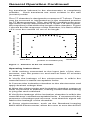
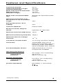
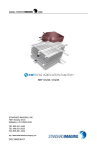
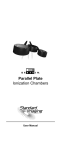
A101 CT
Ionization Chamber
REF 92680
R
User Manual
WWW.
.COM
A101 CT
Ionization Chamber
REF 92680
STANDARD IMAGING INC.
7601 Murphy Drive
Middleton, WI 53562-2532
Feb / 2005 ©2005 Standard Imaging Inc.
DOC #80362-03
TEL 800.261.4446
TEL 608.831.0025
FAX 608.831.2202
General Precautions
Warnings and Cautions alert users to dangerous conditions that can occur if instructions in the manual are
not obeyed. Warnings are conditions that can cause
injury to the operator, while Cautions can cause damage to the equipment.
!
WARNING:
Electrical shock hazard when connected to 300
V bias supply.
!
WARNING:
Exradin Ion Chambers are intended for quality
assurance and calibration measurements. They
are not intended to be connected to a patient for
real-time dosimetry measurements.
!
CAUTION:
Proper use of this device depends on careful
reading of all instructions and labels.
!
CAUTION:
Do not drop, mishandle, or disassemble unit
since it may result in a change of calibration
factor, or damage to thin-walled Thimble tip.
Refer all servicing to qualified individuals.
!
CAUTION:
Do not sharply bend triax cable. Damage to the
cable may result in high leakage currents.
4
Table of Contents
PAGE
4
5
7
8
11
12
13
14
General Precautions
General Operation
Parts and Accessories
Features and Specifications
Service Notes
Service Policy
Customer Responsibility
Warranty
7601 MURPHY DRIVE
MIDDLETON, WI 53562-2532 USA
WWW.STANDARDIMAGING.COM
General Operation
Exradin chambers are attached to a 1.5 m length of lownoise flexible triaxial cable that is terminated by a triaxial or
coaxial connector. The collector of the chamber is common
with the center wire of the cable and the center contact of the
connector. The guard is common with the inner cable braid
and the middle connector contact of triaxial connectors, and
the connector body of coaxial connectors. The shell (outer
electrode), usually ground, is common with the outer braid
of the cable and the connector body in the case of triaxial
connectors and the pigtail extending out the rear of coaxial
connectors.
The design of Exradin chambers requires that the collector
and guard operate at essentially the same potential. The
polarizing potential, supplied by an electrometer, is applied
between the shell and the guard. Either polarity may be
applied to the shell and either the shell or guard may be
grounded. Safety and other considerations recommend
grounding the shell, which then requires an electrometer
with a floating input.
All Exradin chambers can support 1000 V between shell and
guard. However, depending on the particular circumstance
and radiation intensity, as little as 90 V may yield essentially
100% charge collection.
Because Exradin ionization chambers do not exhibit voltage soakage phenomena, readings of ionization current
may be made immediately after application of the polarizing potential. However, it is good practice to pause a
minute or two after changing the potential to allow switch-
5
General Operation Continued
ing transients induced in the electrometer to completely
subside. Such transients are most evident in the rate
(current) mode.
The CT chamber is designed to measure CT slices. These
may be summed or integrated as is the standard practice
for CT Measurements. Thus, the MSAD (multiple scan average dose) can be determined as is usual. For this reason,
the response is flat within the length of the chamber. Figure
1 shows the flat response of the chamber; it is flat to within
+3% over the central 10 cm of its length.
reading normalized to central value
1.0
0.8
0.6
0.4
0.2
0.0
-10
-8
Stem End
-6
-4
-2
0
2
4
position on chamber (cm)
6
8
10
Distal End
Figure 1: Flatness of the CT chamber
Operating Instructions
1. With nothing connected to the input jack of the electrometer, turn the power on and wait at least 15 minutes
for warm up.
2. Verify the leakage of the electrometer is within the
manufacturer’s stated acceptable limits.
3. Connect the ionization chamber to the electrometer and
apply desired voltage bias.
4. Allow the electrometer and ionization chamber system at
least 10 minutes to stabilize, making certain that all cabling
is lying flat and unkinked.
5. Verify the leakage of the ionization chamber is within the
manufacturer’s stated acceptable limits. If measured in the
presence of background sources, note that this signal will
add to the leakage of the chamber.
6. Some electrometers, such as the Standard Imaging
MAX-4000 Electrometer, allow the user to zero the device
6
General Operation Continued
at any time. If desired, perform this system zeroing now.
7. Check the system leakage. Take a reading without exposing the chamber to radiation. This reading should be
less than 0.1% of the final signal expected. If it is not, the
leakage should be subtracted from the signal.
8. Measure atmospheric temperature and pressure.
9. Insert the CT chamber and take at least 3 measurements.
Generally, the measurements should not be moving in only
one direction (i.e. three readings that continue to drop and
hence may not yet be stabilized). If a current measurement
is done, allow sufficient time for value to stabilize.
10. Analyze the data taking into account the average
of the readings, system leakage, temperature/pressure
corrections, calibration factors and any other appropriate
corrections to be made. Keep in mind that the calibration
factor consists of the electrometer calibration and the ionization chamber calibration factor.
11. When all measurements are completed, set bias voltage to 0 VDC, turn off the electrometer and disconnect the
ionization chamber.
Parts and Accessories
REF
Description
72170
A101 Acrylic Adapter Sleeve
1.3 mm, PMMA
LEMO Connector in place of
Triax BNC Plug (M/F)
72157
7
Features and Specifications
Collecting Volume:
Collecting Volume Length:
Collector Diameter:
Body Tube Outside Diameter:
Wall Thickness:
Chamber Length:
4.6 cc
10.0 cm
2.4 mm
10.0 mm
1.0 mm
164.3 mm
Body Tube and Guard Material:
Shonka air-equivalent C552
plastic
Response Uniformity over
the central 10 cm of chamber
length:
±3%
Energy Response, 80 to
150kVp:
±4%
Collector Material:
Carbon Fiber
Electrical Power Requirements:
Operates at +300 VDC
Nominal Collection Efficiency: 100%
Maximum Polarizing Potential: 1000 V
Nominal Inherent Leakage
Currents:
10-15 A
Low-Noise Triaxial Cable:
1.5 m long; 50 ohms; 29 pf/ft
Connector:
Triaxial BNC Plug (2-Lug
Male) and protective cap connected by chain (standard);
others available upon request
Included Adapter Sleeve:
Wall Thickness of 1.3 mm;
Constructed of PMMA
Operating Parameters
Humidity:
Temperature:
Pressure:
20 to 80%, non-condensing
10 to 40o C
680 to 770 mm Hg
Storage Parameters
Humidity:
Temperature:
Pressure:
0 to 95%, non-condensing
-15 to 50o C
600 to 800 mm Hg
Product Standards:
IEC 60601-11, IEC 616741
1
Designed to Meet
8
Notes
9
Notes
10
Service Notes
External Marks
The Exradin A101 CT Chamber is provided with (3) external
groove marks on the chamber body, signifying important
locations of the collecting volume. The middle groove
represents the center of the axial length of the collecting
volume. The two outer-most grooves represent the termination of the collecting volume, each 5 cm away from the
central groove. Within these two outer-most grooves is the
collecting volume that is rated with a flatness response of
±3%, and is 10.0 cm in length.
Adapter Sleeve
The Adapter Sleeve for the CT Chamber is constructed
of acrylic (PMMA). The Adapter Sleeve has an outer diameter of 12.7 mm which will fit into most commercially
available CT Phantoms. Simply slide the Sleeve over the
CT Chamber until the Sleeve bottoms on the shoulder of
the CT Chamber, and insert the CT Chamber with sleeve
into the CT Phantom.
Venting
The CT Chamber vents to the ambient via (2) holes located
on the cylindrical body of the chamber proper. When the
acrylic Adapter Sleeve is in position on the chamber body,
there is adequate clearance for the chamber to vent.
Underwater Operation
This chamber is not waterproof. This type of chamber is
typically not used in water.
!
Service and Maintenance
There are no user-serviceable parts within this ionization chamber. Under no circumstance should the
user attempt to repair or disassemble the chamber
and/or connector, as the warranty will become void
and the calibration factor will change. Under normal
use, the chambers should provide years of troublefree service.
If assistance is desired in the proper disposal of this
product (including accessories and components), after
its useful life, please return to Standard Imaging.
11
Service Policy
If service, including recalibration, is required, please contact Standard Imaging’s Customer Service department by
phone or email prior to shipping the product. Standard
Imaging’s Customer Service and Technical Service staff will
attempt to address the product issue via phone or email. If
unable to address the issue, a return material authorization (RMA) number will be issued. With the RMA number,
the product can be returned to Standard Imaging. It is the
responsibility of the customer to properly package, insure
and ship the product, with the RMA number clearly identified on the outside of the package. The customer must
immediately file a claim with their carrier for any shipping
damage or lost shipments. Return shipping and insurance
is to be pre-paid or billed to the customer, and the customer
may request a specific shipper. Items found to be out of
warranty are subject to a minimum service fee of 1 hour
labor (excluding recalibrations) for diagnostic efforts and
require a purchase order (PO) before service is performed.
With concurrence from customer, the product may be replaced if it is unserviceable or if the required service is
cost prohibitive. Products incurring service charges may
be held for payment. Standard Imaging does not provide
loaner products. See the Standard Imaging Warranty and
Customer Responsibility for additional information.
12
Customer Responsibility
This product and its components will perform properly and
reliably only when operated and maintained in accordance
with the instructions contained in this manual and accompanying labels. A defective device should not be used.
Parts which may be broken or missing or are clearly worn,
distorted or contaminated should be replaced immediately
with genuine replacement parts manufactured by or made
available from Standard Imaging Inc.
!
CAUTION: Federal law in the U.S.A. and Canadian law restrict the sale, distribution, or
use of this product to, by, or on the order of a
licensed medical practitioner. The use of this
product should be restricted to the supervision
of a qualified medical physicist. Measurement of
high activity radioactive sources is potentially
hazardous and should be performed by qualified personnel.
Should repair or replacement of this product become
necessary after the warranty period, the customer should
seek advice from Standard Imaging Inc. prior to such repair or replacement. If this product is in need of repair, it
should not be used until all repairs have been made and
the product is functioning properly and ready for use. After
repair, the product may need to be calibrated. The owner
of this product has sole responsibility for any malfunction
resulting from abuse, improper use or maintenance, or
repair by anyone other than Standard Imaging Inc.
The information in this manual is subject to change without
notice. No part of this manual may be copied or reproduced
in any form or by any means without prior written consent
of Standard Imaging Inc.
13
Warranty
Standard Imaging, Inc. sells this product under the warranty herein
set forth. The warranty is extended only to the buyer purchasing
the product directly from Standard Imaging, Inc. or as a new product
from an authorized dealer or distributor of Standard Imaging, Inc.
For a period provided in the table below from the date of original delivery to
the purchaser or a distributor, this Standard Imaging, Inc. product, provided
in the table is warranted against functional defects in design, materials and
workmanship, provided it is properly operated under conditions of normal
use, and that repairs and replacements are made in accordance herewith.
The foregoing warranty shall not apply if the product has been altered,
disassembled or repaired other than by Standard Imaging, Inc. or if the
product has been subject to abuse, misuse, negligence or accident.
Product
Standard Imaging
Ionization Chambers
Standard Imaging Well
Chambers
Standard Imaging
Electrometers
Standard Imaging
Software Products
All Other Standard
Imaging Products
Standard Imaging
Custom Product
Consumables
Serviced Product
Resale Products
ADCL Product
CalibrationADCL
Product Calibration
(Standard Imaging
uses the UW-ADCL
for recalibrations
required under warranty)
Warranty Period
2 years
2 years
2 years
1 year
1 year
90 days
90 days
90 days
As defined by the Original Equipment Manufacturer
0 - 90 days = 100% of ADCL Calibration Costs
91 - 182 days = 75% of ADCL Calibration Costs
183 – 365 days = 50% of ADCL Calibration Costs
366 – 639 days = 25% of ADCL Calibration Costs
(days from date of shipment to customer)
Standard Imaging’s sole and exclusive obligation and the purchaser’s sole
and exclusive remedy under the above warranties are, at Standard Imaging’s option, limited to repairing, replacing free of charge or revising labeling
and manual content on, a product: (1) which contains a defect covered by
the above warranties; (2) which are reported to Standard Imaging, Inc. not
later than seven (7) days after the expiration date of the warranty period in
the table; (3) which are returned to Standard Imaging, Inc. promptly after
discovery of the defect; and (4) which are found to be defective upon examination by Standard Imaging Inc. Transportation related charges, (including,
but not limited to shipping, customs, tariffs, taxes, and brokerage fees) to
Standard Imaging are the buyer’s responsibility. This warranty extends to
every part of the product except consumables (fuses, batteries, or glass
breakage). Standard Imaging, Inc. shall not be otherwise liable for any
damages, including but not limited to, incidental damages, consequential
damages, or special damages. Repaired or replaced products are warranted for the balance of the original warranty period, or at least 90 days.
This warranty is in lieu of all other warranties, express or implied,
whether statutory or otherwise, including any implied warranty of fitness for a particular purpose. In no event shall Standard Imaging,
Inc. be liable for any incidental or consequential damages resulting
from the use, misuse or abuse of the product or caused by any defect,
failure or malfunction of the product, whether a claim of such damages is based upon the warranty, contract, negligence, or otherwise.
This warranty represents the current standard warranty of Standard
Imaging, Inc. Please refer to the labeling or instruction manual of your
Standard Imaging, Inc. product or the Standard Imaging, Inc. web page
for any warranty conditions unique to the product.
14