1
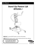
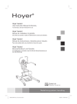
Owner’s Operator and Maintenance Manual
Get-U-Up™ Lift
DEALER: This manual MUST be given to the user of the patient lift.
USER: BEFORE using this patient lift, read this manual and save for future reference.
For more information regarding
Invacare products, parts, and services,
please visit www.invacare.com
WARNING
DO NOT USE THIS PRODUCT OR ANY AVAILABLE OPTIONAL EQUIPMENT
WITHOUT FIRST COMPLETELY READING AND UNDERSTANDING THESE
INSTRUCTIONS AND ANY ADDITIONAL INSTRUCTIONAL MATERIAL
SUCH AS OWNER’S MANUALS, SERVICE MANUALS OR INSTRUCTION
SHEETS SUPPLIED WITH THIS PRODUCT OR OPTIONAL EQUIPMENT. IF
YOU ARE UNABLE TO UNDERSTAND THE WARNINGS, CAUTIONS OR
INSTRUCTIONS, CONTACT A HEALTHCARE PROFESSIONAL, DEALER OR
TECHNICAL PERSONNEL BEFORE ATTEMPTING TO USE THIS EQUIPMENT
- OTHERWISE, INJURY OR DAMAGE MAY OCCUR.
ACCESSORIES WARNING
Invacare products are specifically designed and manufactured for use in conjunction with
Invacare accessories. Accessories designed by other manufacturers have not been tested by
Invacare and are not recommended for use with Invacare products.
SYMBOL LEGEND
"ATTENTION, see instructions for use".
"Date of Manufacture"
2009
CAUTION - Pinch Points, fingers could be pinched.
Device contains Lead Acid batteries.
DO NOT dispose of batteries in
normal household waste. They MUST
be taken to a proper disposal site.
Contact your local waste
management company for
information.
WARNING - When positioning Lift, be aware of the
position of the Swivel Bar and the patient. Injury could
occur.
EMERGENCY Mechanical Lowering Pull UP on EMERGENCY Button.
Push DOWN on Boom.
NOTE: Updated versions of this manual are available on www.invacare.com.
Get-U-Up™ Lift
2
Part No 1148115
TABLE OF CONTENTS
TABLE OF CONTENTS
SPECIAL NOTES ................................................................................................ 5
LABEL LOCATIONS ........................................................................................... 6
TYPICAL PRODUCT PARAMETERS .................................................................... 7
SECTION 1—GENERAL GUIDELINES ................................................................... 8
Weight Limitation ..................................................................................................................................................................8
Assembling the Lift.................................................................................................................................................................8
Using the Sling.........................................................................................................................................................................8
Operating the Lift...................................................................................................................................................................9
Lifting the Patient ...................................................................................................................................................................9
Transferring the Patient........................................................................................................................................................9
Performing Maintenance.......................................................................................................................................................9
SECTION 2—ASSEMBLY.................................................................................... 10
Attach the Mast to the Base Assembly .......................................................................................................................... 10
Attach the Horn to the Mast and Actuator.................................................................................................................. 11
Check for proper hardware alignment .......................................................................................................................... 11
Attaching/Adjusting the Knee Pad................................................................................................................................... 12
Attaching the Base Shifter Handle................................................................................................................................... 12
SECTION 3—OPERATION ................................................................................ 13
Introduction.......................................................................................................................................................................... 13
Operating the Lift................................................................................................................................................................ 14
Opening/Closing the Legs ............................................................................................................................................. 14
Raising/Lowering Model Hydraulic Lifts .................................................................................................................... 15
Adjusting Knee Pad Height ............................................................................................................................................... 15
SECTION 4—LIFTING ....................................................................................... 16
Introduction.......................................................................................................................................................................... 16
Lifting the Patient ................................................................................................................................................................ 17
Moving the Patient .............................................................................................................................................................. 18
SECTION 5—TRANSFERRING .......................................................................... 19
Transferring to a Commode............................................................................................................................................. 20
Transferring to a Wheelchair........................................................................................................................................... 21
Transferring to a Bed ......................................................................................................................................................... 22
SECTION 6—USING LIFT AS A STANDING AID ................................................. 23
Standing Procedure............................................................................................................................................................. 23
SECTION 7—TROUBLESHOOTING .................................................................... 24
Part No 1148115
3
Get-U-Up™ Lift
TABLE OF CONTENTS
TABLE OF CONTENTS
SECTION 8—MAINTENANCE ........................................................................... 25
Maintenance Safety Inspection Checklist....................................................................................................................... 25
Hydraulic Pump.................................................................................................................................................................... 25
Lubricating the Lift .............................................................................................................................................................. 26
Detecting Wear and Damage........................................................................................................................................... 26
Cleaning the Sling and the Lift.......................................................................................................................................... 26
Replacing the Knee Pad ..................................................................................................................................................... 26
LIMITED WARRANTY ..................................................................................... 27
Get-U-Up™ Lift
4
Part No 1148115
SPECIAL NOTES
SPECIAL NOTES
Signal words are used in this manual and apply to hazards or unsafe practices which could result in
personal injury or property damage. Refer to the table below for definitions of the signal words.
SIGNAL WORD
MEANING
DANGER
Danger indicates an imminently hazardous situation which, if not avoided, will result in
death or serious injury.
WARNING
Warning indicates a potentially hazardous situation which, if not avoided, could result in
death or serious injury.
CAUTION
Caution indicates a potentially hazardous situation which, if not avoided, may result in
property damage or minor injury or both.
NOTICE
THE INFORMATION CONTAINED IN THIS DOCUMENT IS SUBJECT TO CHANGE
WITHOUT NOTICE.
Check ALL parts for shipping damage. If shipping damage is noted, DO NOT use. Contact
dealer/carrier for further instruction.
MAINTENANCE
Maintenance MUST be performed ONLY by qualified personnel.
Part No 1148115
5
Get-U-Up™ Lift
LABEL LOCATIONS
LABEL LOCATIONS
OPERATION OF THE PATIENT LIFT
The mast (C) includes the steering handles used to
move and guide the lift. The mast is supported in a
socket in the rear center of the base with casters (A).
For transporting the lift in a vehicle, the mast, boom and
pump assembly may be lifted from the base socket for
convenient storage. Each time the mast is returned to
the socket of the base, care should be used to push the
mast as far as possible down into the socket. Rotate
the mast slightly until it locks in the center position. The
bottom of the mast tube is grooved on either side, and
those grooves seat on tabs in the base socket to
prevent any rotation of the mast during the lift
procedure. Secure the mast to the base by securely
tightening the screw located at the rear of the base.
Refer to the Patient Sling owner’s manual for complete
lifting preparation information.
The horn (D) is made with knobs on both sides and in
the center to accept the sling that supports the patient
during lift.
There are two controls on the pump assembly (F), which
are the pump handle (G) and the control valve (H). With
the control valve closed, the pump handle is moved up
and down with slow strokes of even pressure to raise
the horn. A patient in a sling attached to the horn would
be elevated by this operation. The horn is lowered by
opening the control valve and moving the control valve
away from the pump handle. A safety gate is part of the
hydraulic system that prevents sudden lowering of the
horn regardless of how far the control valve is opened.
Serial
Number
The knee pad (E) can be adjusted for patient support
and comfort. Pull both adjustment pins outward at the
same time to move the knee pad to the desired
position. Make sure adjustment pins are engaged.
D
G
C
H
Serial
Number
F
B
A
E
I
To raise the footplate (I), position the knee pad (E) in the
highest setting. When the footplate is up, the knee pad
can be adjusted to the desired position.
WARNING: For maximum stability and patient
safety, operate this lift with the base legs in
maximum open position and locked when
lifting a patient.
The shifter handle (B) is used to open the legs of the
base for stability before lifting a patient. The base legs
should be locked in the maximum open position at all
times when a patient is on the lift.
To open the base legs, grasp the shifter handle in one
hand, and place the opposite hand on the steering
handle of the mast for balance. Move the handle to
your right to release the lock pin then bring the handle
towards you in a complete half-circle. The lock pin
should insert into a hole in the plate to lock the legs in
full open position and the shifter handle should once
again be vertical. To close the legs to a narrow position
for storage, reverse the above procedure. If the shifter
handle is not vertical (straight up and down), the lock
pin is not seated in place.
Rev. A
Get-U-Up™ Lift
1148135
6
Part No 1148115
TYPICAL PRODUCT PARAMETERS
TYPICAL PRODUCT PARAMETERS
HEIGHT AT SLING
HOOK-UP - MAX.
65.7 inches
HEIGHT AT SLING
HOOK-UP - MIN.
36 inches
BASE WIDTH OPEN
37 inches
BASE WIDTH CLOSED
23 inches
BASE HEIGHT (CLEARANCE)
4.5 inches
BASE LENGTH
40.5 inches
OVERALL HEIGHT
45 inches
OVERALL LENGTH
44 inches
OVERALL WIDTH
23 inches
CASTER SIZE (REAR/FRONT)
5 inches / 3 inches
SLING OPTIONS
Standing or Transport
SLING MATERIAL
Polyester
STANDING SLING
WIDTH
LENGTH
36 inches
13 inches
TRANSPORT SLING
WIDTH
LENGTH
38.5 inches
36 inches
WEIGHT CAPACITY
350 lbs
WEIGHT IN CARTON
100 lbs
WEIGHT OUT OF CARTON
88 lbs
Part No 1148115
7
Get-U-Up™ Lift
SECTION 1—GENERAL GUIDELINES
SECTION 1—GENERAL GUIDELINES
WARNING
SECTION 1 - GENERAL GUIDELINES contains important information for the safe operation
and use of this product.
Check all parts for shipping damage before using. In case of damage, DO NOT use the equipment. Contact
the dealer for further instructions.
The Invacare patient lift is NOT a transport device. It is intended to transfer an individual from one resting
surface to another (such as a bed to a wheelchair). Moving a person suspended in a sling over ANY distance
is NOT recommended.
DO NOT attempt to transfer without the approval of the patient’s physician, nurse or medical assistant.
Thoroughly read the instructions in this Owner’s Manual, observe a trained team of experts performing the
lifting procedures and then perform the entire lift procedure several times with proper supervision and a
capable individual acting as a patient.
Invacare Stand Assist and Transfer slings are specifically designed to be used in conjunction with Invacare
patient lifts. Slings and accessories designed by other manufacturers are not to be utilized as a component
of Invacare’s patient lift system. Use the sling that is recommended by the individual’s doctor, nurse or
medical assistant for the comfort and safety of the individual that is being lifted.
Weight Limitation
DO NOT exceed the maximum weight limitation of the patient lift. The Get‐U‐Up lift has a weight limitation
of 350 lbs.
Assembling the Lift
DO NOT overtighten the mounting hardware. This will damage the mounting brackets.
Using the Sling
Individuals that use the Stand Assist Sling MUST be able to support the majority of their own weight,
otherwise injury may occur.
Stand Assist Slings: DO NOT use the stand assist sling in combination with the patient lift as a transport
device. It is intended to transfer an individual from one resting surface to another (such as a bed to a
wheelchair). Moving a person using the stand assist sling in combination with the patient lift over ANY
distance is NOT recommended.
Stand Assist Slings: Individuals that use the stand assist sling MUST be able to support the majority of their
own weight, otherwise injury can occur. Before lifting the patient, make sure the bottom edge of the stand
support sling is positioned on the lower back of the patient and the patientʹs arms are outside the stand assist
sling. The belt MUST be snug, but comfortable on the patient, otherwise the patient can slide out of the sling
during transfer, possibly causing injury.
Transfer Slings: Before lifting the patient, make sure the bottom edge of the transfer sling is at the base of the
spine and the patientʹs arms are outside the transport sling.
Transfer Slings: DO NOT raise the patient to a full standing position while using the transfer sling, otherwise
injury may occur.
DO NOT use any kind of material (such as a plastic back incontinence pad or seating cushion) between the
patient and sling material that may cause the patient to slide out of the sling during transferring.
After each laundering (in accordance with instructions on the sling), inspect sling(s) for wear, tears, and
loose stitching.
Bleached, torn, cut, frayed, or broken slings are unsafe and could result in injury. Discard IMMEDIATELY.
Get-U-Up™ Lift
8
Part No 1148115
SECTION 1—GENERAL GUIDELINES
DO NOT alter slings.
Be sure to check the sling attachments each time the sling is removed and replaced, to ensure that it is
properly attached before the patient is removed from a stationary object (bed, chair or commode).
If the patient is in a wheelchair, secure the wheel locks in place to prevent the chair from moving forwards
or backwards.
When connecting slings equipped with color coded straps to the patient lift, the shortest of the straps MUST
be at the back of the patient for support. Using long section will leave little or no support for the patient’s
back. The loops of the sling are color coded and can be used to place the patient in various positions. The
colors make it easy to connect both sides of the sling equally. Make sure that there is sufficient head support
when lifting a patient.
Use an Invacare sling that is recommended by the individual’s doctor, nurse or medical assistant for the
comfort and safety of the individual being lifted.
Operating the Lift
Make sure there is an audible click when mounting battery on the battery charger to confirm proper
mounting. Otherwise, injury or damage may occur.
Use the handles to push or pull the patient.
Lifting the Patient
Before positioning the legs of the stand up lift around the patient, make sure that the patient’s feet are out of
the way of the foot plate, otherwise injury may occur.
Adjustments for safety and comfort should be made before moving the patient. Patient’s arms should be
outside of the sling straps.
Before lifting a patient from a stationary object (wheelchair, commode or bed), slightly raise the patient off
of the stationary object and check that all sling attachments are secure. If any attachment is not correct, lower
the patient and correct the problem, then raise the patient and check again.
During transfer, with the patient suspended in a sling attached to the lift, DO NOT roll caster base over
objects such as carpet, raised carpet bindings, door frames, or any uneven surfaces or obstacles that would
create an imbalance of the patient lift to tip over. Use the steering handle on the mast at ALL times to push
or pull the patient lift.
Invacare recommends locking the rear swivel casters ONLY when positioning or removing the sling (stand
assist or transfer) from around the patient.
Transferring the Patient
Before transferring, check that the product’s weight capacity can withstand the patient’s weight.
Wheelchair wheel locks MUST be in a locked position before lowering the patient into the wheelchair for
transport.
Performing Maintenance
Refer to Maintenance on page 25 for a maintenance schedule and procedures.
Regular maintenance of lifts and accessories is necessary to ensure proper operation.
After the first 12 months of operation, inspect all pivot points and fasteners for wear. If the metal is worn, the
parts MUST be replaced. Make this inspection every six months thereafter.
DO NOT overtighten mounting hardware. This will damage mounting brackets.
Casters and axle bolts require inspections every six months to check for tightness and wear.
If using the lift in the area of a shower or bath, ensure the lift is wiped clean of any moisture after use. Do not
store the lift in a damp area or in a damp condition. Periodically inspect all components for signs of corrosion
and replace those that are corroded or damaged.
Part No 1148115
9
Get-U-Up™ Lift
SECTION 2—ASSEMBLY
SECTION 2—ASSEMBLY
WARNING
Each time the mast is removed and assembled to the base assembly, the mast MUST be locked
into the socket of the base assembly.
Attach the Mast to the Base Assembly
NOTE: For this procedure, refer to FIGURE 2.1.
1.
Remove the locking screw from the base assembly.
2.
Match the notch at the bottom of the mast with the tabs inside the socket of the base assembly.
3.
Insert the mast into the socket and onto the tabs.
4.
Try to turn the mast.
NOTE: If the mast turns in the socket, repeat STEPS 2 and 3 until proper alignment is obtained.
5.
If the mast does not turn in the socket, insert the locking screw into the base and tighten securely.
Side view of the Base Assembly and Mast
Notch
Mast
Locking Screw
Socket
Tab
FIGURE 2.1 Attach the Mast to the Base Assembly
Get-U-Up™ Lift
10
Part No 1148115
SECTION 2—ASSEMBLY
Attach the Horn to the Mast and
Actuator
NOTE: For this procedure, refer to FIGURE 2.2.
1.
Align the horn bushing with the holes in the horn
mounting lugs on the mast.
2.
Attach the horn to the mast with a shoulder bolt, two steel
washers, two nylon washers and a locknut.
Horn
NOTE: The nylon washers MUST be installed between the horn
bushing and horn mounting lugs.
3.
Align the holes in the actuator cylinder rod with the
holes in the cylinder mounting lugs on the horn.
4.
Attach the actuator cylinder to the horn with a shoulder
bolt and locknut.
Horn Bushing
Shoulder Bolt
and Steel
Nylon
Washer
Washers
Check for proper hardware alignment
CAUTION
Horn Mounting Lug
(1 of 2)
The horn MUST pivot easily.
1.
At the attachment point of the horn to the mast assembly,
use an Allen wrench to hold the locknut and turn the
shoulder bolt by hand (it should rotate without a lot of
force being applied).
2.
Raise the horn.
3.
Push the control handle away from the pump assembly.
4.
If the horn pivots easily, tighten the shoulder bolt and
locknut.
Locknut and
Steel Washer
NOTE: If the horn does not pivot easily or not at all, remove the
locknut and shoulder bolt. Check all hardware for proper
alignment. Reinstall hardware and repeat STEPS 1‐4. If alignment
problems continue, contact the Technical Support Department at
Invacare.
Cylinder Lugs
Locknut
Horn
Shoulder
Bolt
Actuator
Cylinder Rod
FIGURE 2.2 Attach the Horn to the Mast and Actuator
Part No 1148115
11
Get-U-Up™ Lift
SECTION 2—ASSEMBLY
Attaching/Adjusting the Knee Pad
NOTE: For this procedure, refer to FIGURE 2.3.
WARNING
Never adjust knee pad while patient is in the
standing position or while the lift is moving.
Always make sure that the adjustment pins are
fully engaged in the height adjustment holes
before use.
1.
Knee Pad
Adjustment Pin
(1 of 2)
Pick a height setting that will be comfortable to the
patient and provide the necessary support.
NOTE: The knee pad should be positioned so that the knee portion
of the leg contacts the pad.
NOTE: The upper adjustment pins are typically used for shorter
individuals. The lower adjustment pins are typically used for taller
individuals.
2.
Using both hands, pull both adjustment pins outward at
the same time and hold.
3.
Position the knee pad to the desired height and release
adjustment pins into the corresponding alignment holes.
4.
Check to make sure that both pins are engaged.
FIGURE 2.3 Attaching/Adjusting the Knee Pad
Attaching the Base Shifter Handle
NOTE: For this procedure, refer to FIGURE 2.4.
1.
Insert the base shifter handle into the cam lock assembly at the back of the base.
2.
Align the holes of the shifter handle and cam lock assembly.
3.
Tighten the thumbscrew to secure the shifter handle in place.
NOTE: This should prevent the base shifter handle from being removed.
Thumbscrew
Base Shifter Handle
Cam Lock Assembly
FIGURE 2.4 Attaching the Base Shifter Handle
Get-U-Up™ Lift
12
Part No 1148115
SECTION 3—OPERATION
SECTION 3—OPERATION
Introduction
WARNING
DO NOT attempt any transfer of a patient without approval of the patient's physician, nurse, or
medical assistant. Thoroughly read the instructions in this owner's manual, observe a trained
team of experts performing the lifting procedures and then perform the entire lift procedure
several times with proper supervision and a capable individual acting as a patient.
ONLY operate the lift with the legs of the lift in the maximum open position for optimum
stability and safety. If the patient is in a sling and it becomes necessary to move through a narrow
passage, close the legs of the stand up lift only as long as it takes to move through the passage.
When the stand up lift is through the passage, return the legs to the maximum open position.
If it is necessary to close the legs to maneuver the stand up lift under a bed, close the legs only as
long as it takes to position the stand up lift over the patient and lift the patient off the surface of
the bed. When the legs of the stand up lift are no longer under the bed, return the legs to the
maximum open position.
Invacare slings and lift accessories are specifically designed to be used in conjunction with
Invacare lifts. Slings and accessories designed by other manufacturers are not to be utilized as a
component of Invacare’s lift system.
DO NOT exceed maximum weight limitation of the lift. The weight limitation for the Get-U-Up
Lift is 350 lbs.
ALWAYS keep hands, fingers, feet and toes clear of moving parts to avoid injury.
NOTE: Invacare recommends that two assistants be used for all lifting preparation and transferring to/from procedures; however, the
stand up lift can be operated with one assistant. The use of one assistant is based on the evaluation of the health care professional for each
individual case.
Part No 1148115
13
Get-U-Up™ Lift
SECTION 3—OPERATION
Operating the Lift
NOTE: For this procedure, refer to FIGURE 3.1.
Opening the Legs
1.
Stand at the rear of the lift and grasp the shifter handle in one‐hand and place the opposite hand on the steering handle of the
mast for balance. Refer to Details “A” and “B”.
2. Push the shifter handle to your right to release the lock pin from its mounting hole.
3. Turn the handle clockwise until you are able to secure the lock pin into the opposite mounting hole to fully open the legs of
the base. Refer to Detail “C”.
NOTE: The lock pin MUST insert into its mounting hole in the socket assembly to lock the legs in the full open position. The shifter handle will
be in the vertical position and parallel with the mast assembly.
WARNING
If the shifter handle is NOT vertical, the lock pin is NOT seated in the socket assembly. DO NOT use
the lift until the lock pin is properly seated and locked in place or injury and/or damage may occur.
Closing the Legs
1.
2.
3.
4.
Stand at the rear of the lift and grasp the shifter handle in one‐hand.
Place the opposite hand on the steering handle of the mast for balance. Refer to Details “A” and “B”.
Push the shifter handle to your right to release the lock pin from its mounting hole.
Turn the handle counter‐clockwise until you are able to secure the lock pin into the opposite mounting hole to close the legs
of the base. Refer to Detail “C”.
DETAIL “A”
Base
Closed
Shifter Handle
Base
Open
Shifter Handle
Mounting
Hole
Lock Pin
Locked
DETAIL “C”
DETAIL “B”
Steering
Handle
Steering
Handle
Mast
Shifter
Handle
Shifter
Handle
Mast
FIGURE 3.1 Opening/Closing the Legs
Get-U-Up™ Lift
14
Part No 1148115
SECTION 3—OPERATION
Raising/Lowering the Hydraulic Lift
NOTE: For this procedure, refer to FIGURE 3.2.
Raising the Lift
NOTE: Ensure the control valve is in the closed position (control valve positioned towards pump handle).
1.
Move the pump handle up and down to raise the lift.
Lowering the Lift
NOTE: Ensure the control valve is in the open position (control valve positioned away from pump handle).
NOTE: The weight of the person on the lifting arm causes the lift arm to lower when the control valve is open.
NOTE: The rate of descent is controlled by varying the amount that the control valve is opened. A safety gate is part of the hydraulic
system that maintains a SLOW constant descent of the boom regardless of how far the control valve is opened.
Pump
Handle
Pump Handle
Closed
Control Valve
Open
FIGURE 3.2 Raising/Lowering the Hydraulic Lift
Part No 1148115
15
Get-U-Up™ Lift
SECTION 4—LIFTING
SECTION 4—LIFTING
Introduction
WARNING
DO NOT attempt any transfer without approval of the patient’s physician, nurse or medical
assistant.
Invacare patient slings are made specifically for use with Invacare patient lifts. For the safety of
the patient, DO NOT intermix patient slings and patient lifts of different manufacturers.
NOTE: Invacare recommends that two assistants be used for all lifting preparation and transferring to/from procedures; however, our
equipment will permit proper operation by one assistant. The use of one assistant is based on the evaluation of the health care professional
for each individual case.
NOTE: Refer to the patient sling owner’s manual, P/N 1023891, for more information.
Positioning the Stand Up Lift
NOTE: Before positioning the legs of the patient lift under a bed, make sure that the area is clear of any obstructions.
WARNING
The legs of the stand up lift MUST be in the maximum open position for optimum stability and
safety. If it is necessary to close the legs to maneuver the stand up lift under a bed, close the legs only
as long as it takes to position the stand up lift over the patient and lift the patient off the surface of the
bed. When the legs of the lift are no longer under the bed, return the legs to the maximum open
position.
Before positioning the legs of the stand up lift near the patient, make sure the patient’s feet are out of
the way of the footplate, otherwise injury can occur.
1.
Stand at the rear of the lift and grasp the shifter handle in one‐hand and place the opposite hand on the steering handle of the
mast for balance.
2. Push the shifter handle to your right to release the lock pin from its mounting hole.
3. Turn the handle clockwise until you are able to secure the lock pin into the opposite mounting hole to fully open the legs of
the base.
NOTE: The lock pin MUST insert into its mounting hole in the socket assembly to lock the legs in the full open position. The shifter handle will
be in the vertical position and parallel with the mast assembly.
WARNING
If the shifter handle is NOT vertical, the lock pin is NOT seated in the socket assembly. DO NOT use
the lift until the lock pin is properly seated and locked in place or injury and/or damage may occur.
4.
Position the stand up lift using the mast handle.
5.
Lower the lift arms for easy attachment of the patient sling.
Get-U-Up™ Lift
16
Part No 1148115
SECTION 4—LIFTING
Lifting the Patient
WARNING
DO NOT exceed the maximum weight limitation of 350 lbs.
DO NOT use slings and stand up lifts of different manufacturers. Invacare slings are made specifically
for use with Invacare stand up lifts. Injury or damage may occur.
DO NOT move the patient if the sling is not properly connected to the attachment points of the
stand up lift. Check that the sling is properly connected to the attachment points prior to lifting a
patient. If any attachments are not properly in place, correct the problem. When the sling is elevated
a few inches off the stationary surface and before moving the patient, check again to make sure that
all sling attachments are secure. If any attachments are not properly in place, lower the patient back
onto the stationary surface and correct this problem - otherwise, injury or damage may occur.
Adjustments for safety and comfort should be made before moving the patient. Patient’s arms
should be outside of the straps.
Individuals that use the stand assist sling MUST be able to support the majority of their own
weight, otherwise injury can occur.
Stand Assist Slings - Before lifting the patient, make sure the bottom edge of the Stand Assist Sling is
positioned on the lower back of the patient and the patient's arms are outside the standing sling.
Transfer Slings - Before lifting the patient, make sure the bottom edge of the Transfer Sling is at
the base of the spine and the patient's arms are outside the sling. DO NOT raise the patient to a
full standing position.
Before lifting the patient, the belt MUST be snug but comfortable on the patient, otherwise the
patient can slide out of the sling during transfer, possibly causing injury.
NOTE: For this procedure, refer to FIGURE 4.1 on page 18.
1.
Instruct patient to hold onto the handgrips on both sides of the stand up lift. Refer to Detail “A”.
2.
Instruct the patient to lean back into the stand assist or transport sling.
3.
Ensure the following:
•
Patient’s knees are secure against the knee pad.
•
Patientʹs feet are positioned on the footplate.
•
The bottom edge of either the standing sling is positioned on the lower back or the transport sling is at the base of
the patientʹs spine.
•
The patientʹs arms are outside of the standing or transport sling.
•
The legs are in the maximum open position.
WARNING
Before transferring, check that the wheelchair weight capacity can withstand the patient's
weight. Refer to Typical Product Parameters in the wheelchair owner’s manual.
If transferring from a wheelchair, the wheelchair wheel locks MUST be in the locked position
before lowering the patient into the wheelchair. Otherwise, injury may occur.
4.
If transferring from a wheelchair, lock the wheel locks on the wheelchair. Refer to Detail “B”.
5.
Raise the patient above the surface (bed, wheelchair, or commode) high enough to clear the surface. The patient’s weight
will be fully supported by the lift. Refer to Detail “C” on page 18 and Operating the Lift on page 14.
Part No 1148115
17
Get-U-Up™ Lift
SECTION 4—LIFTING
NOTE: The lower center of gravity provides stability making the patient feel more secure and the lift easier to move.
NOTE: The lift arms will stay in position until lowered.
DETAIL “B” - WHEEL LOCK
Wheel Lock
DETAIL “A” - LIFT
Handgrips
Steering
Handle
DETAIL “C” - LIFTING THE PATIENT
Mast
Handle
Sling
Rear
Casters
Knee Pad
Footplate
FIGURE 4.1 Lifting the Patient
Moving the Patient
WARNING
DO NOT move a person suspended in a sling any distance. The Invacare lift is NOT a transport
device. It is intended to transfer a seated individual from one resting surface to another (such as
a bed to a wheelchair). Otherwise, injury or damage may occur.
The legs of the stand up lift MUST be in the maximum open position for optimum stability and
safety. If the patient is in a sling and it becomes necessary to move through a narrow passage,
close the legs of the stand up lift only as long as it takes to move through the passage. When the
stand up lift is through the passage, return the legs to the maximum open position.
DO NOT roll caster base over objects such as carpet, raised carpet bindings, door frames, or any
uneven surfaces or obstacles that would create an imbalance of the lift during transfer of a
patient suspended in the lift sling. This could cause the lift to tip over. Use the mast handle at all
times to push or pull the lift.
NOTE: For this procedure, refer to Detail “C” of FIGURE 4.1.
1.
Ensure the legs of the stand up lift are in the maximum open position. If not, open legs to the maximum open position.
2.
Move the stand up lift away from the surface using the steering handle.
3.
Slowly move the patient to the desired surface.
Get-U-Up™ Lift
18
Part No 1148115
SECTION 5—TRANSFERRING
SECTION 5—TRANSFERRING
Introduction
WARNING
DO NOT attempt any transfer of a patient without approval of the patient's physician, nurse, or
medical assistant.
DO NOT move the patient if the sling is not properly connected to the attachment points of the
stand up lift. Check that the sling is properly connected to the attachment points prior to lifting a
patient. If any attachments are not properly in place, correct the problem. When the sling is
elevated a few inches off the stationary surface and before moving the patient, check again to
make sure that all sling attachments are secure. If any attachments are not properly in place,
lower the patient back onto the stationary surface and correct this problem - otherwise, injury or
damage may occur.
Adjustments for safety and comfort should be made before moving the patient. The patient's
arms should be outside the straps.
Before positioning the legs of the stand up lift around the patient, make sure the patient’s feet
are out of the way of the footplate, otherwise injury can occur.
DO NOT use slings and stand up lifts of different manufacturers. Invacare slings are made
specifically for use with Invacare stand up lifts. Otherwise, injury or damage may occur.
The legs of the stand up lift MUST be in the maximum open position before lifting the patient for
optimum stability and safety. If the patient is in a sling and it becomes necessary to move
through a narrow passage, close the legs of the stand up lift only as long as it takes to move
through the passage. When the stand up lift is through the passage, return the legs to the
maximum open position. If it is necessary to close the legs to maneuver the stand up lift under a
bed, close the legs only as long as it takes to position the stand up lift over the patient and lift the
patient off the surface of the bed. When the legs of the stand up lift are no longer under the bed,
return the legs to the maximum open position.
DO NOT roll caster base over objects such as carpet, raised carpet bindings, door frames, or any
uneven surfaces or obstacles that would create an imbalance of the lift during transfer of a
patient suspended in the lift sling. This could cause the lift to tip over. Use the mast handle at all
times to push or pull the lift.
Be sure to check the sling attachments each time the sling is removed and replaced to ensure
that it is properly attached before the patient is removed from a surface.
NOTE: Invacare recommends that two assistants be used for all lifting preparation and transferring to/from procedures; however, our
equipment will permit proper operation by one assistant. The use of one assistant is based on the evaluation of the health care professional
for each individual case.
Part No 1148115
19
Get-U-Up™ Lift
SECTION 5—TRANSFERRING
Transferring to a Commode
DETAIL “A” - POSITIONING PATIENT
NOTE: For this procedure, refer to FIGURE 5.1.
1.
Raise the patient high enough to clear the arms of the
commode chair. Their weight will be supported by the
lift. Refer to Detail “A”.
2.
Guide the patient onto the commode chair.
3.
Lower the patient onto the commode chair.
4.
Perform one of the following (refer to Detail “B” or
“C”):
•
Standing Sling ‐ unhook the standing sling from the
attachment points on the lift.
•
Transport Sling ‐
i.
Unhook the transport sling from the bottom
attachment points on the lift.
ii. Lift up on the patient’s legs and remove the
thigh supports from underneath the patient.
DETAIL “B” - UNHOOKING SLING
iii. If desired, unhook the transport sling from the
top attachment points on the lift.
NOTE: The patient can remain in the upper portion of the
transport sling while using the commode.
5.
Instruct or assist the patient in lifting their feet off the
footplate.
6.
Remove the sling from around the patient.
7.
Pull the lift away from the commode.
8.
When complete, recheck the sling for correct
attachments.
9.
To lift the patient from the commode, refer to Lifting
starting on page 16.
DETAIL “C” - UNHOOKING SLING AND
STRAPS
FIGURE 5.1 Transferring to a Commode
Get-U-Up™ Lift
20
Part No 1148115
SECTION 5—TRANSFERRING
Transferring to a Wheelchair
DETAIL “A” - UNHOOKING SLING AND STRAPS
NOTE: For this procedure, refer to FIGURE 5.2.
NOTE: Before transferring, check that the wheelchair weight
capacity can withstand the patientʹs weight. Refer to Typical
Product Parameters in the wheelchair owner’s manual
1.
Ensure the legs of the lift with the patient in the sling are
in the open position.
2.
Move the wheelchair into position. Refer to Detail “A”.
3.
Engage the rear wheel locks of the wheelchair to
prevent movement of the wheelchair. Refer to Detail
“B”.
WARNING
DO NOT place the patient in the wheelchair if
the locks are not engaged. The wheelchair
wheel locks MUST be in a locked position
before lowering the patient into the wheelchair for transport. Otherwise, injury may
result.
4.
Position the patient over the wheelchair.
5.
Lower the patient into the wheelchair. Refer to Detail
“C”.
6.
Unhook the sling from all attachment points on the lift.
Refer to Detail “D”.
7.
Instruct patient to lift their feet off the footplate. Assist
the patient if necessary.
8.
Remove the sling from around the patient.
9.
Pull the lift away from the wheelchair.
DETAIL “B” - LOCKING THE WHEELCHAIR
DETAIL “C” - LOWERING
DETAIL “D” - UNHOOKING SLING
FIGURE 5.2 Transferring to a Wheelchair
Part No 1148115
21
Get-U-Up™ Lift
SECTION 5—TRANSFERRING
Transferring to a Bed
DETAIL “A” - LOWERING
NOTE: For this procedure, refer to FIGURE 5.3.
NOTE: The lower center of gravity provides stability making the
patient feel more secure and the lift easier to move.
NOTE: The lift arms will stay in position until lowered.
1.
Position the patient as far over the bed as possible.
NOTE: If patient is being transferred from a surface that is lower
than the bed, raise the patient above the surface of the bed. The
patient should be elevated just high enough to clear the bed with
their weight fully supported by the lift.
2.
Lower the patient onto the bed.
3.
Unhook the sling from all attachment points on the lift.
4.
Instruct the patient to lift their feet off of the footplate.
Assist the patient if necessary.
5.
Remove the standing or transport sling from around
the patient.
6.
Pull the lift away from the bed.
DETAIL “B” - UNHOOKING THE SLING
FIGURE 5.3 Transferring to a Bed
Get-U-Up™ Lift
22
Part No 1148115
SECTION 6—USING THE PATIENT LIFT AS A STANDING AID
SECTION 6—USING THE PATIENT LIFT AS A STANDING
AID
NOTE: For this procedure, refer to FIGURE 6.1.
NOTE: The Get‐U‐Up lift can be used as an aid to lift a person from
a seated to a standing position. A minimum of two caregivers is
required for this procedure.
Lift Arm
Lift Arm
NOTE: Invacare recommends that two assistants be used for all
lifting preparation and transferring to/from procedures; however, our
equipment will permit proper operation by one assistant. The use of
one assistant is based on the evaluation of the health care professional
for each individual case.
Standing Procedure
1.
Ensure that the patient is capable of walking.
2.
Fold the footplate toward the mast.
3.
Use the adjustment pins to move the kneepad to a
comfortable position.
4.
Ensure that the patient is in a sitting position to begin the
procedure.
Post
Kneepad
Mast
Footplate
Base
Adjustment Pin
A. If the patient is in bed and requires assistance to come
to a sitting position, raise the back of the bed.
B. Place the lift over the bed with the lift arms angled
toward the patient.
C. Instruct the patient to grasp the lift arms.
D. As the lift arms are raised, the patient should move
legs to the side of the bed until a sitting position on the
side of the bed is assumed.
Note: The upper adjustment pins are typically used for shorter
individuals. The lower adjustment pins are typically used for
taller individuals.
NOTE: The caregivers should assist as needed.
E. Pull the lift away as needed to accommodate the
patient’s feet and legs over the side of the bed.
5.
With one caregiver on each side of the patient, place a gait
belt on the patient.
6.
Ensure that the patient is wearing shoes with skid‐proof
soles.
7.
If the patient is on the bed, raise the bed (if possible) while
ensuring that the patient’s feet remain on the floor.
8.
If a walker is to be used, place the walker in front of the
patient.
9.
Advance the lift toward the patient so that the patient can
easily reach the lift arms.
FIGURE 6.1 Standing Procedure
10. Instruct the patient to grasp the lift arms.
11. Ensure that the patient’s feet are directly under them.
12. Begin raising the lift arms.
13. On a count of three, instruct the patient to pull and
stand‐up while the caregivers support with the gait belt.
WARNING
DO NOT lift the patient.
14. Remove the lift to allow the patient to walk.
Part No 1148115
23
Get-U-Up™ Lift
SECTION 7—TROUBLESHOOTING
SECTION 7—TROUBLESHOOTING
SYMPTOMS
FAULTS
SOLUTION
Stand up lift feels loose.
Mast/base joint loose.
Tie-rods are loose.
Tighten the bolt, washer and locknut that secure the
mast to the base.
Refer to Assembling the Patient Lift on page 10.
Casters/brakes noisy or stiff.
Fluff or debris in bearings.
Refer to Hydraulic Pump on page 25.
Noisy or dry sound from pivots.
Needs lubrication.
Refer to Hydraulic Pump on page 25.
Lift arms will not lower in uppermost position.
Lift arms require a minimum weight
load to lower from the uppermost
position.
Pull down slightly on the lift arms.
NOTE: If problems are not remedied by the suggested means, please contact your dealer or Invacare.
Get-U-Up™ Lift
24
Part No 1148115
SECTION 8—MAINTENANCE
SECTION 8—MAINTENANCE
• When used for in‐home use, a full maintenance safety inspection is required prior to each new user.
• If using the lift in the area of a shower or bath, ensure the lift is wiped clean of any moisture after use. Do not store the lift in a
damp area or in a damp condition. Periodically inspect all components for signs of corrosion and replace those that are
corroded or damaged.
• The lift is designed to provide a maximum of safe, efficient and satisfactory service with minimum care and maintenance. If
you question the safety of any part of the lift, contact your dealer immediately and advise them of the problem.
• There is no adjustment or maintenance of the casters, other than cleaning, lubrication and checking axle and swivel bolts for
tightness. Remove all debris, etc. from the caster and swivel bearings. If any parts are worn, replace these parts IMMEDIATELY.
• Regular cleaning will reveal loose or worn parts, enhance smooth operation and extend the life expectancy of the lift.
Maintenance Safety Inspection Checklist
ITEM
INITIALLY
INSTITUTIONAL
INSPECT/ADJUST MONTHLY
IN-HOME
INSPECT/ADJUST PERIODICALLY
THE CASTER BASE
Inspect for missing hardware.
Base opens/closes with ease.
Inspect casters and axle bolts for tightness.
Inspect casters for smooth swivel and roll.
Inspect and clear casters of debris.
Inspect roll pin to ensure secure to base.
X
X
X
X
X
X
X
X
X
X
X
X
X
X
X
X
X
X
THE MAST
Mast MUST be securely assembled to lift arms.
Inspect for bends or deflections.
Inspect pivot joints for wear.
X
X
X
X
X
X
X
X
X
X
X
X
X
X
X
X
X
X
X
X
X
X
X
X
X
X
X
SHIFTER HANDLE
Operates smoothly.
Locks adjustable base whenever engaged.
Check roll pin for wear
X
X
X
X
X
X
X
X
X
CLEANING
Whenever necessary.
X
X
X
SLINGS AND HARDWARE
Check all sling attachments for wear.
Inspect sling material for wear.
Inspect straps for wear.
Check that all labels are present and legible.
X
X
X
X
X
X
X
X
X
X
X
X
THE LIFT ARMS AND LINKAGE
Check all hardware and attachment points.
Inspect for bends or deflections.
Inspect bolted joints of lift arms for wear.
Inspect to ensure that the lift arms are centered
between the base legs.
Ensure that the bolt is tightly secured.
Inspect pivot joints for wear.
Hydraulic Pump
All parts of the hydraulic pump are precision machined then carefully assembled and tested to ensure reliable service. The pump
assembly is completely enclosed and sealed with Neoprene rings to prevent leakage of hydraulic oil. A small amount of oil (about
a drop) will accumulate around the piston from time to time and should be removed with a facial tissue.
WARNING
The hydraulic pump is sealed at the factory and if service is required, the pump unit MUST be
returned to the factory for repair. DO NOT attempt to open the hydraulic pump or obtain local
service. This will void the warranty and might result in damage and costly repair. Consult your
dealer or contact Invacare for information.
Part No 1148115
25
Get-U-Up™ Lift
SECTION 8—MAINTENANCE
Lubricating the Lift
A six month check and lubrication should ensure continued safety and reliability of the patient lift.
The casters MUST swivel and roll smoothly. A light grease (waterproof auto lubricant) may be applied to the ball bearing
swivel of the casters once a year. Apply more frequently if the casters are exposed to extreme moist conditions.
Lubricate all pivot points. Wipe all excess lubricant from lift surface.
The connection between the mast and the base should be cleaned and coated with petroleum jelly prior to assembly.
Detecting Wear and Damage
It is important to inspect all stressed parts, such as slings, sling attachment knobs, and any pivot for slings for signs of
cracking, fraying, deformation or deterioration. Replace any defective parts immediately and ensure that the lift is not used
until repairs are made.
All sling metal parts should be inspected every three months and if wear is apparent, replacement must be made.
Check that all labels are present and legible. Replace if necessary.
Cleaning the Sling and the Lift
The sling should be washed regularly in water temperature of 180°F (82°C) and a biological solution. A soft cloth, dampened
with water and a small amount of mild detergent, is all that is needed to clean the lift. The lift can be cleaned with
non‐abrasive cleaners.
Replacing the Knee Pad
NOTE: For this procedure, refer to FIGURE 8.1.
1.
Remove the four button screws and washers that secure existing knee pad to the lift.
2.
Remove the existing knee pad from the lift.
3.
Position the mounting holes in the new knee pad with the mounting holes in the lift.
4.
Using the existing hardware, secure the new knee pad to the lift.
Knee Pad
Button Screw
and Washer
(1 of 4)
Adjustment Pin
(1 of 2)
FIGURE 8.1 Replacing the Knee Pad
Get-U-Up™ Lift
26
Part No 1148115
LIMITED WARRANTY
LIMITED WARRANTY
PLEASE NOTE: THE WARRANTY BELOW HAS BEEN DRAFTED TO COMPLY WITH FEDERAL LAW APPLICABLE TO
PRODUCTS MANUFACTURED AFTER JULY 4, 1975.
This warranty is extended only to the original purchaser/user of our products.
This warranty gives you specific legal rights and you may also have other legal rights which vary from state to state.
Invacare warrants the products manufactured to be free from defects in materials and workmanship for a period of three years
on the lift and one year on the hydraulic pump from the date of purchase. If within such warranty period any such product shall be
proven to be defective, such product shall be repaired or replaced, at Invacare’s option. This warranty does not include any labor
or shipping charges incurred in replacement part installation or repair of any such product. Invacare’s sole obligation and your
exclusive remedy under this warranty shall be limited to such repair and/or replacement.
For warranty service, please contact the dealer from whom you purchased your Invacare product. In the event you do not receive
satisfactory warranty service, please write directly to Invacare at the address on the back cover, provide dealer’s name, address,
date of purchase, indicate nature of the defect.
Invacare Corporation will issue a serialized return authorization. The defective unit or parts MUST be returned for warranty
inspection using the serial number, when applicable as identification within 30 days of return authorization date. Do not return
products to our factory without our prior consent. C.O.D. shipments will be refused; please prepay shipping charges.
LIMITATIONS AND EXCLUSIONS: THE FOREGOING WARRANTY SHALL NOT APPLY TO SERIAL NUMBERED
PRODUCTS IF THE SERIAL NUMBER HAS BEEN REMOVED OR DEFACED, PRODUCTS SUBJECTED TO NEGLIGENCE,
ACCIDENT, IMPROPER OPERATION, MAINTENANCE OR STORAGE, PRODUCTS MODIFIED WITHOUT INVACARE’S
EXPRESS WRITTEN CONSENT (INCLUDING, BUT NOT LIMITED TO, MODIFICATION THROUGH THE USE OF
UNAUTHORIZED PARTS OR ATTACHMENTS; PRODUCTS DAMAGED BY REASON OF REPAIRS MADE TO ANY
COMPONENT WITHOUT THE SPECIFIC CONSENT OF INVACARE, OR TO A PRODUCT DAMAGED BY
CIRCUMSTANCES BEYOND INVACARE’S CONTROL, AND SUCH EVALUATION WILL BE SOLELY DETERMINED BY
INVACARE. THE WARRANTY SHALL NOT APPLY TO PROBLEMS ARISING FROM NORMAL WEAR OR FAILURE TO
ADHERE TO THE INSTRUCTIONS IN THIS MANUAL.
THE FOREGOING EXPRESS WARRANTY IS EXCLUSIVE AND IN LIEU OF ANY OTHER WARRANTIES WHATSOEVER,
WHETHER EXPRESS OR IMPLIED, INCLUDING THE IMPLIED WARRANTIES OF MERCHANTIBILITY AND FITNESS FOR
A PARTICULAR PURPOSE, AND THE SOLE REMEDY FOR VIOLATIONS OF ANY WARRANTY WHATSOEVER, SHALL BE
LIMITED TO REPAIR OR REPLACEMENT OF THE DEFECTIVE PRODUCT PERSUANT TO THE TERMS CONTAINED
HEREIN. THE APPLICATION OF ANY IMPLIED WARRANTY WHATSOEVER SHALL NOT EXTEND BEYOND THE
DURATION OF THE EXPRESS WARRANTY PROVIDED HEREIN. INVACARE SHALL NOT BE LIABLE FOR ANY
CONSEQUENTIAL OR INCIDENTAL DAMAGES WHATSOEVER.
SOME STATES DO NOT ALLOW EXCLUSION OR LIMITATION OF INCIDENTAL OR CONSEQUENTIAL DAMAGE, OR
LIMITATION ON HOW LONG AN IMPLIED WARRANTY LASTS, SO THE ABOVE EXCLUSIONS AND LIMITATIONS MAY
NOT APPLY TO YOU.
THIS WARRANTY SHALL BE EXTENDED TO COMPLY WITH STATE OR PROVINCIAL LAWS AND REQUIREMENTS.
Part No 1148115
27
Get-U-Up™ Lift
Invacare Corporation
www.invacare.com
USA
One Invacare Way
Elyria, Ohio USA
44036-2125
800-333-6900
Canada
570 Matheson Blvd E Unit 8
Mississauga Ontario
L4Z 4G4 Canada
800-668-5324
All rights reserved. Trademarks are identified by the
symbols ™ and ®. All trademarks are owned by or
licensed to Invacare Corporation or its subsidiaries
unless otherwise noted.
©2009 Invacare Corporation
Part No 1148115
Rev B - 06/09