1
DIGITAL PRO MIXER DDM4000
User Manual
A50-16713-00001
DIGITAL PRO MIXER DDM4000
Important Safety Instructions
1) Read these instructions.
2) Keep these instructions.
3) Heed all warnings.
4) Follow all instructions.
5) Do not use this apparatus near water.
6) Clean only with dry cloth.
Caution
7) Do not block any ventilation openings. Install in accordance with the manufacturer’s instructions.
+ To reduce the risk of electric shock, do not remove the
top cover (or the rear section). No user serviceable parts
inside. Refer servicing to qualified personnel.
8) Do not install near any heat sources such as radiators,
heat registers, stoves, or other apparatus (including
amplifiers) that produce heat.
+ To reduce the risk of fire or electric shock, do not expose
this appliance to rain and moisture. The apparatus shall
not be exposed to dripping or splashing liquids and no
objects filled with liquids, such as vases, shall be placed
on the apparatus.
9) Do not defeat the safety purpose of the polarized or
grounding-type plug. A polarized plug has two blades with
one wider than the other. A grounding-type plug has two
blades and a third grounding prong. The wide blade or the
third prong are provided for your safety. If the provided
plug does not fit into your outlet, consult an electrician
for replacement of the obsolete outlet.
This symbol, wherever it appears, alerts you to the
presence of uninsulated dangerous voltage inside
the enclosure - voltage that may be sufficient to
constitute a risk of shock.
This symbol, wherever it appears, alerts you to
important operating and maintenance instructions
in the accompanying literature. Please read the
manual.
10) Place the power cord so that it is protected from being
walked on and sharp edges. Be sure that the power cord is
protected particularly at plugs, convenience receptacles
and the point where it exits from the apparatus.
11) The apparatus shall be connected to a MAINS socket
outlet with a protective earthing connection.
12) Where the MAINS plug or an appliance coupler is used
as the disconnect device, the disconnect device shall
remain readily operable.
13) Only use attachments/accessories specified by the
manufacturer.
14) Use only with the cart, stand, tripod, bracket, or table
specified by the manufacturer, or sold with the apparatus.
When a cart is used, use caution when moving the cart/
apparatus combination to avoid injury from tip-over.
15) Unplug this apparatus during lightning storms or when
unused for long periods of time.
16) Refer all servicing to qualified service personnel. Servicing is required when the apparatus has been damaged in
any way, such as power supply cord or plug is damaged,
liquid has been spilled or objects have fallen into the apparatus, the apparatus has been exposed to rain or moisture,
does not operate normally, or has been dropped.
Caution
+ These service instructions are for use by qualified service personnel only. To reduce the risk of electric shock
do not perform any servicing other than that contained in
the operation instructions. Repairs have to be performed
by qualified service personnel.
2
DIGITAL PRO MIXER DDM4000
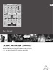
DIGITAL PRO MIXER
Ultimate 5-Channel Digital DJ Mixer with Sampler, 4 FX Sections, Dual BPM Counters and MIDI
DDM4000
== 32-bit digital DJ mixer with beat-synchronized sampler, 4 multi-FX sections, 2 patented1 BPM counters, digital crossfader and MIDI
== 4 Phono/Line stereo channels allowing max. 8 signal sources to be connected simultaneously
== 2 Microphone inputs with Gain, EQ, Talk function and FX
== 4 stereo channels with Gain, programmable parametric 3-band EQ with Kill function, fader curve
control and flexible crossfader assignment
== Fully featured MIDI controller for your DJ software
== Sophisticated sampler with beat-controlled loop function, real-time pitch control, sampler FX and
crossfader start option
== 2 freely assignable and BPM-synchronized, high-quality FX engines (Bitcrusher, Resonator, Reverb,
Flanger, etc.)
== Ultra-fast, accurate and patented BPM counters for automatic BPM synchronization of sampler, FX,
crossfader and external drum machines, etc. via MIDI
== Digital crossfader with flexible curve adjustment, reverse button and automatic, BPM-synchronized
crossfading
== Dual-mode crossfader with innovative frequency-selective crossfading
== Dedicated Headphone section includes PFL Mix/Split and Bass/Snare boost functions
== Recall your last mixer setting at the push of a button
== Digital S/PDIF output for direct recording of your performance
== Rack mount brackets included for ultimate flexibility
== High-quality components and exceptionally rugged construction ensure long life
== Conceived and designed by BEHRINGER Germany
1) U.S. Patent No.: 6812394 / German Patent No.: 102 23 735
3
DIGITAL PRO MIXER DDM4000
Foreword
Dear Customer,
Welcome to the team of
BEHRINGER users, and
thank you very much for
expressing your confidence in us by purchasing
this device.
Writing this foreword
for you gives me great
pleasure, because it represents the culmination
of many months of hard
work delivered by our engineering team to achieve
a very ambitious goal: to
design a digital DJ mixer
that offers a maximum of
performance thanks to its
one-of-a-kind functions
and intuitive control. The
task of designing our new
DDM4000 certainly meant
a great deal of responsibility, which we assumed by focusing on
you, the discerning user and musician. Meeting your expectations
also meant a lot of work and night shifts. But it was fun, too. Developing a product usually brings a lot of people together. What a
great feeling it is when all who participated in such a project can
be proud of what they’ve achieved.
It is our philosophy to share our enjoyment with you, because you
are the most important member of the BEHRINGER team. With
your highly competent suggestions for new products you’ve made
a significant contribution to shaping our company and making it
successful. In return, we guarantee you uncompromising quality
as well as excellent technical and audio properties at an extremely
reasonable price. All of this will enable you to give free rein to your
creativity without being hampered by budget constraints.
We are often asked how we manage to produce such high-quality
devices at such unbelievably low prices. The answer is quite
simple: it’s you, our customers! Many satisfied customers mean
large sales volumes, enabling us to get better purchasing terms
for components, etc. Isn’t it only fair to pass this benefit on to you?
Because we know that your success is our success, too!
I would like to thank everyone who has made the DDM4000 possible. You have all made your own personal contributions, from
the developers and the many other employees at this company,
to you, the BEHRINGER user.
My friends, it’s been worth the effort!
Thank you very much,
Uli Behringer
Table of contents
1. Introduction.......................................................................... 5
1.1 Before you get started................................................... 5
1.1.1 Shipment.............................................................. 5
1.1.2 Initial operation.................................................... 5
1.1.3 Online registration................................................ 5
2. Controls and connections.................................................. 6
2.1 Stereo channels 1 – 4................................................... 7
2.2 Microphone channel...................................................... 7
2.3 Crossfader section........................................................ 8
2.4 Main and Phones section.............................................. 9
2.5 BPM and Effects section............................................... 9
2.6 Sampler....................................................................... 10
2.7 Rear panel connectors................................................ 10
2.8 Rear panel outputs.......................................................11
2.9 Power section...............................................................11
2.10 Hookup example....................................................... 12
3. Operation........................................................................... 13
3.1 Console Setup............................................................. 13
3.1.1 Selection lists on screen.................................... 13
3.2 Using stereo channels................................................. 13
3.2.1 EQ modes: SINGLE and MULTI........................ 13
3.2.2 Channel Setup................................................... 14
3.3 Operating the Microphone channel............................. 14
3.3.1 Mic Setup........................................................... 14
3.3.2 Talk Setup.......................................................... 16
3.4 Operating the crossfader............................................. 16
3.4.1 Crossfader modes: KILL and X-OVER.............. 16
3.4.2 Crossfader Setup............................................... 16
3.4.3 Bounce to MIDI Clock........................................ 16
3.5 Operating the Main section......................................... 16
3.5.1 Ultramizer.......................................................... 16
3.5.2 Loading and saving user settings...................... 17
3.6 Operating the Phones section..................................... 17
4. BPM and Effects section.................................................. 17
4.1 Effects section............................................................. 18
4.1.1 Selecting the signal source................................ 18
4.1.2 Activating an effect............................................. 18
4.1.3 Selecting an effect............................................. 18
4.1.4 Effect descriptions............................................. 18
4.1.5 Editing effects.................................................... 19
4.1.6 BPM-synchronized effect parameters................ 19
4.1.7 FX Setup............................................................ 20
4.2 BPM Counter............................................................... 20
4.3 MIDI Clock................................................................... 21
5. Sampler.............................................................................. 21
5.1 Recording samples..................................................... 21
5.2 Playing back samples................................................. 22
5.2.1 Insert function.................................................... 22
5.2.2 Reverse and Loop playback.............................. 22
5.2.3 Crossfader start................................................. 22
5.2.4 Pitch Bend......................................................... 22
5.3 Sampler effect............................................................. 22
6. Further settings................................................................. 23
6.1 Loading factory settings.............................................. 23
6.2 Output Setup............................................................... 23
6.3 Adjusting display contrast............................................ 23
7. The DDM4000 as MIDI controller...................................... 23
7.1 MIDI protocol............................................................... 23
7.2 Common MIDI settings................................................ 23
7.2.1 Setting the MIDI channel................................... 24
7.2.2 Sending a MIDI dump........................................ 24
7.3 Configuring Microphone channel, Sampler and
crossfader as MIDI controller...................................... 24
7.4 Configuring stereo channels as MIDI controller.......... 24
8. Installation......................................................................... 24
9. Specifications.................................................................... 25
10. Appendix.......................................................................... 26
11. Warranty .......................................................................... 27
4
DIGITAL PRO MIXER DDM4000
1. Introduction
Caution!
Congratulations! The DDM4000 is a state-of-the-art 32-bit digital
DJ mixer, jam-packed with creative tools, yet its intuitive layout
will let you feel at home in an instant. Editing, storing and recalling
your settings is simply a breeze!
++ Before changing the fuse, switch off the device and
pull the plug to avoid electric shock or damage to the
device.
Hook up your turntables and CD/MP3 players to its 4 stereo
channels, each with fully programmable EQ and Kill switches. Put
ultimate versatility at your fingertips with fully programmable beatsync’able multi-FX modules, a pair of high-precision BPM counters
and a digital crossfader with custom curve adjustment. And the
super-cool BPM-sync’d sampler with real-time pitch control, loop
and reverse functions will make your crowd go wild.
The DDM4000 power connection is made by using the enclosed
cable and the amplifier’s standard IEC receptacle. It meets all of
the international safety certification requirements.
++ Please make sure that all units have a proper earth
connection. For your own safety, never remove or
disable the earth conductor from the unit or of the AC
power cord.
++ Please read this manual to familiarize yourself with the
control elements of the unit and its functions. After
you have carefully read this manual, keep it for future
reference.
1.1 Before you get started
1.1.1 Shipment
Your DDM4000 was carefully packed at the factory, and the
packaging was designed to protect the unit from damage caused
by rough handling. Nevertheless, we recommend that you carefully
examine the packaging and its contents for any signs of physical
damage that may have occurred during transit.
++ If the unit is damaged, please do NOT return it to us;
instead, notify your dealer and the shipping company
immediately, otherwise claims for damage or replacement may not be granted.
++ We recommend using a case to ensure optimal protection of the device.
++ Please always use the original packaging to avoid damage due to storage or shipping.
++ Never let unsupervised children play with the DDM4000
or with its packaging.
++ Recycle whenever possible.
IMPORTANT NOTES CONCERNING
INSTALLATION
++ The sound quality may diminish within the range of powerful broadcasting stations and high-frequency sources.
Increase the distance between the transmitter and the
device and use shielded cables for all connections.
1.1.3 Online registration
Please do remember to register your new BEHRINGER equipment
right after your purchase by visiting www.behringer.com (alternatively www.behringer.de) and kindly read the terms and conditions
of our warranty carefully.
Should your BEHRINGER product malfunction, our goal is to
have it repaired as quickly as possible. To arrange for warranty
service, please contact the retailer from whom the equipment
was purchased. Should your BEHRINGER dealer not be located
in your vicinity, you may directly contact one of our subsidiaries.
Corresponding contact information is included in the original equipment packaging (Global Contact Information/European Contact
Information). Should your country not be listed, please contact the
distributor nearest you. A list of distributors can be found in the
support area of our website (www.behringer.com).
Registering your purchase and equipment with us helps us process
your repair claims quicker and more efficiently.
Thank you for your cooperation!
1.1.2 Initial operation
Caution!
Ensure adequate air supply and to avoid overheating do not place
the unit near radiators etc.
++ Before you connect your DDM4000 to the mains, please
make sure that your local voltage matches the voltage
required by the unit.
Caution! The following applies only to units that can be switched
between 120 V and 230 V: The fuse holder on the mains connector
has 3 triangular markings, with two of these triangles opposing
each other. The DDM4000 is set to the operating voltage printed
next to these markers and can be set to another voltage by turning
the fuse holder by 180°.
++ Extreme output volumes may damage your hearing and/
or your loudspeakers. Turn down all volume and level
controls before you switch on the unit. Always set the
volume to an appropriate level.
++ Please note that when operating the unit at 120 V,
a higher fuse rating is required. Please refer to the
“Specifications” for details.
++ If you set the unit to a different mains voltage, be sure
to use a fuse of the correct type and rating. Please refer
to the “Specifications” for details.
++ Blown fuses must be replaced by fuses of the same
type and rating! Please refer to the “Specifications”
for details.
Introduction
5
DIGITAL PRO MIXER DDM4000
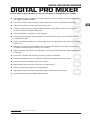
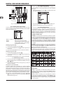
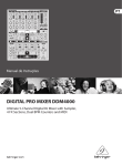
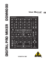
2. Controls and connections
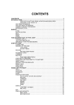
This chapter describes the various controls and connections of the DDM4000 mixer. We have divided the console into several functional
sections for a better overview.
Fig. 2.0: Overview of DDM4000
2.1
Stereo channels 1 – 4
2.2
Microphone channel
2.3
Crossfader section
2.4
Main and Phones section
2.5
BPM and Effects section
2.6
Sampler
2.7
Rear panel connectors
2.8
Rear panel outputs
2.9
Power section
6
Controls and connections
DIGITAL PRO MIXER DDM4000
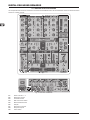
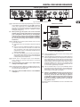
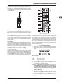
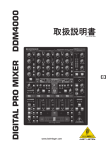
2.1 Stereo channels 1 – 4
2
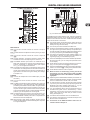
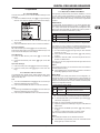
2.2 Microphone channel
1
3
5
4
6
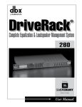
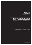
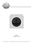
Fig. 2.2: Microphone channel
7
[11] The GAIN knob adjusts the level of the microphone signal
at the MIC 1 input.
9
8
10
[12] This switch determines which signal is to be displayed on the
level meter [13]. IN VU shows the unprocessed input level
which helps you to adjust the microphone signal correctly.
XMC VU shows the level after it has passed the Ultramic
processor.
[13] The 7-segment LED meter indicates the level of the microphone channel.
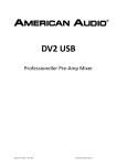
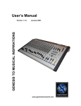
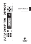
Fig. 2.1: Stereo channel strips
[14] The microphone channel strip features a 3-band equalizer
(HIGH, MID and LOW). The range is +/-12 dB.
{1} The input select switch lets you switch between two signal
sources. Select Line to hear the signal of the Line input [67].
Select Phono/Line to listen to the incoming source signal at
the Phono/Line [68] input.
[15] The ON/OFF push button turns the microphone channel
on and off.
{2} The GAIN knob adjusts the level of the input signal. The
actual level is displayed on the level meter {3}.
{3} The 7-segment LED meter indicates the level of the input
signal.
{4} Each input channel features a 3-band equalizer (HIGH, MID
and LOW) with kill feature, giving you up to 12 dB of boost
and a maximum cut of -? dB (kill). The kill feature lets you
mute the given frequency range. When each EQ knob is
turned fully left, the signal is effectively muted. All EQ parameters can be adjusted in Channel Setup.
{5} The MODE push button changes the functionality of the
preset push button {6} from Multi to Single.
[16] The MIC SETUP push button opens the Mic Setup menu
on the display. This allows you to adjust the settings of the
equalizer, the Ultramic processor and the MIC FX (effects
processor).
[17] The XMC ON push button activates the ULTRAMIC processor, which includes a 2-band compressor and expander.
Ultramic settings can be adjusted in Mic Setup.
[18] The MIC FX ON push button activates the microphone effects
processor. Select the effect in Mic Setup.
[19] The TALK ON push button activates the Talkover function.
This attenuates the volume level of the music as soon as you
speak into the microphone. This is a very useful function to
make yourself heard over the music being played. You can
adjust all the relevant settings in Talk Setup.
{6} The preset push buttons P1, P2 and P3 allow you to store
and activate equalizer presets. When activated in Single
Mode, these push buttons provide a maximum cut of
-? dB (kill function).
{7} Press the PFL push button to listen in on the channel’s signal
using headphones.
{8} The fader controls the channel volume.
{9} The CURVE switch adjusts the response of the fader. In
SOFT Mode, the fader responds slower to steady fader
movement in the upper range and quicker in the lower range.
In Sharp Mode, the fader adjusts the volume quicker in the
upper third and slower in the lower range. In MID Mode,
the fader responds in a linear fashion. Since a difference
in volume levels is heard when switching between modes,
don’t use this switch while playing music!
[10] The CF ASSIGN push button lets you determine on which
side of the crossfader [20] (A or B) the signal is to be heard.
Controls and connections
7
DIGITAL PRO MIXER DDM4000
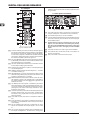
2.3 Crossfader section
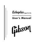
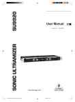
Fig. 2.3: Crossfader section
[20] The replaceable crossfader is used to fade between the
signals that are assigned to its two sides A and B. You can
assign the stereo channels and sampler using the CF Assign
push buttons [10] and [65].
[21] The CF ON push button activates the crossfader. When
the push button is not pressed, the signals of the individual
channels are routed straight to the Main outputs.
[22] There are 3 Kill push buttons (HIGH, MID and LOW) on each
side of the crossfader which let you mute the given frequency
range. In Crossfader Setup (see Chapter 3.4.2), it is possible to activate a special X-OVER mode that enhances the
crossfader’s functionality in combination with the Kill push
buttons. For more information, read Chapter 3.4.1.
[23] Press the FULL FREQ push button to remove any frequency
cuts of the KILL EQ [22].
[24] The CURVE knob lets you seamlessly adjust the response
of the crossfader.
The BOUNCE TO MIDI CLOCK function provides an automatic, quick crossfading synchronized to the rhythm of the music
(“bouncing”). The bounce speed is determined by the MIDI
Clock.
[27] Press the BOUNCE TO MIDI CLK push button to activate the bouncing. Once the push button is pressed,
the signal repeatedly jumps from A to B and back again
corresponding to the interval pre-selected by using the BEAT
push buttons [28].
[28] The BEAT push buttons let you determine the Bounce rate,
which can range between one and 16 beats.
[29] These LEDs indicate the number of beats you have
chosen.
++ Find a detailed description of this function in Chapter
3.4.3.
The REVERSE function allows you to reverse the configuration of
the crossfader. This way you can toggle between Channel A and
B at the flick of a switch.
[25] REVERSE HOLD activates a permanent Reverse function.
The crossfader fades between sides A and B in the reverse
direction. This means that A is now on the right and B on
the left side.
[26] REVERSE TAP activates a momentary Reverse function.
This means that A and B are interchanged as long as the
TAP push button is held down.
8
Controls and connections
DIGITAL PRO MIXER DDM4000
2.4 Main and Phones section
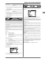
2.5 BPM and Effects section
Fig. 2.5: BPM Counter and Effects section (here FX1)
The DDM4000 has 2 identical effects units. There are 2 additional
independent effects units for the mic signal and the Sampler. All
effects can be used at the same time. The BPM Counter and MIDI
Clock are also found in this section.
Fig. 2.4: Main and Phones section
[41] The graphic display shows BPM values, effect names and
effect parameters as well as channel assignments. It also
leads you through Console Setup.
[42] The FX ON push button activates the effects unit.
MAIN OUTPUT:
[30] The OUTPUT A knob controls the volume of output A
([73]).
[31] The BALANCE knob adjusts the stereo panning of output
A.
[32] The OUTPUT B knob controls the volume of output B
([74]).
[33] The high-resolution, 22-segment OUTPUT LEVEL meter
indicates the level of the output signal on OUTPUT A.
[34] ULTRAMIZE ON/OFF push button: The Ultramizer is an
effect that enhances the loudness and assertiveness by
dynamic compression. In Ultramizer Setup (see Chapter
3.5.1), you can configure the Ultramizer.
[35] The LOAD push button lets you load the user settings of the
entire mixer. The settings that are active when the device is
turned off are loaded when the device is switched back on
again. Read more about saving and loading user settings
in Chapter 3.5.2.
PHONES:
[36] Connect the headphones to the PHONES jack (1/4" TRS
connector).
[37] The OUTPUT knob controls the volume of the headphones.
[38] The MIX knob adjusts the balance between PFL signal and
PGM signal (PFL = Pre Fader Listening, fader independent
pre-listening of individual channels; PGM = Program, Master
signal). When the knob is turned completely to the left, you
only hear the PFL signal, whereas when turned completely
to the right the Master signal is heard. Between these two
positions, you can adjust the mix of both signals.
[39] The PUNCH EQ function helps synchronize two tracks. You
can orient yourself to the snare or the bass drum or both.
Press the SNARE or BASS push button to emphasize the
selected sound in the headphones.
[40] When the SPLIT push button is pressed, the PFL signal is
heard in the left headphone and the PGM signal is only heard
in the right headphone.
[43] Press the FX ASSIGN push button to assign an effects unit
to a signal source (push button flashes). The possible input
sources are listed on the display. Select the preferred source
by turning and pressing the PARAMETER knob [45].
[44] The DEPTH knob adjusts the effect intensity (depth). For
some effects, it also lets you adjust the mix between the
original signal (dry) and the effect signal (wet).
[45] Press the PARAM(eter) knob to select the effect parameters.
By turning the knob, you can change the parameter shown
on the display.
[46] Press SELECT/LOW to access the effects list (on the display). Turn and press the knob [45] to load a preset.
[47] Press the PARAM/MID push button to access the effect parameters. Turn the knob [45] to change the parameter value.
[48] Press DEFAULT/HIGH to restore a preset.
++ When the effect is activated (by pressing the FX ON
push button), the push buttons [46] (LOW), [47] (MID)
and [48] (HIGH) are used as Kill switches in the effect’s
signal path.
[49] Depending on the selected effect, the BEAT push buttons can
adjust time-related parameters. However, the values entered
are not in milliseconds or similar units, but in beats.
[50] To enter the tempo manually, tap this push button (at least
2 x) in the rhythm of the music (TAP). By keeping the AUTO
BPM/TAP push button pressed a little longer (> 1 s), the
automatic tempo input (AUTO BPM) is reactivated.
[51] Turn the CONSOLE SETUP knob to adjust the tempo of
the MIDI Clock (press and turn simultaneously = coarse
adjustment). A short press on the knob confirms the entry
made. A long press on the knob lets you access Console
Setup (see Chapter 3.1).
[52] The MIDI START/STOP/ESC turns on the MIDI Clock.
[53] The ADJUST push buttons let you transfer the tempo of the
BPM counter to the MIDI Clock.
++ All functions of the BPM and Effects section are described in detail in Chapter 4.
Controls and connections
9
DIGITAL PRO MIXER DDM4000
2.6 Sampler
the CF START push button. But beforehand, use BANK
ASSIGN to select the bank that should be played back when
using the fader.
2.7 Rear panel connectors
Fig. 2.7: Rear panel connectors
[67] The LINE inputs are used to connect the Line signals (for
example, CD players, soundcards and drum machines).
[68] The PHONO inputs let you connect turntables.
[69] Use the PHONO/LINE switches to set the PHONO inputs to
Line level in order for you to be able to connect a CD player
to the PHONO inputs.
++ Caution! Devices with Line output levels, such as CD
players, can cause distortion and destroy the preamplifier. Press the PHONO/LINE switch before connecting
devices with Line level to the highly sensitive PHONO
inputs.
Fig. 2.6: Sampler section
[54] Press the INSERT push button to add the sampler signal to
the channel (Insert Mode). If the push button is not activated,
the sampler is mixed to the selected channel (Mix Mode).
In both cases, playback is initiated with the REC SOURCE
push buttons. When the sampler is routed to the crossfader,
the LED of the INSERT push button goes out.
[70] The GND connectors are used to ground the turntables.
[71] The balanced XLR connectors provide a connection for
dynamic microphones.
[72] This is the LEVEL control for the MIC 2 input.
[55] The VOLUME/MIX knob controls the volume of the sampler
(in Mix Mode) as well as the volume balance between input
signal and Sampler (in Insert Mode).
[56] The REC SOURCE push buttons let you select the channel
for recording and playing back samples.
[57] Press the PFL push button to listen in on the sampler signal
with the headphones.
[58] SAMPLE LENGTH adjusts the recording time (1 – 16 beats
or endless recording ?).
[59] RECORD/IN lets you record to the Sampler. Select a bank
beforehand. By pressing the push button a second time, the
recording is stopped (only in ? Mode).
[60] BANK ASSIGN is used to select a bank in which the recorded material is stored. The selected bank is indicated by
the relevant MODE push button [61] which signalizes the
readiness to record.
[61] The MODE push buttons (Bank 1 and Bank 2) are used to
select the sampler’s types of playback (Reverse and Loop).
A short tap activates or deactivates the Reverse function;
pressing the push button a little longer activates or deactivates the Loop function.
[62] Press the PLAY/OUT push button to start the playback of the
recorded sample. When the Loop function is deactivated,
the sample is only played back as long as the PLAY push
button is pressed.
[63] Press SMP FX ON push button to activate the Brake effect.
[64] Press the SELECT push button to determine the length of
the brake (1, 4 or 8 Beat Brake, which is shown in the center
of the display).
[65] The CF ASSIGN push button lets you determine on which
side of the crossfader the sampler signal is to be routed
to.
[66] You can even trigger the sampler with the crossfader when
the sampler is assigned to it. To order to do so, simply press
10
Controls and connections
DIGITAL PRO MIXER DDM4000
2.8 Rear panel outputs
Fig. 2.8: Rear panel connectors
2.9 Power section
[73] These are the OUT A outputs (XLR) allowing you to connect
to an amplifier. Use the OUTPUT A control [30] to adjust the
volume level. Additionally, the SUBWOOFER output lets
you hook up a subwoofer. A crossover is integrated into the
DDM4000. The crossover frequency is adjusted in Output
Setup (see Chapter 6.2).
++ When powering up the system, turn on the connected
amplifier last to prevent spikes that can easily damage
your loudspeakers. Before turning on the amplifier,
make sure that no signal is going through the DDM4000
in order to avoid sudden and unpleasant surprises.
We recommend turning down all faders and knobs
beforehand.
79
78
[74] The MAIN OUT connector panel consists of OUT A, OUT
B and TAPE outputs:
== The signal at OUT A is the same as at the XLR outputs
[73].
77
== You can connect an additional amplifier to output OUT
B which can be used for a DJ booth or a second club
zone, for example. The volume of the OUT B signal is
(independent of OUT A) individually adjusted with the
OUTPUT B knob [32].
== The TAPE output allows you to connect a recording device in order to tape-record your mix. The output level is
independent of OUT A and OUT B and can be adjusted
in Output Setup (see Chapter 6.2).
[75] DIGITAL OUT is the digital output of the DDM4000.
This is where you find the TAPE signal in CD quality
(16 bit/44.1 kHz).
++ Use Output Setup (see Chapter 6.2) to adjust further
settings of the output section.
[76] These are the MIDI IN, MIDI OUT and MIDI THRU connectors that allow you to connect external MIDI equipment and
synchronize with their MIDI Clock.
++ Read more about the MIDI functions of the DDM4000
in Chapter 7.
Fig. 2.9: The POWER section
[77] Power is supplied via an IEC connector. The matching cable
is provided with the unit.
[78] FUSE RETAINER/VOLTAGE SELECTOR. Please make sure
that the voltage indicated by the voltage selector matches the
local voltage before you connect the unit to the main power
supply. Always replace blown fuses with fuses of the same
type and rating. Some units feature a fuse retainer in which
a selection between 230 V and 120 V is possible. Please
be aware: When using your unit outside of Europe with 120
V, a fuse with a higher rating is required.
[79] Use the POWER switch to turn on the DDM4000. Before
connecting the unit to the power mains, ensure that the POWER switch is in OFF position. When the unit is in operation,
ensure that the mains plug is accessible.
++ Attention: The POWER switch does not fully disconnect
the unit from the mains. To disconnect the unit from
the mains, pull out the main cable plug or appliance
coupler. When installing the product, ensure the plug
or appliance coupler is readily operable. Unplug the
power cord completely when the unit is not used for
long periods of time.
The serial number of the DDM4000 is found on the bottom side
of the device.
Controls and connections
11
DIGITAL PRO MIXER DDM4000
2.10 Hookup example
CD players
Turntables
Microphones
Drum Computer
Digital recorder
Dancefloor
DJ Booth
Fig. 2.10: Application example of hooking up the DDM4000
12
Controls and connections
DIGITAL PRO MIXER DDM4000
3. Operation
3.2 Using stereo channels
3.2.1 EQ modes: SINGLE and MULTI
3.1 Console Setup
Console Setup allows you to make all standard settings for the
DDM4000.
1) Press the CONSOLE SETUP knob [51] for approximately 2
seconds. The setup list appears in the center of the display.:
The equalizer provides Preset push buttons, labeled P1, P2 and
P3, with which preset configurations are stored. The behavior
of the push buttons depend on the selected EQ mode: Single
Mode or Multi Mode. After switching on the device, Single Mode
is active.
SINGLE Mode:
In Single Mode, the push buttons P1, P2 and P3 {6} are each
permanently assigned to a frequency band (P1 = HIGH, P2 = MID,
P3 = LOW). This means that a Preset can be assigned to each
EQ control. When activated, the Preset push buttons provide a
Kill function with maximum attenuation (-? dB).
Preset settings in SINGLE Mode
2) Turn the CONSOLE SETUP knob to select the setup you
want to edit.
3) Press the CONSOLE SETUP knob to confirm the selection.
P1
HIGH Kill -? dB
Suppresses high frequencies
P2
MID Kill -? dB
Suppresses mid frequencies
P3
LOW Kill -? dB
Suppresses low frequencies
Tab. 3.1: Functionality of Preset push buttons in Single Mode
== Press the ESC push button [52] to exit Console Setup.
The degree of cut can, however, be modified. Alternatively, a frequency boost can also be stored. In case you want to boost instead
of cutting the bass (Punch function), proceed as follows:
Some of the setup pages can be accessed in different ways. This
is the case for Mic Setup and User Settings:
1) Turn the LOW knob {4} to the right until you have reached
the boost you want.
Open Mic Setup:
2) Press and hold the MODE push button {5} while pressing
P3 {6}.
Exit Console Setup:
1) Press the MIC SETUP push button [16] to access Mic
Setup.
2) Press the MIC SETUP push button [16] again to exit Mic
Setup.
Open User Settings:
1) Press the LOAD push button [35] to access User Settings.
2) Press the LOAD push button [35] again to exit User Settings.
3.1.1 Selection lists on screen
The individual setup pages contain further selection lists, which
appear either on the left or right side of the display, in addition to
the Console Setup list.
Left:
1) Turn the left PARAMETER knob [45] (in the FX1 section) to
select the preferred function from the list.
3) Press P3 to load the Preset. The bass frequencies are now
boosted. P3 flashes blue.
This way you can also program the mids and highs with P2 and
P1 respectively.
Reset:
The Preset push buttons can be restored to their initial states at
all times (Reset function):
== Press MODE {5} for approximately 2 seconds. The MULTI
LED briefly lights up to confirm the reset.
MULTI Mode:
In Multi Mode, the Preset push buttons are not assigned to individual EQ bands, but are assigned to the 3-band equalizer as
a whole. This way you can create three EQ presets and assign
these to the Preset push buttons. When activated, the Preset push
buttons are assigned as follows:
2) Press the left PARAMETER knob to confirm the selection.
Preset settings in MULTI Mode
P1
High pass
Suppresses MID and LOW
Right:
1) Turn the right PARAMETER knob [45] (in the FX2 section) to
select the preferred function from the list.
2) Press the right PARAMETER knob to confirm the selection.
P2
Band pass
Suppresses HIGH and LOW
P3
Low pass
Suppresses HIGH and MID
Tab. 3.2: Functionality of Preset push buttons in Multi Mode
== To activate Multi Mode, press the MODE push button {5}.
The MULTI LED lights up.
To create your own EQ presets, proceed as follows:
1) Adjust the equalizer as needed by turning the LOW, MID and
HIGH knobs.
2) Press and hold the MODE push button {5} while pressing
P1 {6}.
3) Press P1 to load the EQ Preset. P1 flashes yellow.
Two more EQ Presets can be stored with P2 and P3.
Reset:
The Preset push buttons can be restored at all times:
== Press MODE for approximately 2 seconds. The SINGLE LED
briefly lights up to confirm the reset.
Operation
13
DIGITAL PRO MIXER DDM4000
3.2.2 Channel Setup
In Channel Setup, you can fine-tune the characteristics of the
stereo channels’ equalizer. It is also possible to adjust a Subsonic
Filter (low-cut filter) for all four channels. For example, this filter can
be used to suppress low-frequency noise from turntables.
1) Press the CONSOLE SETUP knob [51] for approximately 2
seconds.
2) Select “Channel Setup” by turning and pressing the CONSOLE
SETUP knob.
Channel Setup appears on the display.
3.3 Operating the Microphone channel
3.3.1 Mic Setup
You can make adjustments to the sound settings of the Microphone
channel, the Ultramic processor and the Mic effects by using Mic
Setup. This is how to access Mic Setup:
1) Press the CONSOLE SETUP knob [51] for approximately 2
seconds.
2) Select “Mic Setup” by turning and pressing the CONSOLE
SETUP knob.
Alternatively, you can access Mic Setup as follows:
The equalizer of the stereo channels has 3 bands with different
characteristics. The Mid band is a peak filter whose center frequency and bandwidth (Q factor) can be modified. Both outer
bands Low and High are shelving filters. In Channel Setup,
following settings are available for each of the 4 channels:
== Press the MIC SETUP push button [16] on the microphone
channel. The MIC SETUP push button lights up as long as
you are using Mic Setup.
Mic Setup appears on the display containing several submenus.
On the left-hand side of the display you see a list from which the
following submenus can be selected:
Channel Xover (Crossover):
LOW:
MID:
HIGH:
Cutoff frequency of the Low filter. All frequencies below
the adjusted value are cut or boosted.
Center frequency of the Mid band. All frequencies
around this value are boosted or cut. The bandwidth is
determined by the parameter Mid Q (see below).
Cutoff frequency of the High filter. All frequencies above
the adjusted value are boosted or cut.
== Turn the left PARAMETER knob [45] to select the submenu
you want to edit:
1) Press the left PARAMETER knob [45] to select the parameter
(LOW, MID or HIGH).
2) Turn the PARAMETER knob to change the cutoff frequency
and center frequency of the selected band.
Mid Q:
The Q factor determines the behavior of the filter. The higher the
value, the narrower the bandwidth. Mid Q affects the mids band.
== Turn the CONSOLE SETUP knob [51] to change the value
of the Q factor.
Subsonic frequency:
You can adjust the cutoff frequency of the low-cut filter on each
stereo channel. All frequencies below the cutoff frequency are
attenuated.
1) Press the right PARAMETER knob [45] to select the channel.
2) Turn the PARAMETER knob to change the cutoff frequency.
Exiting Channel Setup:
== Press the ESC push button [52] to exit Channel Setup.
EQ Freq/Pan page:
This page shows level meters for both microphone signals. In
addition, you can make sound settings for the equalizer on the
Microphone channel. Here you can adjust the stereo image of the
microphone signal as well as the signal relation of both microphones to each other. The individual parameters are as follows:
MIC1:
MIC2:
LOW:
MID:
HIGH:
Q MID:
Level meter for Microphone 1
Level meter for Microphone 2
Cutoff frequency of the LOW control knob
Center frequency of the MID control knob
Cutoff frequency of the HIGH control knob
Q factor of the mids band
1) Press the CONSOLE SETUP knob [51] to select the parameter
(LOW, MID, HIGH, Q MID).
2) Turn the CONSOLE SETUP knob to change the value of the
selected parameter.
PAN1:
PAN 2:
OUT B:
Position of Microphone 1 in the stereo image
Position of Microphone 2 in the stereo image
Volume of the microphone channel at Output B
1) Press the right PARAMETER knob [45] to select the parameter
(PAN 1, PAN 2, OUT B).
2) Turn the PARAMETER knob to change the value of the
parameter.
EQ GAIN page:
This page lets you make user default sound settings, which affect
the microphone channel in relation to the equalizer. For example,
storing a boost of 5 dB in these settings affects the signal even
when the HIGH rotary knob is set to 0, that is the center position.
The high frequencies can additionally be boost or cut with the HIGH
knob. This function helps to remove problematic frequencies of
your voice or to improve speech comprehensibility.
14
Operation
DIGITAL PRO MIXER DDM4000
MIC1 LOW CUT:
Cutoff frequency of the high-pass filter
(Microphone 1)
MIC1 LOW, MID, HIGH: EQ default settings for Microphone
1
1) Press the CONSOLE SETUP knob [51] to select the parameter
(LOW, MID, HIGH).
2) Turn the CONSOLE SETUP knob to change the value of the
selected parameter.
MIC FX page:
On the Mic FX page, you can select the type of effect you want
to use for the microphone signal. The following effects are
available:
MIC2 LOW CUT:
Cutoff frequency of the high-pass filter
(Microphone 2)
MIC2 LOW, MID, HIGH: EQ default settings for Microphone 2
1) Press the right PARAMETER knob [45] to select the parameter
(LOW, MID, HIGH).
2) Turn the PARAMETER knob to change the value of the
selected parameter.
ULTRAMIC 1 and 2:
1) Turn the right PARAMETER knob [45] to select the preset.
2) Press the PARAMETER knob to load the preset.
The Ultramic processor is a 2-band compressor that reduces the
dynamic range of speech. The level of loud sounds is reduced
and the level of quiet sounds is raised. This decreases the difference between the loudest and quietest passages. By splitting the
signal into two frequency bands, a thicker, more powerful sound
is achieved without the typical artifacts, such as pumping sound
or a loss of clarity.
The settings for both microphone signals are made separately.
That’s the reason for having two Ultramic pages. For Mic 1, select
the page “Ultramic 1” and choose “Ultramic 2” for Mic 2. The
parameters on both pages are identical so that they only have to
be described once.
You can see several level meters on the display. Three parameters of the compressor are adjustable plus you can also load
presets.
The meters:
MIC I
Shows the input level
MIC 0
Shows the output level
COM
Shows the compression ratio for the low (L) and high
(H) frequency band
EXP
Shows the attenuation of the expander for the low (L)
or high (H) frequency band
Adjustable parameters
THRSH Threshold specifies the cutoff frequency of the Ultramic processor
FREQ
Adjusts the crossover frequency between the upper
and lower frequency band
EFFIC
Efficiency: Adjusts the level of compression
1) Press the CONSOLE SETUP knob [51] to select the parameter
(THRSH, FREQ, EFFIC).
Each effect can be modified in order to suit your individual taste.
Two parameters are available for this reason. The second parameter always adjusts the effect Dry/Wet Mix—this applies to all
effects.
Effect descriptions:
FLANGER: A flanger effect occurs through frequency modulation. You can adjust the speed of the LFO (Low Frequency
Oscillator).
PHASER is similar to a flanger. Only this time around, modulation
is achieved through phase-shifting. You can adjust the speed of
the LFO.
DELAY is a signal delay. You can change the delay time (Time).
ECHO is similar to the delay effect, with the difference that the
delayed signal is repeated several times.
PITCH changes the pitch of the signal and therefore the pitch of the
vocalist’s and speaker’s voice. Shift is used to adjust the pitch.
BITCRUSHER reduce the digital resolution. The bit depth is
adjustable.
REVERB is a reverberation effect. Eight different types of reverberation are available. These are described in detail in Chapter
4.1.4.
1) Press the CONSOLE SETUP knob [51] to select a parameter.
2) Turn the CONSOLE SETUP knob to change the value of this
parameter.
You can match the time parameter of the flanger, phaser, delay
and echo effects to the beat by tapping the tempo with the left TAP
push button (50) as long as Mic Setup is displayed (MIC SETUP
push button [16] shines when active).
Exiting Mic Setup:
== Press the ESC push button [52] to exit Mic Setup.
2) Turn the CONSOLE SETUP knob to change the value of the
selected parameter.
Ultramic presets:
The following default settings can be loaded:
1) Turn the right PARAMETER knob [45] to select the preset.
2) Press the PARAMETER knob to load the preset.
Operation
15
DIGITAL PRO MIXER DDM4000
3.3.2 Talk Setup
3.4.2 Crossfader Setup
The Talkover function is useful when making announcements
while the music is playing. The level of the music, is attenuated
as soon as you speak into the microphone. All necessary settings
of this function are made in Talk Setup. This is how you access
Talk Setup:
1) Press the CONSOLE SETUP knob [51] for approximately 2
seconds.
This is how you access Crossfader Setup:
1) Press the CONSOLE SETUP knob [51] for approximately 2
seconds.
2) Select “Crossfader Setup” by turning and pressing the CONSOLE SETUP knob.
The Crossfader Setup page appears on the display:
2) Select “Talk Setup” by turning and pressing the CONSOLE
SETUP knob.
The Talk Setup page appears on the display.
On the display’s left side, you can adjust the frequency crossfade
of the Kill push buttons. On the right side, you can select Crossfader Mode.
This page displays level meters for both microphones. On the
left-hand side of the screen, there is a list from which you can
select a Talkover preset.
Loading presets:
Editing talkovers:
The following parameters of the Talkover function are adjustable:
SPEED
Crossover frequency between LOW and MID
Crossover frequency between MID and HIGH
2) Turn the PARAMETER knob to change the value fo the
selected parameter.
2) Press the PARAMETER knob to load the preset.
MAX. ATT
LOW:
HIGH:
1) Press the left PARAMETER knob [45] to select the parameter
(LOW, HIGH).
1) Turn the left PARAMETER knob [45] to select the preset.
THRSH
XOVER CF (Crossover Center Frequency):
Threshold. The music signal is attenuated as soon
as the microphone signal exceeds this value.
Maximum Attenuation. This lets you adjust the
music’s maximum attenuation while speaking into
the microphone.
Adjusts the speed at which the signal’s volume
level is reduced.
Crossfader Mode:
1) Turn the right PARAMETER knob [45] to select the mode
(KILL, X-OVER).
2) Press the PARAMETER knob to confirm.
Exiting Crossfader Setup:
== Press the ESC push button [52] to exit Crossfader Setup.
3.4.3 Bounce to MIDI Clock
1) Press the right PARAMETER knob [45] to select the parameter
(THRSH, MAX. ATT, SPEED)
2) Turn the PARAMETER knob to change the value of the
parameter.
Exiting Talk Setup:
== Press the ESC push button [52] to exit Talk Setup.
This function automates bouncing. Bouncing is hard crossfading
with the crossfader in the rhythm of the music. The internal MIDI
Clock needs to be active for this function to work. The clock is
a reference for the bounce speed that ranges between one and
16 beats.
Before pressing the BOUNCE TO MIDI CLK push button to start
the bounce, you should specify a the Bounce speed:
1) Start the MIDI Clock by pressing MIDI START-STOP push
button [52].
3.4 Operating the crossfader
The use of the Crossfader is easy to understand, even for a DJ
novice. But the DDM4000 wouldn’t be a digital mixer if it hadn’t a
couple of special functions to offer that cannot be easily realized
with an analog DJ Mixer.
3.4.1 Crossfader modes: KILL and X-OVER
There are three push buttons labeled HIGH, MID and LOW ([22])
on the left-hand side and on the right-hand side of the Crossfader.
When activated, they function as Kill switches, that is they can
suppress specific frequency bands.
X-Over (Crosssover) Mode lets you realize completely new,
breathtaking effects. In this mode, it is possible to assign specific
frequency bands to Side A and B that can then be crossfaded.
Here’s an example to make the functionality clear:
1) Move the crossfader [20] to the left (A).
2) Press the FULL FREQ push button [23] in Section A.
3) Press the Kill push button [22] “MID” in Section B.
In the left crossfader position, the A signal is played back in its
complete frequency range. By moving the crossfader to the right,
only the mid frequencies of the B signal are faded in while the mids
of the A signal are faded out. The low and high frequencies of the
A signal remain audible. As a result, the low and high frequencies
of the A signal together with the mid frequencies of the B signal
are audible at the output of the mixer. X-Over Mode keeps your
mixing style fresh and unique. You can activate X-Over Mode in
Crossfader Setup.
2) Select the bounce speed by using the BEAT push buttons
[28]. The LEDs [29] indicate the beats.
3) Now press the BOUNCE TO MIDI CLK push button [27] to
start the bounce. When the crossfader is on Side A, the bounce
starts with the A signal, whereas when the crossfader is on B,
the bounce starts with the B signal.
3.5 Operating the Main section
There are also several functions in the Main section that surpass
the functional capacity of an analog mixer. This way complete mixer
settings can be stored and loaded. And the Ultramizer makes sure
that your beats sound even fatter.
3.5.1 Ultramizer
The Ultramizer is a multiband processor that compresses the
audio signal in order to achieve a better perception of volume
without having to increase the level. As a result, the performance
of an amplifier is optimally used and your music feels louder than
it really is. The processing takes place in two individual frequency
bands in order to achieve a more powerful sound without the
unwanted side effects, such as the pumping effect and loss of
high frequencies.
1) Press the ULTRAMIZE ON/OFF push button [34] to activate
the Ultramizer.
2) Press the CONSOLE SETUP knob [51] for approximately 2
seconds.
3) Select “Ultramize” by turning and pressing the CONSOLE
SETUP knob.
16
Operation
DIGITAL PRO MIXER DDM4000
The display switches to the Ultramizer page. Here you can change
settings plus load and edit presets:
Loading presets:
1) Turn the left PARAMETER knob [45] to select the preset.
2) Press the PARAMETER knob to load the preset.
Ultramizer presets
Gentle Boost Gentle volume boost
Boost
Noticeable volume boost
Pump
Strong volume boost with pumping effect
Full
Maximum volume boost
Full Pump
Maximum volume boost with pumping effect
Editing the Ultramizer:
RANGE Describes the adjustable dynamic range. A value of 10
dB results in a maximum level boost of 10 dB.
TIME
Changes the adjustable speed of the Ultramizer.
3.6 Operating the Phones section
You can use the headphones to listen to two different signals: 1.
The PGM signal (=Program): This is the signal at the MAIN output.
2. The PFL signal (=Pre Fader Listen): This is the signal which
can be routed to the PFL bus by using the PFL push buttons {7}.
The PFL signal is fader-independent, which means it can even be
heard when the faders are pulled down.
When the SPLIT push button [40] is not pressed, both the PGM
and PFL signal are played back in stereo in the headphones.
The mix of both signals is adjusted with the MIX knob [38]. When
the knob is turned completely to the left, the PFL signal is heard,
whereas when turned completely to the right, the PGM signal is
heard in both headphones.
Working in Split Mode:
== Press the SPLIT push button [40] to activate Split Mode.
When using Split Mode, the PFL signal is played back on the
left headphone while the PGM signal is played back on the right
headphone (both mono signals).
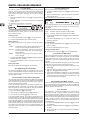
4. BPM and Effects section
== Turn the CONSOLE SETUP knob [51] to change the TIME
parameter.
== Turn the PARAMETER knob [45] to change the RANGE
parameter.
Exiting the Ultramizer setup:
== Press the ESC push button [52] to exit the Ultramizer setup.
3.5.2 Loading and saving user settings
A great advantage of a digital mixer is the possibility to store
entire mixer settings in order to recall them later on at the flick of
a switch. Big studio consoles refer to this function as “Snapshot”
because all settings are captured (as with a snapshot). This lets
you adjust the mixer to your way of working and recall settings
you made at any time.
Just imagine, a club has the DDM4000 which is being used
by several DJs. Each DJ has stored personal EQ settings, kill
frequencies, Ultramizer and Effect settings, so that when it is his
or her turn, the preferred settings can be recalled immediately.
The other way around, a guest DJ, who is not accustomed to the
DDM4000, is able to take off without having to adjust any settings
in advance.
Fig. 4.1: BPM and Effects section
The BPM and Effects section in the middle of the mixer can either be used for the stereo channels or the master signal. Both
processors can also be combined to be used as dual effect for
individual channels. What’s more, both Microphone channel and
Sampler feature their own effect processors, which are described
in individual chapters (Chapter 3.3.1 and Chapter 5.4).
Display:
++ After switching on the device, the last selected preset
is loaded.
Loading user settings:
1) P
ress the LOAD push button [35]. The LOAD push button
flashes.
“User Setup” appears on the screen, displaying the preset list:
The display shows the following information:
A
B
C
2) Turn the left PARAMETER knob [45] to select a user setting
(or the factory preset).
3) Press the PARAMETER knob again to load the user setting.
D
Shows the effect type and the parameter values.
Shows the calculated speed in BPM (Beats Per Minute).
It also gives information on the signal assignment and the
Tap function.
This section shows the BPM-synchronized effect parameters
as beats on the right side. On the left, you see the activity
of the Kill function in the effect path.
This information refers to the Sampler and/or the MIDI Clock
(see Chapter 5).
Storing user settings:
1) Press the LOAD push button [35] to access User Setup with
its preset list.
2) Turn the CONSOLE SETUP knob [51] to select a memory
location.
3) Press the CONSOLE SETUP knob to store the user setting.
++ It is not possible to overwrite the factory preset.
Exiting User Setup:
== Press the LOAD push button [35] or the ESC push button
(52) to exit User Setup.
BPM and Effects section
17
DIGITAL PRO MIXER DDM4000
4.1 Effects section
4.1.3 Selecting an effect
Nine effect types are available. The effect table in Chapter 4.1.4
gives an overview of the possible effects and their adjustable
parameters.
1) Press the SELECT push button [46]. The display shows a list
of all types of effects.
Fig. 4.2: Effects section (here FX 1)
2) Turn the PARAMETER knob [45] to select the effect type.
3) Press the PARAMETER knob to load the effect type.
4.1.1 Selecting the signal source
To use an effect, you first have to assign the effect to a signal
source. This assignment also applies to the BPM Counter. Possible
input sources are as follows:
4.1.4 Effect descriptions
The following gives you a description of the available effects
and adjustable parameters. (BPM-synchronized parameters are
printed in italic.) The tables show you which controls are used to
adjust the parameters. Chapter 4.1.5 describes effect processing.
Chapter 4.1.6 gives you the information you need to know about
BPM-synchronized parameters.
FLANGER, PHASER, PAN:
INPUT 1 – INPUT 4:
MUSIC:
CHAIN:
Stereo channels 1 – 4.
Stereo sum signal (main signal).
CHAIN assigns the effect to the signal of
the other effects section, so that 2 effects
are triggered consecutively.
Selecting a signal for FX1:
1) Press the FX1 ASSIGN push button [43].
2) Turn the left PARAMETER knob [45] to select a signal source
from the list.
3) Press the left PARAMETER knob to confirm the selection.
Selecting a signal for FX2:
FLANGER: The flanger effect is achieved by frequency modulation. You are able to adjust the speed of the LFO (Low Frequency
Oscillator), the amount of the effect signal that is fed back to the
input (Feedback), the effect depth (Depth) and the degree of
phase shifting represented in rhythmical units (Phase). Use Fade
in case you want the flanger to complete its period of oscillation
after the effect has been turned off, to avoid an abrupt truncation
of the effect.
PHASER is similar to the flanger. In this case the modulation is
achieved through phase shifting. You can adjust the speed of the
LFO and the effect depth (Depth). Use Fade to determine if the
effect is to end abruptly or softly fade out.
PAN specified an effect which lets the signal move from the right
to the left side of the stereo image. This effect sounds the most
intensive when the DEPTH knob is turned right up. LFO adjusts
the speed of the panning and Depth adjusts the effect depth.
1) Press the FX2 ASSIGN push button [43].
2) Turn the right PARAMETER knob [45] to select a signal source
from the list.
3) Press the right PARAMETER knob to confirm the selection.
4.1.2 Activating an effect
1) Press the FX ON push button [42] to activate the effect. Both
the FX ON push button and the EFFECT/BAND push button
[46] – [48] flash.
2) Turn the DEPTH knob slowly to the right until you hear the
effect as is intended.
Kill function on the effect path:
A specially effective way of alienation is to remove individual
frequency bands from the effect processing. There are three additional Kill switches that are found on the signal path leading to
the effects unit. The EFFECT/BAND push buttons of the activated
effect flash blue corresponding to the frequency bands that are
active. By pressing the push buttons you are able to "kill" the frequency bands. And the display shows the Kill function’s status.
== Press one of the EFFECT/BAND push buttons ([46], [47],
[48]) while the effect is active. The push-button LED of the
deactivated band goes out.
18
Tab. 4.1: Effect parameters for Flanger, Phaser and Panning
DELAY, ECHO:
DELAY is a signal delay. The delay time (Time) can by synchronized with the BPM Counter. A simple delay (Simple) and the
3-Pong Delay, which spreads the delays across the whole stereo
image, are available.
ECHO is similar to the delay. The only difference is that the
delayed signal is repeated several times. Use Feedback to specify the number of times that the delay is to be repeated. Fade
determines if the echo is to fade out (On) or not (Off) when the
effect is turned off.
BPM and Effects section
DIGITAL PRO MIXER DDM4000
Tab. 4.2: Effect parameters for Delay and Echo
PITCHER, BITCRUSHER:
PITCHER changes the pitch of the music without changing the
tempo. Shift adjusts the pitch.
BITCRUSHER simulates a decrease in the digital resolution. From
soft lo-fi settings to toy sounds, everything is possible.
Tab. 4.5: Effect parameters for Filter
4.1.5 Editing effects
As already mentioned in the previous chapter, each effect has
up to five parameters (depending on the effect type) with which
you can adjust the effect. In each case it is possible to adjust one
parameter by using the BEAT push buttons. In most cases, this
is the BPM-synchronized parameter.
Effect parameters:
1) Press the PARAMETER push button [47] to select a parameter. This only works when the effect is deactivated (the FX ON
push button does not flash).
Tab. 4.3: Effect parameters for Pitch and Bitcrusher
2) Alternatively, press the PARAMETER knob [45] to select a
parameter.
3) Change the parameter value by turning the PARAMETER
knob [45].
REVERB:
REVERB is a reverberation effect. Eight different reverb room simulations are available. When Fade is activated, the reverberation
decays and is not truncated in case the effect is turned off.
Ambient is a very short reverb which lets you virtually hear the
walls of the room.
Box delivers a spatial impression without long reflections.
Cathedral: The long and dense reverb of a big cathedral, ideal
for slow tracks.
4) To switch to the next parameter, press PARAMETER [45] or
[47] again.
Dry / Wet mix:
== Turn the MIX knob [44] slowly to the right to mix the effect
(Wet) to the original signal (Dry).
4.1.6 BPM-synchronized effect parameters
Chamber produces the short reverb of a small room.
Some of the effect sound especially interesting when time-related
parameters respond to the rhythm of the music. The DDM4000
supports editable, BPM-synchronized parameters.
Editing BPM-synchronized parameters:
Chorus: A thick, warm reverberation which is shorter than that
of Cathedral.
1) Make sure that the BPM Counter calculates the correct value
(if applicable, enter manually with TAP, see Chapter 4.2).
Concert simulates the well-defined reverb of a big concert hall.
2) Change the parameter step-by-step with the BEAT push buttons [49]. The selected value appears on the display.
Cavern: An intensive, high-frequency-dominant reverb based on
a cave with rocky walls.
Echo: A thick, short reverb with a longer pre-delay.
Delay, Echo:
For the delay and echo effect, you can edit the delay time in musical
units. The number of beats is displayed:
Tab. 4.4: Effect parameters for Reverb
FILTER:
FILTER is an effect which is typically associated with synthesizer
music. Three types of filters are available: Band Pass, Low Pass
and High Pass. Resonance is used to increase the level of the
filter frequency which makes the effect sound more intensive. In
LFO Mode, the filter frequency is controlled by an LFO. Manual
Mode lets you control the filter frequency with the DEPTH knob
[44].
Fig. 4.3: Beats and note values for delay and echo
A rhythmical representation of the whole looks like this (showing
a selection of several beats):
BPM and Effects section
19
DIGITAL PRO MIXER DDM4000
4.2 BPM Counter
The Auto BPM Counter is automatically able to convert the tempo
of the track being played into BPM (Beats Per Minute). The detected BPM values are the basis for all time-related effect parameters
and for the recording duration of the sampler. The BPM can be
detected in two different ways: manually and automatically. In both
cases, the current BPM is shown in Section B of the display.
Automatically detecting beats with AUTO BPM:
The BPM Counter detects the tempo of the signal source assigned to the Effect section. The signal source is shown in the BPM
section of the display. (Assigning the signal source to the BPM/
Effect section is described in Chapter 4.1.1.)
Fig. 4.4: Rhythmically represented delay parameter
Flanger, Phaser, Pan, Filter:
For the filter effect, the BPM synchronization is only possible in
LFO Mode. You can adjust the speed of the modulation
(LFO speed). The values 1 – 32 correspond to the number of beats
that are needed for one oscillation period:
1) Make sure that “Auto BPM” is activated. When active, the
AUTO BPM push button [50] shines yellow and the BPM
indicator flashes on the display.
++ Should Tap Mode be active (AUTO BPM push button
shines blue), press the AUTO BPM push button longer
than one second to activate Auto BPM.
2) Now the BPM Counter determines the BPM value of the played
signal. It is constantly brought up to date to be able to respond
immediately to any tempo changes.
Manually detecting beats with TAP:
1) Make sure that Tap Mode is activated. When active, the AUTO
BPM/TAP push button [50] shines blue and the BPM indicator
shows “Manual.”
Fig. 4.5: Beats and note values for modulation effects
The following picture results from the musical context:
2) Tap the TAP push button [50] (at least 2x) in the rhythm of the
music, which results in a constant BPM value. Here’s a tip:
while tapping, listen in on the signal using the headphones.
++ Should Auto BPM be active (AUTO BPM push button
shines yellow), go to Step 2. When tapping the tempo,
Manual Mode is automatically activated.
3) The BPM value can always be readjusted by tapping over
and over again.
++ The Auto BPM is always active when the device is
turned on.
++ Without a music signal (or one which is too quiet), the
BPM value flashes on the display. In addition, the message “Low Level” appears on the display. The BPM value
also flashes when the beat cannot be clearly identified
(message “Uncertain”).
Fig. 4.6: LFO parameter, represented in beats and bars
4.1.7 FX Setup
FX Setup lets you specify the crossover frequencies between the
individual bands of the EFFECT/BAND push buttons [46] – [48]
(Kill function on the effect path, see Chapter 4.1.2). This is individually done for both effect devices.
Adjustable parameters:
FX1 LOW / FX2 LOW:
Crossover frequency between LOW
and MID.
FX1 HIGH / FX2 HIGH: Crossover frequency between MID
and HIGH.
1) Press the left or right PARAMETER knob [45] to select the
parameter for FX1 and FX2.
2) Turn the left or right PARAMETER knob to change the value
of the selected value.
20
BPM and Effects section
DIGITAL PRO MIXER DDM4000
5. Sampler
4.3 MIDI Clock
The MIDI Clock is used as a time reference for the Bounce function. In addition, the MIDI Clock is given out at the MIDI output.
This allows you to synchronize external devices, which are able
to receive MIDI Clock (such as drum machines and grooveboxes)
with the DDM4000.
Fig. 4.7: BPM section
== Press the push button [52] to start and stop the MIDI Clock.
You can adjust the tempo of the MIDI Clock. Alternatively, the
MIDI Clock can also be synchronized with one of the two BPM
Counters:
Fig. 5.1: Sampler section
MIDI BPM:
When in MIDI BPM Mode, “MIDI BPM” appears in the middle of
the display below the BPM indicator of the MIDI Clock. Adjust the
tempo by turning the CONSOLE SETUP knob [51]. It is possible
to make bigger value jumps by pressing and simultaneously
turning the knob.
FX1/FX2 BPM:
To transmit the detected tempo of the BPM Counter to the MIDI
Clock, press one of the ADJUST push buttons [53]. By pressing the
left BEAT push button, the MIDI Clock adopts the tempo of the left
BPM Counter. By pressing the right BEAT push button, the MIDI
Clock adopts the tempo of the right BPM Counter. The assignment
is indicated by displaying “FX1 BPM” or “FX2 BPM.”
Cancel the assignment by turning the CONSOLE SETUP knob to
specify your own tempo.
The tempo of the MIDI BPM can also be transmitted to the BPM
Counter. Hold the left or right ADJUST push button [53] (or both
at the same time) while selecting the tempo with the CONSOLE
SETUP knob [51]. This function is useful when assigning effects
to a channel which is configured as MIDI controller so that the
Auto BPM function does not work.
A sampler is a device used to record and play back audio signals.
The DDM4000’s sampler lets you record two tracks which then
can be played back. These tracks are single short sequences,
vocal phrases, rhythmic loops or even longer song passages. Any
audio signal fed to the mixer can be used as signal source, usually
found on the stereo channels, the Microphone channel and the
stereo sum. The maximum recording duration is 32 seconds. The
samples can be played back in various ways (as infinite loop/loop,
one time, forward, reverse).
5.1 Recording samples
1) Select a signal source with the REC SOURCE push buttons
[56]. The signal source is indicated above the REC SOURCE
LEDs:
Signal sources:
1, 2, 3, 4:
MIC:
MST:
Stereo channel 1, 2, 3 or 4
Microphone channel
Master (stereo sum)
2) Use the SAMPLE LENGTH push buttons [58] to specify the
recording duration you want. The length ranges between 1
and 16 beats or “?” (infinite recording).
++ The actual recording time depends either on the detected BPM tempo or the MIDI Clock. The Sampler synchronizes with the BPM Counter provided that the BPM
Counter is assigned to Channel 1, Channel 2 or Master.
When this is not the case, the Sampler is synchronized
with the MIDI Clock.
3) Use BANK ASSIGN [60] to select the memory bank. The
MODE push button [61] of the selected bank lights up yellow
to indicate its readiness to record.
4) Start the recording by using the RECORD/IN push button
[59].
Sampler
21
DIGITAL PRO MIXER DDM4000
5) The recording stops after the number of beats specified
beforehand.
6) Alternatively, stop the infinite recording (?) by pressing the
PLAY/OUT push button [45] or by pressing the REC push
button again.
++ The recoding duration of infinite recording (?) is specified by pressing the RECORD/IN push button [59] and
the PLAY/OUT push button [62]. In case Loop Mode is
activated at the same time, the sampler immediately
switches to playback by pressing the PLAY/OUT push
button.
5.2.3 Crossfader start
The Crossfader Start function lets you start the Sampler playback
with the crossfader. To be able to use this function, the Sampler
needs to be assigned to the crossfader.
1) Press the CF ASSIGN push button to route the Sampler to
one side of the crossfader (A or B).
2) Press CF START to activate Crossfader Start.
3) Press the BANK ASSIGN push button to select the bank that
is to be triggered by the crossfader.
Playback starts as soon as you move the crossfader to the side
assigned to the Sampler.
Memory:
The maximum recording time is 32 seconds for both banks. The
recording stops when the memory is full.
The length of a sample and the time left are shown on the Sampler
Mix display.
5.2 Playing back samples
1) Turn the VOLUME/MIX knob [55] to the center position.
5.2.4 Pitch Bend
The Pitch Bend function lets you change the speed of the sampler playback so that it can be aligned to the tracks being played.
There are two options:
1) Turn the BPM Adjust knob to permanently change the playback
speed of the sampler. Turn the knob to the right to speed up the
tempo and turn the knob to the left to slow down the tempo.
2) The ADJUST push buttons correspond to “Bend +” and “Bend
–.” Pressing one of these push buttons changes the speed
for a short while, in order for you to easily match the beat of
the playing track.
2) Press the PLAY push button to start playback.
3) Press PLAY a second time to stop playback.
5.2.1 Insert function
The sample playback is carried out in Mix Mode or Insert Mode.
In both cases the sample is played back on the channel selected
with REC SOURCE push buttons [56]. This can also be the stereo
sum. When playing back in Mix Mode, the sample is mixed to
the specific channel or is routed to the crossfader. When playing
back the sample in Insert Mode, the sample is crossfaded to the
assigned channel.
== When playing back in Mix Mode, the INSERT push button
[54] is not allowed to be pressed (push-button LED is off). The
VOLUME/MIX knob [55] is used as a channel fader (volume)
with which the sampler signal is mixed to the signal source.
The sampler signal is assigned to the crossfader by pressing
the CF ASSIGN push button [65]
== Press the INSERT push button [54] to play back the sample in
Insert Mode. The VOLUME/MIX knob [55] can now be used
as crossfading control (Mix). Turn the knob completely to the
right to hear only the sample during playback. When turning
the knob to the left, the sample fades into the signal source
of the selected channel.
5.3 Sampler effect
The sampler features a brake effect which simulates the braking of
the rotating platter until it comes to a halt. The length of the brakes
are available as 1-beat-, 4-beat- und 8-beat brakes.
1) Press the BANK ASSIGN push button to select the memory
bank that is to be processed with the effect.
2) Select the length of the brake by continuously pressing the
SELECT push button [64]. This is shown on the display.
3) Press the SMP FX ON push button [63] to activate the effect.
The push button flashes.
When the sampler comes to an end (SMP FX ON push button and
PLAY/OUT push button of the selected bank flash), the samplereffect needs to be deactivated by pressing SMP FX ON again in
order to restart playback.
4) Press the SMP FX ON push button to restart playback.
++ Assigning the crossfader to the Sampler is only possible
in Mix Mode. As soon as the CF ASSIGN push button
[65] is pressed, the Insert function is automatically
deactivated.
5.2.2 Reverse and Loop playback
Use the MODE push buttons [61] for Bank 1/2 to determine the
type of playback. Select the playback mode for each bank:
REVERSE:
1) Tap the MODE push button to switch to Reverse Mode. The
REVERSE LED lights up. By pressing PLAY, the sample is
played back in the reverse direction.
2) Tap the MODE push button again. The REVERSE LED goes
out. The sample is played back in the forward direction.
LOOP (infinite loop):
1) Press the MODE push button for approximately 1 second to
deactivate Loop Mode. The LOOP LED goes out. The sample
is played back as long the PLAY push button is pressed. This
type of playback is ideal for short inserts/samples.
2) Press the MODE push button again for approximately 1 second
to activate Loop Mode. The LOOP LED lights up. The sample
is played back as infinite loop by pressing PLAY.
22
Sampler
DIGITAL PRO MIXER DDM4000
6. Further settings
7. The DDM4000 as MIDI controller
6.1 Loading factory settings
1) Press the LOAD push button [35]. The display switches to
“User Setup”. The LOAD push button lights up.
2) Select the factory preset by turning and pressing the left
PARAMETER knob [45].
The DDM4000 can be used to control DJ or sequencer software
applications by converting individual mixer sections on the mixer to
MIDI controllers and assigning these to defined software functions.
The MIDI interface [76] is used to transmit the data. To connect to
the mixer, the computer requires a MIDI interface, which can be
purchased as USB alternative for a very reasonable price.
3) Press the left PARAMETER knob to confirm the selection.
4) Press the LOAD push button [35] or the ESC push button
[52] to exit User Setup.
6.2 Output Setup
USB-MIDI Interface*
1) Press the CONSOLE SETUP knob [51] for approximately 2
seconds.
2) Select “Output Setup” by turning and pressing the CONSOLE
SETUP knob. Output Setup appears on the display:
OUT B
MONO
OFF
ON
OUTPUT
SETUP
MODE
FULL-FREQ
CROSSOVER
SUB-OUT
FREQ
55Hz
GAIN
-3.0dB
TAPE/
S/PDIF
GAIN
-6.0dB
In Output Setup, you make the following settings:
Mono:
Use this function to switch the OUT B outputs [74] to mono.
1) Turn the left PARAMETER knob [45] to select OFF or ON.
2) Press the left PARAMETER knob to confirm.
MIDI IN/OUT/THRU
Mode:
You can use Output A [73] together with the Subwoofer output,
in which case the bass frequencies are separated from the Main
output (crossover function).
FULL-FREQ:
CROSSOVER:
MAIN OUT A [73] emits the entire frequency
spectrum (including the bass signal). The
Subwoofer output gives out the subwoofer
signal.
The Subwoofer output gives out the subwoofer
signal. MAIN OUT A emits frequencies that are
above the crossover frequency.
1) Turn the CONSOLE SETUP knob [51] to select the mode
(FULL-FREQ, CROSSOVER).
2) Press the CONSOLE SETUP knob to confirm.
Sub Out:
The following are used to adjust the crossover frequency and
output level of the subwoofer output.
FREQ:
GAIN:
Crossover frequency between SUB OUT and MAIN
OUT
Output level of SUB OUT
TAPE / S/PDIF:
The levels of both Tape and S/PDIF outputs can be adjusted
individually.
1) Press the right PARAMETER knob to select the parameter
(FREQ, GAIN or TAPE/ S/PDIF GAIN).
* not included
Fig. 7.1: Connecting the DDM4000 to a computer
7.1 MIDI protocol
The MIDI format is used for the data transmission. Knobs and
faders send Control Change messages (CC), and push buttons
send Note messages (see Table 10.2). Access the software
settings to assign mixer controls to software functions. Most
software applications offer a learn function to make the assigning
even easier.
The MIDI transmission also works in the opposite direction. Basically, it is confined to controlling the LEDs, so that a switching
status in the software application can also be shown on the
DDM4000. In this case the DDM4000 receives CC messages
from the computer. Each LED of the DDM4000 is assigned to
a CC number (see Table 10.3). Sending the value 0 makes the
LED go out, but sending the value 1 (or any higher value) turns
on the LED.
7.2 Common MIDI settings
The MIDI settings are made on the MIDI Setup page.
1) P
ress the CONSOLE SETUP knob [51] for approximately 2
seconds.
2) S
elect “MIDI Settings” by turning and pressing the CONSOLE
SETUP knob. The MIDI Setup page appears on the display:
2) Turn the PARAMETER knob to change the value.
3) Press the ESC push button to exit Output Setup.
6.3 Adjusting display contrast
1) Press the LOAD push button [35]. User Setup appears on
the display.
2) Turn the right PARAMETER knob [45] to change the contrast.
3) Press the LOAD push button to exit User Setup.
This page allows you to make the following settings:
== Adjusting the MIDI channel (7.2.1)
== Sending a MIDI dump (7.2.2)
== Configuring the Microphone channel, Sampler and crossfader
as MIDI controller (7.3)
== Configuring stereo channels as MIDI controllers (7.4)
3) Press the ESC push button [52] to exit MIDI Setup.
++ Save the settings you made in a user preset (see Chapter 3.5.2 “Storing user settings”) in case you want the
settings to be active the next time you switch on the
device.
The DDM4000 as MIDI controller
23
DIGITAL PRO MIXER DDM4000
8. Installation
7.2.1 Setting the MIDI channel
The following describe how to specify the MIDI channel on which
the DDM4000 is to send controller data. The receiving device
needs to be set to the same channel.
1) Open MIDI Setup (see Chapter 7.2).
2) Turn the left PARAMETER knob [45] to select the MIDI
channel.
3) Press the ESC push button [52] to exit MIDI Setup.
7.2.2 Sending a MIDI dump
The inputs and outputs of the BEHRINGER DDM4000 are RCA
connectors. The Headphone output is a stereo jack. The Microphone inputs are XLR connectors.
++ Make sure that only competent people install your
DDM4000. They must be sufficiently earthed during and
after the installation process. Otherwise, electrostatic
discharges may negatively affect the operating characteristics of your equipment.
A MIDI dump sends the values of current controller positions. As
a result, the DDM4000’s settings are aligned with the connected
computer.
1) Open MIDI Setup (see Chapter 7.2).
2) Press the left PARAMETER knob [45] to start the MIDI
dump. After sending the dump, the DDM4000 returns to
MIDI Setup.
3) Press the ESC push button [52] to exit MIDI Setup.
7.3 Configuring Microphone channel, Sampler
and crossfader as MIDI controller
The Microphone channel, the Sampler and the crossfader section
can individually be converted to MIDI controllers.
1) Open MIDI Setup (see Chapter 7.2).
2) Turn the CONSOLE SETUP knob [51] to select the mixer
section (MIC, SAMPLER, CROSSFADER) you want to use.
Fig. 8.1: XLR connector
3) Press the CONSOLE SETUP knob to confirm the selection.
The LEDs of the selected section go out.
4) Press the ESC push button [52] to exit MIDI Setup.
Particularities of the crossfader:
It is not possible to assign the stereo channels to the crossfader
when the crossfader section is defined as controller. The Assign
push buttons are inoperative. The routing behaves as if the crossfader is deactivated: the signals are directly fed to the mixer’s sum.
As for the Sampler, the CF Assign function and CF Start function
are also inoperative. As usual, the routing of the Sampler signal
is realized with the REC SOURCE push button.
7.4 Configuring stereo channels as
MIDI controller
Using the channel fader {8}, the EQ knobs {4} and the kill push
buttons {5} and {6} generates MIDI data when one of the 4 stereo
channels is configured as MIDI controller. The configured channel
is still able to play back music, however, the equalizer, the channel
fader and the CF Assign function are not active. In case an audio
signal is being fed to the selected channel, it is routed to the mixer’s
sum without being processed and at full volume level. Simply mute
the signal in case the audio function is not required.
1) Open MIDI Setup (see Chapter 7.2).
2) Turn the right PARAMETER knob [45] to select the stereo
channel you want (and, if required, the Mute function).
3) Press the PARAMETER knob to confirm the selection. The
push-button LEDs of the selected channel go out.
++ Press the ESC push button [52] to exit MIDI Setup. Level
jumps can occur when activating or deactivating the
MIDI controller function in a stereo channel depending
on the position of the equalizer and fader! Turn the OUTPUT knob in the Main and Phones section completely
to the left before activating this function.
24
Installation
Fig. 8.2: 1/4" headphones connector
Fig. 8.3: RCA cable
DIGITAL PRO MIXER DDM4000
9. Specifications
AUDIO INPUTS
Mic 1/2 (XLR, electronically balanced)
Max. input level
-14 dBu
Input impedance
2 kΩ
Phono (RCA)
Max. input level
-18 dBu
Input impedance
47 kΩ
Line (RCA)
Max. input level
+30 dBu
Input impedance
15 kΩ
AUDIO OUTPUTS
OUT A (XLR, balanced)
Max. output level
+21 dBu
Output impedance
200 Ω
OUT A / OUT B / TAPE (RCA)
Max. output level
+21 dBu
Output impedance
100 Ω
Phones Out
S/PDIF max. 260 mW @ 100 Ω / 1 % THD
(coaxial, 16 bit, 44.1 kHz)
EQUALIZER
Stereo Low
-? dB/+12 dB
Stereo Mid -? dB/+12 dB
Stereo High
-? dB/+12 dB
Mic Low
-12 dB/+12 dB, Shelving
Mic Mid
-12 dB/+12 dB, Peak
Mic High
-12 dB/+12 dB, Shelving
DIGITAL EFFECTS PROCESSOR
DSP
2x Analog Devices Black Fin
AD/DA converter
24-bit Sigma-Delta/128-times oversampling/Cirrus
Sampling rate
44.1 kHz
LCD display 320 x 40 pixel
MIDI interface
5-pin DIN jacks In/Out/Thru
SYSTEM SPECIFICATIONS
Frequency response
Mic
25 Hz – 20 kHz, +0/-3 dB
Phono
20 Hz – 20 kHz, +0/-3 dB
Line
20 Hz – 20 kHz, +0/-3 dB
Signal-to-noise ratio
Mic
> 87 dB
Phono
> 83 dB
Line
> 102 dB
Distortion (THD)
< 0,009 % (Line – OUT A)
Crosstalk
< -80 dB / 1 kHz (Line)
POWER SUPPLY
Mains voltage / fuse
100 – 240 V~, 50/60 Hz
Power consumption
Mains connector
T 1 A H 250 V
max. 20 W
standard IEC receptacle
DIMENSIONS/WEIGHT
Dimensions (H x W x D)
approx. 4 1/3" x 12 3/5" x 15 1/2"
(110 mm x 320 mm x 392 mm)
Weight approx. 9.3 lbs. (4.2 kg)
BEHRINGER is constantly striving to maintain the highest professional standards.
As a result of these efforts, modifications may be made from time to time to existing
products without prior notice. Specifications and appearance may differ from those
listed or illustrated.
Specifications
25
DIGITAL PRO MIXER DDM4000
10. Appendix
*These parameters can be synchronized with BPM
Fig. 10.1: Overview of effect parameters
MIC
CH-1
CH-2
CH-3
CH-4
Sampler
MIC
CH-1
CH-2
CH-3
CH-4
Sampler
L R
L R
L R
L R
L R
L R
L R
L R
L R
L R
L R
L R
L
MASTER
MASTER
Fig. 10.2: Mixer routings
26
Appendix
R
DIGITAL PRO MIXER DDM4000
11. Warranty
§ 1 Other warranty rights and national law
1. This warranty does not exclude or limit the buyer’s statutory rights
provided by national law, in particular, any such rights against the
seller that arise from a legally effective purchase contract.
2. The warranty regulations mentioned herein are applicable unless
they constitute an infringement of national warranty law.
§ 2 Online registration
Please do remember to register your new BEHRINGER equipment right
after your purchase by visiting http://www.behringer.com and kindly
read the terms and conditions of our warranty carefully.
Registering your purchase and equipment with us helps us process
your repair claims quicker and more efficiently.
Thank you for your cooperation!
§ 3 Warranty
1. BEHRINGER (BEHRINGER International GmbH including all BEHRINGER subsidiaries, except BEHRINGER Japan) warrants the
mechanical and electronic components of this product to be free of
defects in material and workmanship for a period of one (1) year*
from the original date of purchase, in accordance with the warranty
regulations described below. If the product shows any defects within
the specified warranty period that are not excluded from this warranty as described under § 5, BEHRINGER shall, at its discretion, either
replace the product by providing a new or reconditioned product or
repair the product using suitable new or reconditioned parts. In the
case that other parts are used which constitute an improvement,
BEHRINGER may, at its discretion, charge the customer for the
additional cost of these parts. In case BEHRINGER decides to
replace the product, this warranty shall apply to the replacement
product for the remaining initial warranty period, i.e one year* from
the date of purchase of the initial product.
2. If the warranty claim proves to be justified, the product will be
returned to the user freight prepaid.
excluded from this warranty, in particular, if caused by improper
handling of the product by the user. This also applies to defects
caused by normal wear and tear, in particular, of faders, crossfaders, potentiometers, keys/buttons, tubes, guitar strings, illuminants
and similar parts.
4. Damage/defects caused by the following conditions are not covered
by this warranty:
== improper handling, neglect or failure to operate the unit in
compliance with the instructions given in BEHRINGER user
or service manuals.
== connection or operation of the unit in any way that does not
comply with the technical or safety regulations applicable in
the country where the product is used.
== damage/defects caused by force majeure or any other condition
that is beyond the control of BEHRINGER.
5. Any repair or opening of the unit carried out by unauthorized personnel (user included) will void the warranty.
6. If an inspection of the product by BEHRINGER shows that the
defect in question is not covered by the warranty, the inspection
costs are payable by the customer.
7. Products which do not meet the terms of this warranty will be repaired exclusively at the buyer’s expense. BEHRINGER will inform
the buyer of any such circumstance. If the buyer fails to submit a
written repair order within 6 weeks after notification, BEHRINGER
will return the unit. Costs for freight and packing will be invoiced
separately C.O.D. When the buyer has sent in a written repair order
such costs will also be invoiced separately.
§ 6 Warranty transferability
This warranty is extended exclusively to the original buyer (customer of
retail dealer) and is not transferable to anyone who may subsequently
purchase this product.
No other person (retail dealer, etc.) shall be entitled to give any warranty
promise on behalf of BEHRINGER.
§ 7 Claim for damages
3. Warranty claims other than those indicated above are expressly
excluded.
Failure of BEHRINGER to provide proper warranty service shall not
entitle the buyer to claim (consequential) damages.
§ 4 Return authorization number
In no event shall the liability of BEHRINGER exceed the invoiced
value of the product.
1. To obtain warranty service, the buyer (or his authorized dealer) must
call BEHRINGER during normal business hours BEFORE returning
the product. All inquiries must be accompanied by a description
of the problem. The buyer or his authorized dealer will receive a
return authorization number.
* Customers in the European Union please contact BEHRINGER Germany Support
for further details.
2. Subsequently, the product must be returned in its original shipping
carton, together with the return authorization number. The return
shipment address will be indicated by BEHRINGER.
3. Shipments without freight prepaid will not be accepted.
§ 5 Warranty regulations
1. Warranty services will be furnished only if the product is accompanied by a copy of the original retail dealer’s invoice. Any product
deemed eligible for repair or replacement under the terms of this
warranty will be repaired or replaced.
2. If the product needs to be modified or adapted in order to comply
with applicable technical or safety standards on a national or local
level, in any country which is not the country for which the product
was originally developed and manufactured, this modification/adaptation shall not be considered a defect in materials or workmanship.
The warranty does not cover any such modification/adaptation,
irrespective of whether it was carried out properly or not. Under the
terms of this warranty, BEHRINGER shall not be held responsible
for any cost resulting from such a modification/adaptation.
3. Free inspections and maintenance/repair work are expressly
Technical specifications and appearance are subject to change without notice. The information contained herein is correct at the time of printing. All trademarks (except BEHRINGER, the BEHRINGER logo, JUST LISTEN and DIGITAL PRO MIXER) mentioned belong to their respective owners and are not affiliated with BEHRINGER. BEHRINGER
accepts no liability for any loss which may be suffered by any person who relies either wholly or in part upon any description, photograph or statement contained herein. Colors
and specifications may vary slightly from product. Products are sold through our authorized dealers only. Distributors and dealers are not agents of BEHRINGER and have absolutely no authority to bind BEHRINGER by any express or implied undertaking or representation. No part of this manual may be reproduced or transmitted in any form or by any
means, electronic or mechanical, including photocopying and recording of any kind, for any purpose, without the express written permission of BEHRINGER International GmbH.
Mac is a trademark of Apple Computer, Inc., registered in the U.S. and other countries. Windows is a registered trademark of Microsoft Corporation in the United States and other
countries. ALL RIGHTS RESERVED.
(c) 2007 BEHRINGER International GmbH.
BEHRINGER International GmbH, Hanns-Martin-Schleyer-Str. 36-38, 47877 Willich-Muenchheide II, Germany.
Tel. +49 2154 9206 0, Fax +49 2154 9206 4903
Warranty
27