1
SPECIAL PROVISIONS ROUTE I-80 EB TRUCK WEIGH & INSPECTION STATION MILEPOST 0.833 TO 2.786 CONTRACT NO. 001998500 TOWNSHIP OF KNOWLTON AND HARDWICK, WARREN COUNTY FEDERAL PROJECT NO. IM-080-5(092) AUTHORIZATION OF CONTRACT The Contract is authorized by the provisions of Title 27 of the Revised Statutes of New Jersey and supplements thereto, and Title 23 of the United States Code - Highways. SPECIFICATIONS TO BE USED The 2007 Standard Specifications for Road and Bridge Construction, of the New Jersey Department of Transportation as amended herein will govern the construction of this Project and the execution of the Contract. These Special Provisions consist of the following: Pages 1 to 153 inclusive. General wage determinations issued under Davis-Bacon and related acts, published by US Department of Labor, may be obtained from the Davis-Bacon web site at http://www.access.gpo.gov/davisbacon/nj.html under the appropriate county, select the construction type heading: HIGHWAY. Pay the prevailing wage rates determined by the United States Secretary of Labor and the New Jersey Department of Labor. If the prevailing wage rate prescribed for any craft by the United States Secretary of Labor is not the same as the prevailing wage rate prescribed for that craft by the New Jersey Department of Labor, pay the higher rate. State wage rates may be obtained from the New Jersey Department of Labor & Workforce Development (Telephone: 609-292-2259) or by accessing the Department of Labor & Workforce Development‟s web site at http://lwd.dol.state.nj.us/labor/wagehour/wagehour_index.html The State wage rates in effect at the time of award are part of this Contract, pursuant to Chapter 150, Laws of 1963 (NJSA 34:11-56.25, et seq.). If an employee of the Contractor or subcontractor has been paid a rate of wages less than the prevailing wage, the Department may suspend the Work, and declare the Contractor in default. The following FHWA funded project Attachments that are located after Division 1000: 1. Required Contract Provisions, Federal-Aid Construction Contracts (Form FHWA-1273). 2. Standard Federal Equal Employment Opportunity Construction Contract Specifications (Executive Order 11246). 3. Notice of Requirement for Affirmative Action to Ensure Equal Employment Opportunity (Executive Order 11246). 4. State of New Jersey Equal Employment Opportunity for Contracts Funded by FHWA. 5. Emerging Small Business Enterprise Utilization Attachment, FHWA Funded Contracts. 6. Equal Employment Opportunity Special Provisions. 7. Special Contract Provisions for Investigating, Reporting, and Resolving Employment Discrimination and Sexual Harassment Complaints. ROUTE I-80 EB TRUCK WEIGH & INSPECTION STATION MILEPOST 0.833 TO 2.786 CONTRACT NO. 001998500 TOWNSHIP OF KNOWLTON AND HARDWICK, WARREN COUNTY PAGE 1 DIVISION 100 – GENERAL PROVISIONS SECTION 101 – GENERAL INFORMATION 101.03 TERMS THE FOLLOWING TERMS ARE CHANGED. Completion. (3) IS CHANGED TO: 3. the Contractor has satisfactorily executed and delivered to the RE all documents, including federal form FHWA-47 “Contractor‟s Statement of Materials and Labor” according to 23CFR 635, certifications, and proofs of compliance required by the Contract Documents, it being understood that the satisfactory execution and delivery of documents, certificates, and proofs of compliance is a requirement of the Contract. pavement structure. The combination of pavement, base courses, and when specified, a subbase course, placed on a subgrade to support the traffic load and distribute it to the roadbed (see Figure 101-1). These various courses are defined as follows: 1. pavement. One or more layers of specified material of designed thickness at the top of the pavement structure. 2. base course. One or more layers of specified material of designed thickness placed on the subgrade or subbase. 3. subbase. One or more layers of specified material of designed thickness placed on the subgrade. 101.04 INQUIRIES REGARDING THE PROJECT 1. Before Award of Contract. THE FIRST PARAGRAPH IS CHANGED TO: Submit inquiries and/or view other questions/answers by following the format prescribed on the project‟s electronic bidding web page. 2. After Award of Contract. North Region Mr. Carl F. Kneidinger, Regional Construction Engineer 200 Stierli Court Mt. Arlington, NJ 07856-1322 Telephone: 973-770-5025 SECTION 102 – BIDDING REQUIREMENTS AND CONDITIONS 102.02 BIDDER REGISTRATION AND DOWNLOADING OF THE PROPOSAL DOCUMENTS THE LAST SENTENCE OF THE FIRST PARAGRAPH IS CHANGED TO: The Bidder shall not alter or in any way change the software. 102.03 REVISIONS BEFORE SUBMITTING A BID THE SECOND PARAGRAPH IS CHANGED TO: ROUTE I-80 EB TRUCK WEIGH & INSPECTION STATION MILEPOST 0.833 TO 2.786 CONTRACT NO. 001998500 TOWNSHIP OF KNOWLTON AND HARDWICK, WARREN COUNTY PAGE 2 The Bidder shall acknowledge all addenda posted through the Department‟s website. The addenda acknowledgement folder is included in the Department‟s electronic bidding file. The Department has the right to reject the bid if the Bidder has not acknowledged all addenda posted. 102.04 EXAMINATION OF CONTRACT AND PROJECT LIMITS 1. Evaluation of Subsurface and Surface Conditions. THE FOLLOWING IS ADDED: ROUTE I-80 EB TRUCK WEIGH & INSPECTION STATION MILEPOST 0.833 TO 2.786 CONTRACT NO. 001998500 TOWNSHIP OF KNOWLTON AND HARDWICK, WARREN COUNTY PAGE 3 NEW JERSEY DEPARTMENT OF TRANSPORTATION PAVEMENT CORE RECORD PROJECT/ROUTE & SECTION: I-80 EB DRILLER: WARREN GEORGE, INC. INSPECTOR: BOBBY ISAAC, HALEY AND ALDRICH COUNTY/TOWNSHIP: KNOWLTON TONWSHIP, WARREN COUNTY DATE STARTED: AUGUST 28, 2008 CORE NUMBER DATE COMPLETED: AUGUST 28, 2008 1 2 3 4 5 I-80 I-80 I-80 I-80 I-80 E E E E E MILE POST (MP or Station) A 20+50 A 24+48 A 24+50 A 28+47 A 32+50 LANE NO. (Left to Right) SHLDR 2 SERVICE ROAD SERVICE ROAD SERVICE ROAD OUTSIDE - - - - 4 4 4 4 4 TOTAL CORE DEPTH (Inches) 17.5 17.2 12.0 15.0 16.5 CORE DRILLED TO 17.5 17.2 12.0 15.0 16.5 SURFACE TYPE (AC/PC) AC AC AC AC AC AC THICKNESS (Inches) 8.5 8.0 12.0 15.0 16.5 PC THICKNESS (Inches) 9.0 9.2 - - - ROUTE DIRECTION (N, E, S, W) SHOULDER (Inside or Outside) CORE DIAMETER (Inches) * Lane 1 is the left lane in the direction of travel. The pavement information shown herein was used by the Department for design and estimate purposes. ROUTE I-80 EB TRUCK WEIGH & INSPECTION STATION MILEPOST 0.833 TO 2.786 CONTRACT NO. 001998500 TOWNSHIP OF KNOWLTON AND HARDWICK, WARREN COUNTY PAGE 4 NEW JERSEY DEPARTMENT OF TRANSPORTATION PAVEMENT CORE RECORD PROJECT/ROUTE & SECTION: I-80 EB DRILLER: WARREN GEORGE, INC. INSPECTOR: BOBBY ISAAC, HALEY AND ALDRICH COUNTY/TOWNSHIP: KNOWLTON TONWSHIP, WARREN COUNTY DATE STARTED: AUGUST 28, 2008 CORE NUMBER DATE COMPLETED: AUGUST 28, 2008 6 7 8 9 10 I-80 I-80 I-80 I-80 I-80 E E E E E MILE POST (MP or Station) C 11+47 C 15+50 C 19+50 C 23+49 C 28+85 LANE NO. (Left to Right) SERVICE ROAD SERVICE ROAD SERVICE ROAD SERVICE ROAD 2 SHOULDER (Inside or Outside) - - - - - CORE DIAMETER (Inches) 4 4 4 4 4 TOTAL CORE DEPTH (Inches) 9.5 9.6 9.2 9.0 21.0 CORE DRILLED TO 9.5 9.6 9.2 9.0 21.0 SURFACE TYPE (AC/PC) PC PC PC PC AC AC THICKNESS (Inches) - - - - 10.0 PC THICKNESS (Inches) 9.5 9.6 9.2 9.0 11.0 ROUTE DIRECTION (N, E, S, W) * Lane 1 is the left lane in the direction of travel. The pavement information shown herein was used by the Department for design and estimate purposes. ROUTE I-80 EB TRUCK WEIGH & INSPECTION STATION MILEPOST 0.833 TO 2.786 CONTRACT NO. 001998500 TOWNSHIP OF KNOWLTON AND HARDWICK, WARREN COUNTY PAGE 5 NEW JERSEY DEPARTMENT OF TRANSPORTATION PAVEMENT CORE RECORD PROJECT/ROUTE & SECTION: I-80 EB DRILLER: WARREN GEORGE, INC. INSPECTOR: BOBBY ISAAC, HALEY AND ALDRICH COUNTY/TOWNSHIP: KNOWLTON TONWSHIP, WARREN COUNTY DATE STARTED: AUGUST 28, 2008 CORE NUMBER DATE COMPLETED: AUGUST 28, 2008 11 12 I-80 I-80 E E MILE POST (MP or Station) B 28+84 D 33+89 LANE NO. (Left to Right) SHLDR 2 OUTSIDE - 4 4 TOTAL CORE DEPTH (Inches) 13.0 19.5 CORE DRILLED TO 13.0 19.5 SURFACE TYPE (AC/PC) AC BOTH AC THICKNESS (Inches) 13.0 8.5 PC THICKNESS (Inches) - 11.0 ROUTE DIRECTION (N, E, S, W) SHOULDER (Inside or Outside) CORE DIAMETER (Inches) * Lane 1 is the left lane in the direction of travel. The pavement information shown herein was used by the Department for design and estimate purposes. ROUTE I-80 EB TRUCK WEIGH & INSPECTION STATION MILEPOST 0.833 TO 2.786 CONTRACT NO. 001998500 TOWNSHIP OF KNOWLTON AND HARDWICK, WARREN COUNTY PAGE 6 3. Existing Plans and As-Builts. Existing Plans and As-builts used are as follows: a. ROUTE 80, SECTION 1AJ Truck Weigh Station and Appurtenances, South of Interchange 3, Township of Knowlton, Warren County, July 1979 b. ROUTE 46 (1953) SECTION 1, Dunnfield to Columbia, GRADING, Pahaquarry and Knowlton Townships, Warren County, May 1952 c. ROUTE 46 (1953) SECTION 1B, Dunnfield to Columbia, PAVING, Pahaquarry and Knowlton Townships, Warren County, February 1953 d. ROUTE 80, SECTION 1AB, From Delaware River Toll Bridge to Vicinity of Route 94, WIDENING, RESURFACING AND SAFETY IMPROVEMENTS, Townships of Pahaquarry and Knowlton, Warren County, October 1976 SECTION 104 – SCOPE OF WORK 104.03.04 Contractual Notice THE SECOND PARAGRAPH IS CHANGED TO: Immediately provide written notice to the RE of a circumstance that is believed to be a change to the Contract. If notice is not provided on Contractual Notice (Form DC-161), include the following in the initial written notice: 1. 2. 3. 4. 5. A statement that this is a notice of a change. The date when the circumstances believed to be a change were discovered. A detailed and specific statement describing the nature and circumstances of the change. If the change will or could affect costs to the Department. If the change will or could affect Contract Time as specified in 108.11.01.C. In addition to the hard copy of the notice, email the notice to the RE. It is not necessary to attach listed documents to the email. SECTION 105 – CONTROL OF WORK 105.05 WORKING DRAWINGS THE SECOND PARAGRAPH IS CHANGED TO: Ensure that working drawing submissions also conform to the Department design manuals and other Department standards for the proposed work. Ensure that working drawings are signed and sealed by a Professional Engineer. After Award, the Department will provide additional formatting information, the number of copies required, and the designated design unit to which the Contractor shall submit working drawings. THE FOLLOWING IS ADDED IN TABLE 105.05 1- WORKING DRAWING SUBMISSION CATEGORY AT THE END OF THE APPROVED COLUMN: Static Scale Bridge (Beams and Deck Slab) 105.07.01 Working in the Vicinity of Utilities A. Initial Notice. THE FOLLOWING IS ADDED: Submit notice, with a copy to the RE, at least 10 days before beginning construction operations, to each of the following utilities: ROUTE I-80 EB TRUCK WEIGH & INSPECTION STATION MILEPOST 0.833 TO 2.786 CONTRACT NO. 001998500 TOWNSHIP OF KNOWLTON AND HARDWICK, WARREN COUNTY PAGE 7 UTILITY Electric Telephone B. COMPANY/AGENCY Jersey Central Power & Light 300 Madison Avenue Morristown, NJ 07962 Embarq Corporation 256 Paul Street Belvidere, NJ 07823 CONTACT Mr. Robert Soto (973)-401-8582 NOTE Mr. Rober O‟Connor (908)-735-3543 Locating Existing Facilities. THE FOLLOWING IS ADDED: C. 2. Bureau of Traffic Operations, North Region (TOCN) 670 River Drive Elmwood Park, NJ 07407-1347 Telephone: 201-797-3575 3. Bureau of Electrical Maintenance, North Region 200 Stierli Court Mt. Arlington, NJ 07856-1322 Telephone: 973-770-5065 Protection of Utilities. THE SECOND PARAGRAPH IS CHANGED TO: Protect and support existing Department electrical and ITS facilities and ensure that there is no interruption of service. Use hand tools only while working within two feet of the fiber optic network. At least 30 days before beginning the work, submit a plan to the RE for approval showing the method of support and protection. 105.07.02 Work Performed by Utilities THE FOLLOWING IS ADDED: Provide a written request to each Utility to perform their work in accordance with the following number of Days of Advance Notice: Company Name & Address Jersey Central Power & Light 300 Madison Avenue Morristown, NJ 07962 Embarq Corporation 256 Paul Street Belvidere, NJ 07823 Contact Person Number of Day Advance Notice Mr. Robert Soto 14 Mr. Robert O‟ Connor 56 Utility Work and Time Frames General Notes: 1. 2. 3. 4. 5. 6. Each Utility shall coordinate any work with all affected parties. All distances, stations, offsets and lengths on the utility plan are approximate. The State‟s Contractor shall provide the company with the notices called for in the schedules. The State‟s Contractor will coordinate with the Utility for utility access during conflicting construction activities and for immediate access in the case of an emergency. All work proposed should be performed within accepted rights of way and utility easements. The State‟s Contractor shall provide the Utility with survey control. The State‟s Contractor and the Utility shall jointly verify the location of the existing and proposed utilities prior to installation. ROUTE I-80 EB TRUCK WEIGH & INSPECTION STATION MILEPOST 0.833 TO 2.786 CONTRACT NO. 001998500 TOWNSHIP OF KNOWLTON AND HARDWICK, WARREN COUNTY PAGE 8 7. Utility shall be in charge of maintaining service or coordinating any temporary interruption of their utility services as may be required. 8. The State‟s Contractor shall coordinate the project work with all affected companies. Grading and Site clearing work will be performed by the State's Contractor prior to mobilization by the Utility. 9. Utility shall consider the traffic control and construction staging operations for implementation of utility work. Utility schedules are based on the project traffic control and staging plan for each utility mobilization. Utility service demands, field and weather conditions may alter these schedules. State‟s Contractor changes to the traffic control and staging plan may require re-establishing utility schedules. 10. Utility schedules are estimated time frames for the utility owner only and do not include work performed by other utility owners sharing joint facilities. 11. Where joint facilities are proposed, the Utility shall coordinate its work with the joint owners or users. 12. Existing facilities can only be removed after the relocated facilities have been installed and are in operation. Jersey Central Power & Light Work to be performed by the Utility Company: Station 54+40: Pole NJ399PQ - Install transformer, connect riser and wires to riser and wire installed by State‟s Contractor (as per plan drawings). Station 121+40: Pole KT-29 – Install two risers, two runs of conduit and required wires from Pole KT-29 to the meter cabinets, installed by State‟s Contractor. Connect incoming service to meters. Station 150+80: Pole KT-802 – Install riser, conduit and required wires from Pole KT-29 to the meter cabinets, installed by State‟s Contractor. Connect incoming service to meters. Schedule: The company requires 14 days notice prior to commencing their work and estimates 4 weeks to complete construction of all items indicated above. Embarq Corporation Work to be performed by the Utility Company: Disconnect existing telephone service to the existing modular building prior its removal. Connect new telephone service to the proposed building. Schedule: The company requires 56 days notice prior to commencing their work and estimates 1 week to complete construction of each work item indicated above. SECTION 107 – LEGAL RELATIONS 107.04 NEW JERSEY CONTRACTUAL LIABILITY ACT THE FOURTH PARAGRAPH IS CHANGED TO: For purposes of determining the date of “completion of the contract” pursuant to N.J.S.A. 59:13-5, “completion of the contract” occurs on the date that the Contractor provides written notice to the Department of Acceptance or conditional Acceptance of the Proposed Final Certificate or the 30th day after the Department issues the Proposed Final Certificate, whichever event occurs first. ROUTE I-80 EB TRUCK WEIGH & INSPECTION STATION MILEPOST 0.833 TO 2.786 CONTRACT NO. 001998500 TOWNSHIP OF KNOWLTON AND HARDWICK, WARREN COUNTY PAGE 9 107.09 INDEPENDENT CONTRACTOR THE SECOND SENTENCE IS CHANGED TO: It shall neither hold itself out as, nor claim to be, an officer or employee of the Department by reason hereof. 107.12.01 Satisfying the Notice Requirements THE FOLLOWING IS ADDED TO THE SECOND PARAGRAPH: Upon request, provide the RE with 3 copies of all documentation submitted in support of the claim. 107.12.02 Steps 3. Step III, Claims Committee. THE SECOND PARAGRAPH IS CHANGED TO: The Claims Committee will not review a claim or combination of claims valued less than $250,000 until after the receipt of conditional release as specified in 109.11. If the Contract is 75 percent complete or greater as measured by Contract Time or Total Adjusted Contract Price, the Claims Committee will not review a claim or combination of claims valued more than $250,000 until after receipt of conditional release as specified in 109.11. If the Claims Committee does not review a claim or combination of claims before Completion, the Claims Committee will review the claim or combination of claims at a single session of the Claims Committee after the receipt of the conditional release as specified in 109.11 and all claims have been reviewed at Steps I and II of the Claims Resolution Process. When reviewing a combination of claims, the Claims Committee will not review any individual claim valued less than $20,000. SECTION 108 – PROSECUTION AND COMPLETION 108.01 SUBCONTRACTING 1. Values and Quantities. THE FOLLOWING IS ADDED: Specialty Items are as listed below: Above ground highway lighting items. Above ground sign lighting items. Above and below bridge deck lighting items. Electrical wire items. ITS items, except for foundations, standards, and junction boxes. Commercial Vehicle Inspection Building Control Building THE THIRD PARAGRAPH IS CHANGED TO: If a partial quantity of work for a unit price Item is subcontracted, the Department will determine the value of the work subcontracted by multiplying the price of the Item by the quantity of units to be performed by the subcontractor. ROUTE I-80 EB TRUCK WEIGH & INSPECTION STATION MILEPOST 0.833 TO 2.786 CONTRACT NO. 001998500 TOWNSHIP OF KNOWLTON AND HARDWICK, WARREN COUNTY PAGE 10 THE FOURTH PARAGRAPH IS CHANGED TO: If only a portion of work of an Item is subcontracted, the Department will determine the value of work subcontracted based on the value of the work subcontracted as indicated in the subcontract agreement and as shown in a breakdown of cost submitted by the Contractor. 108.02 COMMENCEMENT OF WORK THE SUBPART 4 IN THE FIRST PARAGRAPH IS CHANGED TO: 4. Progress schedule as specified in 153.03 108.08 LANE OCCUPANCY CHARGES THE SECOND PARAGRAPH IS CHANGED TO: The RE will keep record of each occurrence as well as the cumulative amount of time that a lane is kept closed beyond the lane closure schedule and provide the record to the Contractor. The Department will calculate the lane occupancy charge by multiplying the length of time of the delayed opening, in minutes, by the rate of $10 per minute per lane, unless otherwise specified in the Special Provisions. The total amount per day for the lane occupancy charge that the Department will collect will not exceed $10,000.00. THE FOLLOWING IS ADDED: The rate to calculate the Lane Occupancy Charge is as follows: Description Overrun of “Single Lane Maintained” Time Limits Rate $80/minute 108.10 CONTRACT TIME A. Complete all work required for Substantial Completion on or before September 5, 2012. B. Achieve Completion on or before November 5, 2012. 108.19 COMPLETION AND ACCEPTANCE THE FOLLOWING IS ADDED: No Incentive Payment for Early Completion is specified for this project. 108.20 LIQUIDATED DAMAGES THE FOLLOWING IS ADDED: Liquidated damages are as follows: A. For each day that the Contractor fails to complete the work as specified in Subpart A of Subsection 108.10 of these Special Provisions, for Substantial Completion, the Department will assess liquidated damages in the amount of $4000. C. For each day that the Contractor fails to achieve Completion as specified in Subpart C of Subsection 108.10 of these Special Provisions, the Department will assess liquidated damages in the amount of $1000. THE FOLLOWING IS ADDED: When the Contractor may be subjected to more than one rate of liquidated damages established in this Section, the Department will assess liquidated damages at the higher rate. ROUTE I-80 EB TRUCK WEIGH & INSPECTION STATION MILEPOST 0.833 TO 2.786 CONTRACT NO. 001998500 TOWNSHIP OF KNOWLTON AND HARDWICK, WARREN COUNTY PAGE 11 SECTION 109 - MEASUREMENT AND PAYMENT 109.01 MEASUREMENT OF QUANTITIES THE SECOND PARAGRAPH IS CHANGED TO: The Department will designate Items as Measured Items or as Proposal Items by having a suffix of M or P in the Item number respectively. The Department will measure quantities of Measured Items for payment. 109.02 SCOPE OF PAYMENT THE THIRD SENTENCE OF THE FIRST PARAGRAPH IS CHANGED TO: The Department will not make additional or separate payment for work or portion of work unless specifically provided for in the “Measurement and Payment” Subsection. ROUTE I-80 EB TRUCK WEIGH & INSPECTION STATION MILEPOST 0.833 TO 2.786 CONTRACT NO. 001998500 TOWNSHIP OF KNOWLTON AND HARDWICK, WARREN COUNTY PAGE 12 DIVISION 150 – CONTRACT REQUIREMENTS SECTION 152 – INSURANCE 152.03.01 Owner’s and Contractor’s Protective Liability Insurance A. Policy Requirements. THE FOURTH SENTENCE OF THE FIRST PARAGRAPH IS CHANGED TO: Ensure that policies are underwritten by companies with a current A.M. Best rating of A- with a Financial Size Category of VII or better. B. Types 1. Comprehensive General Liability Insurance. THE FOLLOWING IS ADDED: Ensure the policy names JCP&L, its officers, employees and agents as additional insured. 2. Comprehensive Automobile Liability Insurance. THE FOLLOWING IS ADDED: Ensure the policy names JCP&L, its officers, employees and agents as additional insured. 5. Excess Liability Insurance. THE FOLLOWING IS ADDED: Ensure the policy names JCP&L, its officers, employees and agents as additional insured. 6. Marine Liability Insurance. THE FOLLOWING IS ADDED: Ensure the policy names JCP&L, its officers, employees and agents as additional insured. SECTION 153 – PROGRESS SCHEDULE 153.03.01 CPM Progress Schedule THE THIRD PARAGRAPH IS CHANGED TO: The Contractor may propose alternate staging. Ensure that proposed alternate staging does not interfere with work done by Others without written concurrence from the affected Others. The Department may reject the proposed alternate staging if it causes an increase to the cost of work done by Others. The Contractor is responsible for the cost of changes or additional work required as a result of completing the work according to the proposed alternate staging. 153.03.02 CPM Progress Schedule Updates THE LAST PARAGRAPH IS CHANGED TO: If the project falls behind schedule for nonexcusable delays, so that the schedule indicates that the Work will not be completed by the Completion date, as specified in 108.10, take the necessary steps to improve progress. Under such circumstances, the RE may direct the Contractor to increase the number of shifts, begin overtime operations, work extra days including weekends and holidays, and supplement its construction plant. Furthermore, the RE may require the ROUTE I-80 EB TRUCK WEIGH & INSPECTION STATION MILEPOST 0.833 TO 2.786 CONTRACT NO. 001998500 TOWNSHIP OF KNOWLTON AND HARDWICK, WARREN COUNTY PAGE 13 Contractor to submit for approval a recovery schedule showing how the Contractor proposes to meet the directed acceleration. 153.04 MEASUREMENT AND PAYMENT THE THIRD PARAGRAPH IS CHANGED TO: If the Contractor‟s CPM Progress Schedule update is not approved by the date of the progress meeting for the following update, the Department will assess liquidated damages to recover the Department‟s increased administrative costs. The Department will assess damages for each delinquent update as follows: SECTION 155 – CONSTRUCTION FIELD OFFICE 155.03.01 Field Office 4. Communication Equipment. a. Telephones. Provide 3 cordless phones with auto-switching. c. Cell Phones. Provide 4 cellular phones. Ensure the cellular phone plan provides for unlimited mobile to mobile in-network usage, unlimited push-to-talk/ walkie-talkie usage and an anticipated monthly usage of 900 any-time minutes for each phone. Ensure the phones are on the same plan. Ensure the cellular phone plan has a home rate with no roaming charges within the state. Ensure each cellular phone has the following features: 1. 2. 3. 4. 5. d. Push to Talk / Walkie-Talkie capable Camera with 1 megapixel picture capability Battery life capable of 180 minutes of continuous use and 72 hours of standby use Equipped with a hands-free headset Base charger and car charger Computer System. Provide a computer system meeting the following requirements: 2 computer configurations each meeting the following: 1. Equipped with an Intel Pentium IV processor with Hyper Threading technology having a clock speed of 3.5 GHz or faster, 2 GB RAM, 512 MB Video RAM, 200 Gigabyte hard drive designated as drive C, one DVD (+/-) Writer Drive, one CD-R Recordable Drive. Ensure the system is USB 2.0 compatible and has at least two front USB ports. 2. Wired Router with appropriate number of ports and cables and a print server. Ensure there is at least one Ethernet switch. 3. High-speed broad band connection and service with a minimum speed of 3 Megabytes per second (mbps) with dynamic IP address for the duration of the project. 4. 19 inch or larger Flat Screen LCD monitor with tilt/swivel capabilities. 5. 250 Megabyte or larger Zip Drive internal or external with backup software for MS-Windows and DOS, and fifteen corresponding formatted data cartridges corresponding to the tape drive size. 6. 1 Flatbed USB version 2.0 or greater Color Scanner with automatic document feed. 7. Uninterruptible power supply (UPS). 8. Surge protector for the entire computer configuration to be used in conjunction with the UPS. 9. 2 computer workstations, chair, printer stand, and/or table having both appropriate surface and chair height. 10. One can of compressed air and screen cleaning solution every other month of the duration of the contract. Ensure one computer has a 56K baud data/fax modem. If more than one computer configuration is specified, provide one network interface card for the base computer configuration and hardwire connections between computer configurations as directed by the RE. ROUTE I-80 EB TRUCK WEIGH & INSPECTION STATION MILEPOST 0.833 TO 2.786 CONTRACT NO. 001998500 TOWNSHIP OF KNOWLTON AND HARDWICK, WARREN COUNTY PAGE 14 Also provide: 10 USB 3 GB Flash/Jump memory drives 25 CD-R 700 MB (or larger) recordable CD‟s compatible with the CD drive and 25 recordable DVD‟s. 1 CD/DVD Holder (each holds 50) 2 color laser printers and supplies as follows: 1. 2. HP PCL 5 emulation, with a minimum of 192 Megabytes of expanded memory, printer cable, and legal size paper tray . One set of printer ink cartridges every other month for the duration of the construction project for each printer. Software as follows: 1. 2. 3. 4. 5. 6. 7. Microsoft Windows, latest version with future upgrades for the duration of the entire project. Ensure 1 computer has a Microsoft Windows 32 Bit Operating System for ACES, Extra and Groupwise. Microsoft Office Professional, latest version. Norton‟s System Works for Windows, latest version, or compatible software package with future upgrades and latest virus patches. Anti-Virus software, latest version with monthly updates for the duration of the contract. Visio Professional Graphics Software for Windows, latest version Primavera Project Planner, latest version Adobe Acrobat Professional. Latest versions, for Scanner THE THIRD PARAGRAPH IS CHANGED TO: When the computer system is no longer required by the RE, the Department will remove and destroy the hard drive, and return the computer system to the Contractor. The Department will retain other data storage media. 6. Office Equipment. 2. 3. 7. 1 digital camera(s). Ensure each digital camera has auto-focus, with rechargeable batteries and charger, 256 MB memory card, USB Memory Card Reader compatible with camera and field office computer, 1.5 inch LCD monitor, 5 mega pixel resolution, 10 X optical zoom lens, built in flash, image stabilization, computer connections, and a carrying case 0 video camcorder(s). Ensure each video camcorder is a mini DVD camcorder with ___ optical zoom, 2" LCD monitor, USB 2.0 compatible and includes USB 2.0 connections. Inspection Equipment. 1. 2. 3. 4. 5. 5. 7. 8. 9. 10. 11. 12. 13. 14. 15. 2 Calculators with trigonometric capability 1 Date/ Received stamp and ink pad 1 Electronic Smart level, 4 foot 6 Carpenter rulers 1 Steel tape, 100 feet 1 Cloth tape, 100 feet 1 Illuminated measuring wheel 1 Plumb bob and cord 1 Line level and cord 1 Surface thermometer 1 Concrete thermometer 2 Digital infrared asphalt thermometer 0 Direct Tension Indicator (DTI) Feeler Gage, 0.005 inch 0 Sledge hammer, 8lb 1 Self leveling laser level with range of 100 feet and an accuracy of ¼ inch per 100 feet ROUTE I-80 EB TRUCK WEIGH & INSPECTION STATION MILEPOST 0.833 TO 2.786 CONTRACT NO. 001998500 TOWNSHIP OF KNOWLTON AND HARDWICK, WARREN COUNTY PAGE 15 16. 6 Hard hats - orange, reflectorized hard hats according to ANSI Z89.1 17. 6 Safety garments – orange, reflectorized, 360º high visibility safety garments according to ANSI/ISEA Class 3, Level 2 standards. To be replaced yearly for the duration of the contract. 18. 4 Sets of rain gear with reflective sheeting 19. 4 Sets of hearing protection with a Noise Reduction Rating of 22 dB 20. 4 Sets of eye protection according to ANSI Z87.1 21. 0 Sets of fall arrest equipment according to ANSI Z359.1 standards consisting of a full body harness, lanyard and anchor 22. 1 Light meter - capable of measuring the level of luminance in foot-candles 23. 2 Lantern flashlight, 6V with monthly battery replacements 24. 1 Digital Psychrometer. 25. 0 Chain Drag according to ASTM D4580-86 26. 1 Testing equipment and apparatus conforming to AASHTO T23, T119, T152. 27. 4 Hard Bound Daily Diaries, 5-1/2” x 8” minimum with one day per page. To be provided yearly for the duration of the contract. 28. 250 Legal size hanging folders. 29. 250 Legal size manila file folders – three tab. 155.03.03 Telephone Service THIS SUBPART IS CHANGED TO: Telephone service consists of monthly charges for telephone and cellular phones provided for the field office and materials field laboratory excluding set up charges. 155.04 MEASUREMENT AND PAYMENT THE THIRD PARAGRAPH IS CHANGED TO: The Department will make payment for TELEPHONE SERVICE for the actual costs of the charges as evidenced by paid bills submitted within 60 days of receipt from the service provider for telephone and cell phones. SECTION 156 – MATERIALS FIELD LABORATORY AND CURING FACILITY 156.03.05 Nuclear Density Gauge THE LAST PARAGRAPH IS CHANGED TO: Provide a nuclear density gauge for the exclusive use of the ME using one of the following methods: 1. 2. Purchase a nuclear density gauge under the Contractor‟s New Jersey Department of Environmental Protection (NJDEP) License or the Contractors United States Nuclear Regulatory Commission (USNRC) license. Lease a nuclear density gauge from a New Jersey Department of Environmental Protection (NJDEP) or United States Nuclear Regulatory Commission (USNRC) licensed third party on the Department‟s New Jersey Department of Environmental Protection (NJDEP) License. The Contractor is barred from purchasing gauges on the Department‟s New Jersey Department of Environmental Protection (NJDEP) license. Perform calibration and servicing of the gauge, other than routine wipe tests, every 24 months. The ME may direct additional calibrations, when necessary. Supply a replacement gauge for the Department‟s use during the calibration and servicing period. ROUTE I-80 EB TRUCK WEIGH & INSPECTION STATION MILEPOST 0.833 TO 2.786 CONTRACT NO. 001998500 TOWNSHIP OF KNOWLTON AND HARDWICK, WARREN COUNTY PAGE 16 SECTION 157 – CONSTRUCTION LAYOUT AND MONUMENTS 157.03.01 Construction Layout THE SEVENTH PARAGRAPH IS CHANGED TO: Provide the Utilities with the layout needed to install relocated utility facilities and coordinate the Work. Ensure that relocated facilities do not conflict with proposed construction, including High Voltage Proximity Act conflicts. SECTION 158 – SOIL EROSION AND SEDIMENT CONTROL AND WATER QUALITY CONTROL 158.03.02 SESC Measures 19. Oil-Only Emergency Spill Kit. THE SECOND SENTENCE OF THE FIRST PARAGRAPH IS CHANGED TO: Include Oil-only Emergency Spill Kit, Type 1 consisting of the following: SECTION 159 – TRAFFIC CONTROL 159.02.02 Equipment THE FOLLOWING IS ADDED TO THE LIST OF EQUIPMENT REFERENCES: Portable Variable Message Sign w/Remote Communication…….………………...……………………1001.04 Portable Trailer Mounted CCTV Camera Assembly……………….……………………………………1001.05 159.03.02 Traffic Control Devices 2. Construction Barrier Curb. THE LAST PARAGRAPH IS CHANGED TO: Provide top and side mounted flexible delineators on the construction barrier curb. For delineators located on the right side when facing in the direction of traffic, ensure that the retroreflective sheeting is white. For delineators located on the left side when facing in the direction of traffic, ensure that the retroreflective sheeting is yellow. Attach flexible delineators according to the manufacturer‟s recommendations. Starting at the beginning of the construction barrier curb section mount top delineators at 100-foot intervals on tangent sections, curves of radii greater than 1,910 feet, and at 50-foot intervals on curves of radii of 1,910 feet or less. Mount side delineators at the lead end of each barrier segment with the top of the delineator 3 inches from the top of the barrier. 6. Traffic Control Truck with Mounted Crash Cushions. THE LAST SENTENCE IS CHANGED TO: Submit drawings to the RE detailing the manner of securing the ballast, signed and sealed by a Professional Engineer, certifying that it is capable of withstanding the impact forces for which the impact attenuator is rated. THE FOLLOWING IS ADDED TO THE SECOND PARAGRAPH: 8. Portable Variable Message Sign w/Remote Communication (PVMSRC). Place the PVMSRC at the location directed by the RE. Ensure that a designated representative familiar with the operation and programming of the unit is available on the Project for On-Site Configuration. Only display messages authorized by the Department for the Project and make the signs available for use remotely from the Traffic Operation center (TOC) specified in 105.07.01.B. Repair or replace malfunctioning PVMSRC within 12 hours of notification by the RE. Provide a broadband cellular telephone service plan with unlimited data service on an IP based packet network for the intended operational and functional requirements of the PVMSRC. Ensure that the PVMSRC ROUTE I-80 EB TRUCK WEIGH & INSPECTION STATION MILEPOST 0.833 TO 2.786 CONTRACT NO. 001998500 TOWNSHIP OF KNOWLTON AND HARDWICK, WARREN COUNTY PAGE 17 has remote operation capability from the specified TOC using the Department‟s current DMS control software at the time of deployment. Provide for one week of testing by the TOC for remotely operating the PVMSRC before the start of construction operations that require lane or shoulder closures, or other impacts to traffic. At least 10 days before testing, submit to the RE for approval a plan for any work to be completed in the TOC. Submit a request to the RE at least 4 days in advance to access the TOC for any work. 9. Portable Trailer Mounted CCTV Camera Assembly (PTMCCA). Place the PTMCCA at the location directed by the RE. Ensure that a designated representative familiar with the operation and programming of the unit is available on the Project for initial installation. Repair or replace malfunctioning PTMCCA within 12 hours of notification by the RE. . Provide a system that includes a robotic network camera remotely controllable, including Pan, Tilt and Zoom (PTZ), and viewable over the internet through a password protected website. Provide for internet access through the website hosted by EarthCam for Department cameras. No substitution is permitted. Provide broadband communication service and On-Site Camera Configuration for remote operation and control from the web site to the field site. Provide continuous viewable image at a minimum of 320H x 240V resolution and 1 frame per sec (fps) through the web site. If required by the Traffic Operation center (TOC) specified in 105.07.01.B, establish password level designations, camera presets, and camera image displays. Provide any incidental equipment or material required for successful remote operation and communications. Provide for one week of testing by the TOC for remotely operating the PTMCCA before the start of construction operations that require lane or shoulder closures, or other impacts to traffic. 159.03.08 Traffic Direction A. Flagger. THE LAST SENTENCE IS CHANGED TO: Ensure that the flagger is equipped with a STOP/SLOW paddle and follows MUTCD flagging procedures. 159.04 MEASUREMENT AND PAYMENT THE FOLLOWING ITEMS ARE ADDED: Item Pay Unit PORTABLE VARIABLE MESSAGE SIGN W/REMOTE COMMUNICATION PORTABLE TRAILER MOUNTED CCTV CAMERA ASSEMBLY UNIT UNIT SECTION 160 – PRICE ADJUSTMENTS 160.03.01 Fuel Price Adjustment THROUGHOUT THIS SUBPART, TABLE 161.03.01-1 IS CHANGED TO TABLE 160.03.01-1 THE THIRD PARAGRAPH IS CHANGED TO: If the as-built quantity of an Item listed in Table 160.03.01-1 differs from the sum of the quantities in the monthly Estimates, and the as-built quantity cannot be readily distributed among the months that the Item listed in Table 160.03.01-1 was constructed, then the Department will determine fuel price adjustment by distributing the difference in the same proportion as the Item‟s monthly Estimate quantity is to the total of the Item‟s monthly estimates. THE 25 TH LINE IN THE TABLE 160.03.01-1 IS CHANGED TO: HOT MIX ASPHALT ___ ___ ___ BASE COURSE ROUTE I-80 EB TRUCK WEIGH & INSPECTION STATION MILEPOST 0.833 TO 2.786 CONTRACT NO. 001998500 TOWNSHIP OF KNOWLTON AND HARDWICK, WARREN COUNTY 2.50 Gallons per Ton PAGE 18 160.03.02 Asphalt Price Adjustment NOTE 1 OF THE THIRD PARAGRAPH IS CHANGED TO: 1. The Department will determine the weight of asphalt binder for price adjustment by multiplying the percentage of new asphalt binder in the approved job mix formula by the weight of the item containing asphalt binder. If a Hot Mix Asphalt item has a payment unit other than ton, the Department will apply an appropriate conversion factor to determine the number of tons used. THE FOURTH PARAGRAPH IS CHANGED TO: A = B [(MA − BA)/BA] C M G Where: A = Asphalt Price Adjustment B = Bid Price for Tack Coat/Prime Coat MA = Monthly Asphalt Price Index BA = Basic Asphalt Price Index C = Petroleum Content of the Tack Coat and Prime Coat in Percent by Volume: Use 100% for cutbacks and Tack Coat 64-22 60% for Polymer Modified Tack Coat 60% for RS or similar type emulsions M = Percentage of Bid Price Applicable to Materials Only: Use 82% G = Gallons of Tack Coat and Prime Coat Furnished and Applied ROUTE I-80 EB TRUCK WEIGH & INSPECTION STATION MILEPOST 0.833 TO 2.786 CONTRACT NO. 001998500 TOWNSHIP OF KNOWLTON AND HARDWICK, WARREN COUNTY PAGE 19 DIVISION 200 – EARTHWORK SECTION 201 – CLEARING SITE 201.01 DESCRIPTION THE FOLLOWING IS ADDED: Clearing site shall also include, but not be limited to the removal and disposal of: The existing modular building located approximately at Station C 19+00, 35‟ Rt. The existing barrier curb located approximately at Station B 19+20, 26‟ Rt. to B 23+20, 18‟ Rt. The exising impact attenuators located approximately at Station 19+00, 30‟ Rt. The existing electrical appurtenances and equipment designated for removal, as indicated on the plans, such as junction boxes, controller cabinets and equipment, meter cabinets, truck weigh scales, lighting units 5. The “ALL TRUCKS COMMERCIAL VEHICLES NEXT RIGHT” Ground Mounted Sign located approximately at Station 91+00. 6. The “WEIGH STATION 1 MILE” Ground Mounted Sign located approximately at Station 82+00. 7. The “WEIGH STATION ¼ MILE” Ground Mounted Sign, the attached variable message OPEN/CLOSED sign and appurtenant electrical equipment located approximately at Station 125+85 8. The “WEIGH STATION →” Ground Mounted Sign located approximately at Station 132+98. 9. All other signs specifically identified for removal on the plan drawings. 10. All other signs, directly impacted by construction, which are not identified as “TO BE RELOCATED”. 11. Sawcutting and partial demolition of the existing headwall to the 6‟ wide x 5‟ high reinforced concrete box culvert located approximately at Station B 29+70. 12. The existing static scale including its foundation and all appurtenances. 1. 2. 3. 4. 201.03.01 Clearing Site THE FOLLOWING IS ADDED: Remove trees and branches within 15 feet of the end of JCP&L pole cross arms. If the resulting tree is rendered hazardous, then remove the entire tree according to SECTION 802. The removal of trees is prohibited from April 1st through September 30 th due to the presence of potential habitat for the Indiana Bat. 201.03.02 Clearing Site, Bridge and Clearing Site, Structure THE FOLLOWING IS ADDED TO THE FIRST PARAGRAPH. Only the following equipment is permitted for the work: 1. 2. Pneumatic or Electric Equivalent Hand Operated Hammers. a. When demolishing concrete not closer than 6 inches to structural members: hammers weighing no more than 90 lbs (exclusive of bit), equipped only with chisel point bits. b. When demolishing concrete within 6 inches of structural members: hammers weighing no more than 30 lbs (exclusive of bit). Saw Cutters. a. When cutting concrete within 6 inches of structural members: concrete cutters and concrete saws. While using water in the cutting operation, provide shielding beneath the cutting operation to prevent water leakage. Continuously collect slurry and dispose of as specified in 201.03.09. Ensure that the slurry does not enter the structure or highway drainage system. ROUTE I-80 EB TRUCK WEIGH & INSPECTION STATION MILEPOST 0.833 TO 2.786 CONTRACT NO. 001998500 TOWNSHIP OF KNOWLTON AND HARDWICK, WARREN COUNTY PAGE 20 3. Hydraulic Breakers. Ram-hoe type breakers, hydraulic breakers, and demolition shears may be used with the following restrictions: a. Submit required data to the RE for Department‟s analysis of stresses induced to the girders. b. Delineate the centerline and limits of the top flange of girders before the equipment operation. c. Do not use equipment within 6 inches of the delineated flanges. d. Do not pull or twist the reinforcement steel. 4. Hydraulic Splitters. Hydraulic splitters. 5. Other Equipment. Obtain RE approval before use. The Department will not make payment for the Item CLEARING SITE in excess of $275,000 until Completion. SECTION 202 – EXCAVATION 202.02 MATERIALS THE FIRST IN THE LIST IS CHANGED TO: Coarse Aggregate (No. 57, or 67)............................................................................................................... 901.03 202.03.03 Excavating Unclassified Material A. Excavating. 2. Foundation and Bridge Areas. THE FOLLOWING IS ADDED: Static Scale Foundation Excavate to a depth of 1‟ below the bottom of footing elevation. Proof-roll the subgrade in the presence of the Resident Engineer. Remove and replace any yielding material, cobbles or boulders with suitable fill in compacted lifts, as directed. 202.04 MEASUREMENT AND PAYMENT. THE FOLLOWING IS ADDED: Item Pay Unit COARSE AGGREGATE LAYER CUBIC YARD SECTION 203 - EMBANKMENT 203.02.01 Materials THIS SUBSECTION IS CHANGED TO: Provide materials as specified: Soil Aggregate (I-7, I-9, I-10, I-11, I-13, and I-14) .................................................................................... 901.11 Geogrid Reinforcement ......................................................................................................................... 919.01.01 Geotextile Face Wrap ............................................................................................................................ 919.01.02 ROUTE I-80 EB TRUCK WEIGH & INSPECTION STATION MILEPOST 0.833 TO 2.786 CONTRACT NO. 001998500 TOWNSHIP OF KNOWLTON AND HARDWICK, WARREN COUNTY PAGE 21 203.03 CONSTRUCTION THE FOLLOWING SUBPART IS ADDED: 203.03.03 Geogrid Reinforcement Delivery, Storage, and Handling: Follow requirements set forth under material specifications for geogrid reinforcement. Protect geogrid material from mud or other material that may affix itself to the geogrid. On-Site Representative: Geogrid reinforcement material supplier shall provide a qualified and experienced representative on site, for a minimum of two days, to assist the contractor at the start of construction. The representative shall be available on an as-needed basis, as requested by Resident Engineer, during construction. Site Excavation: All areas immediately beneath the installation area for the geogrid reinforcement shall be properly prepared as detailed on the plans, specified elsewhere within the specification, or directly by the Resident Engineer. Subgrade surface shall be level, free form deleterious materials, loose, or otherwise unsuitable soils. Prior to placement of geogrid reinforcement, subgrade shall be proof-rolled to provide a uniform and firm surface. Any soft areas, as determined by the Resident Engineer, shall be excavated and replaced with suitable compacted soils. Foundation surface shall be inspected and approved by the Resident Engineer prior to fill placement. Benching the back cut into competent soil is required. Geosynthetics Placement: The geogrid reinforcement shall be installed in accordance with the manufacturer‟s recommendations. The geogrid reinforcement shall be placed within the layers of the compacted soil as shown on the plans as directed. The geogrid shall be placed in continuous, longitudinal strips in the direction of main reinforcement. Adjacent rolls of geogrid reinforcement and geotextile face wrap shall be overlapped 1 to 2 feet. Place only that amount of geosynthetics required for immediately pending work to prevent undue damage. After a layer of geosynthetic reinforcement has been placed, suitable means, such as pins or small piles of soil, shall be used to hold the geosynthetic reinforcement in position until the subsequent soil layer is placed. Under no circumstances shall a tracktype vehicle be allowed on the geosynthetic reinforcement before at least 6 inches of soil has been placed. Minimize turning of vehicles on the lift directly above the geogrid. Ensure that there are no sharp turns (45 degrees or greater). Avoid sudden braking. Ensure that the placing, spreading and compacting of the soil aggregate does not result in development of wrinkles in the geosynthetics and movement of the geosynthetics. Pull the geogrid taut to remove wrinkles or folds. Secure geotextile at the slope end of the geogrid reinforcement in proper length as shown on the plans. Wrap slope edge of the geogrid reinforcement, secured with the geotextile face wrap over the compacted soil aggregate, and secure the edge of the geogrid on the compacted layer using staples or pins. The geotextile face wrap shall extend into the completed slope 5 feet top and bottom. Continue placing next layer of geogrid reinforcement and compacted soil aggregates. 203.03.04 Geotextile Roadway Stabilization Furnish geotextile face wrap in accordance with the material specifications of Section 919.01.02 and install in accordance with the manufacturer‟s recommendations. 203.04 MEASUREMENT AND PAYMENT THE FOLLOWING ITEM IS ADDED: Item Pay Unit GEOGRID REINFORCEMENT GEOTEXTILE ROADWAY STABILIZATION SQUARE YARD SQUARE YARD THE FOLLOWING IS ADDED: The Department will not include payment for the area of geogrid used in overlaps. No value engineering shall be allowed on the reinforced earth slope. ROUTE I-80 EB TRUCK WEIGH & INSPECTION STATION MILEPOST 0.833 TO 2.786 CONTRACT NO. 001998500 TOWNSHIP OF KNOWLTON AND HARDWICK, WARREN COUNTY PAGE 22 DIVISION 400 – PAVEMENTS SECTION 401 – HOT MIX ASPHALT (HMA) COURSES 401.02.02 Equipment THE LAST PARAGRAPH IS CHANGED TO: When an MTV is used, install a paver hopper insert with a minimum capacity of 14 tons in the hopper of the HMA paver. 401.03.03 HMA Courses D. Transportation and Delivery of HMA. THE FIRST PARAGRAPH IS CHANGED TO: Deliver HMA using HMA trucks in sufficient quantities and at such intervals to allow continuous placement of the material. Do not allow trucks to leave the plant within 1 hour of sunset unless nighttime lighting is provided as specified in 108.06. The RE will reject HMA if the HMA trucks do not meet the requirements specified in 1009.02. The RE will suspend construction operations if the Contractor fails to maintain a continuous paving operation. Before the truck leaves the plant, obtain a weigh ticket from a fully automatic scale. Before unloading, submit for each truckload a legible weigh ticket that includes the following: 1. 2. 3. 4. 5. 6. 7. E. Name and location of the HMA plant. Project title. Load time and date. Truck number. Mix designation. Plant lot number. Tare, gross, and net weight. Spreading and Grading. THE THIRD PARAGRAPH IS CHANGED TO: The use of an MTV is optional for the construction of intermediate and surface course in the traveled way. If an MTV is used, ensure that the MTV independently delivers HMA from the HMA trucks to the HMA paver. Operate the MTV to ensure that the axle loading does not damage structures, roadway, or other infrastructure. SECTION 404 – STONE MATRIX ASPHALT (SMA) 404.03.01 SMA H. Air Void Requirements. THIS PART IS CHANGED TO: Drill cores as specified in 401.03.05. Mainline lots are defined as the area covered by a day‟s paving production of the same job mixed formula between 1000 and 4000 tons for the traveled way and auxiliary lanes. The RE will combine daily production areas less than 1000 tons with previous or subsequent production areas to meet the minimum lot requirements. When the maximum lot requirement is exceeded in a day‟s production, the RE will divide the area of HMA placed into 2 lots with approximately equal areas. Ramp pavement lots are defined as approximately 10,000 square yards of pavement in ramps. The RE may combine ramps with less than the minimum area into a single lot. If 2 or more ramps are included in a single lot, the RE will require additional cores to ensure that at least 1 core is taken from each ramp. ROUTE I-80 EB TRUCK WEIGH & INSPECTION STATION MILEPOST 0.833 TO 2.786 CONTRACT NO. 001998500 TOWNSHIP OF KNOWLTON AND HARDWICK, WARREN COUNTY PAGE 23 Other pavement lots are defined as approximately 10,000 square yards of pavement in shoulders and other undefined areas. The ME will calculate the percent defective (PD) as the percentage of the lot outside the acceptable range of 2 percent air voids to 7 percent air voids. The acceptable quality limit is 10 percent defective. For lots in which PD < 10, the Department will award a positive pay adjustment. For lots in which PD > 10, the Department will assess a negative pay adjustment. The ME will determine air voids from 5 cores taken from each lot in random locations. The ME will determine air voids of cores from the values for the maximum specific gravity of the mix and the bulk specific gravity of the core. The ME will determine the maximum specific gravity of the mix according to NJDOT B-3 and AASHTO T 209, except that minimum sample size may be waived in order to use a 6-inch diameter core sample. The ME will determine the bulk specific gravity of the compacted mixture by testing each core according to AASHTO T 166. The ME will calculate pay adjustments based on the following: 1. Sample Mean ( X ) and Standard Deviation (S) of the N Test Results (X1, X2,..., XN). X S 2. X 1 X 2 ... X N N X 1 X 2 X 2 X 2 ... XN X 2 N 1 Quality Index (Q). QL X 2.0 S QU 7.0 X S 3. Percent Defective (PD). Using NJDOT ST for the appropriate sample size, the Department will determine PDL and PDU associated with QL and QU, respectively. PD = PDL + PDU 4. Percent Pay Adjustment (PPA). Calculate the PPA for traveled way and ramp lots as specified in Table 401.03.03-3. Table 401.03.01-1 PPA for Mainline Lots and Ramp Lots Surface Intermediate and Base Quality PPA PD 10 PPA = 4 − (0.4 PD) 10 PD 30 PPA = 1 − (0.1 PD) PD 30 PPA = 40 − (1.4 PD) PD 30 PPA = 1 − (0.1 PD) PD 30 PPA = 40 − (1.4 PD) Calculate the PPA for other pavement lots as specified in Table 401.03.03-4. Table 401.03.01-2 PPA for Other Pavement Lots Quality All Courses ROUTE I-80 EB TRUCK WEIGH & INSPECTION STATION MILEPOST 0.833 TO 2.786 CONTRACT NO. 001998500 TOWNSHIP OF KNOWLTON AND HARDWICK, WARREN COUNTY PD 50 PPA PPA = 1 − (0.1 PD) PD 50 PPA = 92 − (1.92 PD) PAGE 24 5. Outlier Detection. The ME will screen all acceptance cores for outliers using a statistically valid procedure. If an outlier is detected, replace that core by taking an additional core at the same offset and within 5 feet of the original station. The following procedure applies only for a sample size of 5. 1. 2. The ME will arrange the 5 core results in ascending order, in which X 1 represents the smallest value and X5 represents the largest value. If X5 is suspected of being an outlier, the ME will calculate: R 3. If X1 is suspected of being an outlier, the ME will calculate: R 4. X5 - X 4 X 5 - X1 X 2 - X1 X 5 - X1 If R > 0.642, the value is judged to be statistically significant and the core is excluded. 6. Retest. If the initial series of 5 cores produces a percent defective value of PD 30 for mainline or ramp lots, or PD 50 for other pavement lots, the Contractor may elect to take an additional set of 5 cores at random locations chosen by the ME. Take the additional cores within 15 days of receipt of the initial core results. If the additional cores are not taken within the 15 days, the ME will use the initial core results to determine the PPA. If the additional cores are taken, the ME will recalculate the PPA using the combined results from the 10 cores. 7. Removal and Replacement. If the final lot PD 75 (based on the combined set of 10 cores or 5 cores if the Contractor does not take additional cores), remove and replace the lot and all overlying work. The replacement work is subject to the same requirements as the initial work. 404.04 MEASUREMENT AND PAYMENT THE FOLLOWING IS ADDED: The Department will make a payment adjustment for HMA air void quality by the following formula: Pay Adjustment = Q x BP x PPA Where: BP = Bid Price Q= Air Void Lot Quantity PPA= air void PPA as specified in 401.03.03H. The Department will make a payment adjustment for HMA thickness quality by the following formula: Pay Adjustment = Q x BP x PPA Where: BP = Bid Price Q= Thickness Lot Quantity PPA= thickness PPA as specified in 401.03.03I The Department will make a payment adjustment for HMA ride quality, as specified in 401.03.03J SECTION 405 – CONCRETE SURFACE COURSE 405.03.02 Concrete Surface Course I. Thickness Requirements. THIS PART IS CHANGED TO: I. Thickness Requirements. The ME will divide the concrete pavement into lots of approximately 5000 square yards. The ME will divide each lot into 5 equal sections. The RE will direct the Contractor to drill 1 core, as ROUTE I-80 EB TRUCK WEIGH & INSPECTION STATION MILEPOST 0.833 TO 2.786 CONTRACT NO. 001998500 TOWNSHIP OF KNOWLTON AND HARDWICK, WARREN COUNTY PAGE 25 specified in 405.03.03, from a randomly selected location within each section. The ME will test these cores for thickness as specified in ASTM C 174. The Department will determine conformance with thickness requirements as follows and will either assess the greater of the pay reduction for average core thickness or individual core thickness, or the Department will direct the Contractor to remove and replace the lot: 1. Average Core Thickness. If the average core thickness is greater than or equal to the specified core thickness, the Department will not apply a payment reduction. If the average thickness is less than the specified thickness, but is greater than or equal to the specified thickness minus 1/2 inch, the Department will determine payment reduction by the following formula: Payment Reduction = Q x BP x PPR Where: Q = Thickness Lot Quantity BP = Bid Price TS = Specified Thickness. TA = Average Thickness PPR = Percent Payment Reduction = TS TA TS 2. Individual Core Thickness. When more than 2 individual cores in the lot are less than the specified thickness minus 1/4 inch, the Department will determine the payment reduction using for the above noted formula and using a PPR = 2 percent. 3. Remove and Replace. If the average thickness is less than the specified thickness minus 1/2 inch, the RE will require that the lot be removed and replaced. 405.04 MEASUREMENT AND PAYMENT THE FOLLOWING IS ADDED: The Department will make a payment adjustment for Concrete Surface thickness quality, as specified in 405.03.02. The Department will make a payment adjustment for HMA ride quality, as specified in 401.03.03J Item CONCRETE SURFACE COURSE, 14.5” THICK ROUTE I-80 EB TRUCK WEIGH & INSPECTION STATION MILEPOST 0.833 TO 2.786 CONTRACT NO. 001998500 TOWNSHIP OF KNOWLTON AND HARDWICK, WARREN COUNTY Pay Unit PAGE 26 DIVISION 500 – BRIDGES AND STRUCTURES SECTION 501 – SHEETING AND COFFERDAMS 501.04 Measurement and Payment THE SECOND PARAGRAPH IS CHANGED TO: The Department will measure the square footage of TEMPORARY SHEETING for the Retaining Wall No. 2 by multiplying the average height and length of the sheeting that is driven. The Department will determine the average height by extending a line from the bottom of the Common Structure Volume to template grade. Temporary sheeting shall exted a minimum of 3 feet above template grade; the area of temporary sheeting extending above template grade will not be measured for payment. The Department will measure the square footage of TEMPORARY SHEETING for the cantilever sign structures by multiplying the average height and length of the sheeting that is driven. The Department will determine the average height by extending a line from the underside of foundation to the finished grade line or to the existing ground line, whichever is lower. Temporary sheeting shall exted a minimum of 3 feet above template grade; the area of temporary sheeting extending above template grade will not be measured for payment. The Department will measure the square footage of TEMPORARY SHEETING for the CVI Building by multiplying the average height and length of the sheeting that is driven. The Department will determine the average height by extending a line from the underside of foundation to the finished grade line or to the existing ground line, whichever is lower. Temporary sheeting shall exted a minimum of 3 feet above template grade; the area of temporary sheeting extending above template grade will not be measured for payment. The Department will measure the square footage of TEMPORARY SHEETING for Manufactured Treatment Device 1 by multiplying the average height and length of the sheeting that is driven. The Department will determine the average height by extending a line from the underside of foundation to the finished grade line or to the existing ground line, whichever is lower. Temporary sheeting shall exted a minimum of 3 feet above template grade; the area of temporary sheeting extending above template grade will not be measured for payment. SECTION 504 – STRUCTURAL CONCRETE 504.01 DESCRIPTION THE FOLLOWING IS ADDED: This work shall also include the fabrication and installation of drain pipe grate and 6” diameter steel alloy pipe in the concrete footing to provide drainage from the static scale floor to proposed drainage system. 504.02.01 Materials THE FOLLOWING IS ADDED: Ductile Iron Casting Grates…………..……………………………………………………………………..909.03 Steel Alloy Pipe for Bridge Storm Drains ……..………………………………………………………..909.02.07 The Coarse Aggregate Layer required at locations identified on the Plans shall be provided for and constructed in accordance with Section 202. 504.04 MEASUREMENT AND PAYMENT THE FOLLOWING IS ADDED: The Department will not make payment for furnishing and installing the pipe, frame, grate, pipe fitting and 6” diameter steel pipe in the footing. The Department will include installing the pipe grate, pipe fitting and 6” diameter steel pipe in the pay item CONCRETE FOOTING. ROUTE I-80 EB TRUCK WEIGH & INSPECTION STATION MILEPOST 0.833 TO 2.786 CONTRACT NO. 001998500 TOWNSHIP OF KNOWLTON AND HARDWICK, WARREN COUNTY PAGE 27 COARSE AGGREGATE LAYER will be measured and paid for in accordance with Subsection 202.04. SECTION 512 – SIGN SUPPORT STRUCTURES 512.01 DESCRIPTION THE FOLLOWING IS ADDED: The “Lumi-Trak Lighting Maintenance System” shall be used on all cantilever sign structures. No substitutions will be permited. 513 – RETAINING WALLS 513.03.01 Proprietary Retaining Walls C. Wall Foundation. THE FOLLOWING IS ADDED AFTER THE FIRST PARAGRAPH: The Contractor is alerted that the foundation soil at Retaining Wall No. 2 requires pretreatment prior to construction of the wall. The foundation soil shall be proof-rolled and compacted in accordance with requirements of 202.03.03.A.2. Where unsuitable loose soils are encountered, as determined by the Resident Engineer, at the bearing elevation during excavation or proof-rolling, the soils should be overexcavated and backfilled with suitable material and compacted with a vibratory smooth-drum compactor of at least 4-ton static drum weight. Fill material meeting requirements for NJDOT Standard Soil Aggregate I-9 or I-11 can be used for backfilling underneath the footing. Onsite material may be used for backfill if it meets the I-9 or I-11 requirements. Where groundwater is shallow and might be intercepted during construction, crushed stone layers can be used. Approximately fourty (40) cubic yards of backfill material will be required. D. Installing. THE FOLLOWING IS ADDED AT THE BEGINNING OF THE FIRST PARAGRAPH: The Contractor is alerted to the fact that there are proposed and existing drainage facilities (pipes, manholes, inlets and drainage weirs) that fall within the limits of the Common Structure Volume that will require accommodation by the proprietary walls. F. Backfilling. THE HEADING AND FIRST PARAGRAPH UNDER SUBPART (1) ARE CHANGED TO: 1. Soil Aggregate. For MSE Walls, use either Soil Aggregate, I-15 or Coarse Aggregate, No. 57. For Prefabricated Modular Retaining Walls and T-Wall, use either Soil Aggregate, I-9 or Coarse Aggregate, No. 57. 2. Course Aggregate. THE FOLLOWING IS ADDED: If course aggregate is used as the backfill material, a geotextile filter fabric meeting the requirements of Subsection 919.01 shall be placed at the interface of the course aggregate and regular roadway materials and embankment. G. Compacting. THE HEADING AND FIRST PARAGRAPH UNDER SUBPART (1) ARE CHANGED TO: 1. Soil Aggregate. With the exception of the 5-foot zone directly behind the units, compact soil aggregate with large, smooth drum, vibratory rollers using the density control method as specified in 203.03.02.D. ROUTE I-80 EB TRUCK WEIGH & INSPECTION STATION MILEPOST 0.833 TO 2.786 CONTRACT NO. 001998500 TOWNSHIP OF KNOWLTON AND HARDWICK, WARREN COUNTY PAGE 28 513.04 MEASUREMENT AND PAYMENT. THE FOLLOWING IS ADDED: No separate payment will be made for the work or material for pretreatment of the foundation soil for Retainingwall NO. 2. The cost is to be included in the cost of the wall. THE FOLLOWING SECTION IS ADDED: SECTION 523 – BUILDINGS BUILDINGS 523.01 DESCRIPTION This work shall consist of constructing two buildings, in the locations depicted on the plan drawings, according to the details provided on the Building Plans. 523.02 MATERIALS Materials shall conform to that which is specified in the attached document, New Jersey Department of Transportation, Route I-80 EB Truck Weigh and Inspection Station, Specifications – Control Building and CVI Building. 523.03 CONSTRUCTION REQUIREMENTS Construction requirements shall be in accordance with the attached document, New Jersey Department of Transportation, Route I-80 EB Truck Weigh and Inspection Station, Specifications – Control Building and CVI Building. 523.04 MEASUREMENT AND PAYMENT Buildings will be paid for on a lump sum basis. The Department will meaure and make payment for items as follows: Pay Item CONTROL BUILDING CVI BUILDING Pay Unit LUMP SUM LUMP SUM Separate payment will not be made for excavation that is required to construct the buildings‟ foundations. Separate payment will not be made for connection of exterior utility lines to the buildings‟ electrical and mechanical systems. ROUTE I-80 EB TRUCK WEIGH & INSPECTION STATION MILEPOST 0.833 TO 2.786 CONTRACT NO. 001998500 TOWNSHIP OF KNOWLTON AND HARDWICK, WARREN COUNTY PAGE 29 DIVISION 600 – MISCELLANEOUS CONSTRUCTION SECTION 602 – DRAINAGE STRUCTURES 602.01 DESCRIPTION THE FOLLOWING IS ADDED: This work shall consist of the permanent capping of existing drainage structures and stormwater management devices which control the rate and/or quality of stormwater runoff. This work shall also include modification to the existing southwest wingwall of the existing culvert at I-80 Sta. 160+46.00 to provide an opening for 15” drainage pipe. 602.02.01 Materials. THE FOLLOWING IS ADDED: Use Class B concrete for headwall reconstruction in accordance with Section 504. Epoxy Coated Reinforcement Steel .......................................................................................................... 905.01.01 Non-Shrink Grout ..................................................................................................................................... 903.08.02 602.03 CONSTRUCTION 602.03.01 Culverts and Headwalls 2. Cast-in-Place. THE FOLLOWING IS ADDED AFTER THE LAST PARAGRAPH: Protect existing headwall from damage during excavation. Sawcut existing headwall prior to beginning concrete removal. Remove concrete using pneumatic hammers no heavier than 33 pounds. The Contractor shall cut existing reinforcement. Clean and apply epoxy coating to existing reinforcement steel to remain. The Department will not make payment for the geotextile and stone pocket encasing the corrugated underdrain pipe. The Department will not make payment for excavation, sawcutting, furnishing and placing new epoxy anchors and reinforcement steel, galvanized sleeve, epoxy bonding compound and concrete. The Department will include excavation, sawcutting, furnishing and placing new epoxy anchors and reinforcement steel, galvanized sleeve, epoxy bonding compound and concrete. 602.03.02 Culverts and Headwalls Contractor shall submit shop drawings and structural calculations for INLET, TYPE DOUBLE E to the Engineer for review and approval prior to installation. 602.03.09 Capping Existing Drainage Structures THE FOLLOWING IS ADDED AFTER THE LAST PARAGRAPH: ROUTE I-80 EB TRUCK WEIGH & INSPECTION STATION MILEPOST 0.833 TO 2.786 CONTRACT NO. 001998500 TOWNSHIP OF KNOWLTON AND HARDWICK, WARREN COUNTY PAGE 30 Contractor shall submit shop drawings to the Engineer for review and approval prior to capping existing drainage structures. 602.03.10 Manufactured Treatment Devices All manufactured treatment devices (MTD) shall be of precast construction. The MTD shall be understood to include the manufactured treatment device and associated bypass structure as indicated in the details provided in the contract documents. Installation procedures shall be performed as per manufactures recommendations. The TSS rate for each MTD shall be as follows: 1. MTD 1 – MTD 1 must be capable of providing 50% TSS removal, a water quality flow rate of 9.10 cfs, and a 15 year peak flow rate of 19.88 cfs. 2. MTD 2 – MTD 2 must be capable of providing 50% TSS removal, a water quality flow rate of 0.79 cfs, and a 15 year peak flow rate of 1.27 cfs. 3. MTD 3 – MTD 3 must be capable of providing 50% TSS removal, a water quality flow rate of 1.35 cfs, and a 15 year peak flow rate of 3.15 cfs. 4. MTD 4 – MTD 4 must be consistent with Vortechs Model 3000, provided by Contech Stormwater Solutions Inc. Unit must be capable of providing 50% TSS removal, a water quality flow rate of 1.40 cfs, and 15 year peak flow rate of 2.25 cfs. 5. MTD 6 – MTD 6 must be capable of providing 50% TSS removal, a water quality flow rate of 0.34 cfs, and a 15 year peak flow rate of 0.54 cfs. 6. MTD 8 – MTD 8 must be capable of providing 50% TSS removal, a water quality flow rate of 2.15 cfs, and a 100 year peak flow rate of 5.10 cfs. Contractor shall supply shop drawings and specifications for submittal to the Engineer for review and approval to the Engineer prior to ordering the structures. One set of complete schematics and maintenance manual of the equipment shall be supplied with each MTD furnished. The complete MTD‟s shall carry a one-year guarantee from the date of acceptance against any imperfections in workmanship or materials. The use of MTD‟s during the Construction process will have no impact on the start date and/or duration of the guarantee. Any additional cleaning, maintenance or replacement of screens and filters that may be required as a result of this use shall not be paid by the Department. All appurtenances including castings, fittings, skirts, filters and all other internal and external hardware required for the complete construction of, and proper operation of the MTD‟s are included as part of the MTD. 602.03.11 Underground Stormwater Detention System The underground detention basin shall have a minimum surface area of 2,240 square feet and a depth of 4.8‟. The bottom of the basin will be open to facilitate groundwater recharge. A minimum of a 5” groundwater recharge storage volume is required over the entire surface area. The outlet control openings must be of the size, type and elevation depicted on the construction detail. The basin must be accessible by access manholes or hatches and shall conform to 602.03.06. Underground stormwater detention system may be either precast or cast in place and must adhere to Subsection 602.03.02. Construction shall conform to construction details and construction plans. Contractor shall supply shop drawings and specifications for submittal to the Engineer for review and approval to the Engineer prior to ordering the structure. ROUTE I-80 EB TRUCK WEIGH & INSPECTION STATION MILEPOST 0.833 TO 2.786 CONTRACT NO. 001998500 TOWNSHIP OF KNOWLTON AND HARDWICK, WARREN COUNTY PAGE 31 602.04 MEASUREMENT AND PAYMENT THE FOLLOWING IS ADDED: Item CAPPING EXISTING DRAINAGE STRUCTURES MANUFACTURED TREATMENT DEVICE, MTD 1 MANUFACTURED TREATMENT DEVICE, MTD 2 MANUFACTURED TREATMENT DEVICE, MTD 3 MANUFACTURED TREATMENT DEVICE, MTD 4 MANUFACTURED TREATMENT DEVICE, MTD 6 MANUFACTURED TREATMENT DEVICE, MTD 8 UNDERGROUND STORMWATER DETENTION SYSTEM Pay Unit UNIT UNIT UNIT UNIT UNIT UNIT UNIT UNIT SECTION 606 – SIDEWALKS, DRIVEWAYS, AND ISLANDS 606.03.02 Concrete Sidewalks, Driveways, and Islands H. Protection and Curing. THE LAST SENTENCE IS CHANGED TO: Ensure vehicles and other loads are not placed on sidewalks, islands, and driveways until the concrete has attained compressive strength of 3000 pounds per square inch, as determined from 2 concrete cylinders field cured according to AASHTO T 23. SECTION 608 – NON-VEGETATIVE SURFACES 608.01 DESCRIPTION THIS ENTIRE SECTION IS DELETED AND REPLACED WITH: This Section describes the requirements for constructing non-vegetative surfaces of HMA and porous non-vegetative surfaces of broken stone, porous HMA, and polyester matting. 608.02 MATERIALS 608.02.01 Materials THE FOLLOWING IS ADDED TO THIS SECTION: Provide materials as specified: Broken Stone, Coarse Aggregate No. 3…………………………………………………………..901.03 Herbicide………………………………………………………………………………………917.11.03 608.03 CONSTRUCTION THE FOLLOWING IS ADDED TO THIS SECTION: 608.03.03 Non-Vegetative Surface, Broken Stone Ensure that areas to receive non-vegetative surface, broken stone, are free from vegetation. Vegetation removal may require herbicide treatment, mechanical removal, or both, as specified in 608.03.06. ROUTE I-80 EB TRUCK WEIGH & INSPECTION STATION MILEPOST 0.833 TO 2.786 CONTRACT NO. 001998500 TOWNSHIP OF KNOWLTON AND HARDWICK, WARREN COUNTY PAGE 32 Apply a pre-emergent herbicide to the area before placement of broken stone. Spread broken stone, aggregate size No. 3, in a uniform layer, to a thickness of 4”, at locations designated in the Plans. 608.03.06 Post-Emergent Weed Control of Non-Vegetative Surfaces Manually remove or spray vegetation growing on the non-vegetative surface with a post-emergent non-selective herbicide (i.e., glyphosate or equivalent) treatment for total control of vegetation on the non-vegetative surface area, as directed by the Department. The post-emergent herbicides selected for control of targeted vegetation shall be based on the manufacturer‟s recommendations and product label, and approved by the Department. Begin the work associated with vegetation removal as early as the conditions permit. Herbicides must be applied by, or under the direct supervision of, a Certified Commercial Pesticide Applicator, according to the manufacturer‟s recommendations. Restore areas where herbicide has been applied and not intended to its prior existing condition at no cost to the State. Do not apply herbicide in the rain or when wet weather is expected within 24 hours. Do not apply herbicide after rain until approved by the Department. The RE will notify the Regional Maintenance Engineer after final acceptance for inclusion of the non-vegetative surface in its herbicide spraying program including the date that the herbicide was last applied on the project section. 608.04 MEASUREMENT AND PAYMENT THE FOLLOWING IS ADDED TO THIS SECTION: Item Pay Unit NONVEGETATIVE SURFACE, BROKEN STONE SQUARE YARD SECTION 609 – BEAM GUIDE RAIL 609.03.01 Beam Guide Rail THE SEVENTH PARAGRAPH IS CHANGED TO: Install flexible delineators with white retroreflective sheeting on the right side of the direction of traffic. Install flexible delineators with yellow retroreflective sheeting on the left side of the direction of traffic. Mount flexible delineators onthe blockout of beam guide rail using either a “U” channel base on the I-beam blockout or a flat base attached to a wood, polymer, or other solid top blockout. Attach the base to the blockout using an adhesive recommended by the manufacturer of the base and panel. SECTION 610 – TRAFFIC STRIPES, TRAFFIC MARKINGS, AND RUMBLE STRIPS 610.03.06 Ground Mounted Flexible Delineators THE FIRST PARAGRAPH IS CHANGED TO: Use white retroreflective sheeting for delineators located on the right side when facing in the direction of traffic. Use yellow retroreflective sheeting for delineators located on the left side when facing in the direction of traffic. ROUTE I-80 EB TRUCK WEIGH & INSPECTION STATION MILEPOST 0.833 TO 2.786 CONTRACT NO. 001998500 TOWNSHIP OF KNOWLTON AND HARDWICK, WARREN COUNTY PAGE 33 610.04 MEASUREMENT AND PAYMENT THE FOLLOWING ITEM IS DELETED: Item Pay Unit RPM, BI-DIRECTIONAL, WHITE LENS UNIT SECTION 611 – CRASH CUSHIONS 611.03.02 Crash Cushion Use Quadguard Crash Cushion(s) on the project. SECTION 612 – SIGNS 612.02 MATERIALS THE FOLLOWING IS DELETED FROM THE MATERIALS LIST. Non-Breakaway Sign Supports ............................................................................................................. 911.02.03 THE SECOND PARAGRAPH IS DELETED. 612.03.02 Type GA Breakaway and Non-Breakaway Support Guide Signs THE SUBPART HEADING IS CHANGED TO: 612.03.02 Type GA Breakaway Support Guide Signs 612.03.02 Type GA Breakaway Support Guide Signs C. Constructing Pedestals THE SUBPART IS CHANGED TO: Place reinforcement steel as specified in 504.03.01 before placing the concrete. Ensure that concrete placement complies with the limitations as specified in 504.03.02.C. Place concrete as specified in 504.03.02.D. Cure concrete as specified in 504.03.02.F. D. Erecting Posts THE SUBPART IS CHANGED TO: Erect posts as specified in 512.03.01.G. THE FOLLOWING IS ADDED: F. Constructing Anchor, Hinge, Bracket and Coupling Assemblies..At least 10 days before beginning the work, submit the manufacturer‟s installation guide and installer‟s certification to the RE. Ensure that the installer is certified by the manufacturer. Ensure that the manufacturer‟s representative is present during the foundation pour and the installation of the first sign. Install anchor, hinge, bracket and coupling assemblies according to the manufacturer‟s recommendations. The RE may require the system manufacturer‟s representative to be present at all times during the installation to provide on-site technical support. ROUTE I-80 EB TRUCK WEIGH & INSPECTION STATION MILEPOST 0.833 TO 2.786 CONTRACT NO. 001998500 TOWNSHIP OF KNOWLTON AND HARDWICK, WARREN COUNTY PAGE 34 612.04 MEASUREMENT AND PAYMENT THE FOLLOWING ITEM IS DELETED: Item GUIDE SIGN, TYPE GA, NON-BREAKAWAY SUPPORTS ROUTE I-80 EB TRUCK WEIGH & INSPECTION STATION MILEPOST 0.833 TO 2.786 CONTRACT NO. 001998500 TOWNSHIP OF KNOWLTON AND HARDWICK, WARREN COUNTY Pay Unit SQUARE FOOT PAGE 35 DIVISION 650 – UTILITIES SECTION 651 – WATER 651.02 MATERIALS THE FOLLOWING IS ADDED: Copper Water Service Pipe, Type K ………...……………………...…………ASTM B88 and AWWA Standard C-901 Well Pump……………………………………………………………………………………See following requirements. The well pump shall be capable of supplying 6 gpm to the CVI building and 12 gpm to the Control Building. The contractor shall furnish catalogue cuts for review and approval prior to installation. 651.03.03 Water Service Connection THE FOLLOWING IS ADDED AFTER THE LAST PARAGRAPH The contractor shall apply for and obtain a well activation permit from Warren County Health Department prior to proceeding with installation of the well pump and service connections to the existing well. Note that the Septic System must be installed by the contractor and inspected and approved by the Warren County Health Department prior to submitting the application for the well activation permit. The contractor shall select and install conduit and wire, appropriately sized for the approved well pump, from the well pump to the Control Building and Commercial Vehicle Inspection Building. 651.04 MEASUREMENT AND PAYMENT THE FOLLOWING IS ADDED: Pay Item 2” COPPER WATER PIPE WELL PUMP Pay Unit LINEAR FOOT UNIT SECTION 652 – SANITARY SEWERS 652.01 Description. THE FOLLOWING IS ADDED: This work shall also consist of the construction of on-site septic systems or absorption areas, complete with piping, castings, filter material, zone of treatment and zone of disposal. It will also include installation of a dosing tank, septic tank and submersible effluent pump of the type shown on the plans complete with connections, controls/floats, visual and audible alarms, conduit and appurtenances. 652.02 MATERIALS THE FOLLOWING IS ADDED: Polyvinyl Chloride Plastic Pipe Schedule 40, 80 and 120 ........................................................................ ASTM D1785 Polyvinyl Chloride Plastic Drain, Waste and Vent Pipe and Fittings ....................................................... ASTM D2665 Waterproofing.................................................................................................................................................. 912.02.03 Topsoil .................................................................................................................................................................. 917.01 Fertilizer ............................................................................................................................................................... 917.03 Seed Mixtures ...................................................................................................................................................... 917.05 ROUTE I-80 EB TRUCK WEIGH & INSPECTION STATION MILEPOST 0.833 TO 2.786 CONTRACT NO. 001998500 TOWNSHIP OF KNOWLTON AND HARDWICK, WARREN COUNTY PAGE 36 Conduits, Fittings, Cable and Wire ....................................................................................................................... 918.01 Electrical Tape ...................................................................................................................................................... 918.06 Geotextiles………………………………………………………………………………………………………...919.01 Flexible butyl resin sealant or approved equal shall conform to AASHTO M-1988. Coarse aggregate shall conform to Subsection 901.06.01 and NCSA R-3. Filter material shall conform to ASTM C-33 No. 57 Stone and ASTM C-33 fine aggregate. The zone of treatment material shall conform to the NJ Standards for Individual Subsurface Sewerage Disposal Systems (N.J.A.C. 7:9A). 652.03 CONSTRUCTION THE FOLLOWING IS ADDED: 652.03.10 Subsurface Sewage Disposal System A. Excavation and Backfill. Excavation and backfilling conform to Subsections 202 and the following: The excavation shall include all materials and structures encountered. The excavation shall also include the restoration of areas damaged, with the exception of topsoiling and seeding. Excavate overburden material to design elevation. Scarify bottom of excavation before placement of zone of treatment is installed. There is to be no equipment inside of the excavation at any time. After excavation is completed, it must be inspected by the Warren County Health Department. A four foot stratum of material complying with the requirements for the zone of treatment found at N.J.A.C. 7:9A10.1.4(f).4 will then be placed in one foot lifts. Certification from material supplier must be obtained before material is installed. In addition, an in situ permeability test must be performed and witnessed by the Warren County Health Department. Detailed installation requirements that must be adhered to can be found at N.J.A.C. 7:9A-10.4. A one foot stratum of gravel filter material (ASTM C-33 No. 57 Stone and ASTM C-33 fine aggregate) shall be placed over the zone of treatment. The distribution laterals, manifold, and inspection ports shall then be installed. An additional stratum having a minimum thickness of two inches shall be place over the distribution lateral and manifold. Certification from material supplier must be obtained before material is installed. Detailed installation requirements that must be adhered to can be found at N.J.A.C. 7:9A-10.4. Geotextile shall be placed over the gravel filter material. It is intended to restrict migration of fine particles from the overlying soil. A minimum of nine and a maximum of eighteen inches of topsoil shall be placed over the geotextile fabric. The topsoil shall be seeded. B. Pipes. Pipes to include distribution laterals, manifold, and inspection ports with caps and any corresponding fittings. The ends of all pipes, whether shop or field cut, shall be reamed to remove all burrs and rough edges. Cuts shall be made square and true so that the pipes butt or come together for the full circumference thereof. Pipe bends and elbows made in the field shall have a radius of not less than nine times the inside diameter of the pipe, and all such bends shall be made without crimping, denting, or otherwise damaging the pipe. Field bends to PVC sewer pipe shall be made with an industry-accepted flameless heater designed to distribute heat evenly over the section of pipe being bent. Internal supports shall be provided to prevent deforming of the pipe during the bending. Manufactured bends and elbows of identical material to the pipe may also be used. All connections of PVC sewer pipe shall be made according to the manufacturer‟s directions, using solvents recommended by the manufacturer. ROUTE I-80 EB TRUCK WEIGH & INSPECTION STATION MILEPOST 0.833 TO 2.786 CONTRACT NO. 001998500 TOWNSHIP OF KNOWLTON AND HARDWICK, WARREN COUNTY PAGE 37 Repairs will not be permitted to any PVC pipe fitting. Broken, chipped, cracked, or impaired fittings shall be removed and replaced with new materials. Damaged ends of PVC pipe may be cut off, and the remainder of the undamaged pipe utilized on the Project, provided at least a 8-foot length of material remains. Other repairs to PVC pipe will not be permitted. Upon completion of any pipe run, the pipe shall be carefully rodded, swabbed, or otherwise cleaned to ensure that the interior is free and clear of all obstructions. Pipe will be inspected before backfill is placed. Any pipe found to be out of alignment, excessively settled, or damaged shall be taken up and relaid or replaced. Should a pipe installation not extend from one structure to another at the end of the workday, the pipe shall be capped. If the excavations do not furnish sufficient material of the quality required for backfilling, the material necessary to make up the deficiency shall be supplied and placed. C. Geotextile. The geotextile shall extend three feet beyond the laterals and manifolds and cover the entire disposal bed. D. Precast Concrete Dosing Tank. Precast dosing tanks may be used and shall be manufactured according to Sections 903 and 904. Modifications to precast concrete dosing tank that may be required due to changes in pipe location, size, or type are subject to approval and shall be made without additional compensation. Connections of lines to tanks shall be made using water tight mechanical seals or hydraulic grouting. Cover shall be round with the word “SEPTIC” embossed at the center of the cover. The manhole cover shall be locking and watertight. Paint the outside plastered surface of the tank walls with one coat of coal-tar seal coat conforming to Subsection 912.02.03. Dosing tanks that are not watertight will not be accepted. The completed work will be subject to the inspection and approval of the resident engineer. E. Pump Performance. The proposed pump shall be capable of pumping 35.4 gpm with a total dynamic head of 15.3 feet. Cut sheets and performance specifications shall be supplied to the Engineer for review and approval. Floats/Controls to be installed according to construction details. Electrical installations shall conform to the requirements of the NEC and the utility company. All electrical connections shall be moisture resistant and at a point higher than the inlet pipe, or mounted above grade outside of the dosing tank. The high water alarm and the effluent pump shall be installed on separate circuits. Approved suppliers include Goulds Pumps, Inc., Hydromatic Pumps, Inc. and S.J. Electro Systems, Inc. or approved equal. 652.03.11 Septic Tank Precast septic tanks may be used and shall be manufactured according to Sections 903 and 904. Modifications to precast concrete septic tank that may be required due to changes in pipe location, size, or type are subject to approval and shall be made without additional compensation. Connections of lines to tanks shall be made using water tight mechanical seals or hydraulic grouting. Inverts of tank to follow construction details. Cover shall be round with the word “SEPTIC” embossed at the center of the cover. The manhole cover shall be locking and watertight. Paint the outside plastered surface of the tank walls with one coat of coal-tar seal coat conforming to Subsection 912.02.03. Septic tanks that are not watertight will not be accepted. The completed work will be subject to the inspection and approval of the resident engineer. 652.04 MEASUREMENT AND PAYMENT THE FOLLOWING IS ADDED: Pay Item 2” POLYVINYL CHLORIDE SEWER PIPE 4” POLYVINYL CHLORIDE SEWER PIPE 3” SANITARY SEWER LINE ROUTE I-80 EB TRUCK WEIGH & INSPECTION STATION MILEPOST 0.833 TO 2.786 CONTRACT NO. 001998500 TOWNSHIP OF KNOWLTON AND HARDWICK, WARREN COUNTY Pay Unit LINEAR FOOT LINEAR FOOT LINEAR FOOT PAGE 38 SANITARY SEWER CLEANOUT SEPTIC SYSTEM SEPTIC HOLDING TANK LINEAR FOOT UNIT UNIT Note: Pay Item, “SEPTIC SYSTEM,” to include dosing tank, dosing pump and disposal bed. ROUTE I-80 EB TRUCK WEIGH & INSPECTION STATION MILEPOST 0.833 TO 2.786 CONTRACT NO. 001998500 TOWNSHIP OF KNOWLTON AND HARDWICK, WARREN COUNTY PAGE 39 DIVISION 700 – ELECTRICAL SECTION 701 – GENERAL ITEMS 701.03.14 Meter Cabinet THE FOLLOWING IS ADDED: The low-voltage transformer shall convert the three-phase, four-wire, 480/277V service provided by JCP&L to singlephase, three-wire, 240/480V for use of the Highway Lighting system. The transformer shall be a dry-type transformer rated at 600 V and less, with capacities up to 1000 kVA and shall comply with the following: A. B. C. Factory-assembled and -tested, air-cooled units for 60-Hz service. Cores: Grain-oriented, non-aging silicon steel. One leg per phase. Coils: Continuous windings without splices except for taps. 1. Internal Coil Connections: Brazed or pressure type. . 2. Coil Material: Aluminum D. Comply with NEMA ST 20, and list and label as complying with UL 1561. If all transformers have same enclosure, retain one of two paragraphs and associated subparagraphs below. Retain first paragraph for indoor transformers; second, for outdoor transformers. If several types of enclosures are required for Project, delete paragraphs and indicate enclosure type on Drawings. E. Enclosure: Totally enclosed, nonventilated NEMA 250, Type 4X. 1. Core and coil shall be encapsulated within resin compound, sealing out moisture and air. In three paragraphs below, first option for each size is most prevalent standard with many manufacturers; second option is available from most manufacturers. If multiple transformers are required with different tap arrangements, delete paragraphs and show tap information on Drawings. F. Taps for Transformers 7.5 to 24 kVA: One 5 percent tap above and one 5 percent tap below normal full capacity See Editing Instruction No. 2 in the Evaluations for discussion of insulation classes. See "Energy G. Insulation Class: 220 deg C, UL-component-recognized insulation system with a maximum of 150 deg C rise above 40 deg C ambient temperature. H. Energy Efficiency for Transformers Rated 15 kVA and Larger: 1. Complying with NEMA TP 1, Class 1 efficiency levels. 2. Tested according to NEMA TP 2. I. Nameplates: Engraved, laminated-plastic or metal nameplate. J. Electrical Components, Devices, and Accessories: Listed and labeled as defined in NFPA 70, Article 100, by a testing agency acceptable to authorities having jurisdiction, and marked for intended use. K. Comply with IEEE C57.12.91, "Test Code for Dry-Type Distribution and Power Transformers." The Contractor shall construct a concrete pad for the transformer to be installed upon in accordance with the manufacturers written instructions. The Contractor shall perform all required testing, inspections and adjustment as specified by the manufacturer. One set of complete schematics and maintenance manual including but not limited to product data, power, signal, and control wiring diagrams, field quality-control test reports, operation and maintenance data shall be supplied by the Contractor. ROUTE I-80 EB TRUCK WEIGH & INSPECTION STATION MILEPOST 0.833 TO 2.786 CONTRACT NO. 001998500 TOWNSHIP OF KNOWLTON AND HARDWICK, WARREN COUNTY PAGE 40 701.03.05 Rigid Nonmetallic Conduit B. Installation. THE LAST PARAGRAPH IS CHANGED TO: Install true tape marked in 1 foot increments for the length of the rigid non-metallic conduit. Install a tracer wire continuously for the entire run of 1 of the conduits, including through the junction boxes mounted on the wall. Splice the tracer wire only in the junction boxes. Seal the rigid nonmetallic conduit with the tracer wire. If wire or cable is not scheduled to be installed within the next 6 months, cap and seal the other conduits leaving the true tape inside. Install marking tape in the trench above the conduit. 701.03.07 Flexible Nonmetallic Conduit B. Installation. THE FOLLOWING IS ADDED: Install conduit markers for flexible nonmetallic conduit (Fiber Optic conduit) every 300 feet along the path. In addition the contractor shall install in the grass areas communication conduit markers within 3 feet beginning from a point behind the curb or edge of pavement, when crossing from grass to pavement or from pavement to grass. In areas of guide rail, conduit markers shall be installed over the conduit where it crosses the guide rail. The communication conduit markers shall be flush mounted markers that provide a reliable effective method for marking the underground facility. The Conduit marker shall be made of durable material, orange in color and vandal resistant. The flush mounded disk shall be a 10 inches minimum diameter; ultra-violet, moisture, and chemical resistant; and able to withstand the truck weights. It shall be mounted securely to the ground and not affect routine grass mowing or roadway maintenance operations. It shall contain the following information written on the face of the disk, NJDOT ITS fiber optic cable, location, offset (if needed) and arrows indicating direction of the conduit run. The text shall be resistant to wear. Stickers will not be acceptable. THE SECOND PARAGRAPH IS CHANGED TO: Cut flexible nonmetallic conduit according to manufacturer‟s recommendations. THE LAST PARAGRAPH IS CHANGED TO: Install true tape marked in 1 foot increments for the length of the flexible non-metallic conduit. Install a tracer wire continuously for the entire run of conduits, including through the junction boxes mounted on the wall. Splice the tracer wire only in the junction boxes. Seal the flexible nonmetallic conduit with the tracer wire. If wire or cable is not scheduled to be installed within the next 6 months, cap and seal the other conduits leaving the true tape inside. Install marking tape in the trench above the conduit. 701.03.08 Junction Box THE FOLLOWING IS ADDED: Junction boxes shall be installed only in non-traveled ways, such as grass median and other grass curbside areas. Conduit entries to the junction boxes shall be positioned so that the minimum bend radius of cables is not violated during installation, splicing, and racking. 701.03.15 Cable and Wire C. Connection and Coordination with Utility Services. THE FOLLOWING IS ADDED TO THE FOURTH PARAGRAPH: At Substantial Completion, provide the RE with the letter of transfer from each utility company to be effective the next month after Substantial Completion or as directed by the RE. ROUTE I-80 EB TRUCK WEIGH & INSPECTION STATION MILEPOST 0.833 TO 2.786 CONTRACT NO. 001998500 TOWNSHIP OF KNOWLTON AND HARDWICK, WARREN COUNTY PAGE 41 701.04 MEASUREMENT AND PAYMENT THE FOLLOWING IS ADDED: Expansion joints, couplings and sleeves will be included with the conduit, and will not be paid separately. Separate payment will not be made for flexible conduits, fittings, mounting devices, and other incidental items associated with exposed conduit installations on structures, but these costs shall be included in conduit items. Separate payment for surge protection devices will not be made, but shall be included in the bid prices for electrical control building, communications hubs, cabinets, and camera poles locations where the devices are installed. Separate payment for ground testing and additional grounding will not be made, but shall be included in the bid prices for communications hubs, cabinets, camera poles locations where the devices are installed. Separate Payment Will Not Be Made For Testing. The Department will include the payment for furnishing and installing the Low-Voltage Transformer and Transformer Pad under the pay item - METER CABINET, TYPE L. Item SERVICE WIRE, 350 KCMIL GROUND WIRE, NO. 2 AWG Pay Unit LINEAR FOOT LINEAR FOOT THE FOLLOWING IS ADDED: If restoration of disturbed areas includes sidewalks, driveways and islands, the Department will make measurement and payment for sidewalks, driveways and islands as specified in 606.04. 702.03.02 Standards THE FOLLOWING IS ADDED TO THE END OF THIS SECTION: The TRAFFIC SIGNAL STANDARD, TYPE SC used as a CCTV poles for camera assembly mounting shall have provisions for handholes, wireway, bushing, camera mounting plate and CCTV cabinet mounting as shown on the plans. The MAST ARMS shall be galvanized steel of the required strength for each specific mast arm of specified length. The mast arm shall be designed to mount to a Traffic Signal Standard, Type Steel. The mast arms shall accommodate the traffic signals, dynamic message signs and FIBER OPTIC BLANKOUT SIGNs as indicated on the plans and in other sections of the specifications. The traffic signals, dynamic message signs and FIBER OPTIC BLANKOUT SIGNs shall be fully integrated with the WEIGH IN MOTION SCALE SYSTEM, STATIC SCALE SYSTEM and TRUCK WEIGHT MONITORING SYSTEM. The PEDESTRIAN SIGNAL STANDARD shall include the Pedestrian Signal Standard, 12” LED red and green signal heads, the 36” X 36” “STOP HERE ON RED” sign panel and all appurtenant hardware and wiring. 702.04 Measurement and Payment THE FOLLOWING IS ADDED: Item METER CABINET, TYPE 1M MODIFIED METER CABINET, TYPE 2M MODIFIED TRAFFIC SIGNAL STANDARD, TYPE SC Pay Unit UNIT UNIT UNIT The TRAFFIC SIGNAL MAST ARM, STEEL shall include the mast arm of specified length, signed engineering shop drawing, mounting hardware, sign, signals and cabinet mounting hardware, wiring, connectors surge and lighting protection, labor, testing, and documentation. ROUTE I-80 EB TRUCK WEIGH & INSPECTION STATION MILEPOST 0.833 TO 2.786 CONTRACT NO. 001998500 TOWNSHIP OF KNOWLTON AND HARDWICK, WARREN COUNTY PAGE 42 The TRAFFIC SIGNAL STANDARD, TYPE SC shall include Standard of specified length for camera mounting, provisions for handholes, bushings, camera assembly mounting plate and CCTV cabinet mounting as shown on the plans, signed engineering shop drawing, mounting hardware, surge and lighting protection, camera and cabinet mounting hardware, wiring, connectors, labor, testing, and documentation. The PEDESTRIAN SIGNAL STANDARD shall include pedestal standard of specified length for signal mounting, provisions for handholes, bushings, cabinet mounting, 36” x 36” aluminum sign panel with mounting, signed engineering shop drawing, mounting hardware, red and green 12” LED signal heads and mounting hardware, wiring, connectors, surge and lighting protection, labor, testing, and documentation. METER CABINET, TYPE 1M MODIFIED shall include Meter Cabinet, type 1M, 10KVA 480V- 240/120V 1-phase transformer, panelboard, main and breaker panels, heater, fan, breakers, patch panel, provisions for conduits, cabinet mounting, signed engineering shop drawing, mounting hardware, wiring, connectors, surge and lighting protection, labor, testing, and documentation. METER CABINET, TYPE 2M MODIFIED shall include Meter Cabinet, type 1M, 480/240V, 1-phase, 100 AMP meter pan and disconnect, panelboard, main and breaker panels, heater, fan, breakers, patch panel, provisions for conduits, cabinet mounting, signed engineering shop drawing, mounting hardware, wiring, connectors, surge and lighting protection, labor, testing, and documentation. Separate payment for surge protection devices will not be made, but shall be included in the bid prices for electrical control building, communications hubs, cabinets, and camera poles locations where the devices are installed. Separate payment for ground testing and additional grounding will not be made, but shall be included in the bid prices for communications hubs, cabinets, camera poles locations where the devices are installed. Separate Payment Will Not Be Made For Testing. 702.03.09 Loop Detector THE FOLLOWING IS ADDED: Loop Detectors The contractor shall submit a plan showing the exact locations of the inductive loop detectors and WIM axle sensors as recommended by the manufacturer for optimum operation of the overall system. The exact location of all loops, sensors and equipment shall be approved with the Engineer and the WIM equipment manufacturers‟ authorized representative in the field prior to installation. Number of turns for loops shall be determined in the field by the WIM equipment manufacturer‟s authorized representative. When the existing roadway surface is concrete and it is scheduled for resurfacing, the inductive loop detector shall be installed prior to resurfacing and the axle sensor shall be installed after resurfacing. The inductive loop detector locations are to be marked using templates and spray paint, and slots for leads cut in order to accommodate installation of axle sensors in the surface course. Loops shall be installed below the surface course before overlay, the loop edges are to be established using two survey stakes each for the leading and trailing edge of each loop; and distance measurements to the inner and outer sides of each loop. After the overlay, the location of each loop edge is to be reestablished to facilitate the marking and cutting of axle sensor channels. Accurate spacing of loops and sensors are to be maintained so that the equipment can be properly calibrated. Loop leads are to remain undisturbed by any facet of axle sensor installation. ROUTE I-80 EB TRUCK WEIGH & INSPECTION STATION MILEPOST 0.833 TO 2.786 CONTRACT NO. 001998500 TOWNSHIP OF KNOWLTON AND HARDWICK, WARREN COUNTY PAGE 43 Loop detector leads shall be installed continuously from the terminal block within the traffic monitoring equipment cabinet to the junction box nearest to the loop. SECTION 703 – HIGHWAY LIGHTING 703.03 CONSTRUCTION THE FOLLOWING IS ADDED: Maintain up-to-date as-built drawings of the highway lighting system and temporary highway lighting system. Place copies of the as-built drawings in a plastic pocket mounted inside the meter cabinet, and provide a copy to the RE If the highway lighting system or temporary highway lighting system fails or becomes damaged, repair and restore the system to normal operation. Begin repair of the signal system within 2 hours of receiving notice of damage or malfunction from the Department, State police, or local authorities. Ensure workers assigned to such repair work continuously until the lighting system is restored to normal operation. For each response to a system failure or damage, fill out a Contractor Maintenance Emergency Call Record (Form EL11C) and place it in a plastic pocket mounted inside the cabinet door of each controller cabinet. If the Contractor fails to respond to a failure or damage notification and begin work within 2 hours of notification, or does not continue to work until the lighting system is restored to normal operation, the Department, in the interest of safety, will respond with its own forces to restore normal operation. If the Department mobilizes its forces to effect repairs, the Contractor agrees to pay the Department a sum of $3000 for costs of mobilizing its forces and equipment. In addition, the Contractor must pay the Department the actual cost of material used for the repair and pay the actual costs of police traffic protection. SECTION 704 – INTELLIGENT TRANSPORTATION SYSTEMS (ITS) 704.02.01 Materials THE FOLLOWING IS ADDED TO THE END OF THE LIST OF MATERIALS: Fiber Optic Sign ........................................................................................................................................ 918.16 Fiber Optic Blankout Sign ......................................................................................................................... 918.17 Weigh-In-Motion Site ................................................................................................................................ 918.18 WIM Roadway Devices, 2 Lanes ............................................................................................................... 918.18 Static Scale System..................................................................................................................................... 918.19 Truck Weight Monitoring System .............................................................................................................. 918.20 Ethernet Switch .......................................................................................................................................... 918.21 Fiber Optic Cable ....................................................................................................................................... 918.22 Hardened Video Encoder/Decoder Pair...................................................................................................... 918.23 Media Converter ........................................................................................................................................ 918.24 Camera ...................................................................................................................................................... 918.25 Controller, Camera ..................................................................................................................................... 918.26 Controller, Dynamic Message Sign (DMS) ................................................................................................ 918.27 Dynamic Message Sign (DMS) ................................................................................................................. 918.28 THE FOLLOWING IS ADDED AT THE END: Metric Specification for Fiber Optic Blankout Sign EBM-FOBS, The materials and construction not specifically covered in the plans or specifications shall be in accordance with the accepted standards of the National Electrical Manufacturers Association, the underwriters Laboratories Inc., the National Electrical Code and the American Society for Testing and Materials (specification E1318- 94 or later). ROUTE I-80 EB TRUCK WEIGH & INSPECTION STATION MILEPOST 0.833 TO 2.786 CONTRACT NO. 001998500 TOWNSHIP OF KNOWLTON AND HARDWICK, WARREN COUNTY PAGE 44 The plans may be diagrammatic and the description of the work a narrative describing overall performance, however the contractor shall provide the State with a fully operational, tested and integrated system meeting the overall intent of the system as described in the plans, within the specifications and in the weigh station operational overview. The contractor shall be required to provide appropriate design and coordination of the individual system components so they operate in an integrated manner to achieve the intended overall system results. The contractor shall also provide complete design drawings, shop drawings, operational manuals, on-site training, testing, warranties and after installation service and maintenance as specified herein. 704.03.01 General System (GS) C. Testing THE FOLLOWING IS ADDED TO THE END OF THE SECTION: The WIM SITE, Static Scale System, Truck Weight Monitoring System, Camera, Camera Controllers, Control Building Camera System, DMS Sign with Controller, Fiber Optic Blankout Sign, Fiber Optic Sign and communication system equipment shall be subjected to the levels of testing described in the General Provisions of the Special Specifications. Each subsystem and software shall be tested for compliance with the specifications. Testing of the subsystems shall be performed in the presence of a Department representative. The contractor shall provide his testing procedures for the completed installations for the Department‟s review and approval fourteen days prior to testing. The equipment manufacturer‟s technician shall be present for the testing. If the electric connections have not been completed by the utility companies at the time of testing, the contractor shall furnish and install temporary alternative sources of power and communication to fully test the operation of the automatic vehicle classification system. E. Final Documentation THE FOLLOWING IS ADDED TO THE END OF THE SECTION: Documentation Requirements Ten (10) hard copies and one (1) compact disk copy of the complete set of operation and maintenance manuals for each type of ITS/ WIM system or subsystem shall be provided. The ITS/ WIM systems or subsystems include but is not limited to the weigh in motions scale system, static scale system, truck weight monitoring system, weather system, central video switch/control system, remote video workstation and long haul multiplexed video system. The manuals shall include the following, as a minimum: System operation Complete installation procedures Complete performance specifications (functional, electrical, mechanical, and environmental) Complete and accurate troubleshooting, diagnostic and maintenance procedures Complete parts list including names of vendors for parts not identified by universal part numbers such as JEDEC, RETMA, or EIA Pictorial of component layout on circuit board Complete and accurate schematic diagrams Complete stage-by-stage explanation of circuit theory and operation ROUTE I-80 EB TRUCK WEIGH & INSPECTION STATION MILEPOST 0.833 TO 2.786 CONTRACT NO. 001998500 TOWNSHIP OF KNOWLTON AND HARDWICK, WARREN COUNTY PAGE 45 F. Equipment Training THE FOLLOWING IS ADDED TO THE END OF THE SECTION: Prior to the installation of any specified equipment, the Contractor‟s personnel shall have received training from the supplier on installation, operations, testing, maintenance, and repair procedures of all equipment. No equipment will be accepted without this proof. In addition, training shall be provided for the individuals designated by the Engineer. The training shall include all material and manuals required for each individual. The training shall be as follows: 1. Engineering Training A minimum of 8 hours of training for up to five (5) engineering and operations personnel shall be provided. The training shall include both classroom and hands on demonstration of the Controller and complete ITS/ WIM operation and equipment capabilities. 2. Maintenance Training A minimum of 8 hours of training for up to five (5) maintenance personnel with an electrical/electronic background shall be provided. The training shall include both classroom and hands on equipment operation and maintenance. It shall include theory of operation, operation instructions, circuit description, troubleshooting, preventative maintenance, field diagnostics, and field adjustments. THE FOLLOWING IS ADDED TO THE END OF SECTION: G. Submittals The contractor shall be required to submit complete dimensioned drawings, sealed by a NJ professional engineer, detailing the design, proposed equipment locations, cabinet layouts, equipment rack layouts, sizes , materials, interconnections, integration of the proposed static scale and WIM systems, tracking systems, camera system, and communication system. Shop drawings required for each system shall be provided together for review as a completed system. THE FIRST PARAGRAPH IS CHANGED TO: Perform wiring and cable testing, as specified in 701.03.15.D, before performing any other testing. Complete the item, device and system testing as specified on the Department provided forms and instructions. 1. Device Testing. b. Level B. THE FIRST SENTENCE IS CHANGED TO: 704.03.02 Camera Surveillance System (CSS) THE FOLLOWING IS ADDED TO THE SECTION: 1-1 General Requirements ROUTE I-80 EB TRUCK WEIGH & INSPECTION STATION MILEPOST 0.833 TO 2.786 CONTRACT NO. 001998500 TOWNSHIP OF KNOWLTON AND HARDWICK, WARREN COUNTY PAGE 46 The Camera Survelliance System includes cameras, monitors, workstations and all associated equipment and software to provide a fully functional system that will enable the New Jersey State Police to monitor traffic along the I-80 EB Mainline, the Ramp A WIM SITE, the STATIC SCALE and the interior of the CVI Building from workstations located in both the first floor and second floor of the Control Building. This system will consist of furnishing and installing the hardware and software to manage 1) the cameras video and PTZ remote control of all camera video and camera controllers, 2) MPEG4 decoding of video for monitoring and 3) the switching and viewing of video on monitors and workstations. The hardware items shall include but not be limited to the cameras, the workstations (and server), four monitors and miscellaneous cabling and mounting hardware. The software items include a licensed video management server software, workstation client software and video viewer software for the complete operation of a camera system. The licensed video viewer shall be provided for an additional 4-workstations. The system shall operate over Ethernet LAN whereby the MPEG4 decoders (for monitors), workstation (server) can communicate to the remote CCTV assemblies. The system shall also integrate with the truck weight monitoring system operator workstations. The hardware, software and miscellaneous cabling between the central devices shall conform with the following: a. b. c. d. 1-2 NJDOT electrical specifications The equipment shall be compatible with existing communications, video and camera controller equipment. All equipment shall be rack mountable into existing racks. All terminals, outlets, circuit boards, and other components shall be labeled using silk screening or a similar permanent process. The equipment shall have low voltage power supplies as needed. Equipment Camera Workstation, Tower This work station shall be located on the second floor of the Control Building directly adjacent to the Tower Operator Workstation No. 1 as described in TRUCK WEIGHT MONITORING SYSTEM. The specifc location of this workstation will be as determined by the Resident Engineer. The Camera Workstation will include the camera controllers, PTZ functions and Camera Monitors. The WIM and static scale computers will be interfaced with the camera workstation. This workstation will be used periodically and to switch video between monitor and control PTZ. The functionality of video and PTZ control shall also reside on the operator workstations. Tower Camera Equipment List: 111211- Camera Controller Camera Workstation Software Package Camera Workstation Computer Camera Workstation LCD monitors Camera Workstation Keyboard Chair on Rollers The camera workstation computer shall be IBM microprocessor based microcomputer or 100% compatible with the minimum acceptable configuration being: a. b. c. d. e. f. g. microprocessor rated for camera monitoring and video operations and with a current, present-day speed and RAM configuration. 3 Gbytes RAM or greater. Minimum of 320 GB hard drive. Minimum of CD-ROM / DVD drive. 2 USB ports. Minimum of three full-sized 8/16 bit and two half-sized 8/16 bit slots. Parallel interface for connection to the printer. ROUTE I-80 EB TRUCK WEIGH & INSPECTION STATION MILEPOST 0.833 TO 2.786 CONTRACT NO. 001998500 TOWNSHIP OF KNOWLTON AND HARDWICK, WARREN COUNTY PAGE 47 h. i. j. k. l. m. n. o. p. q. r. s. t. 22” WSXGA+ LCD flat screen monitor. 101 key enhanced keyboard. Real-time clock/calendar with battery backup. Power supply as required by system configuration, 300W minimum 3 button mouse w/ driver board Dual port Ethernet Enhanced graphics card interface for connection to Ethernet switch, truck monitoring systems (operations center) surge protection system utilities and diagnostic software temperature 32 degree F to 90 degrees f Humidity to 95 % Programmable to interface with all camera controllers, encoders and decoders, Ethernet switches, etc. Monitor Bank, First Floor Furnish and install four (4) monitors in the General Office Area. The monitors shall be mounted along the east wall (static scale side) of the building, overhead in a location to be determined by the Resident Engineer. Monitors Furnish and install six (6) - 22” WSXGA+ LCD flat screen monitors for viewing camera video at the Control building. The video signals from camera shall be transmitted to the control building, decoded and displayed on the 22” color monitors. The furnishing and installations of all miscellaneous cabling between the central devices shall be included in this item. Each monitor shall have the capability of viewing any camera and of splitting the screen to display multiple camera views. The 22” monitor shall be composed of all items of hardware necessary to display camera video shall consist of readily available, reliable and proven hardware, software, and firmware elements that fully comply with the requirements of this Section and the Contract Drawings. All of the Work of this Section shall be coordinated with the tuck weight monitoring system. All electrical materials and equipment for which there are established UL standards shall bear the UL label. The 22 color monitor shall operate on 120VAC. All 22” monitor shall be color, high performance flat screen LCD with an average mean-time-between-failure (MTBF) of 50,000 hours. Mounting Mounting brackets shall be supplied with the monitors. Each bracket shall accommodate 1 monitor with an architectural video wall finishing hardware suitable for the control. One bracket shall be supplied with each monitor. The monitors placement shall be coordinated and approved by the engineer. Modem/Communications The Control Building Camera System shall have Ethernet communication with the camera workstation, camera controllers, operator workstations, and Truck Weight Monitoring System. The Control Building Camera System shall contain terminal server that complies with NJDOT ITS Engineering Draft Material Specification for Terminal Server. The draft specifications can be obtained from NJDOT ITS Engineering. ROUTE I-80 EB TRUCK WEIGH & INSPECTION STATION MILEPOST 0.833 TO 2.786 CONTRACT NO. 001998500 TOWNSHIP OF KNOWLTON AND HARDWICK, WARREN COUNTY PAGE 48 The Control Building Camera System shall contain Ethernet switch that complies with NJDOT ITS Engineering Draft Material Specification for Ethernet Switch, Type A, (containing 16-10base T/100 base TX, 8-100 base-FX and 21000base-LX. The Control Building Camera System shall be provided with Media Converters as needed that comply with NJDOT ITS Engineering Draft Material Specification for Media Converters. The Control Building Camera System workstation shall contain Ethernet port that complies with 10base T/100 base TX. Cables All video cables required to connect the monitors to the computers and decoders and to power shall be provided. These cables shall be of the proper type and length as required to position the equipment in the control building as directed by the engineer. 2-3 Power Distribution Equipment The power distribution equipment shall be NEMA and UL compliant and as a minimum shall include the following: a. AC power feed for all equipment shall be protected at the load center by parallel connection surge suppresser rated for a minimum surge of 10 KA. b. The power shall be supplied at the rack power strips as needed. 2-4 Communication Signals a. 2-5 Transient voltage surge suppressors shall protect all communication signals connecting the control equipment from off-site sources using copper cables. Integration a. b. c. d. e. f. Provide all services to furnish, install and integrate camera video and PTZ control into control building camera workstation, operator workstations and the Truck Weight Monitoring System. The camera workstation shall be suitable for communicating the PTZ data from the control building camera workstation and truck operator workstations to the camera. The camera workstation shall be suitable for communicating the camera video from the camera to the camera workstation, video monitors and truck operator workstations. Integrate the camera workstation with the fiber optic network through the Ethernet switch. Provide cable connections from the Ethernet switch to the video decoder and workstations. Provide cable connections from the video decoder to the monitor and PTZ control bus. Furnish and install camera workstation, software, cables, IP addresses, drivers etc. required to provide an operational CCTV video and PTZ control at the control center. 3. Camera. THE FIRST PARAGRAPH IS CHANGED TO: Mount the camera housing and camera according to the manufacturer‟s recommendation. Ensure that the camera‟s field of view is unobstructed. Perform tree trimming and site clearing to provide an unobstructed field of view as directed by the RE. Set up “On Screen Display” to indicate the quadrant views with directional titles (e.g. NB view, EB view, SB view, WB view) displayed in the bottom right corner of the screen for each camera. Leave the display blank for any quadrant not representing any highway view. For a camera with multiple highway views, include route and directional title (e.g. Rt 1 NB view). Also, establish a pan and tilt zones system and set up 4 presets for quick pan-tilt-zoom views prior to level B testing. At least 6 ROUTE I-80 EB TRUCK WEIGH & INSPECTION STATION MILEPOST 0.833 TO 2.786 CONTRACT NO. 001998500 TOWNSHIP OF KNOWLTON AND HARDWICK, WARREN COUNTY PAGE 49 days prior to Level C testing, submit a request to the RE for the Department to integrate each camera into the Nextiva control software. 704.03.03 Fiber Optic Cable B. Installation. THE FOLLOWING IS ADDED TO THE END OF THE SECTION: 1. Installer Qualifications. Personnel involved in the installation, splicing, and termination of the fiber optic cables shall meet the following minimum requirements: 2. Three (3) years experience in the installation of fiber optic cables, including splicing, terminating, and testing of single mode fibers. Experience in having installed three (3) networks where fiber optic cables are installed in outdoor conduits, and where those networks have been in continuous satisfactory operation for at least two (2) years. At least thirty (30) days prior to the installation of fiber optic cable, the contractor shall submit, to the engineer, documentation indicating the qualifications and experience of the splicing personnel to be involved in the installation, splicing, and termination of the fiber optic cable. The documentation shall include names, addresses, and telephone numbers of the three (3) network owners, who may be contacted by NJDOT regarding these installations. No fiber optic cable shall be installed until the engineer in accordance with the minimum requirements specified above has approved the installation personnel. Installation. The fiber optic cable installation shall meet the following restrictions: The maximum pulling distance shall not exceed 5000 ft unless otherwise indicated in the plans. The installation system to be used shall be inspected and approved by the engineer. All installation activities shall be done in the presence of the engineer or his designated representative. Cables shall be pulled in conduit with a cable grip designed to provide a firm hold on the exterior covering of the cable. The contractor shall take every precaution to ensure that the fiber optic cable is not damaged during storage and installation. Workers shall not step on the fiber optic cable, nor run over the cable with any vehicle or equipment. The cable shall not be pulled along the ground, over edges or corners, over or around obstructions, or through unnecessary curves or bends. Approved cable guides, feeders, shoes, and bushings shall be used to prevent damage to the cable during installation. The contractor shall establish adequate voice communications between the cable feeding location and the cable pulling equipment prior to commencing any pulling operations. The cable reels shall be set up on the same side of the junction box as the conduit section in which the cable is to be placed. The reel shall be made level and brought into proper alignment with the conduit section such that the cable will pass from the top of the reel in a long smooth bend into the duct without twisting. The cable shall not be pulled from the bottom of the reel. The cable shall be fed by manually rotating the reel. An approved cable feeder guide shall be used between the cable reel or storage stack and the face of the duct to protect the cable, and to guide the cable into the duct as it is payed off the reel or from the storage stack. The dimensions and set-up of the feeder guide shall be such that the cable does not bend at any location to a radius less than the cable's minimum allowable bending radius. This minimum bending radius of the cable shall not be exceeded at any time during cable installation. Cable ends shall be kept sealed at all times during installation, using an approved cable end cap. Tape shall not be used to seal the cable end. The cable end shall remain sealed until termination takes place. The allowable pulling tension shall be the cable manufacturer's recommended pulling tension for that cable for pulling by the outer jacket, or 80 percent of the manufacturer's maximum pulling tension for pulling by the outer jacket, whichever is less. The contractor shall ensure that the allowable pulling tension ROUTE I-80 EB TRUCK WEIGH & INSPECTION STATION MILEPOST 0.833 TO 2.786 CONTRACT NO. 001998500 TOWNSHIP OF KNOWLTON AND HARDWICK, WARREN COUNTY PAGE 50 3. is not exceeded at any time during cable installation by using one of the following methods, as approved by the engineer: Pulling the cable by hand. Attaching an approved strain gauge to the pulling line at the cable exit location, and at a sufficient distance from the take-up device, such that the strain gauge can be read throughout the entire cable pulling operation. The strain gauge shall be calculated as per the manufacturer and as directed by the engineer. Polywater F lubricant, in the amount recommended by the cable manufacturer, shall be used to facilitate pulling the cable. The cable shall be lubricated as it passes from the cable reel or storage stack into the cable feeder. An approved cable lubricator (funnel) shall be placed around the cable just ahead of the cable feeder to facilitate proper lubrication of the cable. After the cable has been installed, the exposed cable in a manhole, junction box, or cabinet shall be wiped clean of cable lubricant with a cloth before leaving the junction box or cabinet. Splicing. All single mode optical fibers, including spares, shall be fusion spliced to provide continuous runs. Splices may be located only in 38 inch junction boxes or equipment cabinets. All underground splices shall be in fiber optic splice enclosures. For connection of the fiber optic termination cable to the fiber optic distribution cable, only those fibers needed for the connection or splice shall be cut. All fibers not being used for the connection or splice shall remain uncut, and expressed through the splice enclosure. However, as a result of installation limitations, a full splice of the fiber optic cable, i.e., all fibers within the cable being spliced, will be permitted, but made no more than once every 5000 feet. Unused optical fibers located at the last equipment cabinet within the project limit shall be properly protected with sealed end caps. Each spliced fiber shall be packaged in a protective sleeving or housing. Bare fibers shall be completely re-coated with a protective room temperature vulcanizing (RTV) coating, gel or similar substance, prior to application of the sleeve or housing, so as to protect the fiber from scoring, dirt or microbending. Average splice loss shall not exceed 0.15 db and no splices may have a loss above 0.2 db. Any splice with losses exceeding 0.2 db shall be remade until its loss falls below 0.2 db. Each attempt shall be recorded for purposes of acceptance. The contractor shall provide all equipment and consumable supplies. The engineer shall approve all splice equipment and consumables. The contractor is permitted to use his own splicing and test equipment as well as equipment that the contractor supplies to NJDOT as part of this project. 4. Termination. In fiber optic cabinets, ITS cabinets and the control building, the contractor shall furnish and install fiber optic distribution patch panel shelves. Fiber optic jumper cables, with factory installed connectors, shall be used to connect the connector of the distribution center to the connector on the associated fiber optic transceiver. The fiber optic jumper cables shall meet all requirements for single mode fiber optic cable specified previously. All fiber optic connectors, whether on pigtails, jumpers, distribution shelves, or equipment, shall be labeled to preclude improper connection. Pigtails and jumpers shall be labeled using machine-printed, self-laminating, self-adhesive labels. The attenuation at each connector must be below 0.5 db and the average attenuation of all connectors must be less than 0.3 db. Connector losses at fiber optic distribution shelves shall not exceed 0.3 db. The reflection at each connector shall be less than minus 55db. C. Testing THE LAST PARAGRAPH IS CHANGED TO: After completion of Level 1 and 2 tests, perform network communication system testing and demonstrate that the communication system is fully operational to meet the material specifications and project requirements. Complete the testing as specified on the Department provided forms and instructions. THE FIRST PARAGRAPH IS CHANGED TO: ROUTE I-80 EB TRUCK WEIGH & INSPECTION STATION MILEPOST 0.833 TO 2.786 CONTRACT NO. 001998500 TOWNSHIP OF KNOWLTON AND HARDWICK, WARREN COUNTY PAGE 51 Submit working drawings that include sign mounting and lifting calculations, and controller installation requirements. Ensure the calculations are signed and sealed by a Professional Engineer. Within 25 days after execution of the Contract, provide the address of the location for the delivery of the specified DMS signs. Inspect and provide notice of acceptance as specified in 106.02. The Department will provide for delivery of the signs within 4 months of award of the Contract. Mount the sign on the standard, and make all wire and cable connections to the DMS sign controller according to the sign manufacturer‟s recommendations. When required by the type of sign, securely bolt the controller to the foundation in a vertical position using stainless steel hardware. Seal the underground conduit entrance to the controller with a sealing compound. Coordinate with the manufacturer, and provide access and support, for any warranty work covered by the DMS material. Submit requests for warranty work in writing to the RE. Details of the warranty will be provided with each DMS material, and includes replacement of the unit if the manufacturer can not fix the problem within one week. 704.04 MEASUREMENT AND PAYMENT THE FOLLOWING IS ADDED: CONTROLLER, CAMERA shall be a complete camera control and communication system including but not limited to outdoor controller unit, Cabinet, Type M with power and communication, main breaker in a NEMA 1 enclosure, fan, provisions for conduits, cabinet mounting, signed engineering shop drawing, mounting hardware, wiring, connectors, patch panels, surge and lighting protections, labor, testing, and documentation. It shall also include Hardened Video Encoder/ Decoder Pair, Media Converter, Ethernet Switch and Terminal Server per NJDOT draft ITS specification and as needed. CAMERA shall be a complete camera dome system including but not limited to outdoor camera and camera dome, with power and communication cables between the controller camera cabinet and the camera, provisions for mounting, signed engineering shop drawing, mounting hardware, wiring, connectors, surge and lighting protections, labor, testing, and documentation. DMS SIGN WITH CONTROLLER shall be a complete dynamic message sign including but not limited to outdoor sign enclosure and DMS electronic, with power and communication cables between the controller dynamic message sign cabinet and the dynamic message sign, provisions for mounting, signed engineering shop drawing, mounting hardware, wiring, connectors, surge and lightening protections, labor, testing, and documentation. The unit price for each FIBER OPTIC BLANKOUT SIGN shall include the cost of furnishing all labor, materials and tools and equipment necessary to complete the work. All miscellaneous hardware and software required for the installation and testing of the unit shall be included under this item. This shall include but not be limited to the ITS cabinet and all cabling between the cabinet, the sign controller and X and Arrow sign panels,. Payment for all documentation, testing and test equipment and software shall be included under this item. FIBER OPTIC BLANKOUT SIGN shall include one “X” And “Arrow” LUS fiber optic signs of specified type, a separate locked NEMA 4 ITS Cabinet of appropriate size to house all equipment, controller, , 3 KVA 480/ 120/240 V 1phase transformer, panelboard, main and breaker panels, heater, fan, breakers, patch panel, provisions for conduits, surge and lightning protections, engineering shop drawing, mounting hardware, wiring, connectors, labor, training, testing, spares, and documentation. The FIBER OPTIC BLANKOUT SIGN shall be measured by the number of units. The unit price for each FIBER OPTIC SIGN shall include the cost of furnishing all labor, materials and tools and equipment necessary to complete the work. All miscellaneous hardware and software required for the installation and testing of the unit shall be included under this item. This shall include but not be limited to the ITS cabinet and all cabling between the cabinet, the sign controller, Ethernet switch, terminal server and/or media converter and fiber optic open / closed sign. Payment for all documentation, testing and test equipment and software shall be included under this item. FIBER OPTIC SIGN shall include the fiber optic OPEN/CLOSED signs of specified type, a separate locked NEMA 4, ITS Cabinet of appropriate size to house all equipment, controller, Ethernet switch, terminal server and/or media ROUTE I-80 EB TRUCK WEIGH & INSPECTION STATION MILEPOST 0.833 TO 2.786 CONTRACT NO. 001998500 TOWNSHIP OF KNOWLTON AND HARDWICK, WARREN COUNTY PAGE 52 converter, 3 KVA 480/ 120/240 V 1-phase transformer, panelboard, main and breaker panels, heater, fan, breakers, patch panel, provisions for conduits, surge and lightning protections, engineering shop drawing, mounting hardware, wiring, connectors, labor, training, testing, spares, and documentation. WEIGH IN MOTION SCALE SYSTEM shall include all labor and equipment for an operational WIM Scale System. The price for WIM Scale System shall include the cost of furnishing all labor, materials and tools and equipment necessary to complete the work. All miscellaneous hardware and software required for the installation and testing of the unit shall be included under this item. This shall include but not be limited to the scales, WIM equipment cabinets, WIM Controller equipment, software, modems, Terminal Servers, Ethernet Switches, Media Converters and all cabling between the scale, cabinet controllers and central equipment, and the connection of the controller to the fiber optic data transceiver. It shall include Cabinet, Type P with 18” skirt, panelboard, main and breaker panels, heater, fan, breakers, provisions for conduits, WIM controller, software, FO modems, dial-up modems, patch panel, cabinet mounting, signed engineering shop drawing, mounting hardware, wiring, connectors, surge and lighting protections, labor, training, testing, spares, and documentation. The WEIGH IN MOTION SCALE SYSTEM shall not be measured and be included in the cost of each WIM SITE and WIM ROADWAY DEVICES, 2 LANES item. WIM SITE, shall include all labor and equipment for an operational WIM Load Cell site for one lane of traffic. It shall include but not be limited to two independent weighing platforms installed side by side, hydraulic load cells, foundations, surge and lightening protections, scale certification, signed engineering shop drawing, mounting hardware, wiring between the cabinet and detectors, connectors, labor, testing, spares, and documentation. The WIM SITE shall include all labor and equipment for an operational Overheight Vehicle Detection System over the roadway. The WIM SITE shall be measured by the number of units. Ten percent (10%) of the total price paid for WIM ROADWAY DEVICES, 2 LANES installed shall be withheld and five Percent (5%) paid at the start of the Acceptance Performance Test (APT) period and five Percent (5%) paid at the successful completion of the Acceptance Performance Test (APT) period. WIM ROADWAY DEVICES 2 LANES, shall include all labor and equipment for an operational WIM detector site for two lanes of traffic. Each lane shall include but not be limited to two independent weighing piezoelectric detectors installed side by side, conduits, saw cuts, standoffs, epoxy, surge and lightening protections, scale certification, signed engineering shop drawing, mounting hardware, wiring between the cabinet and detectors, connectors, labor, testing, spares, and documentation. The WIM ROADWAY DEVICES, 2 LANES shall be measured by the number of units. Ten percent (10%) of the total price paid for WIM ROADWAY DEVICES, 2 LANES installed shall be withheld and five Percent (5%) paid at the start of the Acceptance Performance Test (APT) period and five Percent (5%) paid at the successful completion of the Acceptance Performance Test (APT) period. The price for TRUCK WEIGHT MONITORING SYSTEM shall include the cost of furnishing all labor, materials and tools and equipment necessary to complete the work. All miscellaneous hardware and software required for the installation and testing of the unit shall be included under this item. This shall include but not be limited to the scales, equipment cabinets and all cabling between the scale, cabinet controllers and central equipment, and the connection of the controller to the fiber optic Ethernet switch. Payment for all documentation, testing and test equipment and software shall be included under this item. TRUCK WEIGHT MONITORING SYSTEM shall include all labor and equipment for an operational Truck Weight Monitoring System. It shall control all operations and control of the WIM Scale System, Static Scale System, and weigh station signals and signs and loops. It shall include but not be limited to equipment racks, two way speaker system, control boards, controller, computers, servers, panelboard, main and breaker panels, heater, fan, breakers, provisions for conduits, load cells, scale controller, software, foundation, surge and lighting protections, signed engineering shop drawing, mounting hardware, wiring, connectors, labor, training, testing, spares, and documentation. The TRUCK WEIGHT MONITORING SYSTEM shall be measured by lump sum. Ten percent (10%) of the total price paid for The Truck Weight Monitoring System units installed shall be withheld and five Percent (5%) paid at the start of the Acceptance Performance Test (APT) period and five Percent (5%) paid at the successful completion of the Acceptance Performance Test (APT) period. ROUTE I-80 EB TRUCK WEIGH & INSPECTION STATION MILEPOST 0.833 TO 2.786 CONTRACT NO. 001998500 TOWNSHIP OF KNOWLTON AND HARDWICK, WARREN COUNTY PAGE 53 The furnishing and installation of Control Building Camera System shall be incidental to the TRUCK WEIGHT MONITORING SYSTEM item and will not be measured separately. The furnishing and installation of 23in (585 mm) equipment racks shall be incidental to the TRUCK WEIGHT MONITORING SYSTEM item and will not be measured separately. The furnishing and installation of 19 in (485 mm) equipment racks shall be incidental to the TRUCK WEIGHT MONITORING SYSTEM item and will not be measured separately. The furnishing and installation of two way radio system shall be incidental to the TRUCK WEIGHT MONITORING SYSTEM item and will not be measured separately. The furnishing and installation of Cable Ladders shall be incidental to the TRUCK WEIGHT MONITORING item and will not be measured separately. CAMERA shall include the cost of furnishing all labor, materials, components, software, integrations, testing, training, documentation, cable, and tools and equipment necessary to complete installation. It shall include camera workstation and software, 4-22” WSXGA+ LCD flat screen monitors, Ethernet switches, terminal servers, media converters, all cables and mountings. All miscellaneous hardware required for the installation of the equipment, including but not limited to mounting brackets, coaxial cables, control and power cabling, connectors, terminations, and mounting hardware shall be included. Payment for all documentation, testing, and test equipment used for the testing of the Control Building Camera System shall be included in this item. The Control Building Camera System will be not be measured and included in the cost for the TRUCK WEIGHT MONITORING SYSTEM. STATIC SCALE SYSTEM shall include all labor and equipment for an operational Static Scale System. It shall include but not be limited to Static scale weigh bridge, load cells, instrumentation, computer hardware and software, equipment rack, provisions for conduits, static scale controller, load cells, scale controller, software, foundation, scale certification, signed engineering shop drawing, mounting hardware, wiring, connectors, surge and lighting protections, labor, training, testing, spares, documentation, acceptance and warranty. The STATIC SCALE SYSTEM shall be measured by the number of units. Ten percent (10%) of the total price paid for Static Scale System units installed shall be withheld and five Percent (5%) paid at the start of the Acceptance Performance Test (APT) period and five Percent (5%) paid at the successful completion of the Acceptance Performance Test (APT) period. The price for STATIC SCALE SYSTEM shall include the cost of furnishing all labor, materials and tools and equipment necessary to complete the work. All miscellaneous hardware and software required for the installation and testing of the unit shall be included under this item. This shall include but not be limited to the scales, equipment cabinets and all cabling between the scale, cabinet controllers and central equipment, and the connection of the controller to the fiber optic data transceiver. Payment for all documentation, testing and test equipment and software shall be included under this item. The furnishing and installation of HARDENED VIDEO ENCODER/ DECODER PAIR shall be incidental to the CAMERA and will not be measured separately. The furnishing and installation of MEDIA CONVERTER shall be incidental to the STATIC SCALE SYSTEM, WEIGH-IN-MOTION SCALE SYSTEM, WIM SITE, WIM ROADWAY DEVICES 2 LANES, TRUCK WEIGHT MONITORING SYSTEM, DMS SIGN WITH CONTROLLER, OPEN CLOSED SIGN, AND CAMERA and will not be measured separately. The furnishing and installation of ETHERNET SWITCH shall be incidental to the STATIC SCALE SYSTEM, WEIGHIN-MOTION SCALE SYSTEM, WIM SITE, WIM ROADWAY DEVICES 2 LANES, TRUCK WEIGHT MONITORING SYSTEM, DMS SIGN WITH CONTROLLER, OPEN CLOSED SIGN, AND CAMERA and will not be measured separately. The furnishing and installation of TERMINAL SERVER shall be incidental to the STATIC SCALE SYSTEM, WEIGHIN-MOTION SCALE SYSTEM, WIM SITE, WIM ROADWAY DEVICES 2 LANES, TRUCK WEIGHT ROUTE I-80 EB TRUCK WEIGH & INSPECTION STATION MILEPOST 0.833 TO 2.786 CONTRACT NO. 001998500 TOWNSHIP OF KNOWLTON AND HARDWICK, WARREN COUNTY PAGE 54 MONITORING SYSTEM, DMS SIGN WITH CONTROLLER, OPEN CLOSED SIGN, AND CAMERA and will not be measured separately. TERMINAL SERVERS, ETHERNET SWITCHES, HARDENED VIDEO ENCODER/ DECODER PAIR and MEDIA CONVERTERS shall include the device of specified type, engineering shop drawing, mounting hardware, mounting hardware, wiring, connectors, surge and lighting protections, labor, testing, spares, and documentation. Separate payment for Ethernet switch, terminal server and/or media converter will not be made, but shall be included in the bid prices for other electronic system equipment, ITS cabinets, and control building systems where the devices are installed. Expansion joints, couplings and sleeves will be included with the conduit, and will not be paid separately. Separate payment will not be made for flexible conduits, fittings, mounting devices, and other incidental items associated with exposed conduit installations on structures, but these costs shall be included in conduit items. Separate payment will not be made for guard strips or other mounting devices that may be required by the utility company for the purpose of securing or protecting service wire at utility poles. Separate payment for surge protection devices will not be made, but shall be included in the bid prices for other electrical or electronic system equipment, ITS cabinets, and control building systems where the devices are installed Separate payment for ground testing and additional grounding will not be made, but shall be included in the bid prices for other electrical or electronic system equipment, ITS cabinets, and control building systems where the devices are installed Separate payment will not be made for testing, training or documentation and included in the cost of the various items. The fiber optic patch panels shall include the housing, connector panels, mounting hardware, connectors, jumper cables, labor, testing, and documentation. The fiber optic patch panels shall not be measured and included in the cost of other items where the devices are installed. The furnishing and installation of fiber optic conduit markers shall be incidental to the flexible nonmetallic conduit (for fiber optic cables) and will not be measured separately. Basis of Payment Payment will be paid under: Item Pay Unit FIBER OPTIC BLANKOUT SIGN FIBER OPTIC SIGN WIM SITE TRUCK WEIGHT MONITORING SYSTEM STATIC SCALE SYSTEM UNIT UNIT UNIT LUMP SUM UNIT ROUTE I-80 EB TRUCK WEIGH & INSPECTION STATION MILEPOST 0.833 TO 2.786 CONTRACT NO. 001998500 TOWNSHIP OF KNOWLTON AND HARDWICK, WARREN COUNTY PAGE 55 DIVISION 800 – LANDSCAPING SECTION 811 – PLANTING 811.03.01 Planting E. Excavation for Plant Pits and Beds. THE LAST SENTENCE OF THE SECOND PARAGRAPH IS CHANGED TO: Obtain RE approval before reusing topsoil from the excavated pits. I. Watering. THE FIRST PARAGRAPH IS CHANGED TO: Water plants with sufficient frequency and quantity to ensure that the soil surrounding the root system remains moist but not saturated. 811.03.02 Plant Establishment Period THE THIRD AND FOURTH PARAGRAPHS ARE CHANGED TO: The Department will reinspect the plants annually for 1 year, beginning approximately 1 year after the start of the plant establishment period. If the Department determines that plants need to be replaced after each inspection, replant plants as specified in 811.03.01 within 3 weeks of notification. If replacing outside of the optimal planting season as specified in Table 811.03.01-1, only use containerized or balled and burlapped plants that are certified as being dug dormant. 2. Maintenance Bond. Provide a bond to the Department in the amount of $0. ROUTE I-80 EB TRUCK WEIGH & INSPECTION STATION MILEPOST 0.833 TO 2.786 CONTRACT NO. 001998500 TOWNSHIP OF KNOWLTON AND HARDWICK, WARREN COUNTY PAGE 56 DIVISION 900 – MATERIALS SECTION 904 – PRECAST AND PRESTRESSED CONCRETE 904.01.02 Fabrication THE LAST SENTENCE OF PART 2 IS CHANGED TO: If using SCC, minimize or eliminate the use of vibrators to prevent segregation. 904.02.06 Quality Control and Acceptance Requirements STEP 2 IN THE THIRD PARAGRAPH IS CHANGED TO: 2. Dimensions not conforming to the tolerances specified in Table 904.02.02-1. SECTION 905 – REINFORCEMENT METALS 905.01.05 Dowels THE ENTIRE SUBPART IS CHANGED TO: Use plain reinforcement bars according to ASTM A 615, Grade 60. Galvanize according to ASTM A 123. SECTION 911 – SIGNS, SIGN SUPPORTS, AND DELINEATORS 911.02.02 Breakaway Sign Supports for Ground Mounted Signs THE ENTIRE SUBPART IS CHANGED TO: Fabricate and construct breakaway sign supports for ground mounted signs using materials conforming to the requirements in Table 911.02.02-1. Table 911.02.02-1 Materials for Breakaway Sign Supports Item Aluminum Materials (other than bracket) Test Method Type or Grade Galvanizing 911.01.01 B308 6061-T6 Structural steel shapes ASTM A709 Grade 36 ASTM A123 Steel Sheet ASTM A1011 Grade 36 ASTM A 653 Bolts (except special bolt for coupling) ASTM A325 ASTM A153 Special bolt for coupling ASTM A449 ASTM A153 Cap Screw ASTM A307 ASTM A153 ANSI B18-21-1 ASTM A153 Bracket Lock Washer Nut ASTM A563 Coupling AMS 6378 F ASTM A153 Steel Hinge Plate AISI 4130 ASTM 123 Anchor Rod AISI 1045 ROUTE I-80 EB TRUCK WEIGH & INSPECTION STATION MILEPOST 0.833 TO 2.786 CONTRACT NO. 001998500 TOWNSHIP OF KNOWLTON AND HARDWICK, WARREN COUNTY Grade DH ASTM A153 PAGE 57 Anchor Coil AISI 1008 Anchor Washer 908.04 Anchor Ferrule 908.04 Submit mill certificates for the component materials. 911.02.03 Non-Breakaway Sign Supports for Ground Mounted Signs THE TEXT OF THIS SUBPART IS DELETED. THIS SUBPART IS INTENTIONALLY LEFT BLANK 911.03 FLEXIBLE DELINEATORS 1. Delineator Dimensions. b. Guide Rail Mounted. THE ENTIRE TEXT IS CHANGED TO: Ensure that the unit for beam guide rail mounted flexible delineators has a minimum width of 3 inches and a minimum thickness of 0.100 inch. Use units of a height that will ensure that the top of the reflective area is 5 ± 2 inches above the top of post. Design the base of the unit to mount over the I-beam blockout or to the top of a wood or synthetic blockout, of the beam guide rail. c. Barrier Curb Mounted. THE ENTIRE TEXT IS CHANGED TO: For barrier curb mounted flexible delineators, use a delineator that is 3-1/2 × 3-1/2 inches, with a minimum thickness of 0.100 inch, and that has a base that forms a “T” shape with the panel for mounting on the side of the barrier curb, and is flexible or hinged so as to return to its original position after being struck. THE FOLLOWING IS ADDED: d. 4. Construction Barrier Curb Mounted. For construction barrier curb top mounted flexible delineators, use a delineator that is 6 x 12 inches with a minimum thickness of 0.100 inch. For construction barrier curb side mounted flexible delineators, use a delineator that is 3-1/2 x 3-1/2 inches with a minimum thickness of 0.100 inch, and that has a base that forms a “T” shape with the panel for mounting on the barrier curb and is flexible or hinged so as to return to its original position after being struck. Retroreflective Sheeting. b. Guide Rail Mounted. THE ENTIRE TEXT IS CHANGED TO: Ensure that the sheeting is a minimum of 3 inches square and is mounted on the upper portion of the delineator. THE FOLLOWING IS ADDED: d. Construction Barrier Curb Mounted. Ensure that the sheeting for top mounted flexible delineators is 6 x 12 inches and the sheeting for side mounted flexible delineators is 3-1/2 x 3-1/2 inches. Submit a certification of compliance, as specified in 106.07, for delineators. ROUTE I-80 EB TRUCK WEIGH & INSPECTION STATION MILEPOST 0.833 TO 2.786 CONTRACT NO. 001998500 TOWNSHIP OF KNOWLTON AND HARDWICK, WARREN COUNTY PAGE 58 SECTION 912 – PAINTS, COATINGS, TRAFFIC STRIPES, AND TRAFFIC MARKINGS 912.03.01 Epoxy Traffic Stripes B. Glass Beads. THE FOLLOWING IS ADDED TO THE FIRST PARAGRAPH: Ensure that glass beads do not contain more than 200 ppm of lead, 200 ppm of antimony, or 200 ppm of arsenic. 912.03.02 Thermoplastic Traffic Markings THE FOLLOWING IS ADDED TO THE FIRST PARAGRAPH: Ensure that glass beads do not contain more than 200 ppm of lead, 200 ppm of antimony, or 200 ppm of arsenic. 912.04.01 Latex Paint THE FOLLOWING IS ADDED TO THE SECOND PARAGRAPH: Ensure that glass beads do not contain more than 200 ppm of lead, 200 ppm of antimony, or 200 ppm of arsenic. SECTION 914 – JOINT MATERIALS 914.04.01 Preformed Elastomeric (Compression Type) B. Joint Sealer. THE LAST SENTENCE OF THE SECOND PARAGRAPH IS CHANGED TO: If splicing of a sealer is allowed, ensure that the sealer at the splice point has no significant misalignment at its sides or top and that misalignment at the bottom does not exceed half of the bottom wall thickness. 917.10 PLANT MATERIALS H. Inspection. THE SECOND PARAGRAPH IS CHANGED TO: The Department may inspect plant materials before delivery to the Project Limits and upon delivery to the Project Limits before installation. The Department may seal the inspected plant materials. For plant material originating from nurseries farther than 100 miles from the Project Limits, stock plant material at a Contractor-provided holding yard that is acceptable to the Department. The Department may inspect plant material originating from nurseries within 100 miles of the Project Limits at the nursery. Ensure that all plant material is untied and located so that trunk or stem and branch structure can be easily inspected. Provide sufficient notice to allow Department inspection at the nursery or holding yard and to allow time for Contractor reordering of rejected material. Notify the RE at least 7 days in advance of delivery to the Project Limits for installation. The Department will reject materials arriving with broken or missing seals, broken or loose balls, broken or pruned leaders, insufficient protection, or that have been damaged in transit. The Department may randomly inspect the root system of the plant material by breaking open the earth balls. Provide necessary assistance during Department inspections. SECTION 918 – ELECTRICAL MATERIALS 918.03 Bonding and Grounding Materials THE FOLLOWING IS ADDED TO THE END OF THE SECTION: ROUTE I-80 EB TRUCK WEIGH & INSPECTION STATION MILEPOST 0.833 TO 2.786 CONTRACT NO. 001998500 TOWNSHIP OF KNOWLTON AND HARDWICK, WARREN COUNTY PAGE 59 (A) Surge Protection General Requirements. By definition, the term transient voltage surge suppression (TVSS) describes the equipment necessary for the protection of all AC electrical circuits and twisted pair communications circuits. The TVSS system shall consist of a electrical protection module (EPM) for each electrical power service rated 600 volts or less, and a communications protection module (CPM) for metallic conductor cable communications, and a data protection module (DPM) for metallic conductor data communications and control systems. TVSS components shall have the following specifications: Maximum continuous operating voltages of any system component shall not be less than 115 percent of the nominal system operating voltage. All TVSS components shall be rated with an operating temperature range of -40 degrees F (-40 C) to +167 degrees F (+75 degrees C), and from 5 to 95 percent relative humidity non-condensing. All TVSS module components shall be connected in parallel with the system they are protecting. Series connected components shall not be used. All TVSS equipment shall be UL 1449 listed and bear the UL label. (B) Electrical Protection Module (EPM). The EPM shall be associated with electrical power feeds to electronic equipment, and shall provide the following capabilities and features: Integral fuses for field-replacement within the module. The module shall not short circuit or crowbars the power flow that would result in an interruption to the load. The module shall not require interruption of building power for maintenance. Scheduled parts replacement or preventive maintenance shall not be required. The module shall be furnished with terminal blocks capable of accepting up to #2 AWG conductors. The module shall have independent primary and secondary suppression stages. The primary stage shall be a silicon avalanche diode (SAD) circuit, which shall be fused and field replaceable. The secondary stage shall be a metal oxide varister (MOV) suppression circuit, which shall be fused and field replaceable. Both the primary and secondary circuits shall be in parallel with the lines that are protected. No switching components, such as silicon control rectifiers (SCR's), shall be used to place the secondary circuit on line. Clamping levels of the sad circuit shall be 25 percent higher than peak line voltage, and the clamping level of the MOV circuit shall be 30 percent higher than peak line voltage. Hybrid designs using SAD and MOV working simultaneously shall not be used. The TVSS shall not experience degradation from original specifications over an indefinite period of time, providing system performance parameters are not exceeded. The EPM must be tested with ANSI C62.41-1991 wave shapes for B3 and C1 location categories, achieving a 330 VPK clamping level and 330 VPK UL clamp level for120/240 VAC single phase service. The primary and secondary transient suppression circuits shall be bi-polar and bi-directional and treat both the positive and negative impulses identically. The primary circuit suppression path shall not be to ground. (C) Communications Protection Module (CPM). The CPM shall be associated with metallic communications and data line conductors, and shall provide the following capabilities and features: The clamping voltage shall be 200 VPK or less between the conductors and ground. SAD technology shall be used. (D) Data Protection Module (DPM). ROUTE I-80 EB TRUCK WEIGH & INSPECTION STATION MILEPOST 0.833 TO 2.786 CONTRACT NO. 001998500 TOWNSHIP OF KNOWLTON AND HARDWICK, WARREN COUNTY PAGE 60 The DPM shall be associated with metallic data line conductors, and shall provide the following capabilities and features: The clamping voltage shall be 10 VPK or less between the conductors, and 50 VPK or less between the conductors and ground. SAD technology shall be used. (E) Control Building. The project equipment that is located at the Control Building shall be provided with TVSS. The electrical power subpanel or load center that supplies the AC electrical service to the project equipment shall be wired with a TVSS EPM as described above. Metallic communications or data circuit conductors entering or leaving the buildings or facilities shall be protected by TVSS as required for communications or data at these locations. (F) Equipment Cabinets. Equipment cabinets, including meter cabinets, controller cabinets, ITS cabinets and WIM cabinets, shall be installed with ground connections to one or more driven ground rods, such that the nominal ground resistance is 25 ohms or less. The contractor shall be responsible for measuring ground resistance and installing a ground grid for each intersection cabinet to meet or exceed this requirement. Exothermic welding shall be used to connect the ground wires to the driven ground rods. The contractor shall report the ground resistance to the engineer. If multiple cabinets are located on the same foundation, only one set of driven ground rods is required. If cabinets do not share the same foundation, each cabinet shall have one or more driven ground rods. All electrical service conductor wires entering or leaving any equipment cabinet shall be equipped with TVSS. The placement of equipment and cabinet wiring shall be arranged so that the distance between each conductor's point of entry and the TVSS protection shall be as short as possible, and the protection module shall be located as far as possible from the electronic equipment. All wiring between the conductor's point of entry and the TVSS protection shall be free from sharp bends. The TVSS protection module shall be grounded to a single point of attachment where the intersection cabinet is connected to the ground grid. Conductors for 480 or 120/240 VAC electrical power service to the cabinet shall be protected with a TVSS EPM, as described above, connected on the load side of the main circuit breaker. Conductors for 120/240 VAC electrical power from the cabinet to nearby devices, such as sign lighting, WIM and camera poles shall be protected by simple MOVS of appropriate voltage. A TVSS CPM shall protect low-voltage signal conductors and telephone connected to equipment in the equipment cabinets, such as pre-emption circuits, or DPM as described above. (G) Dynamic Message Sign (DMS) Standard/ Cabinets. DMS foundations and cabinets shall be installed with ground connections to one or more driven ground rods, such that the nominal ground resistance is 25 ohms or less. The contractor shall be responsible for measuring ground resistance and installing a ground grid for each standard to meet or exceed this requirement. Exothermic welding shall be used to connect the ground wires to the driven ground rods. The contractor shall report the ground resistance to the engineer. The DMS and Sign Standard shall be protected by an air terminal bonded to the top of the standard. The shape of the air terminal shall position the tip over the top of the pole. Ungrounded conductors entering the equipment cabinet shall be protected as described in this and other sections of these supplementary specifications. (H) Overheight Detection Standard/Cabinets. Overheight detection foundations and cabinets shall be installed with ground connections to one or more driven ground rods, such that the nominal ground resistance is 25 ohms or less. The contractor shall be responsible for measuring ground resistance and installing a ground grid for each standard to meet or exceed this requirement. Exothermic welding shall be used to connect the ground wires to the driven ground rods. The contractor shall report the ground resistance to the engineer. The Overheight detection sensors and standards shall be protected by an air terminal bonded to the top of the standard. The shape of the air terminal shall position the tip over the top of the pole. Ungrounded conductors entering the equipment cabinet shall be protected as described in this and other sections of these supplementary specifications. ROUTE I-80 EB TRUCK WEIGH & INSPECTION STATION MILEPOST 0.833 TO 2.786 CONTRACT NO. 001998500 TOWNSHIP OF KNOWLTON AND HARDWICK, WARREN COUNTY PAGE 61 (I) Camera Pole /Cabinets. Camera pole foundations and cabinets shall be installed with ground connections to one or more driven ground rods, such that the nominal ground resistance is 25 ohms or less. The contractor shall be responsible for measuring ground resistance and installing a ground grid for each camera pole to meet or exceed this requirement. Exothermic welding shall be used to connect the ground wires to the driven ground rods. The contractor shall report the ground resistance to the engineer. The camera pole shall be protected by an air terminal bonded to the top of the pole. The shape of the air terminal shall position the tip over the top of the pole. Ungrounded conductors entering the camera equipment cabinet shall be protected as described in this and other sections of these supplementary specifications. 918.12 PEDESTALS, POLES, TRANSFORMER BASES, AND MAST BRACKET ARMS THE FIRST SENTENCE OF THE FIRST PARAGRAPH IS CHANGED TO: Fabricate pedestals, poles, transformer bases, and mast bracket arms for traffic signal, highway lighting, and camera standards with materials according to the appropriate ASTM standard and the AASHTO Standard Specifications for Structural Supports for Highway Signs, Luminaires and Traffic Signals. THE FOLLOWING IS ADDED TO THE END OF THE SECTION: 918.15 Transformers Transformers shall be of the size, voltage rating and phasing as call out on the plans. Generally 480V-120/240 VAC single phase transformers are required. The transformers shall meet the requirements of NEMA ST-201986 and ANSI C89.2 1986 and are UL listed under the requirements of Standard 506 and 1561. The outdoor transformers shall provide low temperature rise, dry type and have taps above and below the line voltage. The general purpose transformer is used to obtain load voltages from distribution voltages where required. The core and coils are contained within non-ventilated weatherproof enclosures THE FOLLOWING SECTION IS ADDED: 918.16 Fiber Optic Sign 1.0 General Description This work shall consist of furnishing and installing complete wired FIBER OPTIC SIGN as presented here and described in the specification and presented on the plans. The sign is comprised of a controller, Transformer, OPEN / CLOSED SIGN, ITS cabinet, controller/transformer, Ethernet switch, terminal server, media converter, wiring between cabinet and OPEN / CLOSED SIGN, connectors and cabinet and OPEN / CLOSED SIGN mounting and mounting hardware. The FIBER OPTIC SIGN shall be capable of displaying multiple messages, OPEN or CLOSED. The message “OPEN” shall be displayed in the color bluish/green. The message “CLOSED” shall be display in the color red. Both messages shall be displayed on the same side of the sign. The messages shall be formed by double rows of LED's. 2.0 Functional Description The OPEN / CLOSED SIGN shall display “OPEN” and “CLOSED” text a minimum of 8”. The OPEN / CLOSED SIGN shall be integrated with the WEIGH IN MOTION SCALE SYSTEM, STATIC SCALE SYSTEM OR TRUCK WEIGHT MONITORING SYSTEM to display the sign message in conjunction with the site operations as described in section 704, shown in the plans or as directed by the Engineer. 2.1 All messages shall be clearly legible, attracting attention under any lighting condition. At full intensity, the signal will be highly visible anywhere within a 15 degree cone centered about the optic axis. 2.2 The sign shall consist of: ROUTE I-80 EB TRUCK WEIGH & INSPECTION STATION MILEPOST 0.833 TO 2.786 CONTRACT NO. 001998500 TOWNSHIP OF KNOWLTON AND HARDWICK, WARREN COUNTY PAGE 62 a. Weatherproof housing and door. b. LED's. c. Transformers. 2.3 All LED's will be T-1 ¾ (5 millimeters). 2.4 LED's will have an expected lifetime of 100,000 hours. 2.5 All LED's will be high in optical power. They will be Agilent Technologies (HP) highest performance AlInGaP for the Red or Amber and Nichia's InGaN for the Bluish/Green and White. 2.6 Operating wavelengths will be: a. Red - 626 nm. b. Amber - 590 nm. c. Bluish/Green - 505 nm. 2.7 Transformers shall be used to reduce the incoming 120 volts AC to the design DC voltage. 2.8 The transformers shall contain Class A insulation and weatherproofing. 2.9 The sign shall be capable of continuous operation over a range in temperatures from -35F to +165F (-37C to +75C). 2.10 50% Pulse Width Modulation Dimming available for improved nighttime visibility. 3.0 Aluminum Housing 3.1 Housings shall be constructed of extruded aluminum. A flat aluminum panel shall be welded into the housing back for one-way signs. 3.2 All corners and seams of one or two-way housings are heli-arc welded to provide a weatherproof seal around the entire case. 3.3 Continuous full-length stainless steel hinges shall connect the housing and the extruded aluminum door. 3.4 Signs shall have #3 stainless steel ¼ turn link-locks per door to tightly secure the door onto a gasket between it and the housing. Link-locks provide tool free access to the interior of the sign. 3.5 Door gaskets shall be 3/16" x 1" neoprene to provide a weatherproof seal. 3.6 The 0.125" extruded aluminum doors have one side removable to gain access to the sign face. 3.7 Sign face shall be 0.080" aluminum or equivalent, and have the entire LED assembly mounted to it. 3.8 Each door is fitted with a sun hood of 0.063" aluminum. Standard length is 6". 3.9 The sign face will be protected by a polycarbonate, matte clear, lexan faceplate. 3.10 Drainage shall be provided by four drain holes at the corners of the housing. 3.11 Finish on the sign housing shall be two coats of exterior enamel applied after surface material is acid-etched and primed with zinc-chromate primer. ROUTE I-80 EB TRUCK WEIGH & INSPECTION STATION MILEPOST 0.833 TO 2.786 CONTRACT NO. 001998500 TOWNSHIP OF KNOWLTON AND HARDWICK, WARREN COUNTY PAGE 63 4.0 LED Message Modules 4.1 The LED message module shall consist of the following components: a. A rigid aluminum message plate. b. High intensity LED's. c. LED drive electronics. 4.2 The LED's shall be mounted in panel via mounted fixing clips. 4.3 Each LED shall be individually serviceable with spares included from the same batch to assure color uniformity upon replacement. 4.3 Door panels shall be flat black to maximize legibility when activated. 4.4 Electrical connections shall be made via barrier-type terminal strip. 4.5 All fasteners and hardware shall be corrosion resistant stainless steel. Warranty All products will be warranted to be free of defects due to material and workmanship for a period of two (2) years. The sign enclosure shall be capable of withstanding continuous 90 mph winds with 30% gust factor, as shown on the plans, without permanent deformation. The performance of the signs shall not be impaired due to continuous vibration caused by wind, traffic or other factors. The cabinet and/or the sign display enclosure shall not be installed without an Engineer approved mounting. Prior to cabinet installation, the Contractor shall submit equipment layout and cabinet wiring schematics to the Engineer for approval. The layout and schematic shall depict the wiring required for the equipment complement of the Controller and sign display enclosure. The cabinet and sign display enclosure shall not be installed without Engineer approved layouts and schematics. 5.0 FIBER OPTIC SIGN CONTROLLER The controller shall be utilize contact closures to power the display modules. The communications interface to the controller shall be via fiber optic Ethernet through Ethernet switch, terminal server and/or media converter. The Controller and display equipment shall meet all its specified requirements during and after being subjected to any combination of the following conditions: Ambient temperature range: -35 to +165 degrees F (-37 to +74 degrees C). Relative humidity 5 to 95%, non-condensing. Electromagnetic Compatibility specified in Federal Communications Commission Rules, Part 15, Subpart B, Class A. All other applicable NEMA and NJDOT requirements 6.0 FIBER OPTIC SIGN CABINET The OPEN / CLOSED SIGN cabinet shall be a pole mounted ITS cabinet. The cabinet shall house the equipment necessary for the operation of the OPEN / CLOSED SIGN. The OPEN / CLOSED SIGN cabinet shall include but not be limited to the following: The OPEN / CLOSED SIGN controller, relays, Ethernet switch, terminal server and/or media converter, main breaker disconnect, 3KVA 480/ 120/240 V 1-phase transformer, panelboard and breakers, heater, fan, breakers, patch panel, provisions for conduits, surge and lightning protection, mounting hardware, wiring, connectors, labor, testing, and ROUTE I-80 EB TRUCK WEIGH & INSPECTION STATION MILEPOST 0.833 TO 2.786 CONTRACT NO. 001998500 TOWNSHIP OF KNOWLTON AND HARDWICK, WARREN COUNTY PAGE 64 documentation. The total load from the sign and all components shall not exceed 1.4KVA. 7.0 EXPERIENCE The FIBER OPTIC SIGN proposed for meeting the requirements described in this contract item shall be manufactured by a firm established in the production and installation of such equipment. The manufacturer shall meet the following requirements at a minimum: Five- (5) year experience in the successful manufacture and installation of computer controlled outdoor OPEN / CLOSED SIGN. One (1) installed FIBER OPTIC SIGN in continuous satisfactory operation for a least one- (1) year. The Contractor shall submit, as proof, photographs of the signs and names, addresses and telephone numbers, of the operating personnel who can be contacted regarding the sign systems. The Contractor shall arrange for a demonstration of the sign to the Engineer, upon request. Unless otherwise determined by the Engineer, the FIBER OPTIC SIGN submitted for experience shall meet all of the requirements specified herein. 8.0 DOCUMENTATION REQUIREMENTS Ten (10) hard copies and one (1) compact disk copy of complete sets of operation and maintenance manuals for each type of sign shall be provided. The manuals shall as a minimum, include the following: System operation Complete installation procedures Complete performance specifications (functional, electrical, mechanical, and environmental) Complete and accurate troubleshooting, diagnostic and maintenance procedures Complete parts list including names of vendors for parts not identified by universal part numbers such as JEDEC, RETMA, or EIA Pictorial of component layout on circuit board Complete and accurate schematic diagrams Complete stage-by-stage explanation of circuit theory and operation 9.0 TESTING REQUIREMENTS The FIBER OPTIC SIGN equipment shall be subjected to the levels of testing described in the General Provisions of the Special Specifications. 10.0 TRAINING REQUIREMENTS Prior to the installation of any specified equipment, the Contractors personnel shall have received training from the supplier on installation, operations, testing, maintenance, and repair procedures of all equipment. No equipment will be accepted without this proof In addition, training shall be provided for the individuals designated by the Engineer. The training shall include all material and manuals required for each individual. The training shall be as follows: 1. Engineering Training A minimum of 8 hours of training for up to five (5) engineering and operations personnel shall be provided. The training shall include both classroom and hands on demonstration of the Controller and complete LUS operation and equipment capabilities. 2. Maintenance Training ROUTE I-80 EB TRUCK WEIGH & INSPECTION STATION MILEPOST 0.833 TO 2.786 CONTRACT NO. 001998500 TOWNSHIP OF KNOWLTON AND HARDWICK, WARREN COUNTY PAGE 65 A minimum of 8 hours of training for up to five (5) maintenance personnel with an electrical/electronic background shall be provided. The training shall include both classroom and hands on equipment operation and maintenance. It shall include theory of operation, operation instructions, circuit description, troubleshooting, preventative maintenance, field diagnostics, and field adjustments. THE FOLLOWING SECTION IS ADDED: 918.17 FIBER OPTIC BLANKOUT SIGN This work shall consist of furnishing and installing complete wired FIBER OPTIC BLANKOUT SIGN as presented here and described in the specification and presented on the plans. A FIBER OPTIC BLANKOUT SIGN is composed of controller, Transformer, 4-“X” And “Arrow” FOBS, ITS cabinet, controller/transformer, wiring between cabinet and FOBS, connectors and cabinet and and mounting hardware. The FOBS shall comply with NJDOT‟s EBM-FOBS, English Specification for Fiber Optic Blankout Sign. THE FOLLOWING IS ADDED TO THE EBM FOBS: THE SECTION GENERAL –1, 1-1 , SHALL BE REPLACED WITH THE FOLLOWING: Fiber optic Blankout signs shall display the following: Twin X And Arrow Sign shall include the fiber optic 18” double stroke characters. The “X” shall be red in color and Arrow green in color. Each “X” sign and “Arrow” sign shall be housed in its own separate sign enclosure. THE SECTION GENERAL –1, 1-3 , SHALL BE REPLACED WITH THE FOLLOWING: The filters shall be color fast and in accordance with the I.T.E. Signal Color Specification for chromaticity. In the section General –1, 1-4, the words “White Lunar filter” shall be replaced with “filter” THE SECTION GENERAL –1, 1-3, SHALL BE REPLACED WITH THE FOLLOWING: THE FOLLOWING IS ADDED TO THE END OF CONSTRUCTION –II: All materials furnished, assembled, fabricated or installed shall be new, corrosion resistant and in strict accordance with the details shown in the Contract Documents and in the Special Specifications. 2- 10 Functional Requirements The FOBS shall display vertical, horizontal and/or diagonal arrows and “X”s as detailed on the plans. The FOBS shall be integrated with the WEIGH IN MOTION SCALE SYSTEM, STATIC SCALE SYSTEM OR TRUCK WEIGHT MONITORING SYSTEM to display the sign message in conjunction with the site operations as described in section 704, shown in the plans or as directed by the Engineer. The sign enclosure shall be capable of withstanding continuous 90 mph winds with 30% gust factor, as shown on the plans, without permanent deformation. ROUTE I-80 EB TRUCK WEIGH & INSPECTION STATION MILEPOST 0.833 TO 2.786 CONTRACT NO. 001998500 TOWNSHIP OF KNOWLTON AND HARDWICK, WARREN COUNTY PAGE 66 The performance of the signs shall not be impaired due to continuous vibration caused by wind, traffic or other factors. The cabinet and/or the sign display enclosure shall not be installed without an Engineer approved mounting. Prior to cabinet installation, the Contractor shall submit equipment layout and cabinet wiring schematics to the Engineer for approval. The layout and schematic shall depict the wiring required for the equipment complement of the Controller and sign display enclosure. The cabinet and sign display enclosure shall not be installed without Engineer approved layouts and schematics. 2-11 FOBS Controller The FOBS controller shall utilize contact closures to power the display modules. The communications interface to the controller shall be via direct hardwire from the WEIGH IN MOTION SCALE SYSTEM. 2-12 Environmental Design Requirements The Controller and display equipment shall meet all its specified requirements during and after being subjected to any combination of the following conditions: Ambient temperature range: -35 to +165 degrees F (-37 to +74 degrees C). Relative humidity 5 to 95%, non-condensing. Electromagnetic Compatibility specified in Federal Communications Commission Rules, Part 15, Subpart B, Class A. All other applicable NEMA and NJDOT requirements 2-13 FOBS Cabinet The FOBS cabinet shall be a pole mounted ITS cabinet. The cabinet shall house the equipment necessary for the operation of the FOBS. The FOBS cabinet shall include but not be limited to the following: The FOBS controller, relays, main breaker disconnect, 3KVA 480/ 120/240 V 1-phase transformer, panelboard and breakers, heater, fan, breakers, patch panel, provisions for conduits, surge and lightning protection, mounting hardware, wiring, connectors, labor, testing, and documentation. THE FOLLOWING IS ADDED TO THE END OF ELECTRICAL –III: 3- 8 Each sign message shall be controlled by closed contact relays that are directly wired to the WEIGH IN MOTION SCALE SYSTEM. 3-9 A separate locked NEMA 4 pole mounted cabinet of appropriate size to house all equipment, controller, modem, main breaker disconnect, 3KVA 480/ 120/240V 1-phase transformer, panelboard, breakers, relays, heater, fan, breakers, patch panel, provisions for conduits, surge and lightning protections, mounting hardware, mounting hardware, wiring, connectors, labor, testing, and documentation. 3-10 The total load from the sign and all components shall not exceed 1.4KVA. THE FOLLOWING IS ADDED TO THE END OF INSTRUCTIONS AND GUARANTEE –IV: 4-5 Experience The FIBER OPTIC BLANKOUT SIGN proposed for meeting the requirements described in this contract item shall be manufactured by a firm established in the production and installation of such equipment. The manufacturer shall meet the following requirements at a minimum: Five- (5) year experience in the successful manufacture and installation of computer controlled outdoor FOBS. ROUTE I-80 EB TRUCK WEIGH & INSPECTION STATION MILEPOST 0.833 TO 2.786 CONTRACT NO. 001998500 TOWNSHIP OF KNOWLTON AND HARDWICK, WARREN COUNTY PAGE 67 One (1) installed FOBS in continuous satisfactory operation for a least one- (1) year. The Contractor shall submit, as proof, photographs of the signs and names, addresses and telephone numbers, of the operating personnel who can be contacted regarding the sign systems. The Contractor shall arrange for a demonstration of the sign to the Engineer, upon request. Unless otherwise determined by the Engineer, the FOBS submitted for experience shall meet all of the requirements specified herein. 4-6 Documentation Requirements Ten (10) hard copies and one (1) compact disk copy of complete sets of operation and maintenance manuals for each type of sign shall be provided. The manuals shall as a minimum, include the following: System operation Complete installation procedures Complete performance specifications (functional, electrical, mechanical, and environmental) Complete and accurate troubleshooting, diagnostic and maintenance procedures Complete parts list including names of vendors for parts not identified by universal part numbers such as JEDEC, RETMA, or EIA Pictorial of component layout on circuit board Complete and accurate schematic diagrams Complete stage-by-stage explanation of circuit theory and operation 4-7 Testing Requirements The FOBS equipment shall be subjected to the levels of testing described in the General Provisions of the Special Specifications. 4-8 Training Requirements Prior to the installation of any specified equipment, the Contractors personnel shall have received training from the supplier on installation, operations, testing, maintenance, and repair procedures of all equipment. No equipment will be accepted without this proof In addition, training shall be provided for the individuals designated by the Engineer. The training shall include all material and manuals required for each individual. The training shall be as follows: 1. Engineering Training A minimum of 8 hours of training for up to five (5) engineering and operations personnel shall be provided. The training shall include both classroom and hands on demonstration of the Controller and complete FOBS operation and equipment capabilities. 2. Maintenance Training A minimum of 8 hours of training for up to five (5) maintenance personnel with an electrical/electronic background shall be provided. The training shall include both classroom and hands on equipment operation and maintenance. It shall include theory of operation, operation instructions, circuit description, troubleshooting, preventative maintenance, field diagnostics, and field adjustments. THE FOLLOWING SECTION IS ADDED: 918.18 WIM Scale Systems ROUTE I-80 EB TRUCK WEIGH & INSPECTION STATION MILEPOST 0.833 TO 2.786 CONTRACT NO. 001998500 TOWNSHIP OF KNOWLTON AND HARDWICK, WARREN COUNTY PAGE 68 WIM Scale Systems shall consist of the construction of a Weigh-In-Motion dynamic scale system, that will be used as a stand alone data collection system which will be used to pre-screen select vehicles for static weighing or inspection. This work includes but is not limited to the following standard WIM package components with all the accessories constructed at the locations shown on the plans: A. B. C. D. E. F. G. H. I. Field units, cabinets, wiring and conduit WIM controllers and logic Overheight detectors Wiring and conduit to integrate all components Off scale detectors Computer hardware and software Maintenance and operators manual Acceptance, testing, initial calibration and warranty Training. A. Field Units, Cabinets, Wiring and Conduit WIM Scale Systems shall consist of furnishing and installing a WIM cabinet enclosure complete with an adjustable shelf with slide out tray for keyboard; a cabinet light with switch; thermostatically controlled fan and strip heater; a load center panel board with circuit breakers within a NEMA 1 enclosure without door; a ground fault duplex receptacle; interface and data collection equipment for the weigh-in-motion (WIM) system with a remote communications modem; grounding and bonding devices; wires from load center panel to circuit breaker in meter cabinet, all cabinet wiring; battery power supply and charging equipment, operations and maintenance manuals; manufacturers support services; overheight detector where called for on the plans, and firmware ( PC and monitor) and software for station administration and operation, failure detection and diagnostics, data retrieval and storage, data compression and storage, data compression and decompression, editing, summarization, and report preparation during these activities. The weigh-in -motion (WIM) system shall interface with both piezoelectric sensor or load cell technologies. The WIM scale system shall meet ASTM 1318 E. The WIM Scale System shall include a Type P Cabinet enclosure complete with an adjustable shelf with slide out tray for keyboard, cabinet light with switch, thermostatically controlled fan and strip heater, load center panel board, ground fault duplex receptacles, interface and data collection equipment, remote communications modem for dial-up and fiber optic communications, grounding and bonding devices, and all other incidentals necessary to provide a complete, tested, fully operational system in accordance with the plans, the requirements set forth in these specifications and/or as otherwise directed by the Engineer. The cabinet shall have a police service door for the interface for connection to remote portable police computer. The access panel shall also contain visual indications of real time truck violations. The WIM cabinet load center shall consist of a one-phase, three-wire, solid neutral 70 Amp (minimum) bus distribution panel with (6) single-pole 20-Amp branch circuit breakers and (2) single-pole spaces within a NEMA-1 enclosure without door. All circuit breakers shall be comparable to an E frame circuit breaker. A fluorescent fixture supplied with a lens or shield and a 20 Watt type T-12, 430 mA lamp and rapid start, high power factor ballast shall be supplied and installed in the top front portion of cabinet. A switch shall be installed on the inside of the cabinet door so that the cabinet light is conveniently operable. Three thermostatically controlled fans with a minimum 100 CFM air flow for ventilation shall be furnished and mounted in the top of the cabinet and be completely wired and interconnected. The fan shall be screened against the entrance of dust and foreign matter and a replaceable 300mm X 400mm X 25mm filter shall also be provided for the incoming air. The thermostatically controlled strip heater rated 400 Watts 120 Volts with stainless steel or chrome steel sheath mounted on a porcelain standoff shall be installed on the lower portion of the back of the cabinet. ROUTE I-80 EB TRUCK WEIGH & INSPECTION STATION MILEPOST 0.833 TO 2.786 CONTRACT NO. 001998500 TOWNSHIP OF KNOWLTON AND HARDWICK, WARREN COUNTY PAGE 69 Two duplex receptacles (total four outlets) shall be installed within the cabinet. All wiring between AC equipment shall be minimum #12 AWG unless otherwise specified. Barrier type terminal blocks shall be provided for all field wiring. Grounding and bonding shall be made by means of #8 AWG ground wire. All equipment within the cabinet shall be labeled by means of silk screening or permanent labels. If permanent labels are used a sample must be submitted before acceptance. All lettering on equipment labels shall be no smaller than 3mm in height, unless otherwise approved by the Engineer (the main plate on the cabinet door shall be of engraved laminated plastic and incised to show a minimum of 6mm high white letters on a black background and be attached with stainless steel self tapping screws). B. WIM Controllers and Logic The Weigh-in-Motion (WIM) controller equipment shall classify vehicles into at least thirteen (13) categories based on axle configuration according to NJDOT and FHWA requirements, and to measure axle loads applied to each sensor. From these loads, axle weights and gross weights shall be estimated. This equipment shall consist of axle weight sensors; inductive loop vehicle sensors; classifying, weighing, recording, and data storage equipment; firmware, and software; battery power supply and charging equipment; modem, other communication equipment, hardware, and software; and all appurtenant wiring, cables, wiring harnesses, and patch panels. The system shall operate on a continuous basis, collecting data on axle configuration and spacing, axle and gross weights; vehicle classification (based on the number and spacing of axles), total volume of vehicles, vehicle speeds, lengths, gaps, and headways. The system must be accessible remotely using a 10/100 ethernet port and a standard telephone communication modem and personal computer for system monitoring, setup, and data collection. The equipment shall continue to weigh and classify vehicles with any combination of axle sensors and loops in the event of failure of one of the four sensors in a lane. The system shall measure vehicle speeds and length or overall wheelbase using either two loops or two axle sensors. Finally, the equipment shall measure the volume of vehicles using only one loop, or measuring axle pairs using only one axle sensor in the event of additional sensor failures. The contractor must show that the WIM controller equipment supplier has been involved in the WIM field for at least three (3) years. The supplier must also provide a reference list of people who currently use the proposed equipment. The references shall include the name of a contact person who can be interviewed as to the performance of equipment similar to that being proposed. The WIM controller equipment supplier provide a trained, authorized technician to assist the contractor throughout the installation, final checking, testing, and calibration of the system. The factory-trained, authorized, experienced technician must be on the job site during these activities. Operational Overview The system supplied shall operate as part of the Truck Weight Monitoring System utilized for real-time data collection and sorting of truck traffic at the I-80 truck weigh station. The system supplied shall also operate as a stand-alone data collection system, which will be utilized to meet a portion of the state's traffic data collection needs. The system shall operate reliably in all weather conditions and utilize in-pavement axle and presence sensors that are installed in the traveled lanes of the weigh station. It shall be able to monitor loops, operate dynamic message signs, open / closed signs, lane control, and traffic signal heads to direct truck traffic through the weigh station roadways. It shall operate and communicate with the Truck Weight Monitoring System that controls the overall static scale system. The system shall be able to, at the user's option, store individual vehicle records, sort data using default thresholds and/or user-defined thresholds, or precise times of individual sensor activations and the recorded weights. The data collection system shall allow at least fifteen (15) days of continuous data storage when six (6) lanes of in-road sensors are installed. On six lane roadways, the system shall weigh trucks on four of the lanes and classify vehicles by type on the two inside lanes on which trucks are not permitted. The data shall be stored in a compressed format to facilitate efficient data transfer. ROUTE I-80 EB TRUCK WEIGH & INSPECTION STATION MILEPOST 0.833 TO 2.786 CONTRACT NO. 001998500 TOWNSHIP OF KNOWLTON AND HARDWICK, WARREN COUNTY PAGE 70 The data collection system shall be accessible via a Ethernet communication link with the Truck Weight Monitoring System computer when operated as part of that system. The Department will be able to operate the WIM system remotely via this link, including data transfer, site administration, and monitoring the operation of equipment. The data collection system shall also be accessible via a telephone modem communication link with an office computer. The Department will be able to operate the WIM system remotely via this link, including data transfer, site administration, and monitoring the operation of equipment. The system shall contain a password protection system, which protects against unauthorized modem access. The system shall allow the user to create or modify classification schemes based on the number and spacing of axles. The system shall allow at least 24 vehicle types (classifications) to be defined, be able to store up to 10 different classification schemes, and allow the user to select a particular classification scheme. The FHWA 13-category shall be provided as default. The system shall be capable of properly operating with a combination of two axle sensors and one inductive loop, or two inductive loops and one axle sensor, in each lane, in accordance with the details, dimensions, and configurations shown on the plans. The initial sensor array shall consist of a loop, followed by two axle weight sensors, and another loop in the direction of traffic (loop-sensor-sensor-loop). The system shall be capable of setup procedures for each individual lane including sensor configuration and spacing, loop tuning, and calibration factors. The system shall be capable of recording and storing data for user selectable increments of 1, 5, 15, 30 or 60 minutes. System Requirements As a minimum, the data collection system shall contain the following components: WIM interface and data collection microprocessor with power supply Remote communication modem Firmware and software for station administration and operation, failure detection and diagnostics, data retrieval and storage, data compression and decompression, editing, summarization, and report preparation. WIM Interface and Data Collection Microprocessor The WIM Interface and Data Collection Microprocessor collects and interprets the signals from the in-road sensors. The interface and data collection system shall be modular in design to facilitate easy maintenance and in-field servicing. The interface shall contain the necessary interfaces for the axle sensors and inductive loops. All electric components shall be adequately surged and lightning protected. Each electronic interface shall provide data collection from sensor inputs from at least four (4) lanes for weights, and for additional two lanes of vehicle type classification. These units shall be capable of multiplexing so that at least eight (8) lanes can be monitored using at least three sensors in each lane and only one modem and telephone line is necessary for station administration and data retrieval. The data interpretation and collection system shall be a stand-alone processing system. The system shall contain an on-site data storage system, which is nonvolatile to prevent data loss in the event of a power outage. The system shall also contain a data extraction system to allow data to be retrieved both in the field, and remotely from the central control unit. Software shall permit uninterrupted retrieval of the data while maintaining data collection, processing, and storage operations. The Classifying, Recording, and Data Storage equipment shall conform to the following: ROUTE I-80 EB TRUCK WEIGH & INSPECTION STATION MILEPOST 0.833 TO 2.786 CONTRACT NO. 001998500 TOWNSHIP OF KNOWLTON AND HARDWICK, WARREN COUNTY PAGE 71 1. The classifying, recording, and data storage equipment (Recorder) is to consist entirely of solid state circuits including a real-time clock/calendar circuit; sensor inputs to accept two axle sensors and two inductive loop vehicle sensors in each lane; externally-programmable logic circuits to process sensor inputs to determine vehicle classification, speed, gap, headway, axle spacing, and length; data storage to store up to fifteen (15) days of four lanes of data with an average daily volume of 50,000 and truck percentage of fifteen (15) percent; battery power for stand-alone operation or continuous trickle charging from solar or alternating current power sources; and communication capability for remote programming of recorder, monitoring of system operation, and retrieval of data. 2. The recorder is to be housed in a compact, portable, weatherproof cast metal housing with a hinged cover and lock hasp. 3. The WIM Controller shall be an IBM microprocessor based microcomputer or 100% compatible with the minimum acceptable configuration being: Microprocessor rated for WIM controller operations and with a current, present-day speed, operating system and RAM configuration. 3 Gbytes RAM or greater. Minimum of 320 GB hard drive. CD-ROM / DVD+RW Drive. 2 UBS ports Dual port Ethernet Minimum of three full-sized 8/16 bit and two half-sized 8/16 bit slots. Parallel interface for connection to the printer. 22” WSXGA+ LCD flat screen monitor Enhanced graphic card 101 key enhanced keyboard. Real-time clock/calendar with battery backup. Power supply as required by system configuration, 300W minimum 3 button mouse w/ driver board Interface for connection to remote portable police computer Interface for connection for a terminal server and Ethernet Switch Interface for connection to FO modem, truck monitoring systems (operations center) Interface for connection to dial-up modem (NJDOT operation center) Interface for input/output loops, piezoelectric, load cell, overheight, DMS, etc. Surge protection System utilities and diagnostic software Temperature –22 degree F to 160 degrees F (–30 degree C to 70 degrees C) Humidity to 95 % Programmable to interface with all signs, loops, signals, etc. 4. Uninterruptable Power Supply (UPS) shall power the system. This source shall be a minimum of one 10 amp-hour, 6-volt battery that is to be under continuous trickle charge from a power supply designed and successfully tested to work with the recording equipment in field installations. It shall successfully power the system components for a period of no less than 1 hour and allow for proper shut-down of the system components. 5. Operating temperature range is to be from –22 degree F to 160 degrees F (–30 degree C to 70 degrees C). 6. Recording interval is to be programmable at a minimum to be 1, 5, 15, 30, or 60 minutes. ROUTE I-80 EB TRUCK WEIGH & INSPECTION STATION MILEPOST 0.833 TO 2.786 CONTRACT NO. 001998500 TOWNSHIP OF KNOWLTON AND HARDWICK, WARREN COUNTY PAGE 72 7. Maximum count rate is to be at least 20 per second, 150 vehicles per minute, and 9,999 vehicles per count interval. 8. Solid-state memory is to be at least 256 kilobytes. 9. Power consumption in normal operation is not to exceed 10 milliamps with two loop boards monitoring up to eight loops, and two sensor boards monitoring up to eight sensors. 10. Connectors are to include: a. one 8-pin female UL & CSA certified connector for printer or computer with two pins for a battery charger. b. at least two 9-pin female UL and CSA certified connectors for eight loop detectors. c. at least two 9-pin female UL and CSA certified connectors for eight Class I Piezoelectric or other axle sensors 11. Vehicle detectors a. The recorder is to include 30 internal loop detectors. b. The recorder is to include eight piezoelectric or other axle sensor detectors. 12. Controls and Displays a. One keypad with at least 16 keys is to be mounted on the face of recorder protected by the housing. b. One Liquid Crystal Display (LCD) with at least 32 alphanumeric characters is to be mounted in the face of the recorder protected by the housing lid. 13. Output a. Ethernet port with 10 Base T / 100 Base TX b. Telephone modem with data transfer rate is to be user selectable to values between 300 baud and 19,200 baud. 14. Basic Electronics CMOS microprocessor chips are to be mounted on modular plug-in boards to facilitate field service, maintenance, and optional functions. 15. Setup Features Using the keypad and LCD display, portable laptop computer at the site, and/or remote from central operating computer via modem, the recorder is to be programmable to the following parameters: a. Date and time b. Station identification number of at least eight digits, and up to twelve digits c. Machine identification number of at least eight digits, and up to twelve digits d. Number of lanes and direction of lanes ROUTE I-80 EB TRUCK WEIGH & INSPECTION STATION MILEPOST 0.833 TO 2.786 CONTRACT NO. 001998500 TOWNSHIP OF KNOWLTON AND HARDWICK, WARREN COUNTY PAGE 73 e. Lane layout (two, three, or four lanes one direction, two lanes each direction) and sensor layout (loop-loop, axle-axle, loop-axle-loop, axle-loop-axle) within each lane f. Number and ranges of up to 15 speed categories g. Number and ranges of vehicle type classifications up to 15 categories; all vehicles are to be recorded -unclassified vehicles are to be recorded in one of the classification bins; default is FHWA 13-category scheme as defined in the Traffic Monitoring Guide. Default classifications are to be: 1. Motorcycles 2. Automobiles 3. 2-axle, 4-tire Trucks 4. Buses 5. 2-Axle, 6-Tire Trucks 6. 3-Axle Single-unit Trucks 7. 4-Axle Single-unit Trucks 8. 4 or less Axle, Single-trailer Trucks 9. 5-Axle, Single-trailer Trucks 10. 6 or more Axle, Single-trailer Trucks 11. 5-axle Multi-trailer Trucks 12. 6-axle, Multi-trailer Trucks 13. 7-or more Axle, Multi-trailer Trucks 14. Other or Unclassified Vehicles NOTE: All vehicles are to be recorded even if unclassified. h. Regular recording interval and up to three separate peak intervals with selectable start and stop times. i. At least three headings for columns, rows, and sections; including velocity, type, and lane. j. Selectable Baud rate, parity, data bits, and stop bits k. Recording start and stop dates/times l. One or two axle sensors per lane; and/or one or two loops per lane m. Standard printer interface for Hewlett-Packard LaserJet, Okidata or Epson printers n. Selectable summary totals including grand total, midnight-to-midnight, 24-hour, hourly, interval, or column totals o. Automatic loop tuning or manual loop tuning through keyboard. p. Viewing of at least two categories simultaneously q. Automatic setup from data module, laptop computer, or remotely from central operating computer. r. Viewing of sensor activations, recorded data for each vehicle, and "binning" into categories within each lane as selected. C. Overheight Detector The overheight detector shall be installed adjacent to the WIM SITE as recommended by the vendor of the WIM system and be capable of reliable operation in all environmental conditions expected at the site. The ROUTE I-80 EB TRUCK WEIGH & INSPECTION STATION MILEPOST 0.833 TO 2.786 CONTRACT NO. 001998500 TOWNSHIP OF KNOWLTON AND HARDWICK, WARREN COUNTY PAGE 74 detector shall be set at an initial height of 13‟ 7” above the pavement elevation and adjusted as required by the engineer. Detection of an overheight vehicle shall cause the signals to direct the overheight vehicle to the static scale lane. An audible alarm shall chime and a warning light on the graphic display console shall illuminate in the control building indicating the presence of an overheight vehicle. The audible alarm shall be also capable of being manually deactivated. The overheight detector shall have the following properties: 1. 2. 3. 4. 5. 6. 7. 8. 9. 10. 11. 12. 13. 14. input 120VAC +-20%, 60 Hz or 24V DC output relay closures, contact rated 10 amp, 117 VAC Time is adjustable from 5 to 30 seconds Electronics shall be solid state, printed circuit boards Effect of ambient light shall be eliminated Detect movement in either direction Range 10 ft to 50 ft (3 m to 15.4 m); reaction speed 1 to 100MPH (1 to 160kmh) Counter – 0 to 99,999 records number of warnings Height detector shall be capable of being adjusted to heights ranging from13 ft to 15 ft (4m to 4.6m) inclusive. Temperature range -40degrees F to 160 degrees F ( –40 degrees C to 60 degrees C) Environmental control internal temperature, air flow and moisture controls shall allow continuous operation in fog, ie, snow, dust, and heat. External housing shall be heavy aluminum castings, or approved equal to minimize potential damage from vandalism. Housing shall be constructed of heavy duty cast and sheet aluminum, not less than 1/8 inch (3mm) thickness Poles shall be one piece, seamless round aluminum tube, no surface preparation or painting shall be required. Mounting bracket shall come complete as required Foundation design shall be sealed by a NJ professional engineer and approved by the engineer D. Wiring and Conduit Wiring and conduit to integrate all of the system‟s components shall be provided and installed. E. Off Scale Detectors The WIM System shall detect and identify vehicles that cross the scale but are not properly aligned. The detectors shall interface with the operator‟s workstation notifying the operator of the off scale vehicle. F. Hardware and Operating Software Firmware and software required to administer and operate the system, detect and diagnose component failures, retrieve and store data, compress and decompress the data, edit and summarize the data, produce reports regarding each station operation and results shall be provided and supported. The WIM system shall be supplied with operational software that includes software for data communication and data analysis. Each WIM Cabinet shall contain an Ethernet port to communicate with the control building Truck Weight Monitoring System. Each WIM Cabinet shall contain terminal server that complies with NJDOT ITS Engineering Draft Material Specification for Terminal Server. The draft specifications can be obtained from NJDOT ITS Engineering. Each WIM Cabinet shall contain Ethernet switch that complies with NJDOT ITS Engineering Draft Material Specification for Ethernet Switch, Type A, (containing 16-10base T/100 base TX, 8-100 base-FX and 21000base-LX. ROUTE I-80 EB TRUCK WEIGH & INSPECTION STATION MILEPOST 0.833 TO 2.786 CONTRACT NO. 001998500 TOWNSHIP OF KNOWLTON AND HARDWICK, WARREN COUNTY PAGE 75 Each WIM Cabinet shall be provided with as needed Media Converters that comply with NJDOT ITS Engineering Draft Material Specification for Media Converters. The system shall be supplied with operational software, which includes software for data communication and data analysis. The supplied communication and analysis software shall operate on any IBM or compatible personal computer of current, present-day processor speed, ram and hard-drive size under Windows-XP or Window Vista. The communication software shall allow user-friendly communication with the site system and feature auto-dialing and user menus. The auto-polling system is to operate such that multiple stations can be polled in turn, and if communication with a particular station fails, the auto-polling process continues with the next station automatically. The office analysis software shall allow reports to be generated on collected raw vehicle record files, binned summaries, and/or precise times of sensor activation. The software shall be similar in operation to the report generation feature on the site system. The software must also automatically generate "C-Card” formats for classification data and "W-Card" formats for weight data as defined in the Traffic Monitoring Guide (FHWA 1997). The system shall also facilitate entry and storage of "S-Card" site identification information as defined by the Traffic Monitoring Guide. The overall system operational software shall interpret the signals from the in-road sensors and generate the vehicle record. The algorithm used to interpret the signals shall be capable of user definition based on axle spacing of each vehicle. Raw vehicle records shall include the following data: - Site Identification - Time and date of passage - Lane Number - Vehicle sequence number - Vehicle speed - Classification – classes 1 thru 13 FHWA channel scheme, classes 14 thru 23 user defined, class 24 undefined - Optional graphic configuration - Axle spacing and total wheelbase - Axle weights and total gross vehicle weight - Speed - Total truck length - Number of axles - Weight violations While connected to the site system via a telephone link, the user shall be able to perform, as a minimum, the following tasks: - Real time vehicle viewing selectable by lane (with optional graphical output) - Resetting of the system clock (including date) - Monitor system memory in terms of storage remaining - Setup and initiate the generation of summary reports on data previously collected by the system - View generated summary reports - Generate and view error reports including time down, system access, and improperly completed records - Transfer selected raw data files of generated reports from the site system to the central operating computer - Fail-safe purge of old data files from the system The real time viewing option shall provide both graphical and/or tabular display formats as follows: Graphical Format Lane 1 Class 9 Type 3S2 Speed 91 kph Mon. 7/11/94 11:07 Gross: 35,120 kg ROUTE I-80 EB TRUCK WEIGH & INSPECTION STATION MILEPOST 0.833 TO 2.786 CONTRACT NO. 001998500 TOWNSHIP OF KNOWLTON AND HARDWICK, WARREN COUNTY PAGE 76 5.4 0....200....400....600....800...1000....1200....1400....1600....1800.....2000....2200....2400 cm 7.6 7.7 7.2 7.2 Tabular Format Date: Lane: Class: Type: Speed: Gross: Mon. 7/11/94 11:07 1 9 3S2 91 kph 35,120 kg Axle 1 2 3 4 5 Spacing (cm) 488 122 975 122 Weight (kg) 5,430 7,580 7,690 7,240 7,180 The site system and the office computer running the office analysis and polling software shall be able to perform, as a minimum, the following report generation options: Summary reports based on user input values of daily, weekly, monthly, annual, or continuous summaries in hourly or other user selected increments by lane, by direction, by classification or total by: - Volume per increment Vehicle speed (minimum 16 user defined bins) Classification (minimum 24 user defined classes) Vehicle length Gap between vehicles Headway between fronts of vehicles Gross Vehicle Weights Gross Weight Violations Axle Weight Violations Bridge Formula Violations Software shall permit direct, automatic input of site and classification records into FHWA's "Traffic Monitoring Data System" (TMDS) reporting and summary software. (5) Accuracy and Calibration: a. The WIM system shall properly classify 90 percent of all vehicles in the traffic stream in accordance with AASHTO Guidelines for Traffic Data Programs. Upon setup, the system shall be calibrated to measure the following parameters to the given accuracy. - b. Speed Axle spacing Length Axle Weight Gross Weight 2 kph 5 cm 15 cm 10% 5% The contractor shall furnish two calibration trucks -- one three-axle truck loaded to between 85% and 95% of its gross registered vehicle weight; and one five-axle tractor trailer combination loaded to a weight of between 75,000 and 80,000 pounds. At least five runs per lane shall be made both before and after ROUTE I-80 EB TRUCK WEIGH & INSPECTION STATION MILEPOST 0.833 TO 2.786 CONTRACT NO. 001998500 TOWNSHIP OF KNOWLTON AND HARDWICK, WARREN COUNTY PAGE 77 adjustments have been made to calibration factors. This process shall be repeated until the average values of five consecutive runs of both vehicles meet the tolerances listed above. I. Maintenance and Operators Manual At the completion of the project, two (2) copies of a maintenance manual complete with the schematic wiring for the weigh-in-motion system and ancillary equipment shall be furnished to the Department. These are to include identifications of connecting wire, terminals, connectors, and pin-outs of connectors. The schematic wiring diagram shall be of a reproducible blackline diazo mylar (0.1 mm thick) 600mm X 900mm and shall contain the necessary information in at least 6mm high lettering. An approved size print of the schematic wiring, laminated within a plastic cover, shall be permanently attached to the inside of the equipment cabinet enclosure door. J. Acceptance, Testing, Initial Calibration and Warranty Acceptance, Testing and Initial Calibration shall be in accordance with the provisions of Section 918.20 Truck Weight Monitoring System. All hardware shall carry a 100% three (3) year warranty. All software shall be supported and updated for a minimum of three (3) years. The above warranties shall begin after the system is fully operational and accepted by the Engineer. K. Training Requirements Prior to the installation of any specified equipment, the Contractors personnel shall have received training from the supplier on installation, operations, testing, maintenance, and repair procedures of all equipment. No equipment will be accepted without this proof In addition, training shall be provided for the individuals designated by the Engineer. The training shall include all material and manuals required for each individual. The training shall be as follows: 1.Engineering Training A minimum of 8 hours of training for up to five (5) engineering and operations personnel shall be provided. The training shall include both classroom and hands on demonstration of the complete WIM Scale System operation and equipment capabilities. 2.Maintenance Training A minimum of 8 hours of training for up to five (5) maintenance personnel with an electrical/electronic background shall be provided. The training shall include both classroom and hands on equipment operation and maintenance. It shall include theory of operation, operation instructions, circuit description, troubleshooting, preventative maintenance, field diagnostics, and field adjustments. WIM SITE Weigh-In-Motion Site shall meet the requirements for Class I load cell sensors as outlined in FHWA Report No. DP-8876-006. WIM SITE shall include all labor and equipment for an operational Weigh In Motion load cell detector site for one lane of traffic. Weigh-In-Motion Site shall consist of Load Cell detectors shall be designed for permanent installation into the road surface for the collection of weight, vehicle classification, and traffic data. The sensor shall be installed directly into the road and include the required foundation and load cell pit. The sensor shall meet the requirements of the latest ASTM ROUTE I-80 EB TRUCK WEIGH & INSPECTION STATION MILEPOST 0.833 TO 2.786 CONTRACT NO. 001998500 TOWNSHIP OF KNOWLTON AND HARDWICK, WARREN COUNTY PAGE 78 1318 E, for Type III classification. The sensors shall be supplied with cable lead in cable lengths up to 300 feet. The sensors shall be directly compatible with all counters and weigh in motion and static scale systems. 1. General All Welding performed during fabrication of WIM scale platforms and frames must be performed by welders with current AWS D1.1 certification. The manufacturer shall provide with the bid proposal a listing of major spare parts and corresponding prices. The system shall meet ASTM 1318 E type III functional performance requirements. The pavement before and after WIM scales shall meet ASTM 1318 E -94 sections 6.1.2, 6.1.3, and 6.1.5 requirements 2. WIM Load Cell Scales Foundation Requirements The foundation requirements are to ensure the scales maintain elevation and will not settle over time. Changes in elevation or settling of the scales cause inaccuracy in weighing. The WIM Load Cell scales shall have a foundation to support and maintain the scale's elevation. The foundation shall be reinforced per manufactures guidelines. The foundation shall be constructed to provide adequate drainage to prevent standing water in and around the scales. The contractor shall submit design calculations and shop drawings that are certified by a Professional Engineer who is registered in the state of New Jersey for review and approval. 3. WIM Load Cell Scales The WIM Load Cell scale consists of two platforms that weigh the left and right wheels independently. The weighing surface of the platforms will measure 6 ft (1.8m) wide and 30 in. (750mm)long in the direction of travel, so that together the two platforms will cover a 12-ft. wide lane. Each WIM scale platform shall be designed for quick replacement. Each WIM scale platform shall be mounted in separate frames no more than 12 in (300mm) deep. The platforms are to be installed flush with the road surface and must be able to withstand heavy truck traffic and normal road maintenance devices such as sweepers and snow plows. The WIM scales staggered configuration and system software shall determine off scale situations without the use of other in road devices. The WIM scales shall be capable of weighing a 50,000-pound (22,250kg) single axle, and have a minimum of 150% overload capacity. Each WIM scale shall have a static weighing accuracy of 1% or better as demonstrated by applying certified test weights in three places on each platform (the center and each side). Furthermore, the linearity of the indicated weight must not deviate by more than 1% from the actual weight as test weights are added or removed over the full range of the scales rated weighing capacity. Each WIM scale platform shall be designed to handle speeds up to 90 m/hr (145km/hr). The WIM scales shall be field repairable on site. Repair or replacement of any load cell shall be accomplished with no more than a 1-hour lane closure. The WIM scales shall not require calibration after replacing a load cell. 4. Load Cell Specifications The WIM load cell shall be designed to handle the repetitive cycles and extreme weather conditions. The load cells shall be manufactured to tight tolerances to ensure repeatability, accuracy, and serviceability of the WIM scale. Because each load cell is bolted to the platform, and manufactured to the following specifications the load cells are interchangeable to the point that re-calibration is not required. This makes replacement quick, simple, and less costly. Each load cell shall have a minimum capacity of 16,000 pounds (7,250 kg) Each load cell shall be Nema 6P IP67 rated Each load cell shall have temperature compensation inherent in the load cell design The load cell specifications: ROUTE I-80 EB TRUCK WEIGH & INSPECTION STATION MILEPOST 0.833 TO 2.786 CONTRACT NO. 001998500 TOWNSHIP OF KNOWLTON AND HARDWICK, WARREN COUNTY PAGE 79 Overload 150% FS (full scale) safe, 300% FS ultimate Non-Linearity +/- 0.015% FS Hysteresis +/- 0.25% FS Each load cell shall have an integral cable with a stainless steel outer shield. This cable shall be of sufficient length to reach the WIM Controller without intermediate connections. No junction boxes shall be placed in the WIM scale pit or below grade. WIM Roadway Devices, 2 Lanes WIM ROADWAY DEVICES 2 LANES shall include materials and the installation of the following in each lane: - - Three (3) loop detectors in each lane and loop detector leads. Two (2) Class 1 piezoelectric axle weight sensors in each lane with leads in 3/8-inch minimum inside diameter thinwall PVC or polyethylene flexible tubing. Piezoelectric sensor type “U” for unencapsulated BL sensors. Grout and epoxy for piezo and loops. One temperature sensor in the shoulder in each site. Pavement saw-cutting, preparation (power washing and drying) of saw cuts, drilling, sealing, materials, installation of 1.5” rigid metallic conduits for the loop leads and piezo sensor lead-in cables from 1.5 ft in the paved shoulder (as shown in the plan) and in line with the lead wires to the nearest junction box, backfilling and compacting conduit trenches. supervision of the WIM equipment manufacturer during the installation of piezoelectric axle sensors. calibration and testing of sensors and system Installation a. This item consists of three in-pavement loop detectors and two Class I axle weight sensors in each lane routinely used by traffic. Type U are unencapsulated weight sensors and Type E are encapsulated weight sensors installed using approved grout. The size of the sawcut is different for each type of sensor as shown in the construction drawings. Length of slot for each sensor shall be eight (8) inches longer than the weight axle sensor. b. Unless otherwise directed by the Engineer, loop detectors shall be installed in the base course of the pavement and sealed before installation of the surface course of the pavement. Unless otherwise directed by the Engineer, each loop detector shall consist of four (4) turns of approved loop detector wire. The loop edges shall be established using two survey stakes or other markers for the leading and trailing edges of each loop. After installation of the surface course of pavement, the location of each loop shall be re-established to ensure proper placement of the axle weight sensors. A minimum of three feet of space shall be maintained between the loop detectors and the axle weight sensors. Loop detector leads shall be twisted pairs and otherwise conform to Department standards for this item. c. An authorized representative of the Controller manufacturer shall be present during the installation of the axle weight sensors. d. Pressure wash and thoroughly air dry the sawcuts as recommended by the controller manufacturer. e. Ensure that loop detector wires and cables are installed in separate conduits per type of device and that the conduits are sealed. f. Ensure that weight sensors are installed perpendicular to the flow of traffic and are without twists or curls. Full-lane sensors shall be ordered and supplied so that they equal but do not exceed the lane width at the site. Half-lane sensors (6 feet), if specified, shall be positioned to one lane line in one wheel path, not centered in the lane. Piezoelectric axle sensors shall be ordered and supplied so that lead-in cables are of sufficient length to reach their attachment to the controller without splicing. NO SPLICING SHALL BE PERMITTED. g. Installation of weight axle weight sensors shall be in accordance with the installation details or approved controller manufacturer‟s requirements. h. Grout shall be suitable for installation in both bituminous concrete and Portland cement concrete pavements. The installation of the grout shall not require any special equipment. The grout shall be of sufficient consistency to prevent “running” or slumping when being installed on road surfaces with drainage cross-slope. Particulate matter within the grout shall not separate or settle, nor shall the grout shrink during the curing process. The grout shall cure and be capable of supporting vehicular traffic within sixty (60) minutes from start of installation. Grout shall be ROUTE I-80 EB TRUCK WEIGH & INSPECTION STATION MILEPOST 0.833 TO 2.786 CONTRACT NO. 001998500 TOWNSHIP OF KNOWLTON AND HARDWICK, WARREN COUNTY PAGE 80 i. j. k. thoroughly mixed in accordance with manufacturer‟s instructions with the proper amount of catalyst for the ambient temperature at the time of installation. The grout shall not be mixed or placed until the Engineer has approved all cleaning and drying operations. THE TEMPERATURE OF THE GROUT SHALL NOT BE ARTIFICIALLY BE RAISED BY HEATING. After grout has properly cured, the surface shall be ground smooth, even, and flush with the pavement. This item also includes but is not limited to warranties, testing, and as-built documentation. Warranty of the Roadway Devices, WIM System includes labor and materials for re-installation of sensors that fail to operate for a minimum of eighteen (18) months from final acceptance of the system. The loops and weight sensors installed by the Contractor shall be under warranty for a period of eighteen (18) months from the date of acceptance at no cost to the State. Warranty includes labor, replacement parts, sensor and sensor installation, lane closing and all equipments and materials necessary to correct the problem. THE FOLLOWING SECTION IS ADDED: 918.19 STATIC SCALE SYSTEM The Static Scale System shall consist of a multi-platform concrete foundation truck scale and associated electronic controls. At a minimum the Static scale system shall include the following: A. B. C. D. E. F. G. H. I. Weighbridge Load Cells Instrumentation Wiring and Conduit Pit Lighting Hardware and Software Maintenance Manual Acceptance and Warranty Training The scale shall have an overall weighing surface of not less than 70 feet long and not less than 12 feet wide. The scale shall be designed to perform as a multi-platform scale with platform size of approximately 10 ft length x 12 ft wide, 30 ft length x 12 ft wide, and 30 ft length x 12 ft wide to provide individual axle grouping weights and a total gross vehicle weight. Each of the platforms shall be supported by the appropriate number of load cells based on the span of the platform The scale shall be fully electronic in design and shall not incorporate any mechanical weighing elements, check rods, or check stays. The scale shall have a nominal capacity of 200,000 pounds graduated in 20-pound increments. The scale shall have a dual tandem axle capacity two axle spaced 48 in. apart of 70,000 pounds and shall be designed to provide a fatigue life of 20 years. The load cells, load cell mounting hardware and junction boxes shall be constructed of stainless steel. The cables shall be stainless steel sheathed. The scale shall meet the requirements set forth by the current edition of the National Institute of Standards and Technology Handbook 44 (NIST H-44) and be type approved by the New Jersey Office of Weights and Measures in accordance with NJSA. The scale manufacturer shall provide a Certificate of Conformance (NTEP Certification) to these standards upon request. The design and manufacture of the scale weighbridge, load cells, digital instrument, and associated accessories shall be of one manufacturer as to maximize compatibility and availability of components. The manufacturer shall provide with the bid proposal a listing of major spare parts and corresponding prices including, but not limited to, replacement load cells digital instrument, printer, and junction box circuit boards. ROUTE I-80 EB TRUCK WEIGH & INSPECTION STATION MILEPOST 0.833 TO 2.786 CONTRACT NO. 001998500 TOWNSHIP OF KNOWLTON AND HARDWICK, WARREN COUNTY PAGE 81 A. Weighbridge The weighbridge shall consist of a concrete deck with reinforcing steel, compatible with the foundation shown on the structure plans. It must be designed to withstand trucks travelling over the scale at speeds of up to 80kmh (50mph) Three (3) manholes shall be included with the scale for pit access with one manhole to be placed in each of the independent scale platforms. Load cells and all other weighing equipment located within the pits shall be weatherproofed to prevent damage or product failure which could result if the system were submerged for a period of one week. The contractor shall submit design calculations and shop drawings that are certified by a Professional Engineer who is registered in the state of New Jersey for review and approval. B. Load Cells Each load cell shall have a minimum capacity of 50,000 lbs (22,700kg.). Load cells shall be certified by NTEP and meet the specifications as set forth by NIST H-44 for Class IIIL devices. A Certificate of Conformance to these standards shall be provided by the manufacturer upon request. Load cells shall output only converted digital information to the scale instrument. Analog output of signals from the load cell is not acceptable. The load cell assembly shall be constructed to perform as a rocker pin and shall have no positive fixed mechanical connectors, such as bolts or links, that are required in mounting the load cell to the WeighBridge or foundation base plates. The load cell shall not require check rods or chain links for stabilization. The load cell shall be of stainless steel construction and hermetically sealed with a minimum NEMA 6P (submersible) rating. The load cell shall have a positive lock quick connector integral to its housing for connecting and disconnecting the load cell interface cable at the load cell. The connector shall be of glass to metal pin type construction to maintain a hermetic seal. The load cell shall have the following specifications: V min pounds maximum Hysteresis + 0.025% of full scale Non-Linearity + 0.015% of full scale Temperature Range 14 degrees F to 104 degrees F (-10 C - +40C) The load cell interface cable shall be stainless steel sheathed for environmental and rodent protection. The load cell shall have a minimum five-year warranty against defects in materials and workmanship. The warranty shall cover all costs associated with replacement parts and on-site labor. C. Instrumentation The scale instrument shall be NTEP approved and meet or exceed the specifications set forth by NIST H-44 for Class II, III, and IIIL Devices. The manufacturer upon request shall provide a Certificate of Conformance to these standards. The scale instrumentation shall be standard hardware. The scale manufacturer shall be able to exhibit that the equipment proposed has been in use successfully for at least one year. One microprocessor based digital instrument shall be provided for a each platform with serial weight output to a microprocessor based data controller for totaling purposes and printer control. The units will be equipped with software diagnostics to facilitate faultfinding. ROUTE I-80 EB TRUCK WEIGH & INSPECTION STATION MILEPOST 0.833 TO 2.786 CONTRACT NO. 001998500 TOWNSHIP OF KNOWLTON AND HARDWICK, WARREN COUNTY PAGE 82 The scale instrument excluding printer shall be housed in an enclosure that is suitable for desktop mounting. One console shall consist of an upright cabinet which will contain the three individual scale drawers plus a fourth for total weight. The cabinet is to be mounted on a mobile base assembly designed to position the cabinet approximately five to ten degrees from vertical. The individual scale drawer assemblies in the instrument console will be identified as instruments one through three, corresponding to the respective platform identification. Each scale drawer shall be a rack mounted assembly that can be pulled forward from its normal position to facilitate service and calibration. All electronic components shall be circuit board mounted. Each circuit board must be a plug-in type subassembly identified by the manufacturer‟s assembly number. Interconnecting wiring shall be kept to a minimum by use of a master circuit board. Each circuit board shall contain clearly identified test points that are easily accessible. The scale drawer design shall incorporate the following: digital automatic zero tracking, push button zero, digital automatic motion balance detection, over capacity/ under zero indication, momentary loss of power indication, weight display, and digital calibration. Gradual accumulation of foreign material on the scale platform will be automatically compensated for by instrument circuitry. The range or sensitivity of this feature will be internally adjustable. The scale drawer will contain a zero switch. Actuation will update instrument zero memory, and shall be readily accessible to the operator. In addition, all scale drawer instruments can be zeroed by a common push button on the data control unit. Each scale drawer shall contain an automatic motion balance detector. If the instrument (scale) is not stable within +0.5 to 7 graduations (internally adjustable), a signal output to the control drawer will inhibit initiation of the print cycle. Each scale drawer shall include visual indication of over capacity and under zero conditions. In the event of momentary loss of power, the scale drawer front panel shall indicate that the above condition has occurred and power up to a UPS system specified elsewhere in these specifications. Each scale drawer front panel will include a digital weight display. The display shall have an indicating capacity of five active digits with and fixed zero. Each digit will be a seven-segmented vacuum fluorescent type display with a minimum height of ½ inch (13 mm). The display assembly shall be a plug-in assembly for ease of service and repair. Integration of the three scale drawers into a working system shall be as follows: the weigh periods or cycles of each scale drawer shall be synchronized to provide display update periods not to exceed 1.5 seconds. In addition the scale drawer displays shall update together, +250milliseconds. The display on the data control panel shall be used for total weights. This display will be a seven-segmented vacuum fluorescent type display with a minimum height of 19mm. The front panel shall include a push button switch that will zero all platforms. The instrumentation shall include a function that will enable it to handle vehicles of unusual size that must be multi-drafted (permit vehicles fall into this category). Three complete instrumentation and operating consoles for the operation of the static scales shall be provided in the control building as called for under the Truck weight Monitoring System portion of the specifications. The workstations shall be fully equipped to independently operate the static scale system and be provided with controls for the electronic signs, signals the pedestal assemblies, etc. ROUTE I-80 EB TRUCK WEIGH & INSPECTION STATION MILEPOST 0.833 TO 2.786 CONTRACT NO. 001998500 TOWNSHIP OF KNOWLTON AND HARDWICK, WARREN COUNTY PAGE 83 The scale instrument shall be capable of performing calibration, span, zero, and shift adjustment through software calculations that require no in scale adjustment. The scale instrument shall use English language prompts to lead the start-up personnel through all phases of set-up, calibration, and testing. Entry of information shall be accomplished through a QWERTY keyboard. The scale instrument shall be capable of communicating with up to 24 digital load cell assemblies that may be partitioned. The scale instrument shall be capable of full digital filtering of the weight information sent from the load cells and updating the instrument's weight display 18 times per second. The scale instrument shall only receive digital information from the load cell assemblies. There shall be no analog to digital conversion function in the scale instrument or in junction boxes between the load cell and the scale instrument. The scale instrument shall be capable of assigning each load cell with its own unique identification number and shall be capable of displaying the weight reading of each individual load cell through the instrument without disconnecting any of the load cells from the system. The scale instrument shall communicate with each individual load cell and shall display an error code immediately in the event of a load cell failure. This error code shall identify the failed load cell and the cause of the failure. The operator shall be able to enter up to 20 alphanumeric comments through the QWERTY keyboard. The scale instrument shall have gross/net weight switching and the ability to recall the gross or tare weights in the net mode. The scale instrument shall be capable of being programmed and calibrated in pounds or kilograms. The scale instrument shall have a standard communication port configured in bit serial ASCII, bi-directional, RS232C, or 20mA current loop. The port shall be selectable for on demand or continuous communications at up to 9600 baud. The port shall be capable of receiving a remote print command via serial communication or hard wire input. The scale instrument shall have a standard second data output port in the future that is capable of being configured in a bit serial ASCII, bi-directional, RS232C, 4 wire RS522, or 2 wire RS485, format with up to 9600 baud communications rates. The scale instrument shall have a transaction counter to automatically assign sequence numbers to transactions. The scale instrument shall have output the following: Gross, Tare, and Net Weight, 20 character alphanumeric comment, Transaction Counter, and Time and Date. The scale instrument shall be capable of being programmed for sign corrected net weighing so that all net weights are positive. The scale instrument shall have automatic zero capture on power-up selectable to capture zero at a range of the fullscale capacity. The scale instrument shall have a programmable power-up selectable to capture zero at a range of the full-scale capacity. The scale instrument shall have adjustable digital filtering. ROUTE I-80 EB TRUCK WEIGH & INSPECTION STATION MILEPOST 0.833 TO 2.786 CONTRACT NO. 001998500 TOWNSHIP OF KNOWLTON AND HARDWICK, WARREN COUNTY PAGE 84 The scale instrument shall have adjustable automatic zero maintenance selectable for a range of displayed increments. The scale instrument shall have push-button zero selectable for a range of full-scale capacity. Tare, Zero, and Print from the scale instrument shall provide remote diagnostics and have the ability to email or page a service technician when unusual situations or error codes appear. The scale instrument shall provide remote diagnostics and have the ability to email or page a service technician when unusual situations or error codes appear. The contractor shall provide all wiring and conduits required to complete the work specified on the plans and specifications. The contractor shall be responsible for furnishing and installing conduits not shown on the plans in conjunction with this item in this contract as work in the building and site progresses. The contractor shall coordinate conduit and cable installation in the building and static scale pit for use in this contract. Prior to placing conduits the contractor shall submit to the engineer detailed plans showing location, materials and attachment details. Damage to finished work incurred during the installation shall be repaired by the contractor at no additional cost and to the complete satisfaction of the engineer. D. Conduit and Wiring Wiring and conduit to integrate all of the system‟s components shall be provided and installed. E. Pit Lighting The contractor shall provide lighting within the scale pit, as approved by the State Police and the engineer. The contractor shall submit shop drawing for the static scale lighting, in accordance with subsection 701.04 of the standard specification, for approval. All wiring, conduit, junction boxes, lighting fixtures, etc. with in the scale pit shall be for NEC class 1 division 1 locations, and be suitable for locations where spray painting will occur. F. Hardware and Software The computer shall be a 100 percent IBM compatible microprocessor-based microcomputer. Acceptable brands are IBM, Compaq or Dell. Minimum Specifications for Static Scale Computer: Microprocessor rated for static scale operations and with a current, present-day speed, operating system and RAM configuration. 3 Gbytes RAM or greater. Minimum of 320 GB hard drive. Minimum of CD-ROM / DVD+RW drive. 2 USB ports. Dual port Ethernet Minimum of three full-sized 8/16 bit and two half-sized 8/16 bit slots. Parallel interface for connection to the printer 22” WSXGA+ LCD flat screen monitor Enhanced graphic card. 101 key enhanced keyboard. Real-time clock/calendar with battery backup. Power supply as required by system configuration, 300W minimum System utilities and diagnostic software. Interface to the WIM electronics enclosure. ROUTE I-80 EB TRUCK WEIGH & INSPECTION STATION MILEPOST 0.833 TO 2.786 CONTRACT NO. 001998500 TOWNSHIP OF KNOWLTON AND HARDWICK, WARREN COUNTY PAGE 85 Interface to digital outputs. High-speed analog to digital converter. Surge protection. Internal modem card compatible with V.92 standards (56 K full duplex) or greater. System password protected lock for user access restriction. All access ports, cables and accessories to provide a working system. Two (2) separate static scale printers and print buffers shall be provided in each scale house, EB and WB, one in the tower and one in the main level operator work station. Static scale computer shall provide the following functions: The Static scale computer shall interface with the static scale indicator and the WIM terminal. The static scale computer shall display all static scale weights and display the WIM data for the vehicle that is positioned on the static scale. The software shall be provided to fully integrate the static scale and WIM systems, and meet the minimum requirements specified elsewhere in these specifications The static scale computer shall also display the inner bridge values. Each static scale platform weight and inner bridge weight shall have adjustable thresholds. The static scale computer shall automatically determine bridge threshold based axle spacing. The static scale computer shall automatically check weights to thresholds and release vehicle or alert operator of violation (audio and visual alerts). The static scale computer shall be the main operator interface for both the static and WIM scales. The static scale computer shall continuously update WIM calibration based on static weights. The static scale computer shall provide local and remote diagnostics for static scale indicator and load cells. The static scale computer shall display static and WIM data in a format similar to the following and provide the following features: Selectable auto release. Accumulate axles. Display shift counts. Password Protected Violations shall be displayed in red. Firmware and software required to administer and operate the system, detect and diagnose component failures, retrieve and store data, compress and decompress the data, edit and summarize the data, produce reports regarding each station operation and results shall be provided and supported. The WIM system shall be supplied with operational software that includes software for data communication and data analysis. G. Maintenance Manual At the completion of the project, two (2) copies of a maintenance manual complete with the schematic wiring for the weigh-in-motion system and ancillary equipment shall be furnished to the Department. These are to include identifications of connecting wire, terminals, connectors, and pin-outs of connectors. The schematic wiring diagram shall be of a reproducible blackline diazo mylar (0.1 mm thick) 600mm X 900mm and shall contain the necessary information in at least 6mm high lettering. An approved size print of the schematic wiring, laminated within a plastic cover, shall be permanently attached to the inside of the equipment cabinet enclosure door. H. Acceptance, Testing, Initial Calibration and Warranty Acceptance, Testing and Initial Calibration shall be in accordance with the provisions of Section 918.20 Truck Weight Monitoring System. All hardware shall carry a 100% three (3) year warranty. All software shall be supported and updated for a minimum of three (3) years. The above warranties shall begin after the system is fully operational and accepted by the Engineer. ROUTE I-80 EB TRUCK WEIGH & INSPECTION STATION MILEPOST 0.833 TO 2.786 CONTRACT NO. 001998500 TOWNSHIP OF KNOWLTON AND HARDWICK, WARREN COUNTY PAGE 86 I. Training Requirements Prior to the installation of any specified equipment, the Contractors personnel shall have received training from the supplier on installation, operations, testing, maintenance, and repair procedures of all equipment. No equipment will be accepted without this proof In addition, training shall be provided for the individuals designated by the Engineer. The training shall include all material and manuals required for each individual. The training shall be as follows: 1.Engineering Training A minimum of 8 hours of training for up to five (5) engineering and operations personnel shall be provided. The training shall include both classroom and hands on demonstration of the complete Static Scale System operation and equipment capabilities. 2.Maintenance Training A minimum of 8 hours of training for up to five (5) maintenance personnel with an electrical/electronic background shall be provided. The training shall include both classroom and hands on equipment operation and maintenance. It shall include theory of operation, operation instructions, circuit description, troubleshooting, preventative maintenance, field diagnostics, and field adjustments. THE FOLLOWING SECTION IS ADDED: 918.20 TRUCK WEIGHT MONITORING SYSTEM All equipment shall be new, UL listed (where applicable) and installed in accordance with the latest edition of The National Electrical Code and ASTM 1318 E. This work shall consist of furnishing and installing the central hardware and software for a complete fully operational and tested central truck weight monitoring system. The system shall interface with and provide control for the WIM SITE, WIM ROADWAY DEVICES, 2 LANES, STATIC SCALE SYSTEM, FIBER OPTIC SIGN, DMS WITH CONTROLLER, FIBER OPTIC BLANKOUT SIGNS, PEDESTRIAN SIGNAL ASSEMBLIES, CAMERA and CAMERA CONTROLLERS. The contractor shall integrate all components into a seamless network for operation by NJ State Police and NJDOT. The truck weigh station shall be controlled from the Control Building. The Truck Weight Monitoring System control station shall provide the control of the sub-systems outlined above, a centralized operational of the system, video monitoring and control, alarms, record keeping, reports and system documentation. This work shall include but not be limited to the following: Provide a Truck Weight Monitoring System. Provide control and monitoring of the FIBER OPTIC SIGNS (Open/Closed) Provide control and monitoring a minimum of 20 in pavement loop detectors to automatically track vehicles through the site via the tracking and sorting system. Provide a Two-way speaker system from the control bldg to a vehicle stopped on the static scale Provide local area network with the Truck Weight Monitoring System, Static Scale System, WIM SITE, WIM ROADWAY DEVICES, 2 LANES, CAMERAS, DMS, Control Bldg workstations, etc. Provide a Control Building Camera System ROUTE I-80 EB TRUCK WEIGH & INSPECTION STATION MILEPOST 0.833 TO 2.786 CONTRACT NO. 001998500 TOWNSHIP OF KNOWLTON AND HARDWICK, WARREN COUNTY PAGE 87 Provide direct hardwire communications with the FOBS Operate weigh in motion at speeds from 5 to 50 MPH, inclusive Provide date and time of passage Provide an identification code for each vehicle Classify trucks via axle arrangement Check tandems and tridems against limits Check gross weight against limits Check axles for side to side imbalances Check trucks against bridge formulas Record truck speed Check truck acceleration/deceleration against limits Record axle spacing Check for off scale conditions Record wheelbase (frontmost to rearmost axles) Direct overheight, unbalanced, off-scale and over-weight limit trucks to the static scale lane Provide printouts and storage of various summary reports on an hourly, shift, daily, weekly, and/or monthly basis. Provide control and monitoring of the FIBER OPTIC BLANKOUT SIGNS and the DMS SIGN WITH CONTROLLER signing for proper routing of legal and over limit trucks throughout the station. Provide graphic status on monitors Provide operator alarm for over limit vehicles Provide complete hardware and software and integration. Provide control unit with LCD screen, logic, display and printer for dynamic and static scale and vehicle tracking system. Provide for convenient on-site changing of limit tolerances and random selection criteria Provide on-site and external, via modem, built in diagnostic program Provide an uninterrupted power supply to all systems. Provide two complete operational workstations in the second floor I80 control building. Provide a complete operational auxiliary system workstation in the first floor of the Control Building. The system shall detect back-ups upon the WIM SITE (at loop L-5) and shall provide system override of the FIBER OPTIC SIGN (Open/Closed) toggling to the CLOSED position in order to ensure that the back-up does not extend onto the I-80 EB mainline. The system shall also detect back-ups within the Static Scale Lane (at loop L-8) and shall provide system override of the FIBER OPTIC SIGN (Open/Closed) toggling to the CLOSED position and the FIBER OPTIC BLANKOUT SIGNS toggling to the left arrow position in order to ensure that the back-up does not extend onto the WIM SITE. Truck Weigh Station Operational Overview When the Weigh Station is open, vehicles will exit Route 80 Eastbound, enter the Weigh Station, and decelerate to Weigh Station speed. Fixed signage will direct the driver to slow down to a speed of no more than 35 miles per hour before they reach the WIM SITE. The WIM scale system will check as a minimum, the speed, acceleration, axle spacing, total vehicle length, load imbalance (side to side), off scale detection, axle weights, gross vehicle weight, classification, wheelbase, equivalent single axle loads, over height detection, random inspection selection, and compliance with the bridge formula. The WIM information shall be sent to the operator workstation computer inside the proposed Control Building for analysis and storage. Any violation will be clearly displayed on the computer monitor and the vehicle in violation will be automatically directed to the Static Scale Lane, by the FIBER OPTIC BLANKOUT SIGNS, and tracked through a series of vehicle presence (loop) detectors to insure compliance. At the time a vehicle crosses the WIM SITE, an automatic or random selection shall be made to determine whether or not this vehicle should be stopped for weighing or inspection. The random selection will be entered as a percentage of all vehicles that cross the WIM scales. For example, if the random selection percentage is set at 20 percent, then on average, one (1) out of every five (5) will be directed to the Static Scale for weighing or inspection. However, this does not mean that every fifth vehicle will be selected for weighing or inspection. ROUTE I-80 EB TRUCK WEIGH & INSPECTION STATION MILEPOST 0.833 TO 2.786 CONTRACT NO. 001998500 TOWNSHIP OF KNOWLTON AND HARDWICK, WARREN COUNTY PAGE 88 If a vehicle is directed to the Static Scale Lane, the vehicle driver will be directed to stop before proceeding to the Static Scale by means of the “STOP HERE ON RED” sign. If the scale is clear, the vehicle will be directed to stop on the scale via the multi message sign mounted on mast arm. After the vehicle has been weighed, the appropriate message on the DMS SIGN WITH CONTROLLER will be displayed directing the driver to “I-80”, “PARKING”, or “INSPECTION”. Uninterrupted Power Supply Provide and install one (1) uninterrupted power supply (UPS) with a battery pack to allow the system (including signs, WIM system, static scale system, static scale digital indicators, computers, printers and graphic display console) to remain operational when the main power supply is not available. The UPS must have a minimum of one (1) hour of power supply at the full loading conditions. The UPS must also have the capability of easily and quickly connecting to an emergency generator as a full power source. Workstations In Control Building Furnish and install two (2) work stations in the control building tower and 1 processing station on the main level to enable the operators to perform the responsibilities as defined below. Furnish and install the equipment listed below and all other equipment required to meet the operational and functional requirements of the system as specified within these specifications. Each piece of equipment shall conform to the requirements indicated elsewhere in these specifications. Tower Operator Workstation No. 1 This work station shall be located on “static scale” side of the control building with a 360-degree field of vision to oversee the entire weight station activity. This operator will be equipped to independently operate the entire facility including the WIM SITE and static scale. This work station shall include all equiopment and interface to control the vehicle sorting systems and traffic signals and signs. The associated WIM and static scale computers shall be completely interfaced (i.e. WIM information will be shown for vehicles sent to the static scale). TOWER OPERATOR NO.1 EQUIPMENT LIST: 11111111- WIM and Logic Controller WIM/Static Scale Software Package Static Scale Computer Static Scale LCD monitor Static Scale Keyboard Intercom system for communication with truck on Static Scale Intercom system for communication with Chair on RollersMain Level Operator Workstation Separate WIM and static scale computers shall be provided with LCD monitor/Keyboards to monitor WIM and static scale activity. All functions shall be able to be accomplished from the static scale keyboard. Tower Operator Workstation No. 2 This work station shall be located directly beside tower operator No. 1 in the control building. Like the tower operator No. 1 this work station will provide a 360-degree field of vision, and have all the equipment/control capabilities of tower operator No. 1. However, this operator‟s “Primary” responsibility will be to operate the static scale and associated traffic control signals. The WIM and static scale computers will be interfaced similarly to tower operator No. 1 work station. This operator shall also have access to the two-way speaker system. Tower Operator No. 2 Equipment List: ROUTE I-80 EB TRUCK WEIGH & INSPECTION STATION MILEPOST 0.833 TO 2.786 CONTRACT NO. 001998500 TOWNSHIP OF KNOWLTON AND HARDWICK, WARREN COUNTY PAGE 89 111111- WIM and Logic Controller WIM/Static Scale Software Package Static Scale Computer Static Scale LCD monitor Static Scale Keyboard Chair on Rollers Separate WIM and static scale computers shall be provided with LCD monitor/Keyboards to monitor WIM and static scale activity. All functions shall be able to be accomplished from the static scale keyboard. Main Level Operator Workstation This workstation shall be located on the main level of the control buildingMain Level Operator Equipment List: 111111- Static Scale Computer Static Scale LCD monitor Static Scale Keyboard Static Scale Printer Intercom System to the Tower Operators Intecom System to the Static Scale The vehicle‟s WIM data shall be shown on the static scale computer screen. Separate WIM, static scale, camera and main level computers shall be provided with CRT/Keyboards to monitor WIM and static scale activity. All functions shall be able to be accomplished from the static scale keyboard. The Truck Weight Monitoring computer and workstations shall be IBM microprocessor based microcomputer or 100% compatible with the minimum acceptable configuration being: Microprocessor rated for central truck weight monitoring system and with a current, present-day speed, operating system and RAM configuration. 3 Gbytes RAM or greater. Minimum of 320 GB hard drive. Minimum of CD-ROM / DVD drive. 2 USB ports. Minimum of three full-sized 8/16 bit and two half-sized 8/16 bit slots. Parallel interface for connection to the printer. 22” WSXGA+ LCD flat screen monitor . Enhanced graphic card 101 key enhanced keyboard. Real-time clock/calendar with battery backup. Power supply as required by system configuration, 300W minimum 3 button mouse w/ driver board Dual port Ethernet Interface for connection to remote portable police computer Interface for connection to Ethernet switch, truck monitoring systems (operations center) Interface for input/ output loops, peizo, load cell, overheight, CMS, etc. Surge protection System utilities and diagnostic software Temperature 32degree F to 90 degrees F Humidity to 95 % Programmable to interface with all signs, loops, signals, etc. ROUTE I-80 EB TRUCK WEIGH & INSPECTION STATION MILEPOST 0.833 TO 2.786 CONTRACT NO. 001998500 TOWNSHIP OF KNOWLTON AND HARDWICK, WARREN COUNTY PAGE 90 In addition to the equipment listed above for each tower work station, the Contractor shall provide and install the following equipment in close proximity to the two tower work stations. This equipment will be for shared usage between operators No. 1 and No. 2. Additional Tower Equipment List: 1- Static Scale Printer 1- Static Scale Indicator/Console 1- Modem The location of all the work station equipment will be furnished to the New Jersey State Police and the Engineer, for their review and comment or approval, prior to set-up. Modem/Communications The Truck Weight Monitoring System shall have Ethernet communication with the WIM SITE, STATIC SCALE SYSTEM, CAMERAS, FIBER OPTIC BLANKOUT SIGNS, FIBER OPTIC SIGNS and DMS. Each Truck Weight Monitoring system shall contain terminal server that complies with NJDOT ITS Engineering Draft Material Specification for Terminal Server. The draft specifications can be obtained from NJDOT ITS Engineering. Each Truck Weight Monitoring system shall contain Ethernet switch that complies with NJDOT ITS Engineering Draft Material Specification for Ethernet Switch, Type A, (containing 16-10base T/100 base TX, 8-100 base-FX and 21000base-LX. Each WIM Cabinet shall be provided with as needed Media Converters that comply with NJDOT ITS Engineering Draft Material Specification for Media Converters. Each Truck Weight Monitoring computer shall contain Ethernet port that complies with 10base T/100 base TX. Two-Way Speaker System A two-way speaker system shall be installed for communication between the truck driver on the static scale and tower operators. The speaker system shall be as recommended by the scale vendor, and meet, as a minimum, the following requirements: The system shall enable two-way communication between the mast unit (inside control building) and the paging speaker location adjacent to the static scale. The Contractor shall submit shop drawings and product data per subsection 701.04 of the specifications. The system shall provide for clear easily heard transmissions under all expected weather conditions, truck engine and background noise. The system shall have a built-in speaker and push-to-talk button on the master unit. The system shall provide hands free reply from the paging speaker. The speaker shall be weatherproof, shockproof, and of rugged construction for outdoor use. The speaker shall be mounted on a pedestal adjacent to the static scale, on the driver‟s side at the location and height of the driver‟s window. All electronic systems installations shall be made by workmen skilled in the specific trade, utilizing standard electronic industry practices and methods. ROUTE I-80 EB TRUCK WEIGH & INSPECTION STATION MILEPOST 0.833 TO 2.786 CONTRACT NO. 001998500 TOWNSHIP OF KNOWLTON AND HARDWICK, WARREN COUNTY PAGE 91 Audio cables shall be placed in conduit previously installed by the building contractor and additional conduit shall be provided by the contractor, if required, to assure that cables are not run exposed. Cable terminations shall be made within terminal cabinets made with spadelug connectors on screw-type terminal trips, like cinch-jones barrier strips, with wire-wrap terminations. No splices or joints in electronic cables will be permitted except in terminal cabinets and equipment housings. Splices shall not be made in pull boxes or speaker back-boxes. The unipoint grounding technique, or approved equal, shall be employed. Software The contractor shall provide all software necessary for the complete and efficient operation of the TRUCK WEIGHT MONITORING SYSTEM, WIM SITE and STATIC SCALE SYSTEM. The software shall collect and archive data from the Weigh In Motion System and Static Scale System. The software shall have reporting capabilities that inform the operator of existing and historical conditions. The software shall be required to administer and operate the system, detect and diagnose component failures, retrieve and store data, compress and decompress the data, edit and summarize the data, produce reports regarding each stations operation shall be provided and supported. The Truck Weight Monitoring System shall be supplied with operational software that includes software for data communication and data analysis. The software should integrate the automated control of the DMS WITH CONTROLLER, the FIBER OPTIC SIGNS, the FIBER OPTIC BLANKOUT SIGNS and the PEDESTRIAN SIGNAL STANDARD and provide a user‟s interface to manually override each of the signs. The source code for the software shall be provided to the department under license agreement with the State of New Jersey. The software shall have the capacity to print hourly, shift, daily, weekly, and monthly reports indicating the following information: WIM violation type by class WIM violation type by hour Weigh violations by classification Gross weight by vehicle classification Gross weights Vehicle classifications Number of trucks Manual violations The software should be capable of producing a WIM statistical report showing the following information for each hour/shift/day/week or month: Number of trucks weighed Average gross weight Average single axle weight Number of gross overweights Number of axle overweights Number of combination overweights Total number of overweights Number of overheights Average speed Average length ROUTE I-80 EB TRUCK WEIGH & INSPECTION STATION MILEPOST 0.833 TO 2.786 CONTRACT NO. 001998500 TOWNSHIP OF KNOWLTON AND HARDWICK, WARREN COUNTY PAGE 92 Any new software updates or enhancements produced prior to the acceptance of the project shall be furnished to the New Jersey State Police, complete with installation and operating requirements, at no additional cost. The operators shall be able to set all operating parameters for the WIM, static scale, DMS, Traffic controls signal and vehicle tracking system from the computers/keyboards in either scale house or control building. The software shall provide, at a minimum similar formats to the suggested screen displays, report formats and capabilities shown in these specifications. It is not the intent of these specifications to specify all the screen displays required to adequately operate the computer system software. The displays and report formats shown below are provided only to indicate to the contractor what would be acceptable to the state police and the state. Any significant deviation from the formats shown must be submitted for approval by the state police and the engineer. It remains the vendor‟s responsibly to provide all of the software required by the plans and specifications, including easy flow through menus, screen displays, report formats, data storage, etc. (A) Software Progress Meeting. The contractor's software development task leaders shall meet regularly with the department's representatives to discuss the design, production, and testing of the software. The first such meeting shall be held after the department has reviewed the draft software manuals submitted by the contractor. Subsequent meetings shall be held every three months until all software has been accepted. Except for the first meeting, these meetings shall include demonstration by the contractor of software currently under development. (B) Documentation prior to Writing the Software Prior to writing any controller or computer software, the contractor shall submit a draft user manual for that software. The contractor shall also submit draft documentation of the communication formats and protocols. This documentation shall be submitted to the engineer for review within 180 days from the notice to proceed. Once approved, the manuals and communication documentation shall function as software specifications and the elimination of significant features described in a manual shall require approval of the engineer. (C) Documentation Prior To Software Testing The following shall be submitted prior to the submission of the operational test plan covering the associated software: Custom Software - The contractor shall furnish six (6) sets of the following documentation for all software that is not a widely-used, standard product, including all software modified to meet the requirements of this project: User Manual. Revised to correspond to the actual operation of the software. The six manuals required by this section are in addition to the user manuals given to every participant in the operator's training course Programmer's Manual. By use of flow charts and text, this document shall explain the program's internal operation, troubleshooting and error recovery procedures, disk files and communications. The communication protocols and timing must be documented in detail, as well as the formats of the messages sent between the computer and the controllers where applicable. The document shall include flow charts covering the operation of every subroutine (or procedure). Source Listing. The listings shall include descriptive comments to facilitate the understanding of the program operation. Cross-referenced lists shall be provided to facilitate program changes. The source code shall also be provided in ASCII format on diskette. If the software is subsequently modified, revised documentation reflecting the modifications must be submitted. Standard Software Packages - For each standard software package incorporated into the Truck Weight Monitoring System or used to create software for that system, the contractor shall provide all manuals and other documentation available from the software package's vendor. The contractor shall provide one set of documentation for each computer on which the software is installed. (C) Deliverables ROUTE I-80 EB TRUCK WEIGH & INSPECTION STATION MILEPOST 0.833 TO 2.786 CONTRACT NO. 001998500 TOWNSHIP OF KNOWLTON AND HARDWICK, WARREN COUNTY PAGE 93 The contractor shall deliver software working, tested, and complete with all necessary data files. For all software, except for widely used, commercially available software packages that have not been modified for this project, the contractor shall furnish well documented source code as well as all interpreters, compilers, linkers, macros, data files, and other elements needed to convert the source code into the executable software. It shall be delivered in three ways: Installed on the hard disk of each computer that it runs on (executable code and data files only). On two identical sets of floppy disks (all items). As printouts (data files and source code). (D) Department's Rights The department shall have the right to alter the contractor's source code and executable code as it sees fit, and shall have the right to duplicate the software as needed for use in ITS/traffic systems in New Jersey. If the software makes use of standard software packages, such as an operating system, purchased from a third party, the contractor need only provide enough licensed copies of that standard software package for this project. Maintenance and Operator‟s Manuals The Contractor shall provide the state with seven (7) sets of maintenance, service and operator‟s instruction manuals for the complete WIM and static scale system. The manuals shall include, as a minimum, the following: Full Size Final Drawings of All the Electronics. Operator‟s Instruction Manuals in 3 Ring Binders. Maintenance, Technical Manuals and Reduced Size Drawings of all the System Components in a Separate 3 Ring Binder. Description of Warranties. For Each Component and/or System, A Phone Number and Address of the Manufacturer. Parts List. A trouble shooting procedure guideline shall be included to help the operator isolate the defective components. Acceptance, Testing and Initail Calibration Prior to acceptance of the entire system, in-motion calibration and testing of the weigh-in-motion and static scale systems shall be performed by the Contractor. The Contractor shall provide the required calibration vehicles and weights. The acceptance performance test (APT) period shall begin the first working day following the completion of the calibrated and test installation. However, the APT cannot begin until the static scales have been certified by the New Jersey Office of Weights and Measures. During the APT period, the weigh-in-motion preselection system shall be operated eight hours each day for five days a week for six weeks. The Engineer will check the calibrated performance by obtaining actual vehicle weight samples. The Contractor shall be responsible for furnishing a tractor trailer loaded to at least 34,100Kg (75,000 pounds) for used during the WIM accuracy tests. Trucks carrying liquid loads will not be used in the testing of WIM accuracy. The contractor shall provide a weigh-in-motion scale system specialist to assist in the operation for a period of at least one week. This specialist shall be made available at addition times during the APT period at the discretion of the Engineer. During the APT period, the Contractor shall train designated personnel in the operation and routine maintenance of the complete operational system at the truck weigh station as specified above. ROUTE I-80 EB TRUCK WEIGH & INSPECTION STATION MILEPOST 0.833 TO 2.786 CONTRACT NO. 001998500 TOWNSHIP OF KNOWLTON AND HARDWICK, WARREN COUNTY PAGE 94 Neither the New Jersey State Police nor the Department of transportation shall be responsible for any equipment replacement costs or repair costs during the APT period as a result of defective equipment, Improper equipment installation, fire, flooding, lighting, accidents, vandalism or natural disasters. The acceptance performance test shall demonstrate to the satisfaction of the Engineer and the New Jersey State Police that the weigh-in-motion scale system has been constructed in accordance with, and consistently meets the performance and accuracy requirements of, ASTM 1318-02 as modified on the plans and within these specifications. The APT shall be the basis for acceptance or rejection of the weigh-in-motion scale system as a result of demonstrated performance. The WIM system shall accurately classify at least 90 percent of all vehicles crossing the WIM scales during the APT Period. The WIM system must correctly classify at least 95 percent of each vehicle type that occurs at least 30 times during the APT period. At the end of the acceptance performance test period, if the weigh-in-motion scale system performance requirements as described in the plans and these specifications have not been successfully demonstrated to the satisfaction of the Engineer and the New Jersey State Police, The Department shall reserve the right to continue testing or reject the entire weigh-in-motion scale system. The Department may also reject the entire weigh-in-motion scale system if the system is found non-certifiable by the New Jersey Office of Weights and Measures, where applicable. Warranty All hardware shall carry a 100% three (3) year warranty. All software shall be supported and updated for a minimum of three (3) years. The above warranties shall begin after the system is fully operational and accepted by the Engineer. The manufacturers‟, fabricators‟ and suppliers‟ warranty of all equipment shall be in accordance with subsection 109.14 as modified in the specifications. The length of the warranty period shall be consistent with that provided as customary trade practice. The Contractor and the scale manufacturer shall warrant that all equipment described herein, when furnished and installed, shall be in accordance with applicable requirements of the specifications, shall be suitable for the purpose intended, and shall function in the manner intended by the New Jersey State Police and acceptable to the New Jersey State Police, and the New Jersey Department of Transportation. The above warranty excludes damage caused by fire, flooding, accidents, vandalism or natural disasters. The Contractor shall provide such warranty service within 24 hours, excluding weekends, of notice that warranty work is required. Any down time during the Warranty period in excess of three (3) days per incident or fourteen (14) days total will extend the warranty a like amount of time. The warranty shall provide that any expenses such as parts, labor, testing, calibration, travel expenses, and mileage, incurred by the Contractor or the scale manufacturer while performing warranty service shall not be paid for by the State. Training Prior to the installation of any specified equipment, the Contractors personnel shall have received training from the supplier on installation, operations, testing, maintenance, and repair procedures of all equipment. No equipment will be accepted without this proof. The Contractor shall provide a total of 10 (8 hour/day), training sessions for up to five (5) – six (6) person each teams. Thirty (30) training manuals are to be delivered to the State Police fifteen (15) days prior tot he first training session. This training shall include all required training for the WIM and static scale systems and all traffic control devices. The manuals and sessions shall include, as a minimum, the following: ROUTE I-80 EB TRUCK WEIGH & INSPECTION STATION MILEPOST 0.833 TO 2.786 CONTRACT NO. 001998500 TOWNSHIP OF KNOWLTON AND HARDWICK, WARREN COUNTY PAGE 95 Operational overview of the entire system (dynamic and static scales, traffic control, and computer hardware and software). Theory of operation of each major component. Proper maintenance of the system Operation of the system List of manual overrides available on and off-site. Proper use of the diagnostic programs Testing and trouble shooting procedures Calibration of equipment Listing of available operators system changes Listing of automatic default settings Review of operations manual Explanation of warranty and maintenance agreements Training shall be provided for the individuals designated by the Engineer. The training shall include all material and manuals required for each individual. The training shall be as follows: 1. Engineering Training A minimum of 8 hours of training for up to five (5) engineering and operations personnel shall be provided. The training shall include both classroom and hands on demonstration of the complete Truck Weight Monitoring System engineering designs, operation and equipment capabilities. 2. Maintenance Training A minimum of 8 hours of training for up to five (5) maintenance personnel with an electrical/electronic background shall be provided. The training shall include both classroom and hands on equipment operation and maintenance. It shall include theory of operation, operation instructions, circuit description, troubleshooting, preventative maintenance, field diagnostics, and field adjustments. 3. Operations Training A minimum of 8 hours of training for up to five (5) engineering and operations personnel shall be provided. The training shall include both classroom and hands on demonstration of the complete Truck Weight Monitoring System operation and equipment capabilities. The first training day shall consist of classroom training in facilities provided by the State in New Jersey. This first days training shall be for all five, six person training teams combined. The second and third days training for each team shall be “on-site” and be separate for each six (6) person team. At least six (6) hours of the training shall be during actual operation of the station. A minimum of one (1) fully capable trainer (familiar with the operation of the dynamic and static scale and traffic systems operations) shall be provided at each session. Optional six (6) one (1) day (8 hour/day) follow-up training sessions are to be made available during the first year of operation. The time and date of these sessions shall be at the States discretion, provided two (2) weeks notice is given to the Contractor. THE FOLLOWING SECTION IS ADDED: 918.21 Ethernet Switches: MATERIAL SPECIFICATIONS FOR ETHERNET SWITCH ROUTE I-80 EB TRUCK WEIGH & INSPECTION STATION MILEPOST 0.833 TO 2.786 CONTRACT NO. 001998500 TOWNSHIP OF KNOWLTON AND HARDWICK, WARREN COUNTY PAGE 96 Ethernet Switches shall conform to the following specifications: 1-1 Standards and Certifications - 1-2 IEEE 802.3 10 Base T IEEE 802.3u 100 Ethernet Base TX, 100 Base FX IEEE 802.3ab 1000 Base T IEEE 802.3z 1000 Base LX IEEE 802.3x Flow Control IEEE 802.1q Virtual Local Area Network (VLAN) tagging IEEE 802.1d Spanning Tree Algorithm IEEE 802.1w Rapid Spanning Tree Algorithm IEEE 802.1x Port Based Network Access Control IEEE 802.1p Quality of Service (QOS), 8 level transmission priorities IP Multicast Filtering through Internet Group Management Protocol (IGMP) Snooping Product Safety Underwriters Laboratories (UL) Standard 1950 or 60950 Electromagnetic Emissions Federal Communication Commission (FCC) Part 15, Class A Environmental National Electrical Manufacturers Association (NEMA) TS1/TS 2 – Environmental Requirements only Functional Requirements - Minimum of 12K Media Access Control (MAC) addresses Port Mirroring MAC Based Port Trunking (up to 3 groups of 4 ports per group) Store-and-forward Switching Method Non-blocking full wire speed forwarding rate: 1-3 Management - 1-4 10 mbps: 14,880 pps (packets per second) 100 mbps: 148,800 pps (packets per second) 1000 mbps: 1,488,000 pps (packets per second) Direct console port access via RS-232 Management Application available through HTML Web Browser Remote configuration by Telnet SNMP v1, v2 - Bridge Management Information Base (MIB), VLAN MIB, Private MIB, RMON MIB - for alarm monitoring & diagnostic. IGMP v1, v2 (IGMP Snooping) Interface and Connectors ROUTE I-80 EB TRUCK WEIGH & INSPECTION STATION MILEPOST 0.833 TO 2.786 CONTRACT NO. 001998500 TOWNSHIP OF KNOWLTON AND HARDWICK, WARREN COUNTY PAGE 97 Designation Nominal Wavelength 1310 nm 1310 nm N/A Fiber Type 10/125 SM 10/125 SM N/A Optical Budget 20 dB 30 dB N/A Connector Minimum Distance* 40 km 40 km 300 feet 1000Base-LX SC 100Base-FX SC 10Base-T RJ-45 100Base-TX 1000Base-T N/A N/A N/A RJ-45 300 feet *Minimum distance numbers based on assumption of ideal fiber installations. For optical ports, meet both minimum distance and optical budget specifications. For copper ports, minimum distance shall be achieved using Category 5e cabling. Provide connectors as follows: 1-5 LED Indicator showing Power Status LED Indicators showing status and activity of each port Mechanical Specifications - 1-7 RJ-45 F Female 8 Position 8 Contact (8P8C) SC Indicators - 1-6 Copper: Fiber (Single-Mode only): Maximum Dimension shall not exceed 17.75" (W) X 16" (D) X 1.75" (H) Maximum Weight shall not exceed 7.50 lb Unit shall be capable of being mounted in standard 19” rack without custom modifications. Environmental Specifications Meet or exceed the following criteria as specified in NEMA TS2. Values listed below for reference only, as excerpted from most recent version of NEMA TS2. - 1-8 Operating Voltage: 89 to 135 volts Operating Frequency: 60 Hz ± 3 Hz Power Interruption: Comply with NEMA TS2 Operating Temperature: -30°F to +165°F (-34C to +74C) Storage Temperature: -50°F to +185°F (-45C to +85C) Operating Humidity: 10% to 95% relative humidity non-condensing Transients, Power Service: Comply with NEMA TS2 Transients, Input/Output: Comply with NEMA TS2 Non-destruct Transient Immunity: Comply with NEMA TS2 Vibration: Comply with NEMA TS2 Shock: Comply with NEMA TS2 Electrical Power The power supply shall be equipped with a minimum of a 6 foot power cord terminating in a standard 3 prong line plug. Maximum power requirements shall not exceed 80 watts for each unit. 1-9 Software Software License(s) shall be provided with the unit. ROUTE I-80 EB TRUCK WEIGH & INSPECTION STATION MILEPOST 0.833 TO 2.786 CONTRACT NO. 001998500 TOWNSHIP OF KNOWLTON AND HARDWICK, WARREN COUNTY PAGE 98 1-10 Identification Identify Ethernet Switch with a metal plate containing the serial number with bar code identification. Provide phenolic nameplate with switch designation shown on Contract Documents. Provide manuals and training documentation, and electronic version of custom configurations on compact disc media. 1-11 Standard Configuration Minimum Number of Required Ports 10 Base-T 100 Base-FX 1000 Base-LX 100 Base -TX Type A Distribution 16 8 2 Type B Access 16 8 0 Type C Local 4 4 0 T/TX ports shall have user-selectable speed setting (10/100 Mbps) Switch Type 1-12 Switch Function List of Equipment Provide the following with each Ethernet Switch: - 1-13 Documentation External power supply (if required) All required custom connections Mounting brackets/shelf (if required) Spare Parts - No spare parts required THE FOLLOWING SECTION IS ADDED: 918.22 Fiber Optic Cable: A. GENERAL The fiber optic cable shall be single mode single jacket single armor gel-free with loose buffer tubes. The fiber optic cable shall meet or exceed all applicable Standards. - General use cable shall be resistant to the spread of fire and labeled OFN. - Fiber optic cable installed in plenums, ducts or other space used for environmental air shall have fireresistant and low smoke producing characteristics and labeled OFNP. - Fiber optic cable installed in risers, spaces used for vertical runs in a shaft or from floor to floor shall have fire-resistant characteristics capable of preventing the carrying of fire from floor to floor and labeled OFNR B. Standards - Electronic Industry Standards (EIA/TIA), EIA/TIA-455, EIA/TIA -472, EIA/TIA -598 Fiber Optic Testing Parameters (FOTP) International Telecommunications Union (ITU), ITU G.652.D ASTM standards, ASTM D3349, ASTM D1248 National Fire Protection Code (NFPA), NFPA 70, National Electrical Code (NEC) ROUTE I-80 EB TRUCK WEIGH & INSPECTION STATION MILEPOST 0.833 TO 2.786 CONTRACT NO. 001998500 TOWNSHIP OF KNOWLTON AND HARDWICK, WARREN COUNTY PAGE 99 C. Environmental - Operating temperature range - Installation temperature range - Storage Temperature D. -40 °F to +158 °F -22 °F to +158 °F -40 °F to +158 °F Cable Characteristics The optical fibers shall be contained within loose, gel-free buffer tubes. The loose buffer tubes shall be stranded around an all-dielectric central strength member, cable core shall be a tensile strength member and surrounded by a water swellable yarn. A high or medium density polyethylene outer jacket shall provide for overall protection. The fiber optic cable shall include the following components: - Color coded single mode optical fibers Gel-free color coded buffer tubes Central strength member - glass reinforced plastic dielectric rod Filler rod - medium or high density polyethylene Stranding – buffer tubes stranded around central member and held in place with binders Water- swell able yarn and tape shall be non-nutritive to fungus, electrically non- conductive, nontoxic, dermatological safe and compatible with all other cable components Core separator or binders - non-hygroscopic, non-wicking and dielectric with low shrinkage. Tensile outer strength member - high tensile strength aramid yarns and fiberglass helically stranded evenly around the cable core Ripcord – minimum three ripcords, two ripcords under the steel armor and one ripcord under the inner sheath Outer jacket - HDPE or MDPE, co-extruded colored stripe, coded and labeled Each optical fiber shall be distinguishable from others in the same buffer tube by means of color coding according to EIA/TIA -598-B color coding for fiber optic cable In cables containing multiple buffer tubes each buffer tube shall be distinguishable from others in the same cable by means of color coding according to EIA/TIA -598 color coding for fiber optic cable Mechanical Characteristics - Maximum tensile loading during installation Maximum tensile loading for the unloaded application Minimum bending radius of during installation Minimum bending radius for unloaded application 600 Lbf (also called loaded) 130 Lbf (also called installed) 20 times the cable diameter 10 times the cable diameter Fiber Characteristics Parameters Type Core diameter Cladding diameter Core to Cladding Concentricity Cladding Non-circularity Coating Diameter Proof/ Tensile Test Single Mode Fiber Step Index 8.3 µm (nominal) 125 µm ± 0.7 µm < 0.5 µm < 1.0 % 245 µm ± 5 µm 100 kpsi, minimum Attenuation: @ 1310 nm @ 1550 nm Attenuation at the Water Peak Chromatic Dispersion: < 0.64 dB/mile (< or 0.4 dB/km) < 0.48 dB/mile (< or 0.3 dB/km) < 2.1 dB/km @ 1383 ± 3 nm ROUTE I-80 EB TRUCK WEIGH & INSPECTION STATION MILEPOST 0.833 TO 2.786 CONTRACT NO. 001998500 TOWNSHIP OF KNOWLTON AND HARDWICK, WARREN COUNTY PAGE 100 Zero Dispersion Wavelength Zero Dispersion Slope Maximum Dispersion: 1302 to 1322 nm 0.092 ps/ (nm2•km) < 3.5 ps/ (nm•km for 1285-1330 nm < 18 ps/ (nm•km) for 1550 nm <1260 nm 9.2 ± 0.4 µm at 1310 µm, 10.4 ± 0.8 µm at 1550 µm Cut-Off Wavelength Mode Field Diameter Macrobending Loss Measured at 1550 nm on loose fiber of 100 turns of 75 mm diameter (tested in accordance with EIA-455-62): < 0.05 dB @ 1310 nm < 0.10 dB @ 1550 nm Buffer Tubes - Minimum buffer tube diameter Maximum buffer tube diameter Fibers per tube Tubes per cable Water blocking protection 0.078 inch 0.12 inch 2–6 1 – 24 Water-Swellable yarn Outer Jacket - Materials- high density or medium density polyethylene shall be as defined by ASTM D1248, Type II, Class C. Category 4, Grade J4, E7 and E8 - Minimum jacket thickness - 0.055 inch - Labeling shall contain: “NJDOT FIBER OPTIC CABLE” # FIBERS “FIBER” “SINGLE MODE” Manufacturer‟s name, Date of manufacture, Sequential measurement markings every feet Text height – 0.1 inch - Cable labeling shall be printed on the cable every foot as designated in the contract documents. The label shall be in capital letters. The marking shall be in a contrasting color to the cable jacket. Co-extruded stripe color-coded with 0.04 inch stripe width Provides ultra-violet light protection. Cable Armor Armor shall provide rodent and corrosion resistance while minimizing the susceptibility to lightning damage. Use of stranded wires in conjunction with tape armor is not permitted. Design and Test Criteria: ANSI/ICEA S-87-640 Material Electrolytically chrome coated, low carbon steel tape, coated with Polymer material on both sides Application: Corrugated Single armor applied longitudinally around outside of waterswellable tape with overlapping seam Cable Types ROUTE I-80 EB TRUCK WEIGH & INSPECTION STATION MILEPOST 0.833 TO 2.786 CONTRACT NO. 001998500 TOWNSHIP OF KNOWLTON AND HARDWICK, WARREN COUNTY PAGE 101 Number of fibers, number of buffer tubes, number of fibers per tube, outer jacket stripe color and outer diameter shall be as shown below: FIBER OPTIC CABLE TYPE NUMBER OF FIBERS NUMBER OF BUFFER TUBES NUMBER OF FIBER PER BUFFER TUBE OUTER JACKET STRIPE COLOR Nominal Outer Diameter (inch) Type A 48 8 6 Green 0.63 Type B 36 6 6 Blue 0.55 Type C 24 4 6 Orange 0.52 Type D 18 3 6 White 0.52 Type E 12 2 6 Red 0.52 Type F 6 1 6 Red 0.52 THE FOLLOWING SECTION IS ADDED: 918.23 Hardened Video Encoder/Decoder Pair: MATERIAL SPECIFICATIONS FOR HARDENED VIDEO ENCODER/DECODER PAIR Hardened Video Encoder/Decoder Pair shall consist of one encoder unit and one decoder unit. Each unit shall conform to the following specifications: 1-1 Standards and Certifications - 1-2 IEEE 802.3 10 Base T IEEE 802.3u 100 Base TX IEC60068-2-1:1990 + A1:1993 + A2: 1994 IEC60068-2-1:1974 + A1:1993 + A2: 1995 ISO/IEC 13818 ISO/IEC 14496-2 FCC Functional Requirements Provide the following capabilities: - - The video encoder/decoder pair shall be capable of transporting NTSC video and serial data from one location to another location over the Ethernet network by encoding/decoding the video and data streams. Each video channel and data channel shall have the capability to configure to independent IP address and port number. Encoder shall provide for conversion of NTSC video and serial data to digital video (MPEG4) and digital data for transmission over Ethernet based communication system. Decoder shall provide for conversion of digital video (MPEG-4) and digital data back to NTSC video and serial data. Transparent serial port supporting any asynchronous serial protocol Compression: MPEG-4 simple profile MPEG-4 Resolution: Scalable from 176x128 to 704x480 pixels 1CIF, 2CIF, 4CIF, 1-30 FPS user selectable for each stream Bandwidth: 30 Kbps to 6Mbps user selectable for each stream. Transport Protocols: RTP/IP, TS/UDP/IP, SAP, TCP/IP, Multicast IP DNS, NTP, HTTP, FTP and DHCP client, Unicast ROUTE I-80 EB TRUCK WEIGH & INSPECTION STATION MILEPOST 0.833 TO 2.786 CONTRACT NO. 001998500 TOWNSHIP OF KNOWLTON AND HARDWICK, WARREN COUNTY PAGE 102 1-4 Management - 1-5 1-5 - Serial Interface: Video Interface: - Ethernet Network: LED Indicator showing Power Status LED Indicators showing status and activity of each port Mechanical Specifications Max. Dimension shall not exceed Max. Weight shall not exceed 9.3” L X 19”W x 1.75” H 8 LB Environmental Specifications - 1-8 EIA RS-232/RS-422/RS-485, DB9 connector 1 Composite, 1Vpp into 75 ohms (NTSC), BNC female connector 10/100Base-T Cat5e, RJ 45 connector Indicators 1-7 Web configuration, telnet Network Interface and Connectors 1-6 JPEG capture, Motion detection, Text overlay Operating Temperature: Storage Temperature: Operating Humidity: -29°F to +165°F (-34C to +74C) -40°F to +176°F (-40C to +80C) 95% non-condensing at 122°F (50C) Electrical Power The power supply shall be equipped with a minimum of a 6 foot power cord terminating in a standard 3 prong line plug. Maximum power requirements shall not exceed 16 watts for each unit. 1-9 Software Software License(s) shall be provided with the unit. 1-10 Identification Identify each hardened unit with a metal plate containing the serial number with bar code identification. Provide phenolic nameplate with switch designation shown on Contract Documents. Provide manuals and training documentation, and electronic version of custom configurations on compact disc media. 1-11 Standard Configuration Encoder/Decoder Type Minimum Number of Required Ports NTSC Video RS232/422/485 10/100 Base Tx Type A 1 1 1 Type B 2 2 2 Type C 8 3 2 ROUTE I-80 EB TRUCK WEIGH & INSPECTION STATION MILEPOST 0.833 TO 2.786 CONTRACT NO. 001998500 TOWNSHIP OF KNOWLTON AND HARDWICK, WARREN COUNTY PAGE 103 Each video channel and data channel shall have the capability to configure to independent IP address and port number 1-12 List of Equipment Provide the following with each Hardened Video Encoder/Decoder Pair - 1-14 Documentation External power supply (if required) All required custom connections Mounting brackets/shelf (if required) Spare Parts - No spare parts required THE FOLLOWING SECTION IS ADDED: 918.24 Media Converter: MATERIAL SPECIFICATIONS FOR MEDIA CONVERTER Media Converter shall conform to the following specifications: 1-1 Standards and Certifications - 1-2 IEEE 802.3 10 Base T IEEE 802.3u 100 Base TX / 100 Bases FX IEEE 802.3x compliant flow control Product Safety: Underwriters Laboratories (UL) Standard 1950 or 60950 Electromagnetic Emissions: FCC Part 15, Class A Environmental: National Electrical Manufacturers Association (NEMA) TS1/TS-2 – Environmental Requirements only Surge Protection: IEC 61000-4-5 Functional Requirements - The media converter shall provide for converting communication from 10/100 base TX port to 100 Base FX port and vice versa Minimum of 2K Media Access Control (MAC) addresses Shall support Broadcast Storm Filtering UDP Mode Store-and-forward Switching Method Non-blocking full wire speed forwarding rate: - 10 mbps: 14,880 pps (packets per second) - 100 mbps: 148,800 pps (packets per second) 1-7 Management - 1-4 Web management Interface and Connectors ROUTE I-80 EB TRUCK WEIGH & INSPECTION STATION MILEPOST 0.833 TO 2.786 CONTRACT NO. 001998500 TOWNSHIP OF KNOWLTON AND HARDWICK, WARREN COUNTY PAGE 104 Designation Nominal Wavelength 1310 nm N/A Fiber Type 10/125 SM N/A Optical Budget 19 dB N/A Connector Minimum Distance* 20 km 300 feet 100Base-FX SC 10Base-T RJ-45 100Base-TX *Minimum distance numbers based on assumption of ideal fiber installation. For copper ports, minimum distance shall be achieved using Category 5 cabling. 1-5 Indicators - 1-6 Mechanical Specifications - 1-7 LED Indicator showing Power Status LED Indicators showing status and activity of each port Max. Dimension shall not exceed Max. Weight shall not exceed 2” (W) x 5” (D) x 6” (H) 2 lbs. Environmental Specifications Meet or exceed the following criteria as specified in NEMA TS2. Values listed below for reference only, as excerpted from most recent version of NEMA TS2. - 1-8 Operating Temperature: Storage Temperature: Operating Humidity: Vibration: Shock: -29°F to +165°F (-34C to +74C) -40°F to +185°F (-40C to +85C) 10% to 95% relative humidity non-condensing Comply with NEMA TS2 Comply with NEMA TS2 Electrical Power The power supply shall be equipped with a minimum of a 6 foot power cord terminating in a standard 3 prong line plug. Maximum power requirements shall not exceed 16 watts for each unit. 1-9 Software Software License(s) shall be provided with the unit. 1-10 Identification Identify Media Converter with a metal plate containing the serial number with bar code identification. Provide phenolic nameplate with switch designation shown on Contract Documents. Provide manuals and training documentation, and electronic version of custom configurations on compact disc media. 1-11 Standard Configuration Minimum Number of Required Ports 10 Base-T/100 Base –TX* 100 Base-FX 1 1 Copper port shall auto-negotiate speed 10/100 Mbps, MDIX and Duplex (full/half) 1-12 List of Equipment ROUTE I-80 EB TRUCK WEIGH & INSPECTION STATION MILEPOST 0.833 TO 2.786 CONTRACT NO. 001998500 TOWNSHIP OF KNOWLTON AND HARDWICK, WARREN COUNTY PAGE 105 1-15 Documentation External power supply (if required) All required custom connections Mounting brackets/shelf, mounting plates (if required) Spare Parts - No spare parts required 918.25 Camera: MATERIAL SPECIFICATIONS FOR CAMERA SECTION 1 - GENERAL 1-1 GENERAL - The camera shall be a dome or positional type as specified in the contract 1-2 STANDARDS - 1-3 NEMA Type 4X IP 66 EIA RS-232, RS-422/485 UL Listed for outdoor use REMOTE DATA PORT The remote data port shall be UL listed and shall meet FCC Class B requirements. The unit shall meet the following general requirements: The outdoor CCTV remote data port shall allow for the control and setup of camera when used with compatible remote monitor kit or remote monitor cable. The remote data port shall allow for new operating code and language files to be uploaded to camera system. Utilizing RS-422 communications between the remote data port and camera system, the remote data port shall be able to receive commands from standard personal computers and PDA devices such as Palm and iPAQ units. The enclosure shall meet or exceed the following design and performance specifications: Enclosure: 1. Size: 6”x8”x4” 2. Door latch: means for locking with a padlock 3. Input Voltage: 24 VAC 4. No power consumption when door is closed,1 VA when door is open Power Consumption: 5. Operating Range: -50 to 122F 7. Color: Light gray 8. 6.5 lb Weight: ROUTE I-80 EB TRUCK WEIGH & INSPECTION STATION MILEPOST 0.833 TO 2.786 CONTRACT NO. 001998500 TOWNSHIP OF KNOWLTON AND HARDWICK, WARREN COUNTY PAGE 106 Data port: 1-4 1. RJ-45 Jack for video and communications 2. Video transmission from camera system to control equipment shall be over coaxial cable or unshielded twisted pair (UTP) 3. When cable is plugged into RJ-45 jack, control from head end shall be locked out 4. When door is open, an audible alarm shall sound until cable is plugged into RJ-45 jack. When cable is removed, an audible sound shall occur again to remind operator to latch the door closed 5. Each remote data port shall control one camera system 6. Unit shall convert RS-232 input from PC, Palm, or iPAQ to RS-422 for communication with positioning system POWER SUPPLY Power: Input voltage: 100 VA , 24 VAC 120 or 240 volt user selectable. UL listed and shall meet NEMA 4X and IP66 standards. 1-5 MOUNT ADAPTER PLATE FOR DOME CAMERA The dome camera unit shall be provided with a pole mount adapter plate unless other wise specified. Dome camera suitable for 1.5" NPT installation shall screw directly onto Pole mount. The mount shall be aluminum with grey polyester powder coat finish and shall not weight more than 11 lb. The mount shall provide 42" height and 36" overhang to dome camera, designed to swivel within available clearance limits to add flexibility. The mount shall be provided with indexing bolts to secure the arm in position and any other hardware required. The mount adapter plate shall also be suitable for attaching a parapet mount to camera poles with 3" to 8" diameters using stainless steel straps. Each adapter plate shall be supplied with three mounting straps and hardware as required. The adapter plate shall support up to 75 lb and shall be manufactured from 0.19" thick 5052H32 aluminum. The plate shall be gray polyester power coated. 1-6 PEDESTAL MOUNT FOR POSITIONAL CAMERA The pedestal mount shall be approximately 10” long, shall support weight up to 125 lb and shall be suitable for mounting atop camera poles. The pedestal shall be compatible to pedestal adapter plate and shall include all hardware and additional adapter plates as required for camera installation on camera poles. 1-7 POWER AND COMMUNICATIONS CABLES The unit shall be provided with all power and communications cables. Power cable shall provide power to Camera & PTZ equipment, remote data port and Code Translator. 1-8 CODE TRANSLATOR ROUTE I-80 EB TRUCK WEIGH & INSPECTION STATION MILEPOST 0.833 TO 2.786 CONTRACT NO. 001998500 TOWNSHIP OF KNOWLTON AND HARDWICK, WARREN COUNTY PAGE 107 The Code Translator shall suitable for communicating the PTZ data from the NJDOT video operating system Nextiva to camera and shall be provided with low voltage power supply. The low voltage power supply for Code Translator shall be provided shall be a minimum of 100VA suitable for installation inside an outdoor cabinet enclosure. Input voltage shall be 120 Volt, 60 Hz and output voltage shall meet Code Translator requirements. The unit shall be UL listed and shall meet NEMA 1 standards. SECTION 2 - DOME CAMERA The Dome Camera shall consist of an outdoor environmental CCTV camera dome system with a discreet, miniature camera dome system consisting of a dome drive with a variable speed/high speed pan and tilt drive unit with continuous 360 rotation, 1/4-inch high resolution CCD camera, motorized zoom lens with optical and digital zoom and auto focus; and an enclosure consisting of a back box, lower dome, and a quick-install pole adapted mounting. The unit shall meet NEMA Type 4X and IP66 environmental standards and shall be suitable for outdoor installation atop poles up to 75′ high. The unit shall operate at 24 VAC nominal with maximum 70 VA power consumption. The unit shall meet or exceed the following design and performance specifications. 2-1 DOME DRIVE The variable speed/high speed pan and tilt drive unit shall meet or exceed the following design and performance specifications: 1. Pan Speed: Variable between 360 per second continuous pan to 0.1° per second 2. Vertical Tilt: 3. Manual Control Speed: Pan speed of 0.1 to 80 per second, and pan at 150 per second in turbo mode. Tilt operation shall range from 0.1 to 40° per second 4. Automatic Preset Speed: 5. 6. Presets: Eighty preset positions with a 20-character label available for each position; programmable camera settings, including selectable auto focus modes, iris level, Low Light limit, and backlight compensation, for each preset; command to copy camera settings from one preset to another; preset programming through control keyboard or through dome system on-screen menu Preset Accuracy: +/- 0.1 7. Proportional Pan/Tilt Speed: 8. Automatic Power-Up: User-selectable to the mode of operation the dome will assume when power is cycled, including automatically returning to position or function occurring before power outage 9. Zones: Eight zones with up to 20-character labeling for each, with ability to blank the video in the zone 10. Motor Drive: Unobstructed tilt of +2 to -92 Pan speed of 360 and a tilt speed of 200 per second Speed decreases in proportion to the increasing depth of zoom Cogged belt with 0.9° stepper motor 11. Motor Operating Mode: Microstep to 0.015° steps 12. Motor: Continuous duty, variable speed, operating at 18 to 30 VAC, 24 VAC nominal 13. Limit Stops: Programmable for manual panning, auto/random scanning, and frame scanning 14. Inner Liner Rotating black ABS liner inside sealed lower dome ROUTE I-80 EB TRUCK WEIGH & INSPECTION STATION MILEPOST 0.833 TO 2.786 CONTRACT NO. 001998500 TOWNSHIP OF KNOWLTON AND HARDWICK, WARREN COUNTY PAGE 108 15. Alarm Inputs: N.O./N.C. dry contacts 16. Alarm Outputs: One auxiliary Form C relay output and one open collector auxiliary output 17. Alarm Output Programming Auxiliary outputs can be alternately programmed to operate on alarm 18. Alarm Action: Individually programmed for three priority levels, initiating a stored pattern or going to a preassigned preset position 19. Resume after Alarm: After completion of alarm, dome returns to previous programmed state or its previous position 20. Window Blanking: Eight four-sided, user-defined shapes, with each side being of different lengths; window blanking setting to turn off at user-defined zoom ratio; window blanking set to opaque gray or translucent smear; blank all video above user-defined tilt angle; blank all video below user-defined tilt angle 21. Patterns: Four user-defined programmable patterns including pan, tilt, zoom, and preset functions; pattern programming through control keyboard or through dome system on-screen menu 22. Pattern Length: Four patterns of user-defined length, based on dome memory 23. Auto Sensing: Automatically sense and respond to protocol utilized for controlling unit accept NTCIP compliant control protocols with the use of translator cards. 24. Menu System 25. Auto Flip: Built-in for setup of programmable functions in English Rotates dome 180° at bottom of tilt travel 26. Password Protection: Programmable settings with optional password protection 27. Clear: Clear individual, grouped, or all programmed settings 28. Diagnostics: On-screen diagnostic system information 29. Freeze Frame: Freeze current scene of video during preset movement 30. Display Setup display User-definable locations of all labels and displays; user-selectable time duration of each 31. Azimuth/Elevation/Zoom: On-screen display of pan and tilt locations and zoom ratio 32. Compass Display: On-screen display of compass heading; user- definable compass setup 33. Video Output Level User-selectable: normal, or high to compensate for long video wire runs 34. Dome Drive Compatibility: All dome drives are compatible with all back box configurations 35. RJ-45 Jack: Plug-in jack on dome drive for control and setup of unit and for uploading new operating code and language file updates. Compatible with personal computers and PDAs such as Palm and iPAQ 36. Remote Data Port Compatibility: Ability to control and setup unit and to upload new operating code and language file updates through optional remote data port that is located in area with easy access. Compatible with personal computers and PDAs such as Palm and IPAQ ROUTE I-80 EB TRUCK WEIGH & INSPECTION STATION MILEPOST 0.833 TO 2.786 CONTRACT NO. 001998500 TOWNSHIP OF KNOWLTON AND HARDWICK, WARREN COUNTY PAGE 109 37. UTP Compatibility: Ability to plug into back box an optional board that converts video output to passive, unshielded twisted pair transmission 38. Fiber Optic Compatibility: Ability to plug into back box an optional third-party board that converts video output and control input to fiber optic transmission 39. Third-Party Control Systems: party controllers Ability to plug in optional board that converts control signals from selected third- 40. Power Consumption: Maximum 70 VA 2-2 COLOR/BLACK-WHITE OPTIC SYSTEM (23X) 1. Image Sensor: 1/4-inch CCD 2. Scanning System: 2:1 interlaced output 3. 4. Effective Pixels: NTSC 724 x 494 Horizontal Resolution: NTSC 470 TVL 5. Lens: 6. Programmable Zoom Speeds: 2.9, 4.2, or 5.8 seconds 7. Horizontal Angle of View: 8. Focus: 9. Sensitivity at 35 IRE: 0.08 lux at 1/2 sec shutter speed (color) 0.3 lux at 1/60 sec shutter speed (B-W) 0.013 lux at 1/2 sec shutter speed (B-W) f/1.6 (focal length, 3.6~82.8 mm; 23X optical zoom, 12X digital zoom) 54° at 3.6 mm wide zoom, 2.5° at 82.8 mm telephoto zoom Automatic with manual override 10. Synchronization System: Internal/AC line lock phase adjustable through remote control, V-sync 11. White Balance Automatic with manual override 12. Shutter Speed: 1/2-1/30,000 13. Iris Control Automatic with manual override 14. Gain Control: Automatic/ off 15. Video Output: 1 Vp-p, 75 ohms 16. Video Signal-to-Noise: 17. Type of Lighting: >50 dB Menu selection of indoor or outdoor lighting for optimum camera performance 18. Wide Dynamic Range: 80X 19. Motion Detection: User-definable motion detection settings for each preset scene, can activate auxiliary outputs, and contains 3 sensitivity levels per zone ROUTE I-80 EB TRUCK WEIGH & INSPECTION STATION MILEPOST 0.833 TO 2.786 CONTRACT NO. 001998500 TOWNSHIP OF KNOWLTON AND HARDWICK, WARREN COUNTY PAGE 110 2-3 BACK BOX AND LOWER DOME The back box and lower dome shall meet or exceed the following design and performance specifications: Heavy Duty Pendant Environmental 1. Connection to Dome Drive: Quick, positive mechanical and electrical disconnect without the use of any tools 2. Trap Door: Easy-access trap door that allows complete access to the installation wiring and, when closed, provides compete separation of the wiring from the dome drive mechanics 3. Terminal strips: 4. Auxiliary Connections: One Form-C relay output at <40 V, 2 A maximum, and a second open collector output at 32 VDC maximum at 30 mA 5. Alarm inputs: 6. Installation: Quick-mount wall, corner, pole, parapet, or ceiling adapter 7. Cable Entry: Through a 1.5-inch NPT fitting 8. Environmental Features: 9. Operating Temperatures: Maximum temperature range of -60 to 140F for two hours, and a continuous operating range of -50° to 122F Removable with screw-type terminals for use with a wide range of wire gauge sizes Seven Factory-installed heaters, blowers, and sun shroud 10. Memory: Built-in memory storage of camera and location- specific dome settings such as presets and patterns. If new dome drive is installed in back box, all settings to download automatically into new dome drive 11. Color: Gray, baked-on enamel powder coat 12. Construction: Tough, dual wall aluminum enclosure with a 0.090-inch thick, clear polycarbonate lower dome and aluminum trim ring 13. Trim Ring Connection: Barrel type key locks 14. Dimensions: Pendant 10.76-inch overall length (including dome) by 9.7-inch diameter 15. Weight: 9.0 lb SECTION 3 - POSITIONAL CAMERA 3-1 CAMERA WITH PTZ UNIT The Positional Camera with PTZ unit shall consist of a NTSC color CCD camera and zoom lens in an environmental enclosure with an integrated environmental PTZ control unit with receiver/driver and shall be provided with pedestal adapter plate for installation on pedestal. The unit shall meet NEMA 4X and IP 66 environmental standards and shall be suitable for out door installation atop poles up to 75′ height. The unit shall include and meet or exceed the following design and performance specifications: 1. Superior aesthetics: Combine superior aesthetics with internal cabling and shall attach to mounts quickly without special tools. 2. Camera/lens package: Pre-installed and tested or shall be optionally available without camera/lens, capable of a maximum 10.5”L camera/lens package. ROUTE I-80 EB TRUCK WEIGH & INSPECTION STATION MILEPOST 0.833 TO 2.786 CONTRACT NO. 001998500 TOWNSHIP OF KNOWLTON AND HARDWICK, WARREN COUNTY PAGE 111 3. Heater/blower Suitable for outside environment with heater/blower for package or indoor without heater/blower. 4. Pan/tilt drive unit High speed, utilizing high speed stepper motors, capable of pre-set pan speeds of up to 100 per second and tilt speeds of 30 per second in wind speeds of up to 50 mph, and pre-set speeds of 60 per second in wind speeds up to 90 mph. 5. Pan speeds: variable standard up to 40 per second while sustaining wind speeds of up to 90 mph. 6. Tilt speeds: 20 per second while sustaining wind speeds of up to 90 mph. 7. Handling loads: up to 25 lb 8. Pre-wired: power input, camera, lens, heater, and window defroster functions. 9. Operating voltage: 24VAC from a 120VAC 60Hz source. 10. Power consumption: maximum of 50 VA. 11. Operating temperature: -40F to 122F and shall be capable of de-icing and operating at an ambient temperature of -13F within two hours of power on. 12. Pan rotation: 360 continuous and a tilt range of +40 to -90 from horizontal. 13. Duty cycle: 100% providing continuous operation. 14. Pre-sets: 64 positions with a preset accuracy of 1/2 utilizing electronic limit stops. 15. Protocol: mandatory NTCIP 16. Housing: aluminum and featuring a spring loaded, front hinged lid which opens from the rear and is secured closed with a steel link lock latch, maximum 10.5”L camera lens package and shall provide a 2” viewing window, which is constructed of a 0.18” thick, optically clear, impact resistant, MR5 coated Lexan. 17. Viewing window: UL 94HB rated. 18. Color/Monochrome camera: 1/3”, 24VAC color CCD camera high resolution, and an auto iris, 6X, 10X or 20X motorized zoom lens. 19. Enclosure: NEMA Type 4X and IP66 rated, 17”H x 8”W x 17”D, Constructed of die-cast, extruded, and sheet aluminum with stainless steel hardware and finished in gray polyester powder coat, anodized. THE FOLLOWING SECTION IS ADDED: 918.26 Controller, Camera MATERIAL SPECIFICATIONS FOR CONTROLLER, CAMERA ROUTE I-80 EB TRUCK WEIGH & INSPECTION STATION MILEPOST 0.833 TO 2.786 CONTRACT NO. 001998500 TOWNSHIP OF KNOWLTON AND HARDWICK, WARREN COUNTY PAGE 112 The controller shall be compatible with the camera specified under NJDOT material specifications ITS-Camera. SECTION I – GENERAL 1-1 The controller camera shall consist of a ground mountable cabinet enclosure with all necessary equipment and hardware. The unit shall be fully assembled. At a minimum the following shall be provided: - Controller Cabinet Video encoder Media converter / Ethernet switch / Communications modem Terminal server Fiber optic patch panel Communications, video, and power cables connectors Fiber optic jumper cables SECTION II – CONTROLLER CABINET 2-1 General Requirements a. b. c. d. 2-2 The cabinet shall conform to NJDOT electrical details for Meter Cabinet Type”P” Fabricated. The controller cabinet shall be equipped rack mounted pullout shelves for installing equipment. All cabinet terminals, outlets, circuit boards, and other components shall be labeled using silk screening or a similar permanent process. The cabinet shall have space for installing Code Translator and low voltage power supplies. Power Distribution Equipment The power distribution equipment shall be NEMA and UL compliant and as a minimum shall include the following: a. b. c. d. e. 12 – circuit breakers dead front power distribution panel with main bus rated at 100 ampere and no enclosure; each circuit breaker shall be 1-pole, 120 volt, 15 ampere with a minimum interrupting rating of 7500 in symmetrical amperes. (2)-Duplex NEMA 5-15R receptacle for electronic equipment (1)-Duplex NEMA 5-15R GFCI convenience receptacle Terminal blocks as required or specified AC power feed for all equipment shall be protected at the load center by parallel connection surge suppresser rated for a minimum surge of 10 KA. When required or specified in the contract plans the cabinet shall include a main disconnect and a 6KVA 480/ 208/120 V 1 phase transformer. The electrical equipment shall be located as shown in the contract plans cabinet layout details The power source and type shall be as shown in the contract plans and schematic details 2-3 Communication Signals a. b. Transient voltage surge suppressors shall protect all communication signals connecting the control equipment from off-site sources using copper cables. Transient voltage surge suppressors shall protect all copper communication lines used to pass data between the camera and controller camera. ROUTE I-80 EB TRUCK WEIGH & INSPECTION STATION MILEPOST 0.833 TO 2.786 CONTRACT NO. 001998500 TOWNSHIP OF KNOWLTON AND HARDWICK, WARREN COUNTY PAGE 113 2-4 Environmental Systems a. b. c. d. One (1) thermostatically controlled fan with a minimum 100 CFM air flow for ventilation, screened against the entrance to remove dust and foreign matter, shall be furnished and mounted in the top of the cabinet and completely wired and interconnected. The fan shall be wired to provide a contact closure which shall indicate that cabinet ventilation has failed. A failure of the ventilation is to be reported when the temperature in the cabinet exceeds 120 °F. The value of this threshold shall be adjustable from 70 °F to 130 °F. Filtered air intake ports shall be located on the bottom third of the access door. The fan and air filters shall be removable and replaceable from inside the cabinet. A 400 watt blower heater shall be mounted on the cabinet side. The heater shall be controlled by a thermostat which is designed to operate the heating system only when required. The thermostat shall be adjustable in the range of 40 °F to 70 °F to activate heating. Unit turn-off shall be up to 41 °F higher than the turn-on temperature. A contact closure shall be provided to indicate a low temperature alarm. The sensor shall be adjustable in the range of 41 °F to 5 °F. SECTION III – VIDEO ENCODER The video encoder shall conform to NJDOT material specification ITS- Hardened Video Encoder SECTION IV – MEDIA CONVERTER/ ETHERNET SWITCH a. b. The Media Converter shall conform to NJDOT material specification ITS-Media Converter The Ethernet Switch shall conform to NJDOT material specification ITS- Ethernet Switch, Type A, (containing 16-10base T/100 base TX, 8-100 base-FX and 2-1000base-LX. SECTION V– TERMINAL SERVER The Terminal Server shall conform to NJDOT material specification ITS –Terminal Server SECTION VI– FIBER OPTIC PATCH PANEL The controller assembly shall contain a 12 port fiber-optic patch panel assembly suitable for terminating 12 single mode fibers using ST connectors. Patch panel shall be suitable for mounting inside outdoor enclosures and shall be mounted on the side of the cabinet. SECTION VII– FIBER OPTIC JUMPER CABLES 12-6′ long standard full duplex single mode loose tube fiber optic jumper cables with factory installed connectors on both ends. The connectors at one shall be Type ST and the other end shall be as specified or required or required to connect to communications equipment. The jumper cable shall be suitable for installation inside outdoor cabinets. THE FOLLOWING SECTION IS ADDED: 918.27 Controller, DMS: MATERIAL SPECIFICATIONS FOR CONTROLLER DMS SECTION I 1-1 GENERAL General: ROUTE I-80 EB TRUCK WEIGH & INSPECTION STATION MILEPOST 0.833 TO 2.786 CONTRACT NO. 001998500 TOWNSHIP OF KNOWLTON AND HARDWICK, WARREN COUNTY PAGE 114 The Controller DMS shall be compatible with the DMS Sign specified under NJDOT material specification ITS – DMS Sign. Controller DMS shall be capable of operating and controlling all the NTCIP and other operational requirements of DMS Sign specified under NJDOT material specifications ITS-DMS Sign. 1-2 Major DMS components and requirements: Sign controller Sign controller enclosure cabinet DMS control software NTCIP conformance Media Converters 1-3 Glossary: Refer to Material Specifications ITS-DMS Sign. SECTION II - SIGN CONTROLLER 2-1 General Requirements: The sign controller shall be a stand-alone microprocessor-based system, which does not require continuous communication with DMS Central software in order to perform DMS control functions. The sign controller shall meet the following operational requirements: Communicate using the NTCIP protocol Contain memory for storing changeable and permanent messages, schedules (which may alternatively be stored and managed in the Central controller), and other necessary files for controller operation Include a front panel user interface with LCD or equivalent and keypad for direct operation and diagnostics as described herein Contain a minimum of three (3) RS232 communication port Contain a minimum of one (1) Ethernet port Contain a built-in or external Hayes-compatible dial up modem Contains a built in or external CDMA wireless modem Contain DMS-specific control firmware (embedded software) that shall monitor all external and internal sensors and communication inputs and control the display modules as directed by external control software and the front panel interface. NTCIP shall be natively supported in the DMS controller. External protocol converter or translator devices are not allowed. All assemblies located within the controller should be conformal coated for moisture resistance and corrosion resistance. Each sign controller shall be provided with as needed Media Converters that comply with NJDOT ITS Engineering Draft Material Specification for Media Converters. 2-2 Controller Location: The sign controller shall be suitable for installation inside a ground mounted cabinet. 2-3 Environmental: The sign controller shall meet the environmental requirements defined in NEMA Standards Publication TS 4, Hardware Standards for Dynamic Message Signs (DMS), with NTCIP Requirements. 2-4 Mechanical and Electrical: The sign controller shall meet the following electrical and mechanical requirements: Mount in a standard EIA 19-inch equipment rack or shelf with a maximum 4U space requirement Weigh no more than 10 pounds, including its enclosure Consume no more than 30 watts of power ROUTE I-80 EB TRUCK WEIGH & INSPECTION STATION MILEPOST 0.833 TO 2.786 CONTRACT NO. 001998500 TOWNSHIP OF KNOWLTON AND HARDWICK, WARREN COUNTY PAGE 115 2-5 Powered by an internal regulated DC power supply capable of operating on 120VAC 60Hz Operational Requirements; Front Panel User Interface: The sign controller‟s front panel shall include a keypad and LCD. These devices shall be used to perform the following functions with the sign controller and DMS: Monitor the current status of the sign controller, including the status of all sensors and a monochromatic WYSIWYG representation of the message visible on the display face Perform diagnostics testing of various system components, including pixels, power systems, sensors. Activate messages stored in memory Configure display parameters, including display size and colors Configure communications port settings and NTCIP options Memory: The sign controller shall have non-volatile electronically changeable memory consisting of static memory device capable of indefinite retention without battery back up. This changeable memory shall be used to store messages and schedules (which may alternatively be stored and managed in the Central controller). The controller memory shall be capable of storing a minimum of 100 changeable messages. Internal Clock: The DMS sign controller shall contain a computer-readable clock with solid state non-volatile memory or that has a battery backup circuit. The battery shall keep the clock operating properly for at least 30 days without external power, and the clock shall automatically adjust for daylight savings time and leap year using hardware, software, or a combination of both. The clock shall be set electronically by the sign controller microprocessor and shall be accurate to within one (1) minute per month. 2-6 Communication Modes: All remote communication ports shall be NTCIP-compatible as defined in the “Requirements for NTCIP Compatibility” section of these specifications. The DMS sign controller shall be able to receive instructions from and provide information to a computer containing DMS control software using the following communication modes: Remotely via direct, dial-up, cable, DSL, and wireless communications with a remotely located computer. The system communications backbone, as well as all field modems or signal converters, shall provide the DMS sign controller with both an RS232 signal and Ethernet signal. Locally via direct connection with a laptop computer that is connected directly to the sign controller using any of the following connections: an RS232 null modem connection and an Ethernet connection. Serial Communication Ports: The DMS sign controller shall contain a minimum of three (3) RS232 communication ports. These ports shall support multiple communication interfaces, including, but not limited to, direct null-modem (for local laptop control), dial-up, cable, DS, wireless and leased-line modems, radio systems, cellular modems, and fiber optic modems. The RS232 ports shall all have standard DB9M connectors. The baud rate, connection type, and NTCIP communication protocol shall be configurable. Each port must support all typical serial baud ranging from 1200 to 115,200 baud. All three ports shall be capable of supporting the following sub network profiles: NTCIP 2101 (PMPP) or NTCIP 2103 (PPP). They shall also be capable of supporting NTCIP 2201 (Null) and NTCIP 2202 (Internet) transport profiles. Only one each of the transport and sub network profiles shall be active at any time on each port. Ethernet Port: ROUTE I-80 EB TRUCK WEIGH & INSPECTION STATION MILEPOST 0.833 TO 2.786 CONTRACT NO. 001998500 TOWNSHIP OF KNOWLTON AND HARDWICK, WARREN COUNTY PAGE 116 The DMS sign controller shall contain a minimum of one (1) 10/100Base-T Ethernet communication port. This port shall be available for optional use for communicating from the central control system to the DMS sign controller when an Ethernet network is available. The Ethernet port shall have a standard RJ45 connector. Communications on the Ethernet port shall be NTCIP-compatible using the NTCIP 2202 Internet transport profile and the NTCIP 2104 Ethernet sub network profile. This shall permit the controller to be operated on any typical Ethernet network using the TCP/IP and UDP/IP protocols. Dial-Up Modem Communication Port: The DMS sign controller shall include one (1) built-in Hayes-compatible dial-up modem. The modem port shall have a standard RJ11 connector. This modem shall be configured to support either the NTCIP 2101 (PMPP) or the NTCIP 2103 (PPP) sub network profile. The following transport profiles shall also be available for configuration: NTCIP 2201 (Null) and NTCIP 2202 (Internet). Only one each of the transport and sub network profiles shall be active at any time on the port. The modem shall be configurable to support both incoming and outgoing calls as supported by NTCIP. The modem shall support a minimum communication speed range from 1200 baud to 5600 bauds. The modem shall support the following protocols at a minimum: Hayes-compatible “AT” command set, MNP5, MNP10, and V.42bis. CDMA Wireless Modem: One rugged CDMA wireless modem shall be provided in NEMA 3R enclosure as approved by the sign manufacturer, CDMA network provide, the Engineer for wireless communications between sign in the field and remote monitoring location. The wireless modem shall be located inside the controller enclosure if approved by the Engineer. The wireless modem shall be fully supported by all applicable NTCIP standards. Controller Addressing: The DMS sign controller shall use whatever addressing scheme is appropriate for the NTCIP network types used for communications. The controller addressing shall be configurable through the front panel user interface. NTCIP 2101 (PMPP) networks shall be configured with an address in the range 1 to 255 with a default address of 1. NTCIP 2104 (Ethernet) networks shall use a static IP address. Both the IP address and subnet shall be configurable. NTCIP 2103 (PPP) networks shall not require network addressing. Transient Protection: The RS232 and Ethernet communication ports in the DMS sign controller shall be protected with surge protection between each signal line and ground. This surge protection shall be integrated internally within the controller. A series/parallel two-stage suppression device shall protect the modem communication port from over-voltage and over-current conditions. This surge protection shall be integrated internally within the controller. 2-7 DMS Control Outputs: The DMS sign controller shall transmit and receive data packets to and from the DMS via dedicated fiber optic cables. This network shall communicate with all sensors, drivers, and other devices utilizing a CAN (controller area network) bus network running throughout the DMS. Data transferred shall include pixel states, sensor values, and I/O readings from various devices, such as door sensors and power supply monitors. Pixel data shall include the states to be displayed on the sign face as well as diagnostic data retrieved from the LED drivers. ROUTE I-80 EB TRUCK WEIGH & INSPECTION STATION MILEPOST 0.833 TO 2.786 CONTRACT NO. 001998500 TOWNSHIP OF KNOWLTON AND HARDWICK, WARREN COUNTY PAGE 117 Message Presentation on the DMS Display Matrix: The DMS controller shall have the ability to display messages on the DMS display face. The sign controller shall control the LED drivers in a manner that causes the desired message to display on the DMS sign. At a minimum, the sign controller shall support the following features as described in the DMS specification: Display of alpha numeric characters, including letters, numbers, and punctuation Selection of particular character font‟s style Horizontal alignment of text on the display, including left, center, and right justification Vertical alignment of text on the display, including top, middle, and bottom justification Adjusting the spacing horizontally between characters or vertically between lines of text Alternating between pages of a multiple-page message Display of graphic bitmaps of various sizes ranging to very small to the size of the entire DMS matrix Message Effects: The DMS shall be able to display messages using the following types of effects: Static Message – The selected message is displayed continuously on the face until the sign controller blanks the sign or causes the display of another message. Flashing Message – All or part of a message is displayed and blanked alternately at rates between 0.1 seconds and 9.9 seconds. The flash rate is user programmable in increments of 0.1 seconds. Scrolling Message – The message moves across the display face from one side to the other. The direction of travel is user selectable as either left-to-right or right-to-left. Multiple-Page Message – A message contains up to six different pages of information, with each page filling the entire pixel matrix. Each page‟s display time is user programmable from 0.1 seconds to 25.5 seconds, and adjustable in increments of 0.1 seconds. Message Activation: Messages shall be activated on a DMS in three ways: Manual – An operator using the front panel LCD/keypad interface or NTCIP-compatible control software manually instructs a particular message to be activated. Schedule – The internal time-based scheduler in the DMS may be configured to activate messages at programmable times and dates. Prior to activation, these messages and their activation times and dates shall be configured using the control software. (Alternatively, schedules be stored and managed in the Central controller). Events – Certain events, like a power loss, may trigger the activation of pre-configured messages when they occur. These events must be configured using the control software. A displayed message shall remain on the sign until one of the following occurs: The message‟s duration timeout expires. The controller receives a command to change the message. The controller receives a command to blank the sign. The schedule stored in the controller‟s memory (or stored and managed in the Central controller) indicates that it is time to activate a different message. A special event, such as a loss of communication, occurs that is linked to message activation. It shall be possible to confer a “priority” status onto any message, and a command to display a priority message shall cause any non-priority message to be overridden. Schedule Activation: The DMS sign controller shall support the activation of messages based on a time/date-based schedule, stored either in the sign controller, or in the Central controller). The format and operation of the message scheduler shall be per the NTCIP 1201 and NTCIP 1203 standards. Display of Alphanumeric Text: ROUTE I-80 EB TRUCK WEIGH & INSPECTION STATION MILEPOST 0.833 TO 2.786 CONTRACT NO. 001998500 TOWNSHIP OF KNOWLTON AND HARDWICK, WARREN COUNTY PAGE 118 The DMS sign controller shall support the storage and use of a minimum of twelve (12) font sets with which messages can be formatted and displayed. Each font shall support up to 255 characters. All text font files shall include the following characters: The letters “A” through “Z”, in both upper and lower case Decimal digits “0” through “9” A blank space Eight (8) directional arrows Punctuation marks, such as: . , ! ? – „ ‟ “ ” : ; Special characters, such as: # & * + / ( ) [ ] < > @ The DMS supplier shall provide the DMS controller with the following fonts preinstalled. The controller shall support changing or replacing these fonts from the central software using NTCIP. Font Name 7x4 Character Height 7 Character Width (avg.) 4 Variable or Fixed Width Variable Stroke Width Single (1) 7x5 7x6 Graphic 7 8x4 8x6 9x6 11x7 14x8 14x10 16x8 16x10 7 7 7 8 8 9 11 14 14 16 16 5 6 N/A 4 6 6 7 8 10 8 10 Fixed Variable Variable Variable Variable Variable Fixed Fixed Variable Variable Variable Single (1) Double (2) N/A Single (1) Double (2) Double (2) Double (2) Double (2) Triple (3) Double (2) Triple (3) Display of Graphic Images: The DMS control software shall support the inclusion of graphics in messages. If the NTCIP 1203 v2 standard has not reached a “recommended” or “approved” state by the time of contract award, the vendor shall support graphics using manufacturer-specific objects and MULTI tags. If a vendor-specific means of supporting graphics is used, the vendor shall commit to provide NTCIP 1203 v2 firmware updates at no cost to the Department. These updates shall include all current requirements of these specifications and also standard graphics support. The vendor shall install the updates no later than six months after the NTCIP 1203 v2 standard reaches the “approved” state. 2-8 DMS Intensity Control: The DMS controller shall provide means to change the brightness of the display matrix manually or automatically. The manual control will allow the user to select one of at least 100 intensity levels, which will be communicated to the LED drivers in the DMS. The brightness shall remain at that level until the user changes the level or sets the controller to automatic mode. The automatic intensity control mode will monitor the ambient light sensors of the DMS and will use a mathematical algorithm to automatically select one of the 100 or more intensity levels. The intensity level will then be transmitted to the LED drivers in the DMS. The algorithm used to calculate the intensity level shall be determined by the manufacturer and tested under real-world lighting conditions. ROUTE I-80 EB TRUCK WEIGH & INSPECTION STATION MILEPOST 0.833 TO 2.786 CONTRACT NO. 001998500 TOWNSHIP OF KNOWLTON AND HARDWICK, WARREN COUNTY PAGE 119 The intensity control mode, manual or automatic, shall be settable via NTCIP using the control software or via the front panel interface. The manual brightness level shall be settable via the software or front panel. The mode and brightness level shall be monitored from both the software or front panel interfaces. 2-9 System Status Monitoring and Diagnostic Testing: The DMS controller shall be capable of monitoring the status of many of the DMS components and subsystems in real-time and/or manual modes, depending on the component or system. The following sections detail the status and diagnostic information that shall be provided by the controller. All of this status and diagnostic data shall be available via the front panel LCD screen and shall be transmitted via NTCIP to control software upon request. Message Display Status: The DMS controller shall be capable of monitoring and displaying the currently active message (if any) on the controller‟s front panel LCD display. This display shall be in a WYSIWYG format. True Message Display Verification (TMDV): The TMDV shall be performed during both message downloads and sign poll from a central controller or laptop computer. The TMDV shall perform a real-time read of the displayed message and shall return the state of each pixel to the central controller as it is currently displayed to the motorist, including any errors. This shall allow the central controller operator to see what is visibly displayed to the motorist on an individual pixel basis. During a TMDV, the state of each pixel (full-on, half-on or off) in the sign shall be read by the sign controller to allow the central controller or laptop computer to show the actual message, including static, flashing and alternating messages, that is visibly displayed on the sign in a WYSIWYG format. This pixel reading shall take place while a message is displayed on the sign without disturbing the message in any way. Any flashing, flickering, blinking, dimming, or other disturbance of the message during this pixel read shall be cause for rejection of the sign. The TMDV shall be an actual real time read of the current flowing through each string of LED‟s at the time of the associated sign poll or message download and shall not be accomplished by simulating errors based on the last pixel test. LED Pixel Testing: Upon command from either the front panel control interface or via NTCIP from remote control software, the sign controller shall direct all of the LED modules to perform diagnostic tests of all their pixels. The controller shall then collect and report the results of the pixel testing. Each pixel test shall not take more than five (5) seconds to complete either locally or remotely. The controller shall also be capable of automatically detecting in real-time the status of each of the display‟s pixels and reporting their on/off status. This monitoring shall take place without interfering with the display of data on the DMS face. Power Supply Operation: The sign controller shall monitor and report the functional status of regulated DC power supplies located in the DMS by monitoring diagnostic outputs located on the supplies. The controller shall monitor the output voltage of each power supply and the status of each output fuse. The power supply voltages shall be measured to the nearest tenth of a volt and the fuse status shall be indicated as pass or fail. Door Status: If the DMS or control equipment cabinet is equipped with access doors and sensors to monitor their open status, the controller shall monitor the status of those doors. Sign Enclosure Air Flow: The controller shall monitor and report the sign enclosure air flow status. Environmental Conditions: ROUTE I-80 EB TRUCK WEIGH & INSPECTION STATION MILEPOST 0.833 TO 2.786 CONTRACT NO. 001998500 TOWNSHIP OF KNOWLTON AND HARDWICK, WARREN COUNTY PAGE 120 The DMS controller shall monitor the readings of all light, temperature, and humidity sensors installed in the DMS housing. 2-10 Error Notification: The DMS sign controller shall be capable of automatically informing a maintenance operator (via the local LCD panel) and a central control system (via NTCIP communication) of the occurrence of important events and subsystem failures. All major component and subsystem errors shall be indicated on the controller‟s LCD front panel. The controller shall be capable of sending event notifications to the central control system via SNMP “traps” as allowed by NTCIP. When one of these events occurs, the sign controller shall create a data packet for transmission to the central controller that shall contain details about the event. The transmission of traps shall be governed by the NTCIP standards. The controller shall be configurable to enable or disable the transmission of traps for each event or error type. This configuration shall include the automatic initiation of these traps, including establishing telephone modem connections if appropriate, when the NTCIP network permits transmission initiation by the sign controller. The following sections list errors and events that the controller shall report as defined above. Over Temperature Shutdown: The DMS controller shall continuously monitor the DMS housing‟s temperature sensors and shall automatically shut down the DMS if the internal cabinet temperature exceeds a safety threshold. This threshold shall have a default value of +140ºF (60ºC) and shall be configurable at the controller. If the temperature approaches the threshold the controller shall reduce the brightness of the sign face. If the temperature continues to increase and exceeds that threshold, the controller shall trigger a warning notification event and blank the face of the sign. The sign face shall remain blank until the temperature begins to drop. As the temperature drops, the controller shall gradually increase the brightness of the display face, eventually returning to full brightness. The sign controller shall employ an algorithm to control the above brightness reductions and increases utilizing hysteresis to ensure that the display face does not visibly flicker as the temperature changes. The event notifications sent for over temperature situations shall include visual indication on the controller‟s front panel LCD, as well as a trap notification sent to the central control system. Controller Restart: When the DMS controller detects that it has been restarted due to a manual reset or error condition, it shall send a trap notification to the central system. It shall also automatically activate the NTCIP reset message. The controller shall be equipped with a manually reset able counter to track the number of controller resets since the last time counter was reset. Power Loss: When the DMS controller detects that it has lost power, it shall automatically indicate that on the front panel LCD. It shall also send a trap notification to the central system and activate the NTCIP power loss message. Power System Failure: The DMS controller shall automatically monitor the major power systems in the sign and detect when one of them has failed. These failures shall be reported on the front panel LCD and transmitted to the central system. Door Opened: When the sign controller detects that one of the sign cabinet or control cabinet doors has been opened, it shall transmit a trap to the central system indicating which door has opened. ROUTE I-80 EB TRUCK WEIGH & INSPECTION STATION MILEPOST 0.833 TO 2.786 CONTRACT NO. 001998500 TOWNSHIP OF KNOWLTON AND HARDWICK, WARREN COUNTY PAGE 121 Communication Loss: The DMS controller shall monitor the frequency of communication packets from the central system. If the controller detects that communication has not occurred between the controller and central system for longer than a configurable timeout, then the controller shall automatically activate a communication loss message as defined by NTCIP. This communication loss message shall be configurable as allowed by NTCIP. SECTION III – SIGN CONTROLLER ENCLOSURE CABINET 3-1 General Requirements: The sign controller enclosure cabinet shall be suitable for ground mounting and shall be provided with anchor bolts and other hardware required for installation. The metal cabinet enclosure shall be suitable for housing the sign controller and associated equipment. The cabinet shall be an NJDOT P-type cabinet. A 5‟-6” H x 2‟-0” W x 2‟-6” D aluminum 5052-H34 enclosure with continuously welded external seems will be acceptable as an alternate to P-type cabinet. It shall be designed to mount on a concrete pad near the DMS. The cabinet shall enclose the sign controller, panel board, 120 VAC electrical outlets, and remote communication devices, such as a modem. Cabinet Weight: The controller cabinet weight shall not exceed 275 pounds when the cabinet is empty. Cabinet Construction: The cabinet shall protect all internal components from rain, ice, dust and corrosion in accordance with NEMA enclosure Type 3R standards, as described in NEMA Standards Publication 250-1997, Enclosures for Electrical Equipment (1000 Volts Maximum). Internal component hardware (nuts, bolts, screws, standoffs, rivets, fasteners, etc.) shall be fabricated from stainless steel, aluminum, nylon or other durable corrosion-resistant materials suitable for roadway signage applications. The controller cabinet shall be equipped with 19-inch rack, rack mounted pullout shelf, removable document packet, and an aluminum cabinet base to elevate the cabinet off the foundation. Serviceability: The controller cabinet shall provide safe and convenient access to all modular assemblies, components, wiring and other materials located within the cabinet. The door shall be attached to the cabinet by a full-length stainless steel hinge and mounting hardware. Both doors shall open outward. In the closed position, each door shall latch to a double-flanged door opening with a three-point draw-roller mechanism. The door handle shall be stainless steel. Each door shall have a doorstop to hold the door in the open position. The doors shall each be equipped with a Corbin #2 lock. The #2 Corbin lock shall have a spring loaded dust cover. A fluorescent lamp shall be located at the top of the controller cabinet to illuminate the cabinet interior. A switch mounted near the front door shall automatically turn on the light when the door is opened. 3-2 Electrical System: The cabinet shall contain a power panel board and circuit breakers that meet the following minimum requirements: Service entrance-rated Minimum of 12 circuit breaker mounting positions Short circuit ratings of 22,000 amps and 10,000 amps for the main and branch circuits, respectively ROUTE I-80 EB TRUCK WEIGH & INSPECTION STATION MILEPOST 0.833 TO 2.786 CONTRACT NO. 001998500 TOWNSHIP OF KNOWLTON AND HARDWICK, WARREN COUNTY PAGE 122 UL listed When required or specified in the contract plans the cabinet shall include a main disconnect and a 6KVA 480/ 208/120 V 1 phase transformer. The electrical equipment shall be located as shown in the contract plans cabinet layout details The power source and type shall be as shown in the contract plans and schematic details The cabinet shall include one (1) earth ground lug that is electrically bonded to the cabinet. The lug shall be installed near the power entrance. Uninterruptible Power Supply (UPS): A UPS shall be provided to allow the sign controller to notify the central controller when an improper power condition at the DMS persists for longer than a user selectable “short power loss time”. The UPS shall meet the following minimum specifications: Line Transient Protection: Passes ANSI/IEEE C.62.41/C.62.45 Cat A&B Safety Compliance: Satisfies US / CSA En50091-1 regulations. Capacity: Must be able to operate controller & modem for 10 minutes Voltage Nominal: 120VAC Voltage Range: 92-135 VAC Transfer time: <150 ms typical Battery: Sealed, maintenance-free lead acid Battery recharge time: 2-8 hours; must be temperature-compensated Over current protection: UPS automatically shutdown if overload exceed 10% of nominal for 3 minutes. Communications: RS-232 Interface (monitor, control and calibrate), DB-9 connection Front panel display indicators: Fault, Test, Low Battery, On Battery, On Line Operating temperature range: -34° F to +165° F (-37°C to +74°C) Convenience Outlets The DMS housing shall contain a utility outlet circuit consisting of a minimum of two (2) 15-A NEMA 15-R, 120 VAC duplex outlets, with ground-fault circuit interrupters spaced for optimum access and convenience. 3-3 Transient Protection: The DMS sign controller signal and power inputs shall be protected from electrical spikes and transients as follows: AC Power: The AC power feed for all equipment shall be protected at the load center by a parallel-connection surge suppresser rated for a minimum surge of 10 KA. Control Equipment AC Power: A series-connected surge suppressor capable of passing 15 amps of current shall protect the sign controller and other control and communication equipment. This device shall conform to the following requirements: Withstand a peak 50,000 ampere surge current for an 8x20 microsecond waveform Maximum continuous operating current of 15 amps at 120 VAC, 60 Hz Series inductance of 200 micro henrys (nominal) Temperature range of –40ºF to +158F (-40ºC to +70ºC) ROUTE I-80 EB TRUCK WEIGH & INSPECTION STATION MILEPOST 0.833 TO 2.786 CONTRACT NO. 001998500 TOWNSHIP OF KNOWLTON AND HARDWICK, WARREN COUNTY PAGE 123 Approximate dimensions of 3-inches wide by 5-inches long by 2-inches high ( The device shall be UL-1449 recognized UL 1449 surge rating of 400 V or less Communication Signals: Transient voltage surge suppressors shall protect all communication signals connecting the control equipment from off-site sources using copper cables. Transient voltage surge suppressors shall protect all copper communication lines used to pass data between the sign controller and sign. Environmental Systems: One (1) thermostatically controlled 100 cfm exhaust fan shall be mounted near the top of the control cabinet. Filtered air intake ports shall be located on the bottom third of each access door. The fan and air filters shall be removable and replaceable from inside the cabinet. SECTION IV 4-1 DMS CONTROL SOFTWARE General Specifications: DMS control software shall: Operate on desktop and laptop computers with Intel Pentium III or better processors and Microsoft Windows XP Professional installed Provide a user-friendly multi-color graphical user interface Be written as a native 32-bit Windows program using Microsoft-certified software development tools (compilers, etc.) Control a network of at least 250 Dynamic Message Signs Utilize a client-server architecture with the server handling sign communications and the clients connecting to the server via local and wide area networks (LAN and WAN) Support DMS communications via any combination of dedicated hardwired serial network, fiber-optic network, dial-up telephone lines, leased phone lines, cellular telephone, CDMA, GPRS, spread spectrum radio, Ethernet, or other as specified herein Support DMS control, monitoring, and diagnostic functions as specified herein Control DMS both remotely from a central location, and locally at the DMS site using a laptop computer Be accompanied by an easy-to-use software installation utility Include an operation manual that includes detailed instructions for configuring and using all parts of the software Contain an on-line help system that includes documentation for every screen or dialog box present in the software. It shall also be context sensitive such that pressing the help button or [F1] key on any screen will launch the help page for that particular screen Be fully compliant with the communications protocol requirements of the NTCIP standards. 4-2 Software Security: DMS control software shall support the creation of user IDs and passwords for up to 100 system users. Only a “System Administrator” shall assign user creation, as well as individual user access rights. Before a system operator can use the DMS control software, the software shall request a “user name” and user “password.” If the correct user name and password are not provided, access to the software shall be declined. 4-3 Client-Server Architecture: The software shall be of a modular design including a server and multiple client modules. The server shall handle all DMS communication and shall store all configuration data, messages, and other data. The client software modules shall send requests to and receive responses from the server over any TCP/IP-based network, including LANs and WANs. Separate clients shall be provided for each of the following software functions: ROUTE I-80 EB TRUCK WEIGH & INSPECTION STATION MILEPOST 0.833 TO 2.786 CONTRACT NO. 001998500 TOWNSHIP OF KNOWLTON AND HARDWICK, WARREN COUNTY PAGE 124 4-4 Shell client that handles user login and logout, as well as launching the other clients Display control client for controlling DMS messaging, monitoring system status, and performing DMS diagnostics Message editor client for creating DMS messages Message scheduler client for creating time and date schedules for activating messages Administration client for DMS system configuration and administration DMS Control: The DMS control software shall provide a user interface that presents the system‟s DMS in both list and graphical formats. The software shall allow the DMS to be grouped as needed by the administrator. List and Map Interfaces: The DMS list shall clearly display the following information about each DMS: DMS ID number, as “1” through “250” DMS IP address as required by Department DMS name, in a descriptive text format Iconic representation of the type of communication network used for the DMS (i.e. direct or dial-up) Name and priority level of message file being displayed Date and time of last communication between the control software and the DMS sign controller Error and warning status, including pixel errors, power failures, communication error, etc. The graphical interface shall include the following: Configurable bitmaps that may be used to show all or parts of the system geographically Icons for each sign that may be placed anywhere on the map Visual indicators or Icon color changes to indicate the status of the DMS (i.e., yellow for warnings or red for errors) Message displayed Visual indicators or Icon flashes if a message is running on the DMS Icon View with sign location and message displayed or Sign name is visible if mouse is placed over a DMS icon Direct Control Operations: The user interface shall provide a means for users to directly perform the following tasks for each sign: Send and activate stored messages from the libraries Libraries to include validation against an “allowed” and “disallowed” list of individual words Spell check capability of messages Blank the display Activate an ad-hoc quick message that is created immediately, not loaded from a library Send and activate schedules Retrieve both messages, schedules (if stored in the sign controller), and active libraries from the sign Perform diagnostics of DMS subsystems, such as power supplies, sensors, etc. Perform tests of pixels Monitor the sign‟s event log Polling: The software shall have a feature to poll all or a set of DMS at predefined intervals or at a specific time-ofday. During this poll, the software shall retrieve the most recent status information from the sign and present it to the user as appropriate in the list and map interfaces. Scenarios: The administrator shall have the ability to create scenarios that act like macros or scripts to automate a series of often repeated tasks. These scenarios shall have the ability to perform the following actions: Send and activate stored messages from the libraries ROUTE I-80 EB TRUCK WEIGH & INSPECTION STATION MILEPOST 0.833 TO 2.786 CONTRACT NO. 001998500 TOWNSHIP OF KNOWLTON AND HARDWICK, WARREN COUNTY PAGE 125 Blank the display Send and activate schedules Perform diagnostics of DMS subsystems, such as power supplies, sensors, etc. Perform tests of pixels The scenarios shall be saved to libraries where system operators may activate them through the graphical user interface. The scenarios shall also be scheduled to automatically run at predetermined times and dates. System Monitoring: The software shall be capable of monitoring and displaying to the operator the contents of any communications in progress with DMS. The status of all outgoing and incoming data packets shall be visible. 4-5 Message Creation and Editing: A DMS system operator shall be able to use the DMS control software to create, edit, name, and store message files. The message editor GUI shall present a scaled image of the DMS display matrix, including a complete and accurate representation of the display matrix type (full or line) and the number of display pixels. The DMS editor image shall actively show message content in a WYSIWYG format, while a new message is being created or an existing message is being edited. The message editor shall provide the operator with the ability to program: The number of pages that the message is to contain (shall be a maximum of six) Message text Message graphics, including pixel-by-pixel editing, lines, area fill, block move, etc. Character font type(s) used to construct the message The amount of inter-line spacing, measured in pixels Horizontal message justification on the DMS display matrix including left, center, and right Vertical message justification on the DMS display matrix including top, middle, and bottom The type of entry effect, as “static” or “scrolling” Message page on time and off time Message scroll rate, if a scrolling message The flash rate of all or part of a message page Message priority status The display status of any flashing beacons mounted to the DMS The message editor shall provide a method of incorporating data fields into a DMS message. The following data fields shall be provided: Time, in 12-hour format Time, in 24-hourformat Temperature, in degrees Fahrenheit and Celsius Speed, kilometers per hour and miles per hour (vehicle speed, for DMS sites that measurement equipment) Day of week (Monday, Tuesday, etc) Day of the month (1,2, …31) Month of the year (1,2, …12) Calendar year, in both two-digit and four-digit formats contain speed The message editor shall provide a user friendly means for the operator to: Insert, add, or delete, message text Paste graphics from other programs using the Windows clipboard Clear the content of the editing page ROUTE I-80 EB TRUCK WEIGH & INSPECTION STATION MILEPOST 0.833 TO 2.786 CONTRACT NO. 001998500 TOWNSHIP OF KNOWLTON AND HARDWICK, WARREN COUNTY PAGE 126 Save the message file under its existing name or a new name Delete a message file Save all new changes It shall be possible to store message files in both the DMS control computer memory and the DMS sign controller memory. The system operators shall have the ability to print any message or library of messages. 4-6 Message Libraries: DMS control software shall support the creation and storage of message libraries (file directories), which allow the system operator to categorize message files by: DMS matrix size Message subject matter User defined The library editor shall allow a system operator to: Create a new library Store the same message in multiple libraries Select a message from an existing library and edit the message contents Search message libraries for messages with specified text in message name or contents Copy/Paste a message from one library to another Delete a message file from a library Rename a library Delete a library Save all new changes Create/delete/rename library subdirectory Copy/cut/paste messages between subdirectories The number of messages stored in the control computer shall only be limited by the available disk space. The system shall allow for downloading messages from the control computer for storage in the sign controller. 4-7 Schedule Creation and Editing: DMS control software shall support the creation of message schedules, which instruct the DMS sign controller to run specific messages at pre-determined times and dates. Software shall contain an editor, which allows messages to be scheduled via: Month of the year (January, February, etc.) Day of the week (Monday, Tuesday, etc) Day of the month (1,2, ….31) Time of day The schedule editor shall provide a convenient means for the operator to: Create a new schedule Rename an existing schedule Delete a schedule Save all new changes It shall be possible to store schedule files in both the DMS control computer memory and the DMS sign controller memory. (Alternatively, schedules be stored and managed in the Central controller.) 4-8 Display Fonts: The software shall support a minimum of twelve (12) fonts. These fonts shall be configurable by the system administrator. The software shall automatically adjust the available fonts in the message editor based on the DMS model configuration. ROUTE I-80 EB TRUCK WEIGH & INSPECTION STATION MILEPOST 0.833 TO 2.786 CONTRACT NO. 001998500 TOWNSHIP OF KNOWLTON AND HARDWICK, WARREN COUNTY PAGE 127 The software shall include a font editor to allow the operator to create custom fonts. The font editor shall allow the DMS system operator to create new fonts or modify existing fonts. The operator shall have the capabilities to graphically edit each character within a font in a pixel-by-pixel manner. Any of the fonts provided by the software vendor or created/modified by the administrator shall be downloadable to the DMS. 4-9 Event Logging: The software shall include an event logging system that logs all significant system events. Each logged events shall include the following fields at a minimum: Event ID number Operator that initiated the event Time and date that the event occurred Description of the event (i.e., “Diagnostic Test Performed”) Source of the event (i.e., DMS sign name) Additional data relevant to the event (i.e., “Failed pixel: (4, 73)”) Text of the message sent The events logged shall include, but not be limited to, the following: User login/logout Failed login attempts Communication failures Message and schedule activation or display blanking Diagnostics test results Warning events sent from the sign Other system errors The system operators shall have the ability to view, sort by category, and print the log file at any time. 4-10 System Configurations: The DMS control software shall allow system administrators, and other users with correct security access right, to configure many system parameters and functions. The basic sets of configurable settings include the following: Sign models and individual signs Communication networks System error/warning alarms User security rights System maps and sign icon placement Default system option settings Default message parameters Message priority settings Sign Configuration: The control software shall be configured with the following parameters: Sign viewing area height and width (for full-matrix signs) Number of lines and each line‟s height and width (for line-matrix signs) Color capabilities (i.e., amber, tricolor, full-color, etc.) Site name DMS ID number Network address ROUTE I-80 EB TRUCK WEIGH & INSPECTION STATION MILEPOST 0.833 TO 2.786 CONTRACT NO. 001998500 TOWNSHIP OF KNOWLTON AND HARDWICK, WARREN COUNTY PAGE 128 Communication parameters IP address (static) Communication Settings: Communication network configuration shall include the ability to configure and modify sign communication networks with the following parameters: Network type (i.e., direct serial, dial-up) Communication port (i.e., COM4) Baud rate (ranging from 1200 to 115,200) Hardware handshaking NTCIP subnet-work and transport protocols Communication retries and timeouts IP address (static) System Alarms: Configurable settings shall allow the system administrator to determine which of the following events will trigger an audio and visual (on-screen) alarm: Communication failure Priority status conflict Sign restart Power supply failure Door open Circuit board failure High temperature Excessive pixel failure User Administration: The administrator shall have the ability to add, remove and modify users. The access rights of each user shall be configurable to allow or deny access to each major software feature. System Maps: It shall be possible to configure a number of signs into a group and have them appear on a map within the software. The administrator shall be able to use the software to select the map, identified as a bitmap file, which can then be imported into the software. The sign shall have an icon that may be placed anywhere on the map. Message Editor Defaults: The message editor shall automatically utilize the following default settings during the creation of new message files: Pixel spacing between adjacent lines of text Pixel spacing between adjacent text characters Display duration of a given message page Color palette to be used for color-capable signs Beacon activation status (for DMS that contain flashing beacons) Effect to be applied to text (i.e., static, scrolling, etc.) Effect rate, which shall determine the speed of scrolling messages Flash rate, which shall determine the speed of flashing messages Message priority classification Horizontal text justification supporting left, center, or right Vertical text justification supporting top, middle, and bottom Character fonts Shall allow to edit and save changes to message editor default settings ROUTE I-80 EB TRUCK WEIGH & INSPECTION STATION MILEPOST 0.833 TO 2.786 CONTRACT NO. 001998500 TOWNSHIP OF KNOWLTON AND HARDWICK, WARREN COUNTY PAGE 129 Message Priorities: User-definable defaults shall allow messages to be assigned a priority classification of: Emergency High Normal Low Minimal A numeric priority range shall be assigned to each of these five priority classifications. The priority shall allow two different message files to be assigned the same classification, but within that classification, one message can be identified as having higher priority. It shall not be possible to post a lower priority message on a sign with higher priority message already posted and an error message should result from such an attempt. It shall be possible to blank a sign regardless of the posted message priority. 4-11 Software Used and Reproduction Rights: The DMS manufacturer shall provide a DMS control software site license with the DMS supplied for this contract. Two (2) copies of the DMS control software shall be provided to the Department on CD-ROM. The engineer shall have the right to request or reproduce an unlimited number of software copies as per Department requirements. The software site license shall be for unlimited concurrent client users. SECTION V - NTCIP CONFORMANCE 5-1 References: These specifications reference standards through their NTCIP designated names. The following list provides the current versions of each of these standards. Each NTCIP device covered by these project specifications shall implement the version of the standard that is specified in the following table. Refer to the NTCIP library at www.ntcip.org for information on the current status of NTCIP standards. Document Number and Version NTCIP 1101:1996 and Amendment 1 NTCIP 1102 v1.12 NTCIP 1103 v1.15 Document Title Simple Transportation Management Framework (STMF) Octet Encoding Rules (OER) Base Protocol Transportation Management Protocols Document Status Jointly Approved Recommended Standard User Comment Draft NTCIP 1201:1996 and Amendment 1 Global Object Definitions Jointly Approved NTCIP 1203:1997 and Amendment 1 Object Definitions for Dynamic Message Signs Jointly Approved NTCIP 2001:1996 and Amendment 1 Class B Profile Jointly Approved NTCIP 2101:2001 Point to Multi Point Protocol (PMPP) Using RS-232 Subnet-work Profile Jointly Approved NTCIP 2103 v1.13 NTCIP 2104 v1.10 Point-to-Point Protocol Over RS-232 Subnet- work Profile Ethernet Subnet-work Profile ROUTE I-80 EB TRUCK WEIGH & INSPECTION STATION MILEPOST 0.833 TO 2.786 CONTRACT NO. 001998500 TOWNSHIP OF KNOWLTON AND HARDWICK, WARREN COUNTY Jointly Approved Jointly Approved PAGE 130 Document Number and Version NTCIP 2201 v1.14 NTCIP 2202:2001 NTCIP 2301:2001 5-2 Document Title Document Status Transportation Transport Profile Internet (TCP/IP and UDP/IP) Transport Profile Jointly Approved Simple Transportation Management Framework (STMF) Application Profile Jointly Approved Jointly Approved Subnet- work Profiles: Each serial or modem port on each NTCIP device shall be configurable to support both NTCIP 2101 and NTCIP 2103. Only one of these profiles shall be active at any given time. Serial ports shall support external dial-up, cable and DSL modems. Each Ethernet port on the NTCIP device shall comply with NTCIP 2104. The NTCIP device(s) may support additional Subnet Profiles at the manufacturer‟s option. At any one time, only one subnet profile shall be active on a given port of the NTCIP device. All response datagram packets shall use the same transport profile used in the request. The NTCIP device shall be configurable to allow a field technician to activate the desired subnet profile and shall provide a visual indication of the currently selected subnet profile. 5-3 Transport Profiles: Each serial or modem port on each NTCIP device shall be configurable to support both NTCIP 2201 and NTCIP 2202. Each Ethernet port on the NTCIP device shall comply with NTCIP 2202. The NTCIP device(s) shall support additional transport profiles at the manufacturer‟s option. Response datagrams shall use the same transport profile used in the request. Each NTCIP device shall support the receipt of datagrams conforming to any of the supported transport profiles at any time. 5-4 Application Profiles: Each NTCIP device shall comply with NTCIP 2301 and shall meet the requirements for Conformance Level 1. An NTCIP device shall support additional application profiles at the manufacturer‟s option. Responses shall use the same application profile used by the request. Each NTCIP device shall support the receipt of application data packets at any time allowed by the subject standards. 5-5 Object Support: Each NTCIP device shall support all mandatory objects of all mandatory conformance groups as defined in NTCIP 1201 and NTCIP 1203. Each NTCIP device shall support all mandatory objects in all optional conformance groups required herein. In addition, all optional objects listed in these specifications shall be supported. The NTCIP device(s) shall support the following optional conformance groups unless otherwise noted in the Contract Documents: Conformance Group Time Management Reference NTCIP 1201 ROUTE I-80 EB TRUCK WEIGH & INSPECTION STATION MILEPOST 0.833 TO 2.786 CONTRACT NO. 001998500 TOWNSHIP OF KNOWLTON AND HARDWICK, WARREN COUNTY PAGE 131 Time base Event Schedule Report NTCIP 1201 NTCIP 1201 PMPP Font Configuration DMS Configuration MULTI Configuration MULTI Error Configuration Illumination/Brightness Control NTCIP 1201 NTCIP 1203 NTCIP 1203 NTCIP 1203 NTCIP 1203 NTCIP 1203 Scheduling Sign Status Status Error Pixel Error Status NTCIP 1203 NTCIP 1203 NTCIP 1203 NTCIP 1203 The following table indicates objects that are considered optional in the NTCIP standards, but are required by this specification. It also indicates modified object value ranges for certain objects. Each NTCIP device shall provide the full, standardized object range support (FSORS) of all objects required by these specifications unless otherwise indicated below. Object Module Table Max Time Base Schedule Entries Max Day Plans Max Day Plan Events Max Event Log Config Event Config Mode Event Config Log OID Event Config Action Max Event Log Size Max Event Classes Event Class Description Max Group Addresses Community Names Max Num Fonts Reference NTCIP 1201 Clause 2.2.3 NTCIP 1201 Clause 2.4.3.1 NTCIP 1201 Clause 2.4.4.1 NTCIP 1201 Clause 2.4.4.2 NTCIP 1201 Clause 2.5.1 NTCIP 1201 Clause 2.4.3.1 NTCIP 1201 Clause 2.5.2.7 NTCIP 1201 Clause 2.5.2.8 NTCIP 1201 Clause 2.5.3 NTCIP 1201 Clause 2.5.5 NTCIP 1201 Clause 2.5.6.4 NTCIP 1201 Clause 2.7.1 NTCIP 1201 Clause 2.8.2 NTCIP 1203 Clause 2.4.1.1.1.1 ROUTE I-80 EB TRUCK WEIGH & INSPECTION STATION MILEPOST 0.833 TO 2.786 CONTRACT NO. 001998500 TOWNSHIP OF KNOWLTON AND HARDWICK, WARREN COUNTY Project Requirement Shall contain at least one row with module Type equal to 3 (software) Shall be at least 28 Shall be at least 20 Shall be at least 12 Shall be at least 50 The NTCIP Component shall Support the following Event Configuration: on Change, greater Than Value, smaller Than Value FSORS FSORS Shall be at least 200 Shall be at least 16 FSORS Shall be at least 1 Shall be at least 3 Shall be at least 12 PAGE 132 Max Font Characters Default Flash On NTCIP 1203 Clause 2.4.1.1.3 NTCIP 1203 Clause 2.5.1.1.1.3 Default Flash Off NTCIP 1203 Clause 2.5.1.1.1.4 Default Background Color NTCIP 1203 Clause 2.5.1.1.1.1 NTCIP 1203 Clause 2.5.1.1.2 NTCIP 1203 Clause 2.5.1.1.1.6 Default Foreground Color Default Justification Line Default Justification Page NTCIP 1203 Clause 2.5.1.1.1.7 Default Page On Time NTCIP 1203 Clause 2.5.1.1.1.8 Default Page Off Time NTCIP 1203 Clause 2.5.1.1.1.9 Default Character Set NTCIP 1203 Clause 2.5.1.1.1.10 NTCIP 1203 Clause 2.6.1.1.1.4 NTCIP 1203 Clause 2.6.1.1.1.8.3 DMS Max Changeable Msg DMS Message Multi String Clause Clause FSORS Clause FSORS Clause FSORS Clause FSORS Clause FSORS Clause FSORS Clause FSORS Clause FSORS Clause The DMS shall support the following NTCIP 1203 Clause 2.7.1.1.1.1 DMS SW Reset NTCIP 1203 2.7.1.1.1.2 NTCIP 1203 2.7.1.1.1.4 NTCIP 1203 2.7.1.1.1.8 NTCIP 1203 2.7.1.1.1.19 NTCIP 1203 2.7.1.1.1.10 NTCIP 1203 2.7.1.1.1.12 NTCIP 1203 2.7.1.1.1.12 NTCIP 1203 2.7.1.1.1.12 NTCIP 1203 2.7.1.1.1.15 NTCIP 1203 DMS Reset Message DMS Communications Loss Message DMS Time Comm Loss DMS End Duration Message DMS Memory Mgmt ROUTE I-80 EB TRUCK WEIGH & INSPECTION STATION MILEPOST 0.833 TO 2.786 CONTRACT NO. 001998500 TOWNSHIP OF KNOWLTON AND HARDWICK, WARREN COUNTY The DMS shall support flash “on” times ranging from 0.1 to 9.9 seconds in 0.1 second increments The DMS shall support flash “off” times ranging from 0.1 to 9.9 seconds in 0.1 second increments The DMS shall support the black background color The DMS shall support the amber foreground color The DMS shall support the following forms of line justification: left, center, and right The DMS shall support the following forms of page justification: top, middle, and bottom The DMS shall support page “on” times ranging from 0.1 to 25.5 seconds in 0.1 second increments The DMS shall support page “off” times ranging from 0.1 to 25.5 seconds in 0.1 second increments The DMS shall support the eight bit character set Shall be at least 100. The DMS shall support any valid MULTI string containing any subset of those MULTI tags listed in Table 3 (below) Shall support at least the following modes: local, central and central Override FSORS DMS Control Mode DMS Message Time Remaining DMS Short Power Recovery Message DMS Long Power Recovery Message DMS Short Power Loss Time Shall be at least 255 PAGE 133 2.7.1.1.1.16 DMS Multi Description Other Clause Clause FSORS Clause Shall be at least 200 Clause FSORS Clause FSORS Clause FSORS Clause FSORS Clause FSORS Clause FSORS Clause FSORS Clause FSORS NTCIP 1203 Clause 2.4.1.1.1.20 DMS Illum Control NTCIP 1203 Clause 2.8.1.1.1.1 DMS Illum Num Bright Levels DMS Illum Light Output Status Num Action Table Entries NTCIP 1203 2.8.1.1.1.4 NTCIP 1203 2.8.1.1.1.9 NTCIP 1203 2.9.1.1.1 NTCIP 1203 2.11.1.1.1.5 NTCIP 1203 2.11.1.1.1.6 NTCIP 1203 2.11.2.1.1.8 NTCIP 1203 2.11.2.1.1.9 NTCIP 1203 2.11.4.1.1.1 NTCIP 1203 2.11.4.1.1.2 NTCIP 1203 2.11.4.1.1.5 NTCIP 1203 2.11.4.1.1.6 Watchdog Failure Count DMS Stat Door Open Fan Failures Fan Test Activation Temp Min Ctrl Cabinet Temp Max Ctrl Cabinet Temp Min Sign Housing Temp Max Sign Housing 5-6 Error Memory management Modes: normal and clear Changeable Messages If the vendor implements any vendorspecific MULTI tags, the DMS shall provide meaningful error messages within this object whenever one of these tags generates an error The DMS shall support the following illumination control modes: Photocell, and Manual Shall be at least 100 Multi Tags: Each NTCIP device shall support the following message formatting MULTI tags. The manufacturer may choose to support additional standard or manufacturer-specific MULTI tags. MULTI Tag f1 f2 f8 Description Field 1-time (12 hr) Field 1-time (24 hr) Field 8- day of month f9 f10 f11 fl (and /fl) Field 9-month Field 10-2 digit year Field 11-4 digit year Flashing text on a line-by-line basis with flash rates controllable in 0.1-second increments. Font Justification- line-left Justification- line-center fo jl2 jl3 ROUTE I-80 EB TRUCK WEIGH & INSPECTION STATION MILEPOST 0.833 TO 2.786 CONTRACT NO. 001998500 TOWNSHIP OF KNOWLTON AND HARDWICK, WARREN COUNTY PAGE 134 MULTI Tag jl4 Description Justification- line- right jp2 jp3 jp4 mv nl np Justification- page- top Justification- page- middle Justification- page- bottom Moving text New line New page up to 5 instances in a message (i.e. up to 6 pages/frame in a message counting first page) Page times controllable in 0.1-second increments pt 5-7 Documentation: NTCIP documentation shall be provided on a CD-ROM and will contain ASCII versions of the following Management Information Base (MIB) files in Abstract Syntax Notation 1 (ASN.1) format: The relevant version of each official standard MIB modules referenced by the device functionality. If the device does not support the full range of any given object within a standard MIB Module, a manufacturer specific version of the official standard MIB Module with the supported range indicated in ASN.1 format in the SYNTAX and/or DESCRIPTION fields of the associated OBJECT TYPE macro. The filename of this file shall be identical to the standard MIB Module except that it will have the extension “man”. A MIB module in ASN.1 format containing any and all manufacturer specific objects supported by the device with accurate and meaningful DESCRIPTION fields and supported ranges indicated in the SYNTAX field of the OBJECT-TYPE macros. A MIB containing any other objects supported by the device THE FOLLOWING SECTION IS ADDED: 918.28 DMS Sign: MATERIAL SPECIFICATIONS FOR DYNAMIC MESSAGE SIGN (DMS SIGN) SECTION I - GENERAL 1-1 General Specifications: DMS Sign shall be a full matrix, Full-Color LED, front access sign capable of displaying multiple lines of FullColor text with multiple characters per line. All materials furnished, assembled, fabricated or installed under this item shall be new, corrosion resistant and in accordance with the contract documents. All major components shall be identified with a metal plate containing the serial number. The DMS sign shall be compatible with the DMS controller and controller software specified under NJDOT material specification ITS – Controller DMS. DMS Sign must fully support the NTCIP requirements and operational requirements as stated under NJDOT material specification ITS – Controller DMS. The DMS Sign is referred to as DMS in this document. 1-2 Glossary: The following abbreviations and definitions shall govern this specification: AASHTO – American Association of State Highway and Transportation Officials AlInGaP – Aluminum Indium Gallium Phosphide. Refers to the chemical composition of an LED. ANSI – American National Standards Institute AWS – American Welding Society ROUTE I-80 EB TRUCK WEIGH & INSPECTION STATION MILEPOST 0.833 TO 2.786 CONTRACT NO. 001998500 TOWNSHIP OF KNOWLTON AND HARDWICK, WARREN COUNTY PAGE 135 Bin – Group of LED‟s categorized and sorted by intensity or color. Each “bin” has upper and lower intensity or color specifications and contains only LED‟s that are measured to be within that range. LED manufacturers sort LED‟s into bins to ensure consistent intensity and color properties. Control Computer – A desktop or laptop computer used in conjunction with DMS control software to communicate with DMS sign controllers. The control computer can instruct a DMS sign controller to program and control the DMS, monitor DMS status, and run DMS diagnostic tests. A control computer can be used for remote control of one of more DMS, as well as for local control of a single DMS Department – New Jersey Department of Transportation DMS – Dynamic message sign. A sign that is fully programmable such that the content of its messages are fully changeable remotely and electronically Font – The style and size of alphanumeric characters that are displayed on the DMS matrix to create messages viewed by motorists and travelers FSORS – An NTCIP term meaning “Full, Standardized Object Range Support.” See the NTCIP standards for additional information. GUI – Graphical user interface InGaP - Indium gallium nitride. Refers to the chemical composition of an LED. ITE – Institute of Transportation Engineers ITS – Intelligent Transportation System LED - Light Emitting Diode Message – Information displayed on the DMS for the purpose of visually communicating with motorists. A DMS message can consist of one or more pages of data that are displayed consecutively MIB – NTCIP management information base Module – Assembly consisting of a two-dimensional LED pixel array, pixel drive circuitry, and mounting hardware. Modules are installed in the display adjacent to each other to form the display matrix. NEMA – National Electrical Manufacturers Association NCHRP – National Cooperative Highway Research Program NTCIP – National Transportation Communications for ITS Protocol Object – An NTCIP term referring to an element of data in an NTCIP-compatible device that can be manipulated to control or monitor the device. Page – An NTCIP term referring to the data that is displayed on the DMS display matrix at a given moment in time. Also referred to as a “frame.” Pitch – Distance measured from center to center of adjacent pixels within a display matrix, measured both horizontally and vertically. Pixel – Picture element. The smallest changeable (programmable) portion of a DMS display matrix PMPP – Point to multi-point protocol PPP – Point to point protocol Poll – The central controller and laptop computer are said to “poll” a sign when they request the sign‟s status information. The term is derived from the periodic status polling which a central controller can perform, but is loosely used to refer to any status request. PWM – Pulse width modulation A method of controlling power output by holding the frequency constant, while adjusting the width of the electrical waveform‟s pulse. Contrasted to linear control methods, provides greatly improved control accuracy, control resolution, and circuit efficiency (due to extremely low electrical losses in the control circuitry, resulting in low heat generation). Schedule – A set of data that determines the time and date when a new message will be displayed on the DMS. Messages schedules can be stored in DMS sign controller, or in the Central controller. Sign Controller – A stand-alone computer that is located at a DMS site, either in the sign enclosure or in a ground-mount or pole-mounted cabinet, and which controls a single DMS. A sign controller received commands and sends information to a control computer. Stroke – Refers to the vertical and horizontal width of the lines and curves of a display font. “Single stroke” denotes character segments that are one pixel wide. “Double stroke” denotes character segments that are two pixels wide. WYSIWYG – What You See Is What You Get. More specifically, what you see on the DMS control computer monitor is a scaled representation of how a message will appear when it is being displayed on the ROUTE I-80 EB TRUCK WEIGH & INSPECTION STATION MILEPOST 0.833 TO 2.786 CONTRACT NO. 001998500 TOWNSHIP OF KNOWLTON AND HARDWICK, WARREN COUNTY PAGE 136 DMS. Similarly, after a pixel diagnostic test routine has been run, what you see on the control computer monitor is a scaled representation of the functional status of each pixel in the DMS display matrix. This term does not refer to methodologies called “WYSIWYG” (or similar), that simply simulate what is being displayed on a DMS (such as, for example, by not directly monitoring the electrical current flowing through each string of LED‟s in all LED pixels). SECTION II - DESIGN STANDARDS 2-1 Material, Manufacturing, and Design Standards: General DMS Requirements – The DMS shall be designed in accordance with NEMA Standards Publication TS 4, Hardware Standards for Dynamic Message Signs (DMS), with NTCIP Requirements. Aluminum Welding – The DMS housing shall be designed, fabricated, welded, and inspected in accordance with American Welding Society (AWS) Standards, 2003 ANSI/AWS D1.2/D1.2M Structural Welding Code for Aluminum. Electrical Components – High-voltage components and circuits (120 VAC and greater) shall be designed, wired, and color-coded per the National Electric Code. Environmental Resistance – The DMS housing shall be designed to comply with type 3R enclosure criteria as described in NEMA Standards Publication 250-2003, Enclosures for Electrical Equipment (1000 Volts Maximum) Product Electrical Safety – All DMS and associated equipment and enclosures shall be listed by the Underwriters Laboratories (UL) and shall bear the UL mark. DMS shall be listed as conformant to UL 48 Standard for Electric Signs and UL 50 Enclosures for Electrical Equipment. Control equipment and enclosures shall be listed as conformant to UL 1433 Standard for Control Centers for Changing Message Type Electric Signs. Radio Frequency Emissions – All equipment shall be designed in accordance with Federal Communications Commission (FCC) Part 15, Subpart B as a “Class A” digital device. Maintenance Access and Safety – The DMS equipment provided shall be compliant with all relevant OSHA requirements. Optical Performance – The LED display shall be designed to comply with Performance Level 1 of UK Highways Agency standard TR-2136, Issue B2, October 1998, Optical Performance Functional Specification for Discontinuous Dynamic Message Signs or NEMA TS-4 Hardware Standards for Dynamic Message Signs (DMS). Structural Integrity – The DMS housing shall be designed and constructed to comply with all applicable sections of AASHTO Standard Specifications for Structural Supports for Highway Signs, Luminaries and Traffic Signals, Fourth Draft, 2001, as well as the fatigue resistance requirements of NCHRP Report 412, Fatigue-Resistant Design of Cantilevered Signal, Sign, and Light Supports. Communication Protocols – The sign controller hardware/firmware and DMS control software shall conform to the applicable National Transportation Communication for ITS Protocol (NTCIP) standards. Refer to the NTCIP section of this specification for detailed NTCIP requirements. 2-2 Manufacturer shall meet the following qualifications: Have been in the business of manufacturing State Highway or Interstate Highway, permanently mounted, overhead, Front Access and or Walk-in LED DMS that are used to manage vehicular roadway traffic, for minimum of five (5) continuous years preceding the contract bid date. Have in operation as of the contract bid date a minimum of five (5) State or City Departments of Transportation (DOT‟s) -owned and -operated LED DMS systems. Each of the five (5) systems shall use the NTCIP as their primary communications protocol. Each of the DMS signs shall be communicating over dial-up telephone, cellular telephone, spread spectrum radio, and/or fiber optic networks. Have previously demonstrated that their DMS controller is NTCIP-compliant via compliance testing performed by an independent 3rd-party testing organization. ROUTE I-80 EB TRUCK WEIGH & INSPECTION STATION MILEPOST 0.833 TO 2.786 CONTRACT NO. 001998500 TOWNSHIP OF KNOWLTON AND HARDWICK, WARREN COUNTY PAGE 137 The manufacturer of the LED DMS Signs and System shall submit documentary evidence and complete reference data for the above requirements. Reference data shall include the name and address of the organization, and the name and telephone number of an individual from the organization who can be contacted to verify the above requirements and all the details required to support the above requirements. The department reserves the right to contact additional references. Any poor or unsatisfactory reference, as determined by the department in its sole and absolute discretion, will cause the LED DMS manufacturer to be rejected. 2-3 Product Testing Certification: The DMS vendor/manufacturer shall provide documentation indicating that the DMS product has been tested and meets the standards specified herein. Failure to conform to these testing requirements shall be grounds for rejection. The contract periods will not be extended for time lost or delays caused by product testing prior to final Department approval of any item. NEMA, UL and NTCIP Third Party Testing Certifications: The vendor shall provide a record of each test performed including the results of each test and a certification by a third party to determine conformance to NEMA, UL and NTCIP standards as specified in the specifications. The third party must be an independent testing laboratory or agency approved to witness such testing. The report shall include a record of the 3rd-party test laboratory and the test lab‟s representative that witnessed the tests, including the signature of the lab‟s representative. The test reports and certification shall be provided to the Department for review as part of the technical submittal. Third party test reports and certification shall be submitted for the following NEMA & UL testing: 1. NEMA Standards Publication TS 4, Hardware Standards for Dynamic Message Signs (DMS), with NTCIP Requirements – Section 2, Environmental Requirements. Test report shall detail results of mechanical vibration and shock, electrical noise and immunity, temperature, and humidity. 2. Underwriters Laboratories (UL), UL 48 Standard for Electric Signs, UL 50 Enclosures for Electrical Equipment, and UL 1433 Standard for Control Centers for Changing Message Type Electric Signs. The UL report number(s) for all DMS and control equipment manufactured by the DMS manufacturer shall be submitted and the products shall bear the UL mark. Third party test reports shall be submitted for testing of all the NTCIP standards and objects listed under Section VII of this specification in addition to the following standards: 1. NTCIP 1201:1996, NTCIP Global Object Definitions (including Amendment 1) 2. NTCIP 1203:1997, Object Definitions for Dynamic Message Signs (including Amendment 1) 3. NTCIP 2101:2001, Point to Multi-Point Protocol Using RS-232 Subnet work Profile. 4. NTCIP 2103 (Draft v1.13), Point-to-Point Protocol Over RS-232 Subnet work Profile. The NTCIP testing shall have been completed using industry accepted test tools. The NTCIP test report(s) shall include testing of sub-network communications functionality, all mandatory objects in all mandatory conformance groups, and a subset of the remaining objects. Self Certification of Design Approval Tests (DAT) and Factory Demonstration Tests (FDT): The equipment covered by this specification shall be subjected to design approval tests and factory demonstration tests to determine conformance with the specifications. ROUTE I-80 EB TRUCK WEIGH & INSPECTION STATION MILEPOST 0.833 TO 2.786 CONTRACT NO. 001998500 TOWNSHIP OF KNOWLTON AND HARDWICK, WARREN COUNTY PAGE 138 The DMS manufacturer shall provide self-certification, including a statement of conformance and copies of test reports, indicating that the design approval tests and factory demonstration tests have been performed and passed. The DMS vendor shall furnish data forms containing all of the data taken, as well as quantitative results for all tests. The data forms shall be signed by an authorized representative (company official) of the equipment manufacturer. Department will accept certification by an independent testing lab to verify that the design approval tests and factory demonstration tests have previously been satisfactorily completed. Design Approval Tests: The design approval tests shall cover the following: Temperature and Condensation: The DMS sign system equipment shall successfully perform all the functionality requirements listed in this specification under the following conditions, in the order specified below: The equipment shall be stabilized at –40°F (–40°C). After stabilization at this temperature, the equipment shall be operated without degradation for two (2) hours. Moisture shall be caused to condense on the equipment, by allowing it to warm up to room temperature in an atmosphere having relative humidity of at least 40% the equipment shall be satisfactorily operated for two (2) hours while wet. Primary Power Variation: The equipment shall meet the specified performance requirements when the nominal input voltage is 115Vac ±15 V. The equipment shall be operated at the extreme limits for at least 15 minutes during which the operational test of the FDT shall be successfully performed. Power Service Transients: The equipment shall meet the performance requirements specified in the parent specification, when subjected to the power service transient specified in Section 2.1.6, Transient, Power Service of the NEMA standard TS4. The equipment shall meet the performance requirements specified in the parent specification. Relative Humidity: The equipment shall meet its performance requirements when subjected to a temperature of 140°F (60°C) and a relative humidity of 90%. The equipment shall be maintained at the above condition for 48 hours. At the conclusion of the 48 hour soak, the equipment shall meet the requirements of the operational test of the FDT within 30 minutes of beginning the test. Vibration: The equipment (excluding cabinets) shall show no degradation of mechanical structure, soldered components, or plug-in components, and shall operate in accordance with the manufacturer‟s equipment specifications after being subjected to the vibration tests, as described in Section 2.2.5, Vibration Test, of the NEMA standard TS4. Consequences of Design Approval Test Failure: If the unit fails the design approval test, the design fault shall be corrected and the entire design approval test shall be repeated. All deliverable units shall be modified, without additional costs to the Department, to include design changes required to pass the design approval tests. Factory Demonstration Tests: The DMS vendor shall be responsible for conducting Factory Demonstration Tests on all units at the DMS Vendor‟s Manufacturing Facility. All equipment shall pass the following individual tests: Examination Tests: Each piece of equipment shall be examined carefully to verify that the materials, design, construction, markings and workmanship comply with the Specification. ROUTE I-80 EB TRUCK WEIGH & INSPECTION STATION MILEPOST 0.833 TO 2.786 CONTRACT NO. 001998500 TOWNSHIP OF KNOWLTON AND HARDWICK, WARREN COUNTY PAGE 139 Continuity Tests: The wiring shall be checked to determine conformance with the requirements of the appropriate paragraphs in the Specifications. Operational Test: Each piece of equipment shall be operated long enough to permit equipment temperature stabilization, and to check and record all performance characteristics to ensure compliance with the Specifications. Equipment functionality shall be thoroughly tested to verify complete compliance with all areas of this Specification. Consequences of Demonstration Test Failure: If any unit fails to pass its demonstration test, the unit shall be corrected and another unit substituted in its place and the test successfully repeated. If a unit has been modified as a result of a demonstration test failure, a report shall be prepared and delivered to the Department prior to shipment of the unit. The report shall describe the nature of the failure and the corrective action taken. If a failure pattern develops, the Department may direct that design and construction modifications be made to all units without additional cost to the Department or extension of the contract period. 2-4 DMS Housing Structural Certification: A Professional Engineer registered in the State of New Jersey shall analyze the DMS structural design and shall certify that the DMS: Will withstand the temporary effects of being lifted by the lifting eyebolts or pick angles provided. Sign housing complies with 2001 AASHTO and NCHRP Report 411 specifications for AASHTO basic wind speeds. The sign housing shell is engineered and certified to withstand group loading combinations as outlined in 2001 AASHTO including: sign weight, repair personnel and equipment, ice and wind loads, and shall also meet strength requirements for truck-induced gusts as specified in NCHRP Report 412. The sign housing shall be engineered to withstand snow loading (40 PSF) for applicable geographical regions. Will support a front face ice load of 4 pounds per square foot. Complies with the fatigue resistance requirements of NCHRP Report 412, Fatigue-Resistant Design of Cantilevered Signal, Sign, and Light Supports. The Professional Engineer shall analyze the complete DMS structural design. This includes the housing, mounting brackets, and lifting eyebolts or pick angles, as well as the bracket-to-housing mounting hardware (nuts, bolts, washers, direct tension indicators, etc.) provided by the DMS manufacturer. Analysis shall include, but shall not be limited to: The quantity and type of lifting eyebolts or pick angles to be provided The quantity and type of mounting brackets to be provided` The quantity and type of hardware (nuts, bolts, washers) used to attach the mounting brackets to the DMS Verification that no dissimilar metals problem will exist and/or affect the structural integrity of the DMSto-bracket attachment points A recommendation of the number of attachment points, as well as the attachment locations, that the installing contractor should use when mounting the DMS to its support structure The DMS manufacturer shall include a signed and sealed copy of this Professional Engineer certification, including all supporting calculations, with the pre-build technical submittal. SECTION III - DMS MATERIAL AND CONSTRUCTION ROUTE I-80 EB TRUCK WEIGH & INSPECTION STATION MILEPOST 0.833 TO 2.786 CONTRACT NO. 001998500 TOWNSHIP OF KNOWLTON AND HARDWICK, WARREN COUNTY PAGE 140 This section describes the minimum construction and operational functionality requirements for the Dynamic Message Sign (DMS). The contractor/vendor shall provide all the materials, software license, and services necessary for DMS and associated equipment that fully comply with the functional requirements specified herein, including incidental items that may have been inadvertently omitted. 3-1 General Specifications: The DMS housing shall provide front access, and shall be equipped with all LED display modules, electronics, environmental control equipment, air filters, wiring, and other internal DMS components. The DMS size shall be as specified in the Contract Documents. The DMS shall contain a full display matrix measuring a minimum of [A] rows high by [B] pixel columns wide as shown in DMS DIMENSIONS table below. The matrix shall display Full-Color messages and text that are continuous, uniform, and unbroken in appearance to motorists and travelers. MAXIMUM DMS ENCLOSURE DIMENSIONS Pixel Rows [A] 18 Pixel Columns [B] 60 Cabinet Height (ft) [C] 3‟-0” Cabinet Width (ft/) [D] 7‟-6” Cabinet Depth (ft) [E] 1‟-2” Weight (lbs) [F] 320 lbs Max. Power (watts) [G] 722 Each display pixel shall be composed of multiple red, green and blue LED‟s. The pixel matrix shall be capable of displaying alphanumeric character fonts measuring a minimum of 18 inches high to a maximum of the display matrix height. The DMS shall be able to display messages composed of any combination of alphanumeric text, punctuation symbols, and graphic images across multiple frames. Legibility: DMS messages shall be legible within a distance range of 150 ft to 450 ft from the DMS display face under the following conditions: Whenever the DMS is displaying alphanumeric text that is 9-inches high by 6 inches wide. 24 hours per day and in most normally encountered weather conditions such as snow, rain, sun. During dawn and dusk hours when sunlight is shining directly on the display face or when the sun is directly behind (silhouetting) the DMS Dimensions: The approximate DMS housing dimensions shall be as shown in DMS DIMENSIONS table for the type of DMS specified in the Contract Documents. The housing dimensions shall not exceed values shown under [D] wide by [C] high. The front-to-back housing depth shall not exceed the value shown under [E] at its widest point, including the ventilation hoods. Power Requirements: Maximum AC power shall not exceed the value shown under [G] for the type of DMS specified in the Contract Documents when the following circuits are operational and fully loaded. DMS shall operate from a 120/240 VAC, 60Hz, single-phase power source, including neutral and earth ground. Sign Construction: The DMS housing shall be constructed to have a neat, professional appearance. The housing shall protect internal components from rain, ice, dust, and corrosion in accordance with NEMA enclosure Type 3R standards, as described in NEMA Standards Publication 250-2003, Enclosures for Electrical Equipment ROUTE I-80 EB TRUCK WEIGH & INSPECTION STATION MILEPOST 0.833 TO 2.786 CONTRACT NO. 001998500 TOWNSHIP OF KNOWLTON AND HARDWICK, WARREN COUNTY PAGE 141 3-2 (1000 Volts Maximum). All internal and external components shall be manufactured from corrosion resistant material. The DMS housing bottom side shall contain small weep holes for draining any water that may accumulate due to condensation. Weep holes and ventilation/exhaust hoods shall be screened to prevent the entrance of insects and small animals. The DMS shall be capable of operating without any decrease in performance over a temperature range of 40°F to 140°F (-40°C to 60°C) with a relative humidity of up to 99% non-condensing, unless otherwise noted in this specification. DMS and sign controller components shall not be damaged by storage at or temporary operational exposure to a temperature range of –40ºF to +140ºF (-40ºC to +60ºC). External DMS component hardware (nuts, bolts, screws, standoffs, rivets, fasteners, etc.) shall be fabricated from stainless steel, aluminum, nylon, or other durable corrosion-resistant materials suitable for the roadway signage application. All external screws, nuts, and locking washers shall be stainless steel. No self-tapping external screws shall be used. All parts shall be made of corrosion resistant materials, such as plastic, stainless steel or aluminum. All materials used in construction shall be resistant to fungus growth and moisture deterioration. Dissimilar metals shall be separated by an inert dielectric material. DMS and sign controller components shall be 100% solid-state, except for the environmental control fans and thermostats. All high voltage electrical components (exceeding 24 VDC) used in the DMS and the sign controller shall be UL (Underwriter‟s Laboratory) listed and meet all applicable NEC code requirements. The presence of ambient radio signals and magnetic or electromagnetic interference, including those from power lines, transformers, and motors, shall not impair the performance of the DMS. The DMS shall not radiate electromagnetic signals that adversely affect any other electronic device, including those located in vehicles passing underneath or otherwise near the DMS and its sign controller. DMS Sign Housing: The front access housing dimensions and total weight shall be as shown in this specification or in the plans. The lift-face housing shall be designed and manufactured to be rain and weather tight. The sign housing skin shall be constructed of aluminum alloy 5052-H32 which shall not be less than 1/8" thick, unless otherwise specified in this document. Framing structural members shall be made of aluminum alloys 6061-T6 and 6063-T5. The equipment within the sign housing shall be protected from moisture, dust, dirt and corrosion. The liftface housing shall meet NEMA 3R enclosure criteria as defined in NEMA Standards Publication 250-1997, “Enclosures for Electrical Equipment (1000 Volts Maximum).” The sign housing shall be engineered and Professional Engineer certified to 2001 AASHTO and NCHRP Report 411 specifications for AASHTO basic wind speeds. The sign housing shall also be engineered and Professional Engineer certified to withstand group loading combinations as outlined in 2001 AASHTO including: sign weight, repair personnel and equipment, ice and wind loads, and shall also meet strength requirements for truck-induced gusts as specified in NCHRP Report 412. The sign housing shall be engineered to withstand snow loading (40 PSF) for applicable geographical regions. The front face of the sign housing shall be angled 3 degrees from vertical for the purposes of maximizing message visibility. DMS housings that do not utilize three (3) degree forward tilt faces shall incorporate adjustable mounting brackets on the rear vertical plane for optimizing the viewing angle. These brackets shall allow for adjustment of the angular alignment of the sign housing in the vertical direction from zero (0) degrees to ten (10) degrees down in one degree increments. The Adjustable mounting brackets shall be set prior to installation to give the best possible visibility setting in accordance to each DMS site. DMS housing with NO Tilt and with NO adjustable mounting brackets shall be acceptable if the vendor provides documentation satisfying the legibility requirements as specified under Section 3-1. The housing shall be designed to accommodate mounting on the rear vertical plane. The exterior mounting assemblies shall be 6061-T6 aluminum alloy extrusions, 3/16-inch minimum thickness. ROUTE I-80 EB TRUCK WEIGH & INSPECTION STATION MILEPOST 0.833 TO 2.786 CONTRACT NO. 001998500 TOWNSHIP OF KNOWLTON AND HARDWICK, WARREN COUNTY PAGE 142 DMS structural assembly hardware (nuts, bolts, washers, and direct tension indicators) shall be stainless high-strength steel and shall be appropriately sized for the application. Welding: 1. The aluminum skin shall be welded to the DMS cabinet frame. All exterior sheet seams shall be continuously seam welded to the DMS frame to form a single structure. Stitch welding shall be used on the interior of the cabinet to attach the aluminum skin sheets to the aluminum extrusion frame. 2. 3-3 All welding shall be by an inert gas process in accordance with the American Welding Society (AWS) Standards, 2003 ANSI/AWS D1.2/D1.2M Structural Welding Code for Aluminum. The LED DMS manufacturer‟s welders and welding procedures shall be certified by an ANSI/AWS Certified Welding Inspector to the 2003 ANSI/AWS D1.2/D1.2M Structural Welding Code for Aluminum. Chemical Bonding An alternate method of attaching the aluminum sheet to the cabinet extrusion shall be the use of a two-part chemically bonding structural adhesive. The adhesive shall be applied in a continuous bead on all cabinet extrusion surfaces that contact the aluminum sheet. The adhesive shall provide the necessary structural bond between the aluminum sheet and the cabinet extrusion as required by the contract specifications and other pertinent standards and codes. The adhesive shall ensure a watertight seal is obtained around the entire perimeter of the cabinet and where any aluminum sheets are spliced. To ensure that appropriate procedures are followed to bond the aluminum sheet and the cabinet extrusion, the structural adhesive manufacturer shall certify the DMS manufacturer. The DMS manufacturer is responsible for performing all necessary testing of the adhesive to meet all requirements of the contract specifications. Mounting Brackets: Multiple mounting brackets in the form of I-beam or Z-bar extrusions shall be bolted to the DMS housing exterior rear wall to facilitate attachment of the DMS to the support structure. Mounting brackets shall be: Extruded from aluminum alloy number 6061-T6 Attached to the DMS structural frame members, not just the exterior sheet metal Installed at the DMS manufacturer‟s factory Attached to the DMS using stainless steel bolts Attached to the DMS using direct tension indicators to verify that mounting hardware is tightened with the proper amount of force Installed such that all bracket-to-DMS attachment points are sealed and water-tight Designed and fabricated such that the installing contractor can drill into them without penetrating the DMS housing and compromising the housing‟s ability to shed water The hardware used to attach the mounting brackets (nuts, bolts, washers, and direct tension indicators) to the DMS cabinet shall be stainless steel and shall be appropriately sized for the application. 3-4 Lifting Hardware: For moving and installation purposes, permanently mounted eye bolts or sealed pick angles shall be attached to the top of the DMS housing. Eye bolts or pick angles hardware shall attach directly to the DMS housing structural frame and be installed at the DMS factory. All mounting points for eye bolts or pick angles shall be sealed to prevent water from entering the DMS housing. Lifting hardware, as well as the housing frame, shall be designed such that the DMS can be shipped and handled without damage or excessive stress being applied to the housing prior to or during DMS installation on its support structure. 3-5 Front Face Construction: The housing face shall be a two piece construction, consisting of internal structural members and lens panel assemblies. The border from the display area to the edges of the sign shall be a minimum of 12 inches. ROUTE I-80 EB TRUCK WEIGH & INSPECTION STATION MILEPOST 0.833 TO 2.786 CONTRACT NO. 001998500 TOWNSHIP OF KNOWLTON AND HARDWICK, WARREN COUNTY PAGE 143 The DMS front face shall be constructed with multiple rigid panels, each of which supports and protects a fullheight section of the LED display matrix. The panels shall be fabricated using aluminum sheeting on the exterior and polycarbonate sheeting on the interior of the panel. Front face panels shall provide a high-contrast background for the DMS display matrix. The aluminum mask of each panel shall be treated with Kynar 500 and shall contain an opening for each pixel. Openings shall be large enough to not block any portion of the viewing cones of the LED‟s. Face panels shall be attached to each other using stainless steel hardware. Seams that separate adjacent panels shall be sealed. Panels shall not be welded or otherwise permanently mounted to the DMS housing. Capture hardware for mounting the display module to the DMS shall be provided to allow for the removal and replacement of the display modules using basic hand tools. The face panels shall include a lens panel aluminum mask, which shall be: 0.090 inch minimum thickness. Finished with a matte-black, licensed-factory-applied, Kynar 500 Resin, fluoropolymer-based coating system. Perforated, providing an aperture for each pixel on the display modules. Each aperture shall be as small as possible, without blocking the LED light output at the required viewing angle. The lens panel shall consist of a Kynar 500 coated aluminum mask over a clear glazing. The aluminum mask shall be laminated and sealed to the surface of the glazing using the 3M Scotch VHB joining system or preapproved equivalent or the aluminum mask shall be sealed to polycarbonate using structural adhesive silicone. The lens panel shall be: Modular in design Interchangeable with no misalignment with the LED pixels. Each panel shall have a single polycarbonate sheet attached securely to the inside of the aluminum panel. The polycarbonate sheet shall cover all of the pixel openings. The polycarbonate shall be sealed to prevent water and other elements from entering the DMS. The polycarbonate shall contain UV inhibitors that protect the LED display matrix from the effects of ultraviolet light exposure and prevent premature aging of the polycarbonate itself. The lens panel glazing shall be 90% UV opaque polycarbonate – GE LEXAN® XL10 or pre-approved equivalent. As an alternate Tuffak XL clear polycarbonate over 0.267” thick front panel (consisting of 0.177” polycarbonate sheet and 0.09” thick aluminum mask) shall be acceptable. The minimum required glazing properties include: 1/4-inch thick minimum Clear in color Guaranteed for 10 years against yellowing, loss of light transmission and breakage Tensile Strength, Ultimate: 9,500 psi Tensile Strain at Yield: 6% Tensile Modulus: 340,000 psi Flexural Modulus: 340,000 psi Impact Strength, Izod (up to 125 mils, notched): 12-16 ft-lbs/inch Rockwell Hardness: M70, R118 Heat Deflection Temperature Under Load: 270°F (264 psi); 288°F (66 psi) Coefficient of Thermal Expansion: 3.75x10⁻⁵ in/in/°F ROUTE I-80 EB TRUCK WEIGH & INSPECTION STATION MILEPOST 0.833 TO 2.786 CONTRACT NO. 001998500 TOWNSHIP OF KNOWLTON AND HARDWICK, WARREN COUNTY PAGE 144 Initial Light Transmittance: 88% (average) Change in Light Transmittance, 5 years exposure: less than 5% Change in Yellowness Index, 5 years exposure: less than 5% DMS front face borders (top, bottom, left side, and right side), which surround the front face panels and LED display matrix, shall be treated with Kynar 500, to maximize display contrast and legibility. The face shall include external panels that shall: Be manufactured from extruded aluminum. Be designed and attached so to minimize heat conduction between the exterior surfaces and the interior components. Be finished with a matte-black, licensed-factory-applied Kynar 500 Resin, fluoropolymer-based coating system. The border, and therefore the panels, shall be a minimum of 12 inches wide. The panels shall be thermally isolated from the rest of the sign housing. 3-6 Exterior Finish: DMS front face panels and front face border pieces shall be coated with semi-gloss black Kynar 500 resin or an equivalent brand of oven-fired fluoropolymer coating, which has an expected outdoor service life of 20 years. All other DMS housing surfaces, including the access doors and DMS mounting brackets, shall be natural millfinish aluminum. 3-7 Service Access: The sign housing shall provide front access. The following two alternates are acceptable for the front access: Alternate A: The sign housing shall be provided with a lift-face for accessibility to all internal components of the sign. The DMS front face shall be constructed with a single vertically hinged rigid door panels, each of which contains a full-height section of the LED display matrix. The door panels shall be fabricated using aluminum sheeting on the exterior and polycarbonate sheeting on the interior of the panel. The sign shall have a set of two geared screw jacks, one at each end of the sign door, that easily open the lift face and hold it open at any position from closed to 60 degrees open. The face shall be easily opened from a bucket truck at either end of the sign by a single person, using either manual or electrical tools. Regular opening and closing of the lift face shall not cause warping or misaligned fit/closure. A stainless steel hinge shall connect the sign housing and the lift face. All components shall be readily accessible for maintenance when the lift face is open. Gaskets shall provide a weather-tight seal when the lift face is closed. A minimum of two closure devices shall be used to secure the lift face to the sign housing. A hasp that is lockable with a padlock shall be provided near one of the closure devices. Alternate B: One (1) access door shall be provided for each 10 or 15 pixel wide section of the sign housing. These doors shall be vertically hinged and shall contain a section of the sign‟s front face. The doors shall swing out from the face to provide access to the cabinet interior. Each door shall extend the full height of the display matrix. To prevent open doors from blowing in wind, they shall each have a retaining latch mechanism to hold the door open at a 90-degree angle. ROUTE I-80 EB TRUCK WEIGH & INSPECTION STATION MILEPOST 0.833 TO 2.786 CONTRACT NO. 001998500 TOWNSHIP OF KNOWLTON AND HARDWICK, WARREN COUNTY PAGE 145 Each door shall form the face panel for a section of the sign. The LED modules shall be mounted to the door and be removable from the door when in the open position. Other sign components, such as power supplies, wiring, etc. shall be located inside the sign cabinet and be accessible through the door opening. Each door shall contain a minimum of two (2) screw-type latches to lock them in the closed position. These latches shall be captive to prevent them from falling off. They shall pull the door tight and compress a gasket located around the perimeter of each door. They shall also be capable of providing leverage to easily release the gasket seal when opening the doors. The gasket shall prevent water from entering the cabinet around the doors. 3-8 Internal Lighting: The DMS housing shall contain a minimum of one (1) compact fluorescent lamp fixture for every eight (8) feet of DMS housing width. Each light shall be rated for at least 10000 hours of operation, and a minimum of 30 watt rating. The lights shall be evenly spaced across the housing ceiling, so they provide uniform light distribution for maintenance purposes. Wire cages shall protect lamps. Lamp ballasts shall be rated for cold weather operation down to 0ºF (-18ºC). The lights shall be enclosed in heavy-duty fixtures. Each fixture shall have a die-cast aluminum housing, a diecast twist-on guard secured by a set screw and a porcelain socket. There shall be a door switch for the lights. The sign housing shall be furnished with a minimum of two (2) GFI duplex outlets spaced for optimum access and convenience. 3-9 LED Display Modules and Driver Boards: Each display module consists of a display board with a matrix of LED pixels. The pixels are mounted on the front side of the display module. Each driver shall have the capability to control one or more display modules. The driver board connects to the sign interface circuits and passes information to the associated display modules, which control the character pixels or Each LED display module shall consist of one (1) LED pixel board and one (1) LED driver circuit board. The LED driver circuit board shall be mounted physically to the back of the LED pixel board using durable non-corrosive hardware. They shall be electrically connected via one or more header-type connectors. The header connectors shall be keyed such that the boards cannot be connected incorrectly. The driver board shall receive control signals and display data from the sign controller. The display module shall contain the control and memory elements and provide the signals to switch and read the LED pixels. The driver boards shall connect to a single control cable common to each line of display modules. The LED display board shall contain all LED‟s required to form a matrix of pixels. Pixels shall be arranged uniformly to display a dot-matrix 18-inch high by 12-inch wide character in five columns wide and seven pixels high. The height of a standard character shall be as defined under NEMA TS-4, Hardware Standards for DMS, Section2. The pitch shall be measured from the center of one pixel to the center of all adjacent pixels. This distance shall be 2.60 to 2.75-inches. The separation between the last column of one module and the first column of the next shall be equal to the horizontal distance between the columns of a single display module. The separation between the last row of one module and the first row of the next shall be equal to the vertical distance between the rows of a single display module. All LED‟s shall be individually and directly mounted to the LED circuit board to form the LED display board. The LED circuit board shall be a manufactured using a laminated fiberglass printed circuit board. The LED ROUTE I-80 EB TRUCK WEIGH & INSPECTION STATION MILEPOST 0.833 TO 2.786 CONTRACT NO. 001998500 TOWNSHIP OF KNOWLTON AND HARDWICK, WARREN COUNTY PAGE 146 display board shall support the driver board. All LED pixel boards shall be identical and interchangeable throughout the DMS. All LED‟s shall be mounted so that their mechanical axis is normal +/- 1.00 degree to the face of the sign to ensure brightness uniformity over the face of the sign. 3-10 LED Pixel Boards: Each LED pixel board shall be composed of a printed circuit board to which LED pixels are soldered. The LED pixel boards shall conform to the following specifications: LED pixel boards shall be manufactured using a printed circuit board. The distance from the center of one pixel to the center of all adjacent pixels, both horizontally and vertically, shall be 2.60 to2.75 inches. All pixels shall contain an equal quantity of discrete LED‟s and LED strings. Each pixel shall contain a minimum of two (2) independent and parallel strings of LED‟s. The minimum number of LED‟s per pixel shall be not less than four (4). The failure of an LED string or pixel shall not cause the failure of any other LED string or pixel in the DMS. Each LED pixel shall not consume more than 1.5 watts. The circular base of the discrete LED‟s shall be soldered so that they are flush and parallel to the surface of the printed circuit board. The longitudinal axis of the LED‟s shall be perpendicular to the circuit board. All exposed metal on both sides of the LED pixel board, except connector contacts, shall be protected from water and humidity exposure by a thorough application of conformal coating. All LED pixel boards shall be identical and interchangeable throughout the DMS. Epoxy encapsulation of the LED‟s will not be permitted. Hoods or visors shall not be used. The LED‟s shall be protected from the outside environmental conditions, including moisture, snow, ice, wind, dust, dirt and UV rays. 3-11 Discrete LED‟s: DMS pixels shall be red, green and blue color and shall be constructed with discrete LED‟s manufactured by Avago Technologies (formerly Agilent Technologies), or by Toshiba Corporation, or by Nichia Corporation, or approved equivalent. Discrete LED‟s shall conform to the following specifications: All LED‟s shall have a nominal viewing cone of 30 degrees with a half-power angle of 15 degrees measured from the longitudinal axis of the LED. Viewing cone tolerances shall be as specified in the LED manufacturer‟s product specifications and shall not exceed +/- 3 degrees. Red LED‟s shall utilize AlInGaP semiconductor technology and shall emit red light that has a peak wavelength of 650 5 nm. Green LED‟s shall utilize InGaN semiconductor technology and shall emit green light that has a peak wavelength of 525 5 nm. Blue LED‟s shall utilize InGaN semiconductor technology and shall emit blue light that has a peak wavelength of 470 5 nm. The LED lenses shall be fabricated from UV light resistant epoxy. The LED intensity bins shall be distributed evenly throughout the sign and shall be consistent from pixel to pixel. Random distribution of the LED bins shall not be accepted. LED package style shall be of through-hole, stand-off or flush mounted type. All LED‟s used in all DMS provided for this contract shall be from the same manufacturer and of the same part number, except for the variations in the part number due to the intensity and color bins. Pixels shall contain the quantity of discrete LED‟s needed to output a minimum intensity of 40 candelas at 30 mA. Pixel brightness shall be attained by the sum of the brightness of the individual LED‟s in each pixel. The brightness of each LED shall be measured in accordance with the CIE Test Method A, as described in CIE 127-1997, Technical Report: Measurement of LED‟s. The LED brightness and color bins ROUTE I-80 EB TRUCK WEIGH & INSPECTION STATION MILEPOST 0.833 TO 2.786 CONTRACT NO. 001998500 TOWNSHIP OF KNOWLTON AND HARDWICK, WARREN COUNTY PAGE 147 3-12 that are used in each pixel shall be provided to the engineer for approval. Certification shall be provided, with the submittals, from the LED manufacturer that demonstrates that the LED‟s were tested and binned in accordance with the CIE Test Method A. This shall yield an overall minimum luminous intensity for the sign face of 9,200 Cd/m2 at 30 mA drive current stated below. Certification shall also be provided, with the submittals, from the LED manufacturer that the various LED color and intensity bins shall be distributed evenly throughout the sign and shall be consistent from pixel to pixel. Random distribution of the LED bins shall not be accepted. All pixels shall have equal color and on-axis intensity. All pixels included in each sign, as well as throughout the entire contract, including the spare parts, shall have equal color and on-axis intensity. The method used to provide the equal color and intensity, as stated above, shall be included in the submittals and approved by the Engineer. The LED‟s shall be rated by the LED manufacturer to have a minimum lifetime of 100,000 hours of continuous operation while maintaining a minimum of 70% of the original brightness. Pixel Drive Circuitry: Each driver board shall have the capability to control one or more display modules or Each LED display module shall consist of one (1) LED pixel board and one (1) LED driver circuit board. The LED driver circuit board shall be mounted physically to the back of the LED pixel board using durable non-corrosive hardware. They shall be electrically connected via one or more header-type connectors. The header connectors shall be keyed such that the boards cannot be connected incorrectly. The driver board connects to the sign interface circuits and passes information to the associated display modules, which control the character pixels. The driver board shall receive control signals and display data from the sign controller. The display module shall contain the control and memory elements and provide the signals to switch and read the LED pixels. The driver circuit boards shall conform to the following specifications: LED driver boards shall be manufactured using a printed circuit board. All exposed metal on both sides of the LED driver board, except connector contacts, shall be protected from water and humidity exposure by a thorough application of silicone conformal coating. Constant current LED driver ICs or another method that provides at least the same level of control (such as PWM) shall be used to prevent LED forward current from exceeding the LED manufacturer‟s recommended forward current whenever a forward voltage is applied. The LED pixels shall be directly driven using pulse width modulation (PWM) of the drive current to control the display intensity. This LED driver circuitry shall vary the current pulse width to achieve the proper display intensity levels for all ambient light conditions. The drive current pulse shall be modulated at a frequency high enough to provide flicker-free operation and a minimum of 200 brightness levels. The LED driver boards shall receive updated display data at a minimum rate of ten (10) frames per second from the sign controller. Each LED driver board shall be powered by 24 VDC from external regulated DC power supplies. Each driver board shall receive power from a minimum of two (2) independent power supplies. The voltage of each power input shall be measured to the nearest tenth of a volt and reported to the sign controller upon request. Each driver board shall also contain one status LED for each power source that indicates if the power source is present or not. The LED driver circuitry shall be able to detect that individual LED strings or pixels are stuck off and shall report the pixel status to the sign controller upon request. The circuit shall also be able to detect problems with individual LEDs. The LED driver board shall contain a seven segment numeric LED display that indicates the functional status of the driver and pixel boards. At a minimum, it shall indicate error states of the LED pixels and communication network. The indicator shall be positioned such that a maintenance technician can easily view the status code for diagnostic purposes. The status codes shall also be reported to the sign controller upon request. Alternatively, this information may be displayed by the sign controller. All driver circuit boards shall be identical and interchangeable throughout the DMS. ROUTE I-80 EB TRUCK WEIGH & INSPECTION STATION MILEPOST 0.833 TO 2.786 CONTRACT NO. 001998500 TOWNSHIP OF KNOWLTON AND HARDWICK, WARREN COUNTY PAGE 148 Removal or failure of a single driver circuit board shall not affect the performance of any other LED display module in the DMS. Individual addressing of the each driver circuit shall be configured via the communication wiring harness and connector. No on-board addressing jumpers or switches shall be allowed. Brightness Control: The DMS shall be capable of automatically adjusting LED brightness to account for changing ambient light conditions. The system required for this function consists of three primary component groups: Photocells, an adjustable brightness table and the overall brightness capability of the DMS. Three (3) photocells shall be installed in the sign. These devices shall permit automatic light intensity measurement of light conditions at each sign location. These photocells shall be mounted in a manner to measure front, rear and ambient light conditions. Brightness shall be manually settable from the front panel of the controller and remotely from the central computer in 1% increments from one to 99 percent. Brightness control shall be able to be returned to automatic from the sign controller front panel and the central computer. Automatic adjustment of the LED brightness shall occur in small enough increments so that the brightness of the sign changes smoothly, with no perceivable brightness change between adjacent levels. Provision shall be made to prevent perceivable brightening of the sign due to stray headlights shining upon the photo sensors at night. Pixel brightness shall be controlled by pulse width modulation of the DC current. There shall be a means to adjust how rapidly the sign responds to changes in ambient light as measured by the photocells. This can be used, for example, to prevent the sign from changing its brightness due to a vehicle‟s headlight momentarily shining on the sign. The adjustment shall be made from the central controller or laptop computer and shall have two different settings, one for day- time control and one for night- time control, with the day/night ambient light threshold also being an adjustable value. In addition, there shall be a means to specify different weighting factors for each photocell, to specify how prominently each photocell figures in the calculation of night- time ambient light. Brightness Table: The sign controller shall monitor the photo cell circuits in the sign and convert the measured light intensity into the desired pixel brightness. The photo circuit readings shall be correlated with a brightness table in the sign controller. The brightness table shall have a minimum of 256 brightness levels. The brightness table shall be downloadable, both locally and from the central controller, and can be customized according to the requirements of the installation site. 3-13 Regulated DC Power Supplies: The LED pixel display modules shall be powered with auto-ranging regulated switching power supplies that convert the incoming AC to DC at a nominal voltage of 24 volts DC. Power supplies shall be wired in a redundant parallel configuration that uses multiple supplies for the DMS display matrix. The power supplies shall be sufficient to maintain the appropriate LED display intensity throughout the entire operating input voltage range. Power supplies shall be monitored by a microprocessor-controlled circuit. This circuit shall monitor the voltage of each power supply and the status of each output circuit‟s fuse. The power supply voltages and fuse states shall be reported via a CAN (controller area network) communication network to the sign controller upon request. Alternatively, the power supplies‟ outputs shall be monitored directly, and reported to Central by the sign controller. ROUTE I-80 EB TRUCK WEIGH & INSPECTION STATION MILEPOST 0.833 TO 2.786 CONTRACT NO. 001998500 TOWNSHIP OF KNOWLTON AND HARDWICK, WARREN COUNTY PAGE 149 The power supplies used to power the LED pixel modules shall be identical and interchangeable throughout the DMS. Regulated DC power supplies shall conform to the following specifications: Nominal output voltage of 24 VDC +/- 10% unless otherwise approved Nominal maximum output power rating of 1500 watts Operating input voltage range shall be a minimum of 90 to 260 VAC Operating temperature range shall be a minimum of –30ºF to +140ºF (-34ºC to +60ºC) Maximum output power rating shall be maintained over a minimum temperature range of –30ºF to +140ºF (-34ºC to +60ºC) Power supply efficiency shall be a minimum of 80% Power factor rating shall be a minimum of 0.95 Power supply input circuit shall be fused Automatic output shut down if the power supply overheats or one of the following output faults occurs: over-voltage, short circuit, or over-current Power supplies shall be UL listed Printed circuit boards shall be protected by an silicone conformal coating The power supply arrangements shall follow one of the following alternates: Alternate A: Power supplies shall be arranged in redundant, diode OR configuration, such that one supply may completely fail and the sign will still be supplied with enough power to run 30% of all pixels at 100% duty cycle at 60 degrees C (140 degrees F). Functioning supplies must current-share to within 10%. Alternate B: Power supplies will be arranged in redundant pair within the display such that each pair supplies power to a defined region of the sign. Each pair of power supplies shall contain two (2) physically and electrically independent supplies. Each pair of power supplies shall be parallel, but shall not be wired in a current sharing configuration. Power supplies within each pair will be redundant and rated such that if one supply fails, the remaining supply shall be able to operate 100% of the pixels in that display region at 100% brightness when the internal DMS air temperature is +140° F (60° C) or less. Each power supply within each pair shall receive 120VAC power from separate circuits on separate circuit breakers, such that a single tripped breaker will not disconnect power from both supplies. It shall be acceptable for a single circuit breaker to power multiple DC power supplies provided that none of those power supplies are in the same power supply pair. 3-14 Control Systems: The DMS shall include a DMS controller and auxiliary control panel as specified in the Requirements for DMS Controllers section herein. 3-15 Environmental Monitoring Systems: The DMS shall include sensors that monitor and report ambient (external) light level and temperature, as well as the internal temperature and humidity. Ambient Light Measurement: Sensors that measure the outdoor ambient light level and the outdoor ambient temperature at the DMS site shall be mounted in-line with the DMS housing walls. This ambient light and temperature measurement system shall consist of three (3) electronic light sensors. Two of the light sensors shall be placed such that they measure the ambient light levels striking the front and rear of the DMS. The third light sensor shall be mounted to the floor of the DMS housing and shall face the ground. The DMS sign controller shall continuously monitor the light sensors and adjust the LED display matrix intensity to a level that creates a legible message on the DMS face. Ambient Temperature Measurement: ROUTE I-80 EB TRUCK WEIGH & INSPECTION STATION MILEPOST 0.833 TO 2.786 CONTRACT NO. 001998500 TOWNSHIP OF KNOWLTON AND HARDWICK, WARREN COUNTY PAGE 150 An ambient outdoor temperature sensor shall be mounted such that it is never in direct contact with sunlight. This external temperature sensor reading shall be continuously monitored by the DMS sign controller and shall be reported to the DMS control software upon request. Internal Temperature Measurement: The ventilation system shall be activated by multiple temperature sensors. A minimum of three internal temperatures sensors shall be provided. There shall be an additional temperature sensor located to accurately measure the ambient temperature outside the sign housing. The temperature sensors shall have an accuracy of +/- 34°F (1.5°C) and a range from -40°F to +165°F (-40°C to +74°C). The temperatures from the sensors shall be continuously measured and monitored by the sign controller. A temperature reading greater than a user selectable critical temperature shall cause the sign to go to blank and the sign controller shall report this action to the central controller. This user selectable critical temperature shall be capable of being changed by the central controller or laptop computer. The central controller and laptop computers shall have the ability to read temperature measurements from the sign controller. The internal temperature sensor‟s outputs shall be continuously monitored by the DMS sign controller and shall be reported to the DMS control software upon request. Internal Humidity Measurement: The DMS shall contain one (1) sensor that measures the relative humidity of the air inside the DMS cabinet. The sensor shall monitor the humidity from 0 to 100%. The humidity sensor output shall be continuously monitored by the DMS sign controller and shall be reported to the DMS control software upon request. 3-16 Interior DMS Environmental Control: The DMS shall contain systems for cabinet ventilation and safe over-temperature shutdown. Housing Ventilation System: The ventilation system shall be a positive-pressure, filtered, forced-air, fully ducted system which cools both the display modules and the sign housing interior. Negative pressure systems that use exhaust fans are not acceptable. The DMS shall contain a thermostatically controlled ventilation system designed to maintain the internal DMS air temperature lower than +140°F (+60°C), when the outdoor ambient temperature is +115°F (+46°C) or less. The threshold temperature shall be configurable DMS but the default factory setting shall be set at 140 degrees F. The DMS will automatically shut down the LED modules to prevent damage at that temperature. DMS and sign controller components shall operate in a minimum temperature range of -30 degrees F to +160 degrees F and a relative humidity range of 1 to 99%, non-condensing. DMS and sign controller components shall not be damaged by storage at or temporary operations exposure to a temperature range of -40 degrees F to +140 degrees F." The air shall then be exhausted out of the top the display modules to the sign housing interior. Outside ambient air shall also be directed uniformly to the back of the display modules at the bottom of the sign. Ventilation System Intake: The ventilation system fans shall be located on the intake side to produce a positive pressure ventilation system. Air shall be drawn into the sign housing through hoods, and then filtered before reaching the fan units. There shall be an aluminum air plenum that contains the intake fans and filter. The intake port shall be filtered and protected by an aluminum hood assembly. The fans shall have ball or roller bearings, shall be permanently lubricated and shall require no periodic maintenance. The fans are to be positioned in such a manner so as to provide a balanced air flow to the ventilation system in the event of failure of any fan. ROUTE I-80 EB TRUCK WEIGH & INSPECTION STATION MILEPOST 0.833 TO 2.786 CONTRACT NO. 001998500 TOWNSHIP OF KNOWLTON AND HARDWICK, WARREN COUNTY PAGE 151 The sign housing shall have two exhaust ports located near the top rear of the housing. Each exhaust port shall be protected by an aluminum hood assembly. The intake and exhaust plenum shall be sealed and designed to keep any water that gets through the hoods from getting into the sign housing interior. All water that builds up between the hoods and the filters shall drain to the exterior of the sign housing. Ventilation System – Inlet Ventilation System Inlet Filters: The inlet and exhaust filters shall be electrostatic and shall be sized to properly accommodate the air flow and pressure drop requirements of the ventilation system. The filters shall have an Initial Minimum Efficiency Rating Value (MERV) of 7 in accordance with ASHRAE 52.2p. Filters shall be easily removable from within the sign housing without the use of tools. The filter shall be environment-friendly, washable, reusable electrostatic filters. Ventilation System Air Flow Sensors: The sign shall have a minimum of two 100% solid state air flow sensors. Adequate air flow shall be automatically tested and tested on command from the central controller or laptop computer. Inadequate airflow, indicative of a fan or filter failure, shall cause an error message to be sent to the central controller or laptop computer when the sign controller is polled by the central controller or laptop computer. Airflow testing shall be performed within a pre-set ambient temperature range. As an alternate the intake fans with built-in rpm sensors shall be acceptable. The rpm sensors shall monitor the fan speed and correlate to the airflow produced by the fans. The controller shall monitor the fan‟s rpm and if the fan speed is outside a specified range an error message shall be sent to the central control indicating a fan/airflow failure. Ventilation System Back-up Control: The housing shall be equipped with a thermally-controlled back-up system that will activate the ventilation system automatically in the event that the temperature inside the housing exceeds a pre-set limit. Over Temperature Safety Shutdown: The DMS shall automatically shut down the LED modules to prevent damaging the LED‟s if the measured internal cabinet air temperature exceeds a maximum threshold temperature. The threshold temperature shall be configurable and shall have a default factory setting of 140F (+60C). 3-17 Wiring and Power Distribution: Power and Signal Entrances: Two threaded conduit hubs shall be located on the rear wall of the DMS housing. One hub shall be for incoming AC power and the other shall be for incoming DMS signal cabling or a communications line. Load Center: The DMS shall contain a power load center and circuit breakers that meet the following minimum requirements: Service entrance-rated Minimum of 20 circuit breaker mounting positions Short circuit ratings of 22,000 amps and 10,000 amps for the main and branch circuits, respectively UL listed load center and circuit breakers Earth Grounding: ROUTE I-80 EB TRUCK WEIGH & INSPECTION STATION MILEPOST 0.833 TO 2.786 CONTRACT NO. 001998500 TOWNSHIP OF KNOWLTON AND HARDWICK, WARREN COUNTY PAGE 152 Shall be provided with one earth ground lug that is electrically bonded to the DMS housing. The lug shall be installed near the power entrance location on the DMS housing‟s rear wall. 3-18 Convenience Outlets The DMS housing shall contain a utility outlet circuit consisting of a minimum of one (1) 15-A NEMA 15-R, 120 VAC duplex outlets, with ground-fault circuit interrupters spaced for optimum access and convenience. 3-19 Transient Protection: The DMS and sign controller signal and power inputs shall be protected from electrical spikes and transients as follows: Site AC Power: The AC power feed for all equipment shall be protected at the load center by a parallel-connection surge suppresser rated for a minimum surge of 10 KA. Control Equipment AC Power: A series-connected surge suppressor capable of passing 15 amps of current shall protect the sign controller and other control and communication equipment. This device shall conform to the following requirements: Withstand a peak 50,000 ampere surge current for an 8x20 microsecond waveform Maximum continuous operating current of 15 amps at 120 VAC, 60 Hz Series inductance of 200 micro henrys (nominal) Temperature range of –40ºF to +140F (-40ºC to +60ºC) Approximate dimensions of 3-inches wide by 5-inches long by 2-inches high The device shall be UL-1449 recognized UL 1449 surge rating of 400 V or less Communication Signals: Transient voltage surge suppressors shall protect all communication signals connecting the control equipment from off-site sources using copper cables. Transient voltage surge suppressors shall protect all copper communication lines used to pass data between the sign controller and sign. ROUTE I-80 EB TRUCK WEIGH & INSPECTION STATION MILEPOST 0.833 TO 2.786 CONTRACT NO. 001998500 TOWNSHIP OF KNOWLTON AND HARDWICK, WARREN COUNTY PAGE 153 SECTION 919 – MISCELLANEOUS 919.01 GEOTEXTILES THE FOLLOWING SUBPARTS ARE ADDED: 919.01.01 Geogrid Reinforcement Use a uniaxially or biaxially oriented polymer grid structure composed of polypropylene, polyester, or high-density polyethylene. The geogrid should be able to develop sufficient mechanical interlock with the surrounding soil. The geogrid structure shall be dimensionally stable and able to retain its geometry under construction stresses and shall have high resistance to damage during construction, to ultraviolet degradation, and to all forms of chemical and biological degradation encountered in the soil being reinforced. Ensure that the joints at the crossover points of the grid elements are integrally connected. Ensure that elements will not separate under handling and construction activities, stress levels, and environmental conditions. Ensure that the geogrid meets or exceeds the strength properties in Table 919.01.01-1; provide manufacturers certifications indicating minimum properties are met or exceeded. Table 919.01.01-1 Geogrid Reinforcement Properties Properties Principal Direction (2) Minor Direction Tensile Strength @ 5% strain Ultimate Tensile Strength(3) ASTM D-4595 Maximum Allowable Tensile Strength (4) 1,570 lb/ft 3,150 lb/ft 700 lb/ft. N/A N/A N/A (1) All numerical values represent minimum average roll values required in the designated direction. (2) The principal direction is the direction of the grid that is placed perpendicular to the embankment side slope (whether cross or machine direction), which is determined by the length, width and strength in both directions of available grids. Indicate in writing the dimensional characteristics of the grid selected and the proposed placement details. (3) Ultimate Tensile Strength represents the geogrid strength tested in accordance with ASTM D-4595. (4) Maximum Allowable Tensile Strength is the strength extrapolated to a minimum 75 year design life based on creep strength, aging degradation, chemical and biological effects, and the influence of construction site damage. Submit evidence from the manufacturer in the form of creep tests (minimum of 1000 hours), durability data, and chemical and biological compatibility test information on the grid polymer to substantiate that the product meets the allowable strength requirement. 919.01.02 Geotextile Face Wrap Use a polypropylene fiber, non-woven geotextile. The geotextile should be able to develop sufficient mechanical interlock with the surrounding soil. The geotextile structure shall be dimensionally stable and able to retain its geometry under construction stresses and shall have high resistance to damage during construction, to ultraviolet degradation, and to all forms of chemical and biological degradation encountered in the soil being reinforced. Ensure that the geotextile meets or exceeds the strength properties in Table 919.01.02-1; provide manufacturers certifications indicating minimum properties are met or exceeded. ROUTE I-80 EB TRUCK WEIGH & INSPECTION STATION MILEPOST 0.833 TO 2.786 CONTRACT NO. 001998500 TOWNSHIP OF KNOWLTON AND HARDWICK, WARREN COUNTY PAGE 154 Table 919.01.02-1 Geotextile Face Wrap Reinforcement Properties Properties Value Grab Tensile Strength ASTM D-4632 Puncture Strength ASTM D-4833 Mullen Burst ASTM D-3786 UV Resistance ASTM D-4355 Mass per unit area ASTM D-5261 250 lb 150 lb 460 psi 70 % (retained @ 500 hours) 10 (oz/yd2) ROUTE I-80 EB TRUCK WEIGH & INSPECTION STATION MILEPOST 0.833 TO 2.786 CONTRACT NO. 001998500 TOWNSHIP OF KNOWLTON AND HARDWICK, WARREN COUNTY PAGE 155 January 2007 Interim Revision - January 2009 FHWA ATTACHMENT NO. 1 REQUIRED CONTRACT PROVISIONS FEDERAL-AID CONSTRUCTION CONTRACTS I. General II. Nondiscrimination III. Nonsegregated Facilities IV. Payment of Predetermined Minimum Wage V. Statements and Payrolls VI. Record of Materials, Supplies, and Labor VII. Subletting or Assigning the Contract VIII. Safety: Accident Prevention IX. False Statements Concerning Highway Projects X. Implementation of Clean Air Act and Federal Water Pollution Control Act XI. Certification Regarding Debarment, Suspension Ineligibility, and Voluntary Exclusion XII. Certification Regarding Use of Contract Funds for Lobbying ATTACHMENTS A. I Employment Preference for Appalachian Contracts (included in Appalachian contracts only) GENERAL 1. These contract provisions shall apply to all work performed on the contract by the contractor's own organization and with the assistance of workers under the contractor's immediate superintendence and to all work performed on the contract by piecework, station work, or by subcontract. 2. Except as otherwise provided for in each section, the contractor shall insert in each subcontract all of the stipulations contained in these Required Contract Provisions, and further require their inclusion in any lower tier subcontract or purchase order that may in turn be made. The Required Contract Provisions shall not be incorporated by reference in any case. The prime contractor shall be responsible for compliance by any subcontractor or lower tier subcontractor with these Required Contract Provisions. 3. A breach of any of the stipulations contained in these Required Contract Provisions shall be sufficient grounds for termination of the contract. 4. A breach of the following clauses of the Required Contract Provisions may also be grounds for debarment as provided in 29 CFR 5.12: Section I, paragraph 2; Section IV, paragraphs 1, 2, 3, 4, and 7; Section V, paragraphs 1 and 2a through 2g. 5. Disputes arising out of the labor standards provisions of Section IV (except paragraph 5) and Section V of these Required Contract Provisions shall not be subject to the general disputes clause of this contract. Such disputes shall be resolved in accordance with the procedures of the U.S. Department of Labor (DOL) as set forth in 29 CFR 5, 6, and 7. Disputes within the meaning of this clause include disputes between the contractor (or any of its subcontractors) and the contracting agency, the DOL, or the contractor's employees or their representatives. FHWA-1273 Page 1 of 16 January 2007 Interim Revision - January 2009 6. Selection of Labor: During the performance of this contract, the contractor shall not: a. discriminate against labor from any other State, possession, or territory of the United States (except for employment preference for Appalachian contracts, when applicable, as specified in Attachment A), or b. employ convict labor for any purpose within the limits of the project unless it is labor performed by convicts who are on parole, supervised release, or probation. II. NONDISCRIMINATION (Applicable to all Federal-aid construction contracts and to all related subcontracts of $10,000 or more.) 1. Equal Employment Opportunity: Equal employment opportunity (EEO) requirements not to discriminate and to take affirmative action to assure equal opportunity as set forth under laws, executive orders, rules, regulations (28 CFR 35, 29 CFR 1630 and 41 CFR 60) and orders of the Secretary of Labor as modified by the provisions prescribed herein, and imposed pursuant to 23 U.S.C. 140 shall constitute the EEO and specific affirmative action standards for the contractor's project activities under this contract. The Equal Opportunity Construction Contract Specifications set forth under 41 CFR 604.3 and the provisions of the American Disabilities Act of 1990 (42 U.S.C. 12101 et seq.) set forth under 28 CFR 35 and 29 CFR 1630 are incorporated by reference in this contract. In the execution of this contract, the contractor agrees to comply with the following minimum specific requirement activities of EEO: a. The contractor will work with the State highway agency (SHA) and the Federal Government in carrying out EEO obligations and in their review of his/her activities under the contract. b. The contractor will accept as his operating policy the following statement: "It is the policy of this Company to assure that applicants are employed, and that employees are treated during employment, without regard to their race, religion, sex, color, national origin, age or disability. Such action shall include: employment, upgrading, demotion, or transfer; recruitment or recruitment advertising; layoff or termination; rates of pay or other forms of compensation; and selection for training, including apprenticeship, preapprenticeship, and/or on-the-job training." 2. EEO Officer: The contractor will designate and make known to the SHA contracting officers an EEO Officer who will have the responsibility for and must be capable of effectively administering and promoting an active contractor program of EEO and who must be assigned adequate authority and responsibility to do so. 3. Dissemination of Policy: All members of the contractor's staff who are authorized to hire, supervise, promote, and discharge employees, or who recommend such action, or who are substantially involved in such action, will be made fully cognizant of, and will implement, the contractor's EEO policy and contractual responsibilities to provide EEO in each grade and classification of employment. To ensure that the above agreement will be met, the following actions will be taken as a minimum: a. Periodic meetings of supervisory and personnel office employees will be conducted before the start of work and then not less often than once every six months, at which time the contractor's EEO policy and its implementation will be reviewed and explained. The meetings will be conducted by the EEO Officer. b. All new supervisory or personnel office employees will be given a thorough indoctrination by the EEO Officer, covering all major aspects of the contractor's EEO obligations within thirty days following their reporting for duty with the contractor. c. All personnel who are engaged in direct recruitment for the project will be instructed by the EEO Officer in the contractor's procedures for locating and hiring minority group employees. d. Notices and posters setting forth the contractor's EEO policy will be placed in areas readily accessible to employees, applicants for employment and potential employees. FHWA-1273 Page 2 of 16 January 2007 Interim Revision - January 2009 e. The contractor's EEO policy and the procedures to implement such policy will be brought to the attention of employees by means of meetings, employee handbooks, or other appropriate means. 4. Recruitment: When advertising for employees, the contractor will include in all advertisements for employees the notation: "An Equal Opportunity Employer." All such advertisements will be placed in publications having a large circulation among minority groups in the area from which the project work force would normally be derived. a. The contractor will, unless precluded by a valid bargaining agreement, conduct systematic and direct recruitment through public and private employee referral sources likely to yield qualified minority group applicants. To meet this requirement, the contractor will identify sources of potential minority group employees, and establish with such identified sources procedures whereby minority group applicants may be referred to the contractor for employment consideration. b. In the event the contractor has a valid bargaining agreement providing for exclusive hiring hall referrals, he is expected to observe the provisions of that agreement to the extent that the system permits the contractor's compliance with EEO contract provisions. (The DOL has held that where implementation of such agreements have the effect of discriminating against minorities or women, or obligates the contractor to do the same, such implementation violates Executive Order 11246, as amended.) c. 5. The contractor will encourage his present employees to refer minority group applicants for employment. Information and procedures with regard to referring minority group applicants will be discussed with employees. Personnel Actions: Wages, working conditions, and employee benefits shall be established and administered, and personnel actions of every type, including hiring, upgrading, promotion, transfer, demotion, layoff, and termination, shall be taken without regard to race, color, religion, sex, national origin, age or disability. The following procedures shall be followed: a. The contractor will conduct periodic inspections of project sites to insure that working conditions and employee facilities do not indicate discriminatory treatment of project site personnel. b. The contractor will periodically evaluate the spread of wages paid within each classification to determine any evidence of discriminatory wage practices. 6. c. The contractor will periodically review selected personnel actions in depth to determine whether there is evidence of discrimination. Where evidence is found, the contractor will promptly take corrective action. If the review indicates that the discrimination may extend beyond the actions reviewed, such corrective action shall include all affected persons. d. The contractor will promptly investigate all complaints of alleged discrimination made to the contractor in connection with his obligations under this contract, will attempt to resolve such complaints, and will take appropriate corrective action within a reasonable time. If the investigation indicates that the discrimination may affect persons other than the complainant, such corrective action shall include such other persons. Upon completion of each investigation, the contractor will inform every complainant of all of his avenues of appeal. Training and Promotion: a. The contractor will assist in locating, qualifying, and increasing the skills of minority group and women employees, and applicants for employment. b. Consistent with the contractor's work force requirements and as permissible under Federal and State regulations, the contractor shall make full use of training programs, i.e., apprenticeship, and on-the-job training programs for the geographical area of contract performance. Where feasible, 25 percent of apprentices or trainees in each occupation shall be in their first year of apprenticeship or training. In the event a special provision for training is provided under this contract, this subparagraph will be superseded as indicated in the special provision. FHWA-1273 Page 3 of 16 January 2007 Interim Revision - January 2009 c. The contractor will advise employees and applicants for employment of available training programs and entrance requirements for each. d. The contractor will periodically review the training and promotion potential of minority group and women employees and will encourage eligible employees to apply for such training and promotion. 7. Unions: If the contractor relies in whole or in part upon unions as a source of employees, the contractor will use his/her best efforts to obtain the cooperation of such unions to increase opportunities for minority groups and women within the unions, and to effect referrals by such unions of minority and female employees. Actions by the contractor either directly or through a contractor's association acting as agent will include the procedures set forth below: a. The contractor will use best efforts to develop, in cooperation with the unions, joint training programs aimed toward qualifying more minority group members and women for membership in the unions and increasing the skills of minority group employees and women so that they may qualify for higher paying employment. b. The contractor will use best efforts to incorporate an EEO clause into each union agreement to the end that such union will be contractually bound to refer applicants without regard to their race, color, religion, sex, national origin, age or disability. c. The contractor is to obtain information as to the referral practices and policies of the labor union except that to the extent such information is within the exclusive possession of the labor union and such labor union refuses to furnish such information to the contractor, the contractor shall so certify to the SHA and shall set forth what efforts have been made to obtain such information. d. In the event the union is unable to provide the contractor with a reasonable flow of minority and women referrals within the time limit set forth in the collective bargaining agreement, the contractor will, through independent recruitment efforts, fill the employment vacancies without regard to race, color, religion, sex, national origin, age or disability; making full efforts to obtain qualified and/or qualifiable minority group persons and women. (The DOL has held that it shall be no excuse that the union with which the contractor has a collective bargaining agreement providing for exclusive referral failed to refer minority employees.) In the event the union referral practice prevents the contractor from meeting the obligations pursuant to Executive Order 11246, as amended, and these special provisions, such contractor shall immediately notify the SHA. 8. Selection of Subcontractors, Procurement of Materials and Leasing of Equipment: The contractor shall not discriminate on the grounds of race, color, religion, sex, national origin, age or disability in the selection and retention of subcontractors, including procurement of materials and leases of equipment. a. The contractor shall notify all potential subcontractors and suppliers of his/her EEO obligations under this contract. b. Disadvantaged business enterprises (DBE), as defined in 49 CFR 23, shall have equal opportunity to compete for and perform subcontracts which the contractor enters into pursuant to this contract. The contractor will use his best efforts to solicit bids from and to utilize DBE subcontractors or subcontractors with meaningful minority group and female representation among their employees. Contractors shall obtain lists of DBE construction firms from SHA personnel. c. 9. The contractor will use his best efforts to ensure subcontractor compliance with their EEO obligations. Records and Reports: The contractor shall keep such records as necessary to document compliance with the EEO requirements. Such records shall be retained for a period of three years following completion of the contract work and shall be available at reasonable times and places for inspection by authorized representatives of the SHA and the FHWA. FHWA-1273 Page 4 of 16 January 2007 Interim Revision - January 2009 a. The records kept by the contractor shall document the following: 1. The number of minority and non-minority group members and women employed in each work classification on the project; 2. The progress and efforts being made in cooperation with unions, when applicable, to increase employment opportunities for minorities and women; 3. The progress and efforts being made in locating, hiring, training, qualifying, and upgrading minority and female employees; and 4. The progress and efforts being made in securing the services of DBE subcontractors or subcontractors with meaningful minority and female representation among their employees. b. The contractors will submit an annual report to the SHA each July for the duration of the project, indicating the number of minority, women, and non-minority group employees currently engaged in each work classification required by the contract work. This information is to be reported on Form FHWA-1391. If on-the-job training is being required by special provision, the contractor will be required to collect and report training data. III. NONSEGREGATED FACILITIES (Applicable to all Federal-aid construction contracts and to all related subcontracts of $10,000 or more.) a. By submission of this bid, the execution of this contract or subcontract, or the consummation of this material supply agreement or purchase order, as appropriate, the bidder, Federal-aid construction contractor, subcontractor, material supplier, or vendor, as appropriate, certifies that the firm does not maintain or provide for its employees any segregated facilities at any of its establishments, and that the firm does not permit its employees to perform their services at any location, under its control, where segregated facilities are maintained. The firm agrees that a breach of this certification is a violation of the EEO provisions of this contract. The firm further certifies that no employee will be denied access to adequate facilities on the basis of sex or disability. b. As used in this certification, the term "segregated facilities" means any waiting rooms, work areas, restrooms and washrooms, restaurants and other eating areas, timeclocks, locker rooms, and other storage or dressing areas, parking lots, drinking fountains, recreation or entertainment areas, transportation, and housing facilities provided for employees which are segregated by explicit directive, or are, in fact, segregated on the basis of race, color, religion, national origin, age or disability, because of habit, local custom, or otherwise. The only exception will be for the disabled when the demands for accessibility override (e.g. disabled parking). c. IV. The contractor agrees that it has obtained or will obtain identical certification from proposed subcontractors or material suppliers prior to award of subcontracts or consummation of material supply agreements of $10,000 or more and that it will retain such certifications in its files. PAYMENT OF PREDETERMINED MINIMUM WAGE (Applicable to all Federal-aid construction contracts exceeding $2,000 and to all related subcontracts, except for projects located on roadways classified as local roads or rural minor collectors, which are exempt.) 1. General: a. All mechanics and laborers employed or working upon the site of the work will be paid unconditionally and not less often than once a week and without subsequent deduction or rebate on any account [except such payroll deductions as are permitted by regulations (29 CFR 3) issued by the Secretary of Labor under the Copeland Act (40 U.S.C. 276c)] the full amounts of wages and bona fide fringe benefits (or cash equivalents thereof) due at time of payment. The payment shall be computed at wage rates not less than those contained in the wage determination of the Secretary of Labor (hereinafter "the wage determination") which is attached hereto and made a part hereof, regardless of any contractual relationship which may be alleged to exist between the contractor or its subcontractors and such laborers and mechanics. The wage determination (including any additional classifications and wage rates FHWA-1273 Page 5 of 16 January 2007 Interim Revision - January 2009 conformed under paragraph 2 of this Section IV and the DOL poster (WH-1321) or Form FHWA-1495) shall be posted at all times by the contractor and its subcontractors at the site of the work in a prominent and accessible place where it can be easily seen by the workers. For the purpose of this Section, contributions made or costs reasonably anticipated for bona fide fringe benefits under Section 1(b)(2) of the Davis-Bacon Act (40 U.S.C. 276a) on behalf of laborers or mechanics are considered wages paid to such laborers or mechanics, subject to the provisions of Section IV, paragraph 3b, hereof. Also, for the purpose of this Section, regular contributions made or costs incurred for more than a weekly period (but not less often than quarterly) under plans, funds, or programs, which cover the particular weekly period, are deemed to be constructively made or incurred during such weekly period. Such laborers and mechanics shall be paid the appropriate wage rate and fringe benefits on the wage determination for the classification of work actually performed, without regard to skill, except as provided in paragraphs 4 and 5 of this Section IV. b. Laborers or mechanics performing work in more than one classification may be compensated at the rate specified for each classification for the time actually worked therein, provided, that the employer's payroll records accurately set forth the time spent in each classification in which work is performed. c. 2. All rulings and interpretations of the Davis-Bacon Act and related acts contained in 29 CFR 1, 3, and 5 are herein incorporated by reference in this contract. Classification: a. The SHA contracting officer shall require that any class of laborers or mechanics employed under the contract, which is not listed in the wage determination, shall be classified in conformance with the wage determination. b. The contracting officer shall approve an additional classification, wage rate and fringe benefits only when the following criteria have been met: 1. the work to be performed by the additional classification requested is not performed by a classification in the wage determination; 2. the additional classification is utilized in the area by the construction industry; 3. the proposed wage rate, including any bona fide fringe benefits, bears a reasonable relationship to the wage rates contained in the wage determination; and 4. with respect to helpers, when such a classification prevails in the area in which the work is performed. c. If the contractor or subcontractors, as appropriate, the laborers and mechanics (if known) to be employed in the additional classification or their representatives, and the contracting officer agree on the classification and wage rate (including the amount designated for fringe benefits where appropriate), a report of the action taken shall be sent by the contracting officer to the DOL, Administrator of the Wage and Hour Division, Employment Standards Administration, Washington, D.C. 20210. The Wage and Hour Administrator, or an authorized representative, will approve, modify, or disapprove every additional classification action within 30 days of receipt and so advise the contracting officer or will notify the contracting officer within the 30day period that additional time is necessary. d. In the event the contractor or subcontractors, as appropriate, the laborers or mechanics to be employed in the additional classification or their representatives, and the contracting officer do not agree on the proposed classification and wage rate (including the amount designated for fringe benefits, where appropriate), the contracting officer shall refer the questions, including the views of all interested parties and the recommendation of the contracting officer, to the Wage and Hour Administrator for determination. Said Administrator, or an authorized representative, will issue a determination within 30 days of receipt and so advise the contracting officer or will notify the contracting officer within the 30-day period that additional time is necessary FHWA-1273 Page 6 of 16 January 2007 Interim Revision - January 2009 e. The wage rate (including fringe benefits where appropriate) determined pursuant to paragraph 2c or 2d of this Section IV shall be paid to all workers performing work in the additional classification from the first day on which work is performed in the classification. 3. Payment of Fringe Benefits: a. Whenever the minimum wage rate prescribed in the contract for a class of laborers or mechanics includes a fringe benefit which is not expressed as an hourly rate, the contractor or subcontractors, as appropriate, shall either pay the benefit as stated in the wage determination or shall pay another bona fide fringe benefit or an hourly case equivalent thereof. b. If the contractor or subcontractor, as appropriate, does not make payments to a trustee or other third person, he/she may consider as a part of the wages of any laborer or mechanic the amount of any costs reasonably anticipated in providing bona fide fringe benefits under a plan or program, provided, that the Secretary of Labor has found, upon the written request of the contractor, that the applicable standards of the Davis-Bacon Act have been met. The Secretary of Labor may require the contractor to set aside in a separate account assets for the meeting of obligations under the plan or program. 4. Apprentices and Trainees (Programs of the U.S. DOL) and Helpers: a. Apprentices: 1. Apprentices will be permitted to work at less than the predetermined rate for the work they performed when they are employed pursuant to and individually registered in a bona fide apprenticeship program registered with the DOL, Employment and Training Administration, Bureau of Apprenticeship and Training, or with a State apprenticeship agency recognized by the Bureau, or if a person is employed in his/her first 90 days of probationary employment as an apprentice in such an apprenticeship program, who is not individually registered in the program, but who has been certified by the Bureau of Apprenticeship and Training or a State apprenticeship agency (where appropriate) to be eligible for probationary employment as an apprentice. 2. The allowable ratio of apprentices to journeyman-level employees on the job site in any craft classification shall not be greater than the ratio permitted to the contractor as to the entire work force under the registered program. Any employee listed on a payroll at an apprentice wage rate, who is not registered or otherwise employed as stated above, shall be paid not less than the applicable wage rate listed in the wage determination for the classification of work actually performed. In addition, any apprentice performing work on the job site in excess of the ratio permitted under the registered program shall be paid not less than the applicable wage rate on the wage determination for the work actually performed. Where a contractor or subcontractor is performing construction on a project in a locality other than that in which its program is registered, the ratios and wage rates (expressed in percentages of the journeyman-level hourly rate) specified in the contractor's or subcontractor's registered program shall be observed. 3. Every apprentice must be paid at not less than the rate specified in the registered program for the apprentice's level of progress, expressed as a percentage of the journeyman-level hourly rate specified in the applicable wage determination. Apprentices shall be paid fringe benefits in accordance with the provisions of the apprenticeship program. If the apprenticeship program does not specify fringe benefits, apprentices must be paid the full amount of fringe benefits listed on the wage determination for the applicable classification. If the Administrator for the Wage and Hour Division determines that a different practice prevails for the applicable apprentice classification, fringes shall be paid in accordance with that determination. 4. In the event the Bureau of Apprenticeship and Training, or a State apprenticeship agency recognized by the Bureau, withdraws approval of an apprenticeship program, the contractor or subcontractor will no longer be permitted to utilize apprentices at less than the applicable predetermined rate for the comparable work performed by regular employees until an acceptable program is approved. b. Trainees: FHWA-1273 Page 7 of 16 January 2007 Interim Revision - January 2009 1. Except as provided in 29 CFR 5.16, trainees will not be permitted to work at less than the predetermined rate for the work performed unless they are employed pursuant to and individually registered in a program which has received prior approval, evidenced by formal certification by the DOL, Employment and Training Administration. 2. The ratio of trainees to journeyman-level employees on the job site shall not be greater than permitted under the plan approved by the Employment and Training Administration. Any employee listed on the payroll at a trainee rate who is not registered and participating in a training plan approved by the Employment and Training Administration shall be paid not less than the applicable wage rate on the wage determination for the classification of work actually performed. In addition, any trainee performing work on the job site in excess of the ratio permitted under the registered program shall be paid not less than the applicable wage rate on the wage determination for the work actually performed. 3. Every trainee must be paid at not less than the rate specified in the approved program for his/her level of progress, expressed as a percentage of the journeyman-level hourly rate specified in the applicable wage determination. Trainees shall be paid fringe benefits in accordance with the provisions of the trainee program. If the trainee program does not mention fringe benefits, trainees shall be paid the full amount of fringe benefits listed on the wage determination unless the Administrator of the Wage and Hour Division determines that there is an apprenticeship program associated with the corresponding journeymanlevel wage rate on the wage determination which provides for less than full fringe benefits for apprentices, in which case such trainees shall receive the same fringe benefits as apprentices. 4. In the event the Employment and Training Administration withdraws approval of a training program, the contractor or subcontractor will no longer be permitted to utilize trainees at less than the applicable predetermined rate for the work performed until an acceptable program is approved. c. 5. Helpers: Helpers will be permitted to work on a project if the helper classification is specified and defined on the applicable wage determination or is approved pursuant to the conformance procedure set forth in Section IV.2. Any worker listed on a payroll at a helper wage rate, who is not a helper under a approved definition, shall be paid not less than the applicable wage rate on the wage determination for the classification of work actually performed. Apprentices and Trainees (Programs of the U.S. DOT): Apprentices and trainees working under apprenticeship and skill training programs which have been certified by the Secretary of Transportation as promoting EEO in connection with Federal-aid highway construction programs are not subject to the requirements of paragraph 4 of this Section IV. The straight time hourly wage rates for apprentices and trainees under such programs will be established by the particular programs. The ratio of apprentices and trainees to journeymen shall not be greater than permitted by the terms of the particular program. 6. Withholding: The SHA shall upon its own action or upon written request of an authorized representative of the DOL withhold, or cause to be withheld, from the contractor or subcontractor under this contract or any other Federal contract with the same prime contractor, or any other Federally-assisted contract subject to Davis-Bacon prevailing wage requirements which is held by the same prime contractor, as much of the accrued payments or advances as may be considered necessary to pay laborers and mechanics, including apprentices, trainees, and helpers, employed by the contractor or any subcontractor the full amount of wages required by the contract. In the event of failure to pay any laborer or mechanic, including any apprentice, trainee, or helper, employed or working on the site of the work, all or part of the wages required by the contract, the SHA contracting officer may, after written notice to the contractor, take such action as may be necessary to cause the suspension of any further payment, advance, or guarantee of funds until such violations have ceased. 7. Overtime Requirements: FHWA-1273 Page 8 of 16 January 2007 Interim Revision - January 2009 No contractor or subcontractor contracting for any part of the contract work which may require or involve the employment of laborers, mechanics, watchmen, or guards (including apprentices, trainees, and helpers described in paragraphs 4 and 5 above) shall require or permit any laborer, mechanic, watchman, or guard in any workweek in which he/she is employed on such work, to work in excess of 40 hours in such workweek unless such laborer, mechanic, watchman, or guard receives compensation at a rate not less than one-and-one-half times his/her basic rate of pay for all hours worked in excess of 40 hours in such workweek. 8. Violation: Liability for Unpaid Wages; Liquidated Damages: In the event of any violation of the clause set forth in paragraph 7 above, the contractor and any subcontractor responsible thereof shall be liable to the affected employee for his/her unpaid wages. In addition, such contractor and subcontractor shall be liable to the United States (in the case of work done under contract for the District of Columbia or a territory, to such District or to such territory) for liquidated damages. Such liquidated damages shall be computed with respect to each individual laborer, mechanic, watchman, or guard employed in violation of the clause set forth in paragraph 7, in the sum of $10 for each calendar day on which such employee was required or permitted to work in excess of the standard work week of 40 hours without payment of the overtime wages required by the clause set forth in paragraph 7. 9. Withholding for Unpaid Wages and Liquidated Damages: The SHA shall upon its own action or upon written request of any authorized representative of the DOL withhold, or cause to be withheld, from any monies payable on account of work performed by the contractor or subcontractor under any such contract or any other Federal contract with the same prime contractor, or any other Federally-assisted contract subject to the Contract Work Hours and Safety Standards Act, which is held by the same prime contractor, such sums as may be determined to be necessary to satisfy any liabilities of such contractor or subcontractor for unpaid wages and liquidated damages as provided in the clause set forth in paragraph 8 above. V. STATEMENTS AND PAYROLLS (Applicable to all Federal-aid construction contracts exceeding $2,000 and to all related subcontracts, except for projects located on roadways classified as local roads or rural collectors, which are exempt.) 1. Compliance with Copeland Regulations (29 CFR 3): The contractor shall comply with the Copeland Regulations of the Secretary of Labor which are herein incorporated by reference. 2. Payrolls and Payroll Records: a. Payrolls and basic records relating thereto shall be maintained by the contractor and each subcontractor during the course of the work and preserved for a period of 3 years from the date of completion of the contract for all laborers, mechanics, apprentices, trainees, watchmen, helpers, and guards working at the site of the work. b. The payroll records shall contain the name, the last four digits of the social security number of each such employee; his or her correct classification; hourly rates of wages paid (including rates of contributions or costs anticipated for bona fide fringe benefits or cash equivalent thereof the types described in Section 1(b)(2)(B) of the Davis Bacon Act); daily and weekly number of hours worked; deductions made; and actual wages paid. In addition, for Appalachian contracts, the payroll records shall contain a notation indicating whether the employee does, or does not, normally reside in the labor area as defined in Attachment A, paragraph 1. Whenever the Secretary of Labor, pursuant to Section IV, paragraph 3b, has found that the wages of any laborer or mechanic include the amount of any costs reasonably anticipated in providing benefits under a plan or program described in Section 1(b)(2)(B) of the Davis Bacon Act, the contractor and each subcontractor shall maintain records which show that the commitment to provide such benefits is enforceable, that the plan or program is financially responsible, that the plan or program has been communicated in writing to the laborers or mechanics affected, and show the cost anticipated or the actual cost incurred in providing FHWA-1273 Page 9 of 16 January 2007 Interim Revision - January 2009 benefits. Contractors or subcontractors employing apprentices or trainees under approved programs shall maintain written evidence of the registration of apprentices and trainees, and ratios and wage rates prescribed in the applicable programs. Contractors or subcontractors shall maintain complete social security numbers and home addresses for employees. Government agencies are entitled to request or review all relevant payroll information, including social security numbers and addresses of employees. Contractors and subcontractors are required to provide such information upon request. c. Each contractor and subcontractor shall furnish, each week in which any contract work is performed, to the SHA resident engineer a payroll of wages paid each of its employees (including apprentices, trainees, and helpers, described in Section IV, paragraphs 4 and 5, and watchmen and guards engaged on work during the preceding weekly payroll period). The payroll submitted shall set out accurately and completely all of the information required to be maintained under paragraph 2b of this Section V. This information may be submitted in any form desired. Optional Form WH-347 is available for this purpose and may be purchased from the Superintendent of Documents (Federal stock number 029-005-0014-1), U.S. Government Printing Office, Washington, D.C. 20402. The prime contractor is responsible for the submission of copies of payrolls by all subcontractors. d. Each payroll submitted shall be accompanied by a "Statement of Compliance," signed by the contractor or subcontractor or his/her agent who pays or supervises the payment of the persons employed under the contract and shall certify the following: 1. that the payroll for the payroll period contains the information required to be maintained under paragraph 2b of this Section V and that such information is correct and complete; 2. that such laborer or mechanic (including each helper, apprentice, and trainee) employed on the contract during the payroll period has been paid the full weekly wages earned, without rebate, either directly or indirectly, and that no deductions have been made either directly or indirectly from the full wages earned, other than permissible deductions as set forth in the Regulations, 29 CFR 3; 3. that each laborer or mechanic has been paid not less that the applicable wage rate and fringe benefits or cash equivalent for the classification of worked performed, as specified in the applicable wage determination incorporated into the contract. e. The weekly submission of a properly executed certification set forth on the reverse side of Optional Form WH-347 shall satisfy the requirement for submission of the "Statement of Compliance" required by paragraph 2d of this Section V. f. The falsification of any of the above certifications may subject the contractor to civil or criminal prosecution under 18 U.S.C. 1001 and 31 U.S.C. 231. g. The contractor or subcontractor shall make the records required under paragraph 2b of this Section V available for inspection, copying, or transcription by authorized representatives of the SHA, the FHWA, or the DOL, and shall permit such representatives to interview employees during working hours on the job. If the contractor or subcontractor fails to submit the required records or to make them available, the SHA, the FHWA, the DOL, or all may, after written notice to the contractor, sponsor, applicant, or owner, take such actions as may be necessary to cause the suspension of any further payment, advance, or guarantee of funds. Furthermore, failure to submit the required records upon request or to make such records available may be grounds for debarment action pursuant to 29 CFR 5.12. VI. RECORD OF MATERIALS, SUPPLIES, AND LABOR 1. On all Federal-aid contracts on the National Highway System, except those which provide solely for the installation of protective devices at railroad grade crossings, those which are constructed on a force account or direct labor basis, highway beautification contracts, and contracts for which the total final construction cost for roadway and bridge is less than $1,000,000 (23 CFR 635) the contractor shall: FHWA-1273 Page 10 of 16 January 2007 Interim Revision - January 2009 a. Become familiar with the list of specific materials and supplies contained in Form FHWA-47, "Statement of Materials and Labor Used by Contractor of Highway Construction Involving Federal Funds," prior to the commencement of work under this contract. b. Maintain a record of the total cost of all materials and supplies purchased for and incorporated in the work, and also of the quantities of those specific materials and supplies listed on Form FHWA-47, and in the units shown on Form FHWA-47. c. Furnish, upon the completion of the contract, to the SHA resident engineer on Form FHWA-47 together with the data required in paragraph 1b relative to materials and supplies, a final labor summary of all contract work indicating the total hours worked and the total amount earned. 2. At the prime contractor's option, either a single report covering all contract work or separate reports for the contractor and for each subcontract shall be submitted. VII. SUBLETTING OR ASSIGNING THE CONTRACT 1. The contractor shall perform with its own organization contract work amounting to not less than 30 percent (or a greater percentage if specified elsewhere in the contract) of the total original contract price, excluding any specialty items designated by the State. Specialty items may be performed by subcontract and the amount of any such specialty items performed may be deducted from the total original contract price before computing the amount of work required to be performed by the contractor's own organization (23 CFR 635). a. "Its own organization" shall be construed to include only workers employed and paid directly by the prime contractor and equipment owned or rented by the prime contractor, with or without operators. Such term does not include employees or equipment of a subcontractor, assignee, or agent of the prime contractor. b. "Specialty Items" shall be construed to be limited to work that requires highly specialized knowledge, abilities, or equipment not ordinarily available in the type of contracting organizations qualified and expected to bid on the contract as a whole and in general are to be limited to minor components of the overall contract. 2. The contract amount upon which the requirements set forth in paragraph 1 of Section VII is computed includes the cost of material and manufactured products which are to be purchased or produced by the contractor under the contract provisions. 3. The contractor shall furnish (a) a competent superintendent or supervisor who is employed by the firm, has full authority to direct performance of the work in accordance with the contract requirements, and is in charge of all construction operations (regardless of who performs the work) and (b) such other of its own organizational resources (supervision, management, and engineering services) as the SHA contracting officer determines is necessary to assure the performance of the contract. 4. No portion of the contract shall be sublet, assigned or otherwise disposed of except with the written consent of the SHA contracting officer, or authorized representative, and such consent when given shall not be construed to relieve the contractor of any responsibility for the fulfillment of the contract. Written consent will be given only after the SHA has assured that each subcontract is evidenced in writing and that it contains all pertinent provisions and requirements of the prime contract. VIII. SAFETY: ACCIDENT PREVENTION 1. In the performance of this contract the contractor shall comply with all applicable Federal, State, and local laws governing safety, health, and sanitation (23 CFR 635). The contractor shall provide all safeguards, safety devices and protective equipment and take any other needed actions as it determines, or as the SHA contracting officer may determine, to be reasonably necessary to protect the life and health of employees on the job and the safety of the public and to protect property in connection with the performance of the work covered by the contract. 2. FHWA-1273 It is a condition of this contract, and shall be made a condition of each subcontract, which the contractor enters into pursuant to this contract, that the contractor and any subcontractor shall not Page 11 of 16 January 2007 Interim Revision - January 2009 permit any employee, in performance of the contract, to work in surroundings or under conditions which are unsanitary, hazardous or dangerous to his/her health or safety, as determined under construction safety and health standards (29 CFR 1926) promulgated by the Secretary of Labor, in accordance with Section 107 of the Contract Work Hours and Safety Standards Act (40 U.S.C. 333). 3. Pursuant to 29 CFR 1926.3, it is a condition of this contract that the Secretary of Labor or authorized representative thereof, shall have right of entry to any site of contract performance to inspect or investigate the matter of compliance with the construction safety and health standards and to carry out the duties of the Secretary under Section 107 of the Contract Work Hours and Safety Standards Act (40 U.S.C. 333). IX. FALSE STATEMENTS CONCERNING HIGHWAY PROJECTS In order to assure high quality and durable construction in conformity with approved plans and specifications and a high degree of reliability on statements and representations made by engineers, contractors, suppliers, and workers on Federal-aid highway projects, it is essential that all persons concerned with the project perform their functions as carefully, thoroughly, and honestly as possible. Willful falsification, distortion, or misrepresentation with respect to any facts related to the project is a violation of Federal law. To prevent any misunderstanding regarding the seriousness of these and similar acts, the following notice shall be posted on each Federal-aid highway project (23 CFR 635) in one or more places where it is readily available to all persons concerned with the project: NOTICE TO ALL PERSONNEL ENGAGED ON FEDERAL-AID HIGHWAY PROJECTS 18 U.S.C. 1020 reads as follows: "Whoever, being an officer, agent, or employee of the United States, or of any State or Territory, or whoever, whether a person, association, firm, or corporation, knowingly makes any false statement, false representation, or false report as to the character, quality, quantity, or cost of the material used or to be used, or the quantity or quality of the work performed or to be performed, or the cost thereof in connection with the submission of plans, maps, specifications, contracts, or costs of construction on any highway or related project submitted for approval to the Secretary of Transportation; or Whoever knowingly makes any false statement, false representation, false report or false claim with respect to the character, quality, quantity, or cost of any work performed or to be performed, or materials furnished or to be furnished, in connection with the construction of any highway or related project approved by the Secretary of Transportation; or Whoever knowingly makes any false statement or false representation as to material fact in any statement, certificate, or report submitted pursuant to provisions of the Federal-aid Roads Act approved July 1, 1916, (39 Stat. 355), as amended and supplemented; Shall be fined not more that $10,000 or imprisoned not more than 5 years or both." X. IMPLEMENTATION OF CLEAN AIR ACT AND FEDERAL WATER POLLUTION CONTROL ACT (Applicable to all Federal-aid construction contracts and to all related subcontracts of $100,000 or more.) By submission of this bid or the execution of this contract, or subcontract, as appropriate, the bidder, Federal-aid construction contractor, or subcontractor, as appropriate, will be deemed to have stipulated as follows: 1. That any facility that is or will be utilized in the performance of this contract, unless such contract is exempt under the Clean Air Act, as amended (42 U.S.C. 1857 et seq., as amended by Pub.L. 91604), and under the Federal Water Pollution Control Act, as amended (33 U.S.C. 1251 et seq., as amended by Pub.L. 92-500), Executive Order 11738, and regulations in implementation thereof (40 CFR 15) is not listed, on the date of contract award, on the U.S. Environmental Protection Agency (EPA) List of Violating Facilities pursuant to 40 CFR 15.20. FHWA-1273 Page 12 of 16 January 2007 Interim Revision - January 2009 2. That the firm agrees to comply and remain in compliance with all the requirements of Section 114 of the Clean Air Act and Section 308 of the Federal Water Pollution Control Act and all regulations and guidelines listed thereunder. 3. That the firm shall promptly notify the SHA of the receipt of any communication from the Director, Office of Federal Activities, EPA, indicating that a facility that is or will be utilized for the contract is under consideration to be listed on the EPA List of Violating Facilities. 4. That the firm agrees to include or cause to be included the requirements of paragraph 1 through 4 of this Section X in every nonexempt subcontract, and further agrees to take such action as the government may direct as a means of enforcing such requirements. XI. CERTIFICATION REGARDING DEBARMENT, SUSPENSION, INELIGIBILITY AND VOLUNTARY EXCLUSION 1. Instructions for Certification - Primary Covered Transactions: (Applicable to all Federal-aid contracts - 49 CFR 29) a. By signing and submitting this proposal, the prospective primary participant is providing the certification set out below. b. The inability of a person to provide the certification set out below will not necessarily result in denial of participation in this covered transaction. The prospective participant shall submit an explanation of why it cannot provide the certification set out below. The certification or explanation will be considered in connection with the department or agency's determination whether to enter into this transaction. However, failure of the prospective primary participant to furnish a certification or an explanation shall disqualify such a person from participation in this transaction. c. The certification in this clause is a material representation of fact upon which reliance was placed when the department or agency determined to enter into this transaction. If it is later determined that the prospective primary participant knowingly rendered an erroneous certification, in addition to other remedies available to the Federal Government, the department or agency may terminate this transaction for cause of default. d. The prospective primary participant shall provide immediate written notice to the department or agency to whom this proposal is submitted if any time the prospective primary participant learns that its certification was erroneous when submitted or has become erroneous by reason of changed circumstances. e. The terms "covered transaction," "debarred," "suspended," "ineligible," "lower tier covered transaction," "participant," "person," "primary covered transaction," "principal," "proposal," and "voluntarily excluded," as used in this clause, have the meanings set out in the Definitions and Coverage sections of rules implementing Executive Order 12549. You may contact the department or agency to which this proposal is submitted for assistance in obtaining a copy of those regulations. f. The prospective primary participant agrees by submitting this proposal that, should the proposed covered transaction be entered into, it shall not knowingly enter into any lower tier covered transaction with a person who is debarred, suspended, declared ineligible, or voluntarily excluded from participation in this covered transaction, unless authorized by the department or agency entering into this transaction. g. The prospective primary participant further agrees by submitting this proposal that it will include the clause titled "Certification Regarding Debarment, Suspension, Ineligibility and Voluntary Exclusion-Lower Tier Covered Transaction," provided by the department or agency entering into this covered transaction, without modification, in all lower tier covered transactions and in all solicitations for lower tier covered transactions. h. A participant in a covered transaction may rely upon a certification of a prospective participant in a lower tier covered transaction that is not debarred, suspended, ineligible, or voluntarily FHWA-1273 Page 13 of 16 January 2007 Interim Revision - January 2009 excluded from the covered transaction, unless it knows that the certification is erroneous. A participant may decide the method and frequency by which it determines the eligibility of its principals. Each participant may, but is not required to, check the nonprocurement portion of the "Lists of Parties Excluded From Federal Procurement or Nonprocurement Programs" (Nonprocurement List) which is compiled by the General Services Administration. i. Nothing contained in the foregoing shall be construed to require establishment of a system of records in order to render in good faith the certification required by this clause. The knowledge and information of participant is not required to exceed that which is normally possessed by a prudent person in the ordinary course of business dealings. j. Except for transactions authorized under paragraph f of these instructions, if a participant in a covered transaction knowingly enters into a lower tier covered transaction with a person who is suspended, debarred, ineligible, or voluntarily excluded from participation in this transaction, in addition to other remedies available to the Federal Government, the department or agency may terminate this transaction for cause or default. ***** Certification Regarding Debarment, Suspension, Ineligibility and Voluntary Exclusion-Primary Covered Transactions 1. The prospective primary participant certifies to the best of its knowledge and belief, that it and its principals: a. Are not presently debarred, suspended, proposed for debarment, declared ineligible, or voluntarily excluded from covered transactions by any Federal department or agency; b. Have not within a 3-year period preceding this proposal been convicted of or had a civil judgement rendered against them for commission of fraud or a criminal offense in connection with obtaining, attempting to obtain, or performing a public (Federal, State or local) transaction or contract under a public transaction; violation of Federal or State antitrust statutes or commission of embezzlement, theft, forgery, bribery, falsification or destruction of records, making false statements, or receiving stolen property; c. Are not presently indicted for or otherwise criminally or civilly charged by a governmental entity (Federal, State or local) with commission of any of the offenses enumerated in paragraph 1b of this certification; and d. Have not within a 3-year period preceding this application/proposal had one or more public transactions (Federal, State or local) terminated for cause or default. 2. Where the prospective primary participant is unable to certify to any of the statements in this certification, such prospective participant shall attach an explanation to this proposal. ***** 2. Instructions for Certification - Lower Tier Covered Transactions: (Applicable to all subcontracts, purchase orders and other lower tier transactions of $25,000 or more - 49 CFR 29) a. By signing and submitting this proposal, the prospective lower tier is providing the certification set out below. b. The certification in this clause is a material representation of fact upon which reliance was placed when this transaction was entered into. If it is later determined that the prospective lower tier participant knowingly rendered an erroneous certification, in addition to other remedies available to the Federal Government, the department, or agency with which this transaction originated may pursue available remedies, including suspension and/or debarment. c. FHWA-1273 The prospective lower tier participant shall provide immediate written notice to the person to which this proposal is submitted if at any time the prospective lower tier participant learns that its certification was erroneous by reason of changed circumstances. Page 14 of 16 January 2007 Interim Revision - January 2009 d. The terms "covered transaction," "debarred," "suspended," "ineligible," "primary covered transaction," "participant," "person," "principal," "proposal," and "voluntarily excluded," as used in this clause, have the meanings set out in the Definitions and Coverage sections of rules implementing Executive Order 12549. You may contact the person to which this proposal is submitted for assistance in obtaining a copy of those regulations. e. The prospective lower tier participant agrees by submitting this proposal that, should the proposed covered transaction be entered into, it shall not knowingly enter into any lower tier covered transaction with a person who is debarred, suspended, declared ineligible, or voluntarily excluded from participation in this covered transaction, unless authorized by the department or agency with which this transaction originated. f. The prospective lower tier participant further agrees by submitting this proposal that it will include this clause titled "Certification Regarding Debarment, Suspension, Ineligibility and Voluntary Exclusion-Lower Tier Covered Transaction," without modification, in all lower tier covered transactions and in all solicitations for lower tier covered transactions. g. A participant in a covered transaction may rely upon a certification of a prospective participant in a lower tier covered transaction that is not debarred, suspended, ineligible, or voluntarily excluded from the covered transaction, unless it knows that the certification is erroneous. A participant may decide the method and frequency by which it determines the eligibility of its principals. Each participant may, but is not required to, check the Nonprocurement List. h. Nothing contained in the foregoing shall be construed to require establishment of a system of records in order to render in good faith the certification required by this clause. The knowledge and information of participant is not required to exceed that which is normally possessed by a prudent person in the ordinary course of business dealings. i. Except for transactions authorized under paragraph e of these instructions, if a participant in a covered transaction knowingly enters into a lower tier covered transaction with a person who is suspended, debarred, ineligible, or voluntarily excluded from participation in this transaction, in addition to other remedies available to the Federal Government, the department or agency with which this transaction originated may pursue available remedies, including suspension and/or debarment. ***** Certification Regarding Debarment, Suspension, Ineligibility and Voluntary Exclusion-Lower Tier Covered Transactions: 1. The prospective lower tier participant certifies, by submission of this proposal, that neither it nor its principals is presently debarred, suspended, proposed for debarment, declared ineligible, or voluntarily excluded from participation in this transaction by any Federal department or agency. 2. Where the prospective lower tier participant is unable to certify to any of the statements in this certification, such prospective participant shall attach an explanation to this proposal. ***** XII. CERTIFICATION REGARDING USE OF CONTRACT FUNDS FOR LOBBYING (Applicable to all Federal-aid construction contracts and to all related subcontracts which exceed $100,000 - 49 CFR 20) 1. The prospective participant certifies, by signing and submitting this bid or proposal, to the best of his or her knowledge and belief, that: a. No Federal appropriated funds have been paid or will be paid, by or on behalf of the undersigned, to any person for influencing or attempting to influence an officer or employee of any Federal agency, a Member of Congress, an officer or employee of Congress, or an employee of a Member of Congress in connection with the awarding of any Federal contract, the making of any Federal grant, the making of any Federal loan, the entering into of any cooperative agreement, and the extension, continuation, renewal, amendment, or modification of any Federal contract, grant, loan, or cooperative agreement. FHWA-1273 Page 15 of 16 January 2007 Interim Revision - January 2009 b. If any funds other than Federal appropriated funds have been paid or will be paid to any person for influencing or attempting to influence an officer or employee of any Federal agency, a Member of Congress, an officer or employee of Congress, or an employee of a Member of Congress in connection with this Federal contract, grant, loan, or cooperative agreement, the undersigned shall complete and submit Standard Form-LLL, "Disclosure Form to Report Lobbying," in accordance with its instructions. 2. This certification is a material representation of fact upon which reliance was placed when this transaction was made or entered into. Submission of this certification is a prerequisite for making or entering into this transaction imposed by 31 U.S.C. 1352. Any person who fails to file the required certification shall be subject to a civil penalty of not less than $10,000 and not more than $100,000 for each such failure. 3. The prospective participant also agrees by submitting his or her bid or proposal that he or she shall require that the language of this certification be included in all lower tier subcontracts, which exceed $100,000 and that all such recipients shall certify and disclose accordingly. ATTACHMENT A EMPLOYMENT PREFERENCE (APPLICABLE TO APPALACHIAN CONTRACTS ONLY.) 1. FOR APPALACHIAN CONTRACTS During the performance of this contract, the contractor undertaking to do work which is, or reasonably may be, done as on-site work, shall give preference to qualified persons who regularly reside in the labor area as designated by the DOL wherein the contract work is situated, or the subregion, or the Appalachian counties of the State wherein the contract work is situated, except: a. To the extent that qualified persons regularly residing in the area are not available. b. For the reasonable needs of the contractor to employ supervisory or specially experienced personnel necessary to assure an efficient execution of the contract work. c. For the obligation of the contractor to offer employment to present or former employees as the result of a lawful collective bargaining contract, provided that the number of nonresident persons employed under this subparagraph 1c shall not exceed 20 percent of the total number of employees employed by the contractor on the contract work, except as provided in subparagraph 4 below. 2. The contractor shall place a job order with the State Employment Service indicating (a) the classifications of the laborers, mechanics and other employees required to perform the contract work, (b) the number of employees required in each classification, (c) the date on which he estimates such employees will be required, and (d) any other pertinent information required by the State Employment Service to complete the job order form. The job order may be placed with the State Employment Service in writing or by telephone. If during the course of the contract work, the information submitted by the contractor in the original job order is substantially modified, he shall promptly notify the State Employment Service. 3. The contractor shall give full consideration to all qualified job applicants referred to him by the State Employment Service. The contractor is not required to grant employment to any job applicants who, in his opinion, are not qualified to perform the classification of work required. 4. If, within 1 week following the placing of a job order by the contractor with the State Employment Service, the State Employment Service is unable to refer any qualified job applicants to the contractor, or less than the number requested, the State Employment Service will forward a certificate to the contractor indicating the unavailability of applicants. Such certificate shall be made a part of the contractor's permanent project records. Upon receipt of this certificate, the contractor may employ persons who do not normally reside in the labor area to fill positions covered by the certificate, notwithstanding the provisions of subparagraph 1c above. 5. The contractor shall include the provisions of Sections 1 through 4 of this Attachment A in every subcontract for work which is, or reasonably may be, done as on-site work. FHWA-1273 Page 16 of 16 January 2007 FHWA ATTACHMENT NO. 2 STANDARD FEDERAL EQUAL EMPLOYMENT SPECIFICATIONS (EXECUTIVE ORDER 11246) 1. OPPORTUNITY CONSTRUCTION CONTRACT As used in these Specifications: a. Covered area means the geographical area in which the Project is located. b. Director means Director, Office of Federal Contract Compliance Programs, United States Department of Labor or any person to whom the Director delegates authority. c. Employer identification number means the Federal Social Security number used on the Employer’s Quarterly Federal Tax Return, US Treasury Department Form 941. d. Minority includes: (1) Black (a person having origins in any of the black African racial groups not of Hispanic origin); (2) Hispanic (a person of Mexican, Puerto Rican, Cuban, Central or South American or other Spanish culture or origin, regardless of race); (3) Asian and Pacific Islander (a person having originals in any of the original peoples of the Far East, Southeast Asia, the Indian Subcontinent, or the Pacific Islands); and (4) American Indian or Alaskan Native (a person having origins in any of the original peoples of North America and maintaining identifiable tribal affiliations through membership and participating or community identification). 2. Whenever the Contractor, or any subcontractor at any tier, subcontracts a portion of the work involving any construction trade, it shall physically include in each subcontract in excess of $10,000 the provisions of these specifications and the Notice which contains the applicable goals for minority and female participation and which is set forth in the solicitations from which this contract resulted. 3. The Contractor shall implement the specific affirmative action standards provided in paragraphs 6a through p of these specifications. The goals set forth in the solicitation from which this contract resulted are expressed as percentages of the total hours of employment and training of minority and female utilization the Contractor should reasonably be able to achieve in each construction trade in which it has employees in the covered area. Covered Construction Contractors performing construction work in geographical areas where they do not have a Federal or federally assisted construction contract shall apply the minority and female goals established for the geographical area where the work is being performed. The Contractor is expected to make substantially uniform progress in meeting its goals in each craft during the period specified. 4. Neither the provisions of any collective bargaining agreement nor the failure by a union with whom the Contractor has a collective bargaining agreement to refer either minorities or women shall excuse the Contractor’s obligations under these Specifications, Executive Order 111246, or the regulations promulgated pursuant thereto. 5. In order for the nonworking training hours of apprentices and trainees to be counted in meeting the goals, such apprentices and trainees must be employed by the Contractor during the training period, and the Contractor must have made a commitment to employ the apprentices and trainees at the completion of their training, subject to the availability of employment opportunities. Trainees must be trained pursuant to training programs approved by the US Department of Labor. 6. The Contractor shall take specific affirmative actions to ensure equal employment opportunity. The evaluation of the Contractor’s compliance with these specifications shall be based upon its effort to achieve maximum results from its actions. The Contractor shall document these efforts fully, and shall implement affirmative action steps at least as extensive as the following: STD FED EEO CONST CONT SPECS Page 1 of 4 January 2007 a. Ensure and maintain a working environment free of harassment, intimidation, and coercion at all sites in all facilities at which the Contractor’s employees are assigned to work. The Contractor, where possible, will assign two or more women to each construction project. The contractor shall specifically ensure that all foreman, superintendents, and other on-site supervisory personnel are aware of and carry out the Contractor’s obligation to maintain such a working environment with specific attention to minority or female individual working at such sites or in such facilities. b. Establish and maintain a current list of minority and female recruitment sources, provide written notification to minority and female recruitment sources and to community organizations when the Contractor or its unions have employment opportunities available, and maintain a record of the organizations’ responses. c. Maintain a current file of the names, addresses and telephone numbers of each minority and female off-the-street applicant and minority or female referral from a union, a recruitment source or community and of what action was taken with respect to each such individual. If such individual was sent to the union hiring hall for referral and was not referred back to the Contractor by the union or, if referred back to the Contractor, this shall be documented in the file with the reason therefore, along with whatever additional actions the Contractor may have taken. d. Provide immediate written notification to the Director when the union or unions with which the Contractor has a collective bargaining agreement has not referred to the contractor a minority person or women sent by the Contractor, or when the Contractor has other information that the union referral process has impeded the Contractor’s efforts to meet its obligations. e. Develop on-the-job training opportunities and/or participate in training programs for the area which expressly include minorities and women including upgrading programs and apprenticeship and trainee programs relevant to the Contractor’s employment needs, especially those programs funded or approved by the Department of Labor. The Contractor shall provide notice of these programs to the source compiles under 6b above. f. Disseminate the Contractor’s EEO policy by providing notice of the policy to unions and training programs and requesting their cooperation in assisting the Contractor in meeting its EEO obligations by including it in any policy manual and collective bargaining agreement; by publicizing it in the company newspaper, annual report, etc; by specific review of the policy with all management personnel and with all minority and female employees at least once a year; and by posting the company EEO policy on bulletin boards accessible to all employees at each location where construction work is performed. g. Review, at least annually, the company’s EEO policy and affirmative action obligations under these specifications with all employees having any responsibility for hiring, assignment, layoff, termination or other employment decisions including specific review of these items with on site supervisory personnel such as Superintendents, General Foremen, etc., prior to the initiation of construction work at any job site. A written record shall be made and maintained identifying the time and place of these meetings, persons attending, subject matter discussed, and disposition of the subject matter. h. Disseminate the Contractor’s EEO policy externally by including it in any advertising in the news median, specifically including minority and female news media, and providing written notification to and discussing the Contractor’s EEO policy with other Contractors and Subcontractors with whom the Contractor does or anticipates doing business. i. Direct its recruitment efforts, both oral and written, to minority, female and community organizations, to schools with minority and female students and to minority and female recruitment and training organizations serving the Contractor’s recruitment area and employment needs. Not later than one month prior to the date for the acceptance of applications for apprenticeship or other training by any recruitment source, the Contractor shall send written notification to organizations such as the above, describing the openings, screening procedures, and tests to be used in the selection process. STD FED EEO CONST CONT SPECS Page 2 of 4 January 2007 j. Encourage present minority and female employees to recruit other minority persons and females and, where reasonable, provide after school, summer and vacation employment to minority and female youth both on the site and in other areas of a Contractor’s work force. k. Validate all tests and other selection requirements where there is an obligation to do so under 41 CFR Part 60-3. l. Conduct, at least annually, an inventory and evaluation at least of all minority and female personnel for promotional opportunities and encourage these employees to seek or to prepare for, through appropriate training, etc., such opportunities. m. Ensure that seniority practices, job classifications, work assignments and other personnel practices do not have a discriminatory effect by continually monitoring all personnel and employment related activities to ensure that the EEO policy and the Contractor’s obligations under these specifications are being carried out. n. Ensure that all facilities and company activities are nonsegregated except that separate or singleuser toilet and necessary changing facilities shall be provided to assure privacy between the sexes. o. Document and maintain a record of all solicitations of offers for subcontracts from minority and female construction Contraction and suppliers, including circulation of solicitations to minority and female contractor associations and other business associations. p. Conduct a review, at least annually, of all supervisors’ adherence to and performance under the Contractor’s EEO policies and affirmative action obligations. 7. Contractors are encouraged to participate in voluntary associations which assist in fulfilling one or more of their affirmative action obligations (6a through p). The efforts of a Contractor association, joint contractor union, Contractor-Community, or other similar group of which the Contractor is a member and participant may be asserted as fulfilling any one or more of its obligations under 6A through p of these Specifications provided that the Contractor actively participates in the group, make every effort to assure that the group has a positive impact on the employment of minorities and females in the industry, ensures that the concrete benefits of the program are reflected in the Contractor’s minority and female work force participation, make a good faith effort to meet its individual goals and can provide access to documentation which demonstrates the effectiveness of actions taken on behalf of the Contractor. The obligation to comply, however, is the Contractor’s and failure of such a group to fulfill an obligation shall not be a defense for the Contractor’s noncompliance. 8. A single goal for minorities and a separate single goal for women have been established. The Contractor, however, is required to provide equal employment opportunity and to take affirmative action for all minority groups, both male and female, and all women both minority and nonminority. Consequently, the Contractor may be in violation of the Executive Order if a particular group is employed in a substantially disparate manner (for example, even though the Contractor has achieved its goals for women generally, the Contractor may be in violation of the Executive Order if a specific minority group of women is underutilized). 9. The Contractor shall not use the goals or affirmative action standards to discriminate against any person because of race, color, religion, sex, or national origin. 10. The Contractor shall not enter any Subcontract with any person or firm debarred from Government contracts pursuant to Executive Order 11246. 11. The Contractor shall carry out such sanctions and penalties for violation of these specifications and of the Equal Opportunity Clause, including suspensions, termination and cancellation of existing subcontracts as may be imposed or ordered pursuant to Executive Order 11246, as amended, and its implementing regulations, by the Office of Federal Contract Compliance Programs. Any Contractor who fails to carry out such sanctions and penalties shall be in violation of these specifications and Executive Order 11246 as amended. 12. The Contractor, in fulfilling its obligations under these specifications, shall implement specific affirmative action steps, at least as extensive as those standards prescribed in paragraph 6 of these specifications, so as to achieve maximum results from its efforts to ensure equal employment opportunity. If the STD FED EEO CONST CONT SPECS Page 3 of 4 January 2007 Contractor fails to comply with the requirements of the Executive Order, the implementing regulations or these specifications, the Director shall proceed in accordance with 41 CFR 60-4.8. 13. The Contractor shall designate a responsible official to monitor all employment related activity to ensure that the company EEO policy is being carried out, to submit reports relating to the provisions hereof as may be required by the Government and to keep records. Records shall at least include for each employee the name, address, telephone number, construction trade, union affiliation if any, employee identification number when assigned, social security number, race, sex, status (such as mechanic, apprentice, trainee, helper, or laborer), dates of changes in status, hours worked per week in the indicated trade, rate of pay, and locations at which the work was performed. Records shall be maintained in an easily understandable and retrievable form; however, to the degree that existing records satisfy this requirement, contractors shall not be required to maintain separate records. 14. Nothing herein provided shall be construed as a limitation upon the application of other laws which establish different standards of compliance or upon the application of requirements for the hiring of local or other area residents (such as those under the Public Works Employment Act of 1977 and the community Development Block Grant Program). 15. Noncompliance by the Contractor with the requirements of the Affirmative Action Program for Equal Employment Opportunity may be cause for delaying or withholding monthly and final payments pending corrective and appropriate measures by the Contractor to the satisfaction of the Department. STD FED EEO CONST CONT SPECS Page 4 of 4 January 2007 FHWA ATTACHMENT NO. 3 NOTICE OF REQUIREMENT FOR AFFIRMATIVE ACTION TO ENSURE EQUAL OPPORTUNITY (EXECUTIVE ORDER 11246) 1. The goals for minority and female participation, in the covered area, expressed in percentage terms for the Contractor’s aggregate work force in each trade, on all construction work are as shown on Page 2. These goals are applicable to all the Contractor’s construction work (whether or not it is Federal or federally assisted) performed in the covered area. If the Contractor performs construction work in a geographical area located outside of the covered area, it shall apply the goals established for such geographical area where the work is actually performed. With regard to this second area, the Contractor also is subject to the goals for both its federally involved and nonfederally involved construction. The Contractor’s compliance with the Executive Order and the regulations in 41 CFR Part 60-4 shall be based on its implementation of the Equal Opportunity Clause, specific affirmative action obligations required by the specifications set forth in 41 CFR 60-4. (3) a, and its efforts to meet the goals. The hours of minority and female employment and training must be substantially uniform throughout the length of the contract, and in each trade, and the Contractor shall make a good faith effort to employ minorities and women evenly on each of its projects. The transfer of minority or female employees or trainees from Contractor to Contractor or from project to project for sole purpose of meeting the Contractor’s goals shall be a violation of the contract, the Executive Order and the regulations in 41 CFR Part 60-4. Compliance with the goals will be measured against the total work hours performed. 2. The Contractor will provide the Department with written notification in triplicate within 10 working days of award of any construction subcontract in excess of $10,000 at any tier for construction work under the contract resulting from this solicitation. The notification will list the name, address and telephone number of the subcontractor; employer identification number of the subcontractor; estimated dollar amount of the subcontract; estimated starting and completion dates of the subcontract; and the geographical area in which the contract is to be performed. 3. As used in this Notice and in the Contract resulting from this solicitation the covered area is the county or counties in which the Project is located. 4. If a project is located in more than one county, the minority work hours goal, only, will be determined by the county which serves as the primary source of hiring or, if workers are obtained almost equally from one or more counties, the single minority goal will be the average of the affected county goals. NOTICE OF REQ FOR AFF ACTION Page 1 of 2 January 2007 WORK HOUR GOALS IN EACH TRADE FOR MINORITY AND FEMALE PARTICIPATION MINORITY PARTICIPATION FEMALE PARTICIPATION PERCENT PERCENT Atlantic 18.2 6.9 Bergen 15 6.9 Burlington 17.3 6.9 Camden 17.3 6.9 Cape May 14.5 6.9 Cumberland 16 6.9 Essex 17.3 6.9 Gloucester 17.3 6.9 Hudson 12.8 6.9 Hunterdon 17 6.9 Mercer 16.4 6.9 Middlesex 15 6.9 Monmouth 9.5 6.9 Morris 17.3 6.9 Ocean 17 6.9 Passaic 12.9 6.9 Salem 12.3 6.9 Somerset 17.3 6.9 Sussex 17 6.9 Union 17.3 6.9 Warren 1.6 6.9 COUNTY NOTICE OF REQ FOR AFF ACTION Page 2 of 2 January 2007 FHWA ATTACHMENT NO. 4 STATE OF NEW JERSEY EQUAL EMPLOYMENT OPPORTUNITY FOR CONTRACTS FUNDED BY FHWA The parties to this Agreement do hereby agree that the provisions of NJSA 10:2-1 through 10:2-4 and NJSA 10:5-31 et seq (PL 1975, c 127, as amended and supplemented) dealing with discrimination in employment on public contracts, and the rules and regulations promulgated pursuant thereunto, are hereby made a part of this contract and are binding upon them. During the performance of this contract, the Contractor agrees as follows: a. The Contractor or subcontractor, where applicable, will not discriminate against any employee or applicant for employment because of age, race, creed, color, national origin, ancestry, marital status or sex. The Contractor will take affirmative action to ensure that such applicants are recruited and employed, and that employees are treated during employment, without regard to their age, race, creed, color, national origin, ancestry, marital status or sex. Such action shall include but not be limited to the following: employment, upgrading, demotion, or transfer, recruitment or recruitment advertising; layoff or termination; rates of pay or other forms of compensation; and selection for training, including apprenticeship. The Contractor agrees to post in conspicuous places, available to employees and applicants for employment, notices to be provided by the Division of Civil Rights/Affirmative Action setting forth provisions of this nondiscrimination clause; b. The Contractor or subcontractor, where applicable will, in all solicitations or advertisements for employees placed by or on behalf of the Contractor, state that all qualified applicants will receive consideration for employment without regard to age, race, creed, color, national origin, ancestry, marital status or sex; c. The Contractor or subcontractor, where applicable, will send to each labor union or representative of workers with which it has a collective bargaining agreement or other contract or understanding, a notice, to be provided by the Division of Civil Rights/Affirmative Action, advising the labor union or workers’ representative of the contractor’s commitments under this act and shall post copies of the notice in conspicuous places available to employees and applicants for employment. The notices referred to in paragraphs a and c may be obtained from the Supervising Engineer of Construction or his representative at the preconstruction conference. STATE OF NEW JERSEY EEO FOR CONT FUNDED BY FHWA Page 1 of 1 January 2007 FHWA ATTACHMENT NO. 5 EMERGING SMALL BUSINESS ENTERPRISE UTILIZATION ATTACHMENT FHWA FUNDED CONTRACTS I UTILIZATION OF EMERGING SMALL BUSINESS ENTERPRISE (ESBE) AS CONTRACTORS, MATERIALS SUPPLIERS AND EQUIPMENT LESSORS. The New Jersey Department of Transportation (NJDOT) advises each contractor or subcontractor that failure to carry out the requirements set forth in this attachment shall constitute a breach of contract and, after the notification of the applicable federal agency, may result in termination of the agreement or contract by the Department or such remedy as the Department deems appropriate. Requirements set forth in this section shall also be physically included in all subcontracts in accordance with USDOT requirements. II POLICY. It is the policy of the NJDOT that Emerging Small Business Enterprises (ESBE), as defined in Section IV, Part B below, shall have an opportunity to participate in the performance of contracts financed in whole or in part with federal funds. In furtherance of this policy the NJDOT has established an Emerging Small Business Enterprise Program. This program is designed to promote participation and shared economic opportunity by smaller firms who qualify as ESBE’s in NJDOT construction contracts and is undertaken pursuant to the authority contained in 23 CFR Part 26. III. CONTRACTOR’S ESBE OBLIGATION. The contractor agrees to ensure that ESBE’s, as defined in Section IV, Part B below, have an equal opportunity to participate in the performance of contracts and subcontracts financed in whole or in part with federal funds. In performing work under this agreement with the NJDOT, the contractor shall take all necessary and reasonable steps in accordance with the provisions of this attachment to ensure that ESBE’s have the maximum opportunity to compete for and perform contracts. The contractor shall not discriminate on the basis of race, color, national origin, or sex in the performance of any contract obligation including, but not limited to, its performance of its obligations under this ESBE attachment. IV. GOALS FOR THIS PROJECT. A. This project includes a goal of awarding 20 percent of the total contract value to subcontractors, equipment lessors and/or material suppliers, which qualify as ESBE’s. 1. Failure to meet the minimum goal placed on this project, or to provide a good faith effort to meet the minimum goal, may be grounds for rejection of the bid as being non-responsive. 2. As a source of information only, an ESBE Directory is available from the Division of Civil Rights/Affirmative Action. Use of this listing does not relieve the contractor of its responsibility to seek out ESBE’s not listed, prior to bid. If a contractor proposes to use an ESBE contractor not listed in the ESBE Directory, the proposed ESBE firm must submit a completed certification application to the Division of Civil Rights/Affirmative Action, fifteen (15) days prior to bid date. B. DEFINITIONS. 1. Emerging Small Business Enterprise is defined as: a for-profit business concern classified as a small business pursuant to the appropriate Small Business Administration regulations, and which is owned and controlled by individuals who do not exceed the personal net worth criteria ($750,000) established in 49 CFR Part 26. 2. Owned and Controlled is defined as: that at least 51% of the ownership interests as well as the management and daily business operations of the firm reside in individuals whose personal net worth does not exceed the requirements established in 49 CFR, Part 26. ESBE UTILIZATION ATTACHMENT Page 1 of 4 January 2007 V. COUNTING ESBE PARTICIPATION. A. Each ESBE is subject to a certification procedure to ensure its ESBE eligibility status prior to the award of contract. In order to facilitate this process it is advisable for the bidder to furnish names of proposed ESBE’s to the Department 15 days before bid opening. Once a firm is determined to be a bona fide ESBE by the Division of Civil Rights/Affirmative Action, the total dollar value of the contract awarded to the ESBE is counted toward the applicable goal. B. The contractor may count toward its ESBE goal only expenditures to ESBE’s that perform a commercially useful function in the work of a contract. An ESBE is considered to perform a commercially useful function when it is responsible for execution of a distinct element of the work of a contract and carrying out its responsibility by actually performing, managing and supervising the work involved. To determine whether an ESBE is performing a commercially useful function, the contractor shall evaluate the amount of work contracted, industry practice and other relevant factors. C. If a ESBE does not perform or exercise responsibility for at least 30 percent of the total cost of its contract with its own work force, or the ESBE subcontracts a greater portion of the work of a contract than would be expected on the basis of normal industry practice for the type of work involved, you must presume that it is not performing a commercially useful function. D. If the prime contractor is a certified ESBE, payments made to the contractor for work performed by the contractor will be applied toward the ESBE goal. Payments made to the prime contractor for work performed by non-ESBE’s will not be applied toward the ESBE goal. E. The prime contractor may count 60 percent of its expenditures to ESBE suppliers that are not manufacturers, provided that the ESBE supplier performs a commercially useful function in the supply process. The contractor may count 100% of its expenditure to ESBE suppliers who are also manufacturers. Manufacturers receive 100% credit toward the ESBE goal. VI GOOD FAITH EFFORT. To demonstrate sufficient reasonable efforts to meet the ESBE contract goals, a bidder shall document the steps it has taken to obtain ESBE participation, including but not limited to the following: A. Attendance at a pre-bid meeting, if any, scheduled by the Department to inform ESBE’s of prime contracting and subcontracting opportunities under a given solicitation. B. Advertisement in general circulation media, trade association publications, and small business publications for at least 20 days before bids are due. If 20 days are not available, publication for a shorter reasonable time is acceptable. C. Written notification to ESBE’s that their interest in the contract is solicited; D. Efforts made to select portions of the work proposed to be performed by ESBE’s in order to increase the likelihood of achieving the stated goal; E. Efforts made to negotiate with ESBE’s for specific bids including at a minimum: 1. The names, addresses and telephone numbers of ESBE’s that were contacted; 2. A description of the information provided to ESBE’s regarding the plans and specifications for the work to be performed; and 3. A statement of why additional agreements with ESBE’s were not reached; F. Information regarding each ESBE the bidder contacted and rejected as unqualified and the reasons for the bidder’s conclusion; G. Efforts made to assist the ESBE in obtaining bonding or insurance required by the bidder or the department. NOTE: If the Division of Civil Rights/Affirmative Action determines that the apparent successful low bidder has failed to meet the requirements of this section, the bidder will be afforded the ESBE UTILIZATION ATTACHMENT Page 2 of 4 January 2007 opportunity for an administrative reconsideration of that determination prior to the award or rejection of the contract. As part of the administrative reconsideration process, the bidder will have the opportunity to provide written documentation or argument concerning the issue of whether it met the goal or made adequate good faith efforts to do so. NJDOT will send the bidder a written decision on reconsideration, explaining the basis for finding that the bidder did or did not meet the goal or make adequate good faith efforts to do so. The result of the reconsideration process is not administratively appealable to the USDOT. VII SUBMISSION OF REQUIRED DOCUMENTS. A. The following shall be submitted either with the bid or to the Division of Civil Rights and Affirmative Action no later than seven (7) State business days after the date of receipt of bids. 1. ESBE Form “A2” - Schedule of ESBE Participation. List all ESBE’s participating in the contract; listing the scope of work, dollar value and percent of total contract to be performed. 2. Supplement to ESBE Form “A2”- A list of all subcontractors who submitted bids or quotes on this project. 3. ESBE Form B - Affidavit of Emerging Small Business Enterprise. Each proposed ESBE not listed in the NJDOT ESBE directory must submit Form B attesting to its validity as an ESBE. (All firms must be certified by the Department’s ESBE Coordinator prior to award of the contract). 4. Request for Exemption - In the event that the bidder fails to meet the specified goal, they must submit within Seven State business days of the bid, a written request for exemption to the goal. This request must include a written statement addressing Items A through G in Article VI of this attachment in addition to an accounting of the reason(s) why each items in the bid proposal was not subcontracted. Submittal of such request does not imply departmental approval. An assessment of the material will be conducted by the Department’s Division of Civil Rights/Affirmative Action. 5. The name of the person who is serving as its ESBE Liaison Officer B. The State Highway Engineer will be the sole judge of proper compliance and action taken in fulfilling the requirements as set forth herein. VIII ESBE LIAISON OFFICER. A. The contractor shall designate an ESBE Liaison Officer who shall be responsible for the administration if its ESBE program in accordance with the requirements of this attachment. IX OBLIGATIONS AFTER AWARD OF THE CONTRACT. If at any time following the award of contract, the contractor intends to sublet any portion(s) of the work under said contract, or intends to purchase material or lease equipment not contemplated during preparation of bids, said contractor shall take the following actions: 1. Notify the Resident Engineer, in writing, of the type and approximate value of the work the contractor intends to accomplish by such subcontract, purchase order or lease. 2. Attempt to obtain a qualified ESBE to perform the work. 3. Submit the Post-Award ESBE Certification Form to the Regional Supervising Engineer with his application to sublet or prior to purchasing material or leasing equipment. Post Award ESBE forms may be obtained from the Resident Engineer. X CONSENT BY DEPARTMENT TO SUBLETTING. The Department will not approve any subcontract proposed by the Contractor unless and until said contractor has complied with the terms of this attachment. XI SELECTION AND RETENTION OF SUBCONTRACTORS. ESBE UTILIZATION ATTACHMENT Page 3 of 4 January 2007 A. The contractor is further obligated to provide the Resident Engineer with a listing of firms, organizations or enterprises solicited and those utilized as subcontractors on the proposed project. Such listing shall clearly delineate which firms are classified as an ESBE. B. The contractor shall identify all efforts it made to identify and retain an ESBE as a substitution subcontractor when the arrangements with the original ESBE proved unsuccessful shall be submitted in writing to the Department’s ESBE Coordinator for approval. Work in the category concerned shall not begin until such approval is granted in writing. C. Notification of a subcontractor’s termination will be sent to the Department by the contractor through the Resident Engineer. Said termination notice will state whether the subcontractor is an ESBE and the reason for termination. XII CONCILIATION. Allegations of breach of any obligation contained in these ESBE provisions will be investigated by the Federal Office of Contract Compliance in conjunction with the Division of Civil Rights/Affirmative Action of the New Jersey Department of Transportation and the Federal Highway Administration. XIII DOCUMENTATION. A. The Department or the federal funding agencies may at any time require such information as is deemed necessary in the judgement of the Department to ascertain the compliance of any bidder or contractor with the terms of these provisions. B. Record and Reports. The Contractor shall keep such records as are necessary to determine compliance with its Emerging Small Business Enterprise Utilization obligations. The records kept by the contractor will be designed to indicate: 1. The names of ESBE contractors, equipment lessors and material suppliers contacted for work on this project. 2. Work, services and materials which are not performed or supplied by the prime contractor. 3. The actual dollar value of work subcontracted and awarded to ESBE’s. 4. Efforts taken in seeking out and utilizing ESBE’s. This would include solicitations, quotes and bids regarding project work items, supplies, leases, or other contract items. 5. Documentation of all correspondence, contacts, telephone calls, or other actions taken to obtain the services of ESBE’s on this project. 6. Records of all ESBE’s who have submitted quotes/bids to the contractor on the project. C. Submit reports, as required by the Department, on those contracts and other business transactions executed with ESBE’s in such form and manner as may be prescribed by the Department. D. All such records must be maintained for a period of three (3) years following acceptance of final payment and will be available for inspection by the Department. XIV PAYMENT TO SUBCONTRACTORS. The Contractor agrees to pay its subcontractors in accordance with the Specifications XV NON-COMPLIANCE. Failure by the bidder to comply with these provisions may result in rejection of the bid. The contractor may further be declared ineligible for future Department contracts. ESBE UTILIZATION ATTACHMENT Page 4 of 4 January 2007 Interim Revision - March 2009 FHWA ATTACHMENT NO.6 EQUAL EMPLOYMENT OPPORTUNITY SPECIAL PROVISIONS 1. General a. Equal employment opportunity requirements not to discriminate and to take affirmative action to assure equal employment opportunity as required by Executive Order 11246 and Executive Order 11375 are set forth in Required Contract Provisions (Form FHWA-1273) and these Special Provisions which are imposed pursuant to Section 140 of Title 23 USC, as established by Section 22 of the Federal Aid Highway Act of 1968. The requirements set forth in these Special Provisions shall constitute the specific affirmative action requirements for project activities under this contract and supplement the Equal Employment Opportunity requirements set forth in the Required Contract Provisions. b. The Contractor will work with the State agencies and the Federal Government in carrying out Equal Employment Opportunity obligations and in their review of activities under the contract. c. The Contractor and all subcontractors holding subcontracts, not including material suppliers, of $10,000 or more, will comply with the following minimum specific requirement activities of Equal Employment Opportunity. The Contractor will include these requirements in every subcontract of $10,000 or more with such modification of language as is necessary to make them binding on the subcontractor. (The equal employment opportunity requirements of Executive Order 11246, as set forth in Volume 6, Chapter 4, Section 1, Subsection 1 of the Federal-Aid Highway Program Manual, are applicable to material suppliers as well as contractors and subcontractors). d. Noncompliance by the Contractor with the requirements of the Affirmative Action Program for Equal Employment Opportunity may be cause for delaying or withholding monthly and final payments pending corrective and appropriate measures by the Contractor to the satisfaction of the Department. 2. Equal Employment Opportunity Policy The Contractor will accept as its operating policy the following statement which is designed to further the provisions of equal employment opportunity to all persons without regard to their race, color, religion, sex, or national origin, and to promote the full realization of equal employment opportunity through a positive continuing program: It is the policy of this Company to assure that applicants are employed, and that employees are treated during employment, without regard to their race, religion, sex, color, or national origin. Such action shall include employment, upgrading, demotion, or transfer; recruitment or recruitment advertising; layoff or termination; rates of pay or other forms of compensation; and selection for training, including apprenticeship, preapprenticeship, and on-the-job training. 3. Equal Employment Opportunity Officer The Contractor will designate and make known to the Department contracting officers an equal opportunity officer (hereinafter referred to as the EEO Officer) who will have the capability, authority and responsibility to effectively implement and promote an active contractor program of equal employment opportunity. 4. Dissemination of Policy a. All members of the Contractor’s staff who are authorized to hire, supervise, promote, and discharge employees, or who recommended such action, or who are substantially involved in such action, will be made fully cognizant of, and will implement, the Contractor’s equal employment opportunity policy and contractual responsibilities to provide equal employment opportunity in each grade and classification of employment. To ensure compliance, the following minimum actions will be taken: EEO SPECIAL PROVISIONS Page 1 of 7 January 2007 Interim Revision - March 2009 (1) An initial project site meeting with key supervisory and office personnel will be conducted before or at the start of work, and then not less than once every 6 months, at which time the Contractor’s equal employment opportunity program will be reviewed and explained. The meetings will be conducted by the EEO Officer or other knowledgeable company official. (2) All new supervisory and office personnel will be given a thorough indoctrination by the EEO Officer or other knowledgeable company official covering all major aspects of the Contractor’s equal employment opportunity obligations within 30 days following their reporting for duty with the Contractor. (3) All personnel engaged in direct recruitment for the project will be instructed by the EEO Officer or appropriate company official concerning the Contractor’s procedures for locating and hiring minority and female employees. b. In order to make the Contractor’s equal employment opportunity policy known to all employees, prospective employees and potential sources of employees, i.e., schools, employment agencies, labor unions (where appropriate), college placement officers, etc., the Contractor will take the following actions: (1) Notices and posters setting forth the Contractor’s equal employment opportunity policy will be placed in areas readily accessible to employees, applicants for employment and potential employees. (2) The Contractor’s equal employment opportunity policy and the procedures to implement such policy will be brought to the attention of employees by means of meetings, employee handbooks, and/or other appropriate means. 5. Recruitment a. When advertising for employees, the Contractor will include in all advertisements for employees the notation: “An Equal Opportunity Employer”. All such advertisements will be published in newspapers or other publications having a large circulation among minority groups in the area from which the project work force would normally be derived. b. The Contractor will, unless precluded by a valid bargaining agreement, conduct systematic and direct recruitment through public and private employee referral sources likely to yield qualified minority and female applicants, including, but not limited to, State employment agencies, schools, colleges and minority-oriented organizations. To meet this requirement, the Contractor will, through his EEO Officer, identify sources of potential minority and female employees, and establish procedures with such sources whereby applicants may be referred to the Contractor for employment consideration. In the event the Contractor has a valid bargaining agreement providing for exclusive hiring hall referrals, he is expected to observe the provisions of that agreement to the extent that the system permits the Contractor’s compliance with the equal employment opportunity contract provisions. (The US Department of Labor has held that where implementation of such agreements have the effect of discriminating against minorities or females, or obligates the Contractor to do the same, such implementation violates Executive Order 11246, as amended). c. 6. The Contractor will encourage his present employees to refer minority and female applicants for employment by posting appropriate notices or bulletins in areas accessible to all such employees. In addition, information and procedures pertaining to the referral of applicants will be discussed with employees. Personnel Actions Wages, working conditions and employee benefits shall be established and administered, and personnel actions of every type, including hiring, upgrading, promotion, transfer, demotion, layoff, and termination, shall be taken without regard to race, color, religion, sex, or national origin. The following procedures shall be followed: a. The Contractor will conduct a project site inspection at the start of work, and periodically thereafter, to ensure that working conditions and employee facilities do not indicate discriminatory treatment of project site personnel. EEO SPECIAL PROVISIONS Page 2 of 7 January 2007 Interim Revision - March 2009 b. The Contractor will periodically evaluate the spread of wages paid within each classification to determine any evidence of discriminatory wage practices. c. The Contractor will periodically review selected personnel actions in depth to determine whether there is evidence of discrimination. Where evidence is found, the Contractor will promptly take corrective action. If the review indicates that the discrimination may extend beyond the actions reviewed, such corrective action shall include all affected persons. d. The Contractor will promptly investigate all complaints of alleged discrimination made to the Contractor in connection with its obligations under this contract, and will resolve or attempt to resolve such complaints, within a reasonable time. If the investigation indicates that the discrimination may affect persons other than the complainant, corrective action shall include such other persons. Upon completion of each investigation, the Contractor will inform complainants of available avenues of appeal. 7. Training Special Provisions As part of the Contractor’s equal employment opportunity affirmative action program, training shall be provided as follows: The Contractor shall provide on-the-job training aimed at developing full journey people in the type of craft or job classification involved. The number of training positions will be 4, where feasible, consisting of at least 2 APPRENTICES and 2 TRAINEES. TRAINEE HOURS= 2600. Apprentices are defined as registered members of an approved apprenticeship program recognized by the United States Department of Labor (USDOL) Bureau of Apprenticeship and Training (BAT) or a New Jersey State apprenticeship agency recognized by USDOL BAT (e.g., New Jersey Department of Education). Graduates of the Pre-Apprenticeship Training Cooperative Program shall be classified as apprentices. Trainees are defined as skilled, semi-skilled or lower level management individuals receiving training per one of the approved NJDOT “Revised Standard Training Guidelines” (available from the Division of Civil Rights). Where feasible, at least 50% of the training positions will be assigned to Skilled Crafts which include but are not limited to Carpenters, Dockbuilders, Electricians, Ironworkers and Operating Engineers. a. Contractor Submission and NJDOT Approval of the Initial Training Program. At or after the preconstruction conference and prior to the start of work, the Contractor shall submit a training program to the Resident Engineer for his or her review and comments prior to Division of Civil Rights review and approval. The Contractor’s training program shall include: (1) the number of trainees or apprentices to be trained in all selected Training Positions, (2) the Standard Program Hours for all positions, (3) an estimate of the Minimum Available Hours actually feasible on the project toward completion of the Standard Program Hours per position, (4) a training schedule of Estimated Start Dates for the apprentices or trainees, developed and coordinated with the project’s work progress schedule, (5) Training Guidelines for all positions, and (6) which training will be provided by the Contractor and which by Subcontractors. The number of apprentices and trainees shall be distributed among the work classifications on the basis of the Contractor’s needs and the availability of journeypeople in the various crafts within a reasonable area of recruitment. The Contractor shall submit timely, revised training programs as required throughout the project to ensure that feasible and Maximum Available Training is provided. Maximum Available Training is defined as bringing each apprentice or trainee onto the project when work first becomes available in his/her craft and providing all available training until hours are no longer available. b. Assignment of Training to Subcontractors In the event that portions of the contract work are subcontracted, the Contractor shall determine how many, if any, of the apprentices or trainees are to be trained by subcontractors, provided, EEO SPECIAL PROVISIONS Page 3 of 7 January 2007 Interim Revision - March 2009 however, that the Contractor shall retain the primary responsibility for meeting the training requirements imposed by these Training Special Provisions. The Contractor shall also ensure that these Training Special Provisions are made applicable to such subcontracts. c. Requirements for Recruitment, Selection and Approval of Apprentices and Trainees (1) Apprentices or trainees should be in their first year of apprenticeship or training. The Contractor shall interview and screen trainee candidates to determine if their actual work experience is equivalent to or exceeds that offered by the training program prior to submitting candidates, via the Resident Engineer, to the Division for review and approval or disapproval. (2) Training and upgrading of minorities (e.g., Blacks, Asians or Pacific Islanders, Native Americans or Alaskan Natives, Hispanics) and females toward journeyperson status is a primary objective of these Training Special Provisions. Accordingly, the Contractor shall make every effort to enroll minorities and females, by conducting systematic and direct recruitment through public and private sources likely to yield minority and female apprentices or trainees, to the extent that such persons are available within a reasonable area of recruitment. This training commitment is not intended, and shall not be used, to discriminate against any applicant for training, whether a member of a minority group or not. (3) No employee shall be employed as an apprentice or trainee in any position in which he or she has successfully completed a training course leading to journeyperson status or in which he or she has been employed as a journeyperson. The Contractor shall satisfy this requirement by including appropriate questions in the employment application or by other suitable means and by submitting an accurate and complete “Apprentice/Trainee Approval Memorandum.” Regardless of the methods used, the Contractor’s records should document the findings in each case. (4) Skilled craft trainees may complete up to 3,000 total training hours on NJDOT projects, with an extension of an additional 1,000 hours permitted on a case-by-case basis. Semi-skilled and lower-level management trainees attain journeyperson status upon completion of a training guideline and may complete up to three (3) different positions. d. Apprenticeship and Training Programs (1) The minimum length and type of training for each position will be established in the training program selected by the Contractor and approved by NJDOT and the Federal Highway Administration. NJDOT will approve a program if it is reasonably calculated to meet the equal employment opportunity obligations of the Contractor and to qualify the average apprentice or trainee for journeyperson status in the craft concerned by the end of the training period. (2) Apprenticeship programs registered with the US Department of Labor, Bureau of Apprenticeship and Training, or with a State apprenticeship agency recognized by USDOL BAT and training programs approved but not necessarily sponsored by the US Department of Labor, Employment and Training Administration, Bureau of Apprenticeship and Training shall also be considered acceptable provided such programs are being administered in a manner consistent with the equal employment obligations of Federal-aid highway construction contracts. Approval or acceptance of a training program shall be obtained from the NJDOT Division of Civil Rights prior to commencing work on the positions covered by the Contractor’s training program. The Division will review guidelines developed by the Contractor for approval or disapproval in accordance with the Training Guideline Approval Process described in the “Revised Standard Training Guidelines”. The Division will also review existing guidelines for revision based on the same process. (3) It is the intention of these provisions that training be provided in construction crafts rather than clerk-typist or secretarial-type positions. Training is permitted in lower level management positions (e.g., timekeepers), where the training is oriented toward project site applications. Training in semi-skilled laborer positions is permitted provided that significant and meaningful training is available on the project site. Some offsite, classroom training (e.g., safety, first aid instruction) may be permitted as long as such training is an integral part of an approved training program and does not comprise a significant part of the overall training. e. Reimbursement of the Contractor for Providing Training EEO SPECIAL PROVISIONS Page 4 of 7 January 2007 Interim Revision - March 2009 (1) The Contractor will be credited for each apprentice or trainee employed on the construction site who is currently enrolled or becomes enrolled in an approved program and will be reimbursed for such apprentices or trainees as provided hereinafter. Payment will be made under the pay item Trainees at the bid price in the Proposal per person-hour of training given an employee on this contract in accordance with an approved training program. If approved, payment will be made for training persons in excess of the number specified herein. This reimbursement will be made even though the Contractor receives additional training program funds from other sources, provided such other sources do not specifically prohibit the Contractor from receiving other reimbursement. Offsite, classroom training reimbursement may only be made to the Contractor when the company does one or more of the following and the apprentices or trainees are concurrently employed on a Federal-aid project: contributes to the cost of the training and/or provides instruction to apprentices or trainees or pays their wages during the offsite, classroom training (e.g., safety, first aid instruction) period. (2) The Contractor shall pay apprentices and trainees according to the project-specific New Jersey Department of Labor Prevailing Wage Rate Determination for the project. f. Documentation Required to be Signed by Apprentices or Trainees and provided to NJDOT (1) At the start of training, the Contractor shall provide the Resident Engineer and each apprentice or trainee with an applicable “Training Guideline” and, at the conclusion of training, an accurate and complete “Training Certificate for Reporting Hours to NJDOT”, showing hours of training satisfactorily completed. (2) The Contractor shall maintain and submit an accurate and complete “NJDOT Contractor’s 1409 Quarterly Training Report” to the Resident Engineer within ten (10) days of the end of each training quarter (e.g., January 10, April 10, July 10, October 10); a copy shall also be given to each apprentice or trainee. (3) The Contractor shall maintain and submit accurate and complete “Biweekly Training Reports” to the Resident Engineer, and each apprentice or trainee, as periodic reports documenting performance under these Training Special Provisions. g. Training and Promotion (1) The Contractor shall assist in locating, qualifying, and increasing the skills of minority and female employees, and applicants for employment. (2) The Contractor shall advise employees and applicants for employment of available training programs and entrance requirements. (3) The Contractor shall periodically review the training and promotion potential of minority and female employees and encourage eligible employees to apply for such training and promotion. h. Determining Good Faith Compliance (1) Per the approved program or guideline, the Contractor shall provide Maximum Available Training to apprentices and trainees by beginning their training as soon as feasible with the start of craft work utilizing the skill involved on the project construction site and by retaining them as long as training opportunities exist in their crafts or until their training program positions are completed. (2) The Contractor shall recall apprentices or trainees released due to reductions in force when the work scope permits and they are available to return. When they are unavailable to resume training on the project site, the Contractor shall submit written proof of recall efforts and replacement candidates and/or positions in a timely manner. The Contractor shall not terminate apprentices or trainees prior to completion of their training program positions without NJDOT consultation and authorization. Apprentices or trainees are not required to be on board for the entire length of the contract. (3) The Contractor shall have fulfilled the contractual responsibilities under these Training Special Provisions if the company has provided Acceptable Training to the number of apprentices or trainees specified in this contract and/or by providing the remaining hours required to complete training positions begun by apprentices or trainees on other projects. The number trained shall be determined on the basis of the total number enrolled on the contract for a significant period. (4) The Contractor shall be responsible for demonstrating all steps that have been taken in pursuance of enrolling minorities and females in the training program positions, prior to a EEO SPECIAL PROVISIONS Page 5 of 7 January 2007 Interim Revision - March 2009 determination as to whether the Contractor is in compliance with these Training Special Provisions. (5) The Contractor shall submit to the Resident Engineer written training program summaries at the 50% time and/or cost stage of the contract and also prior to project completion, describing all good faith actions and particularly addressing Maximum Available Training for incomplete training positions, per the procedure found in the revised “Instructions for Implementing the Training Special Provisions”. i. 8. Enforcement Measures and Contractor’s Rating (1) Payment will not be made if either the failure to provide the required training or the failure to hire the apprentice or trainee as a journeyperson is caused by the Contractor and evidences a lack of good faith on the part of the Contractor in meeting the requirements of these Training Special Provisions. (2) Per established procedures and scheduled Contract Compliance Reviews, the Contractor’s performance will be rated and reviewed periodically by the Department. (3) Noncompliance with these Training Special Provisions may be cause for delaying or withholding monthly and final payments, pending corrective and appropriate measures by the Contractor to the satisfaction of the Department, per Item 1d of these EEO Special Provisions. Unions If the Contractor relies in whole or in part upon unions as a source of employees, the Contractor will make maximum effort to obtain the cooperation of such unions to increase opportunities for minorities and females within the unions, and to effect such union referrals to the construction project. Actions by the Contractor, either directly or through a contractor’s association acting as agent, will include the procedures set forth below: a. The Contractor will use maximum effort to develop, in cooperation with the unions, joint training programs aimed at qualifying more minorities and females for union membership and increasing their skills in order to qualify for higher paying employment. b. The Contractor will use maximum effort to incorporate an equal employment opportunity clause into each union agreement to the end that such union will be contractually bound to refer applicants without regard to their race, color, religion, sex, or national origin. c. The Contractor will obtain information concerning the referral practices and policies of the labor unions except that to the extent such information is within the exclusive possession of the labor unions and they refuse to furnish this information to the Contractor, the Contractor shall so certify to the Department and shall set forth what efforts have been made to obtain this information. d. In the event the unions are unable to provide the Contractor with a reasonable flow of minority and female referrals within the time limit set forth in the collective bargaining agreement, the Contractor will through independent recruitment efforts, fill the employment vacancies without regard to race, color, religion, sex, or national origin, making full efforts to obtain qualified and/or qualifiable minorities and females. (The US Department of Labor has held that it shall be no excuse that the union with which the Contractor has a collective bargaining agreement providing for exclusive referral failed to refer minority employees). In the event the union referral practice prevents the Contractor from meeting the obligations pursuant to Executive Order 11246, as amended, and these special provisions, such Contractor shall immediately notify the Department. 9. Subcontracting a. The Contractor will use maximum effort to solicit bids from and to utilize minority subcontractors or subcontractors with meaningful minority and female representation among their employees. Contractors may use lists of minority-owned construction firms as issued by the Department. b. The Contractor will use maximum effort to ensure subcontractor compliance with the equal employment opportunity obligations. 10. Documents and Reports EEO SPECIAL PROVISIONS Page 6 of 7 January 2007 Interim Revision - March 2009 a. The Contractor will maintain such documents as are necessary to determine compliance with the contract’s equal employment opportunity requirements. Documents will include the following: (1) the number of minorities, non-minorities, and females employed in each work classification on the Project. (2) the progress and efforts being made in cooperation with unions to increase employment opportunities for minorities and females (applicable only to Contractors who rely in whole or in part on unions as a source of their work force). (3) the progress and efforts being made in locating, hiring, training, qualifying, and upgrading minority and female employees, and (4) the progress and efforts being made in securing the services of minority and female subcontractors or subcontractors with meaningful minority and female representation among their employees. b. All such documents must be retained for a period of 3 years following completion of the contract work and shall be available at reasonable times and places for inspection by authorized representatives of the Department and the Federal Highway Administration. c. The contractor and each subcontractor must submit monthly employment and wage data to the Department via a web based application using electronic Form CC-257R. Instructions for registering and receiving the authentication code to access the web based application can be found at: http://www.state.nj.us/transportation/business/procurement/ConstrServ/documents/NJ_StimulusRe portingNotification-Contractor.pdf Instructions on how to complete Form CC257 are provided in the web application. Submit Form CC-257R through the web based application within 10 days following the end of the reporting month. Submission of this form also satisfies the requirement of the form FHWA 1391. All employment and wage data must be accurate and consistent with the certified payroll records. The contractor is responsible for ensuring that their subcontractors comply with these reporting requirements. Failure by the contractor to submit Monthly Employment Utilization Report may impact the contractor’s prequalification rating with the Department. EEO SPECIAL PROVISIONS Page 7 of 7 January 2007 FHWA ATTACHMENT NO.7 SPECIAL CONTRACT PROVISIONS FOR INVESTIGATING, REPORTING EMPLOYMENT DISCRIMINATION AND SEXUAL HARASSMENT COMPLAINTS AND RESOLVING The contractor hereby agrees to the following requirements in order to implement fully the nondiscrimination provisions of the Supplemental Specifications. The Contractor agrees that in instances when it receives from any person working on the project site a verbal or written complaint of employment discrimination, prohibited under N.J.S.A. 10:5-1 et seq., 10:2-1 et seq., 42 U.S.C. 2000(d) et seq., 42 U.S.C. 2000 (e) et seq. and Executive Order 11246, it shall take the following actions: 1. Within one (1) working day commence an investigation of the complaint which shall include but not be limited to interviewing the complainant, the respondent, and all possible witnesses to the alleged act or acts of discrimination or sexual harassment. 2. Prepare and keep for its use and file a detailed written investigative report which includes the following information: a) Investigatory activities and findings. b) Dates and parties involved and activities involved in resolving the complaint. c) Resolution and corrective action taken if discrimination or sexual harassment is found to have taken place. d) A signed copy of resolution of complaint by complainant and contractor. In addition to keeping in its files the above-noted detailed written investigative report, the contractor shall keep for possible future review by the Department all other records, including but not limited to, interview memos and statements. 3. Upon the request of the Department, provides to the Department within ten (10) calendar days a copy of its detailed written investigative report and all other records on the complaint investigation and resolution. 4. Take appropriate disciplinary action against any contractor employee, official or agent who has committed acts of discrimination or sexual harassment against any contractor employee or person working on the project. If the person committing the discrimination is a subcontractor employee, then the contractor is required to attempt to effectuate corrective and/or disciplinary action by the subcontractor in order to establish compliance with project’s contract requirements. 5. Take appropriate disciplinary action against any contractor employee, official or agent who retaliates, coerces or intimidates any complaint and/or person who provides information or assistance to any investigation of complaints of discrimination or sexual harassment. If the person retaliating, coercing or intimidating a complainant or other person assisting an investigation is a subcontractor’s employee, then the contractor is required to attempt to effectuate corrective and/or disciplinary action by the subcontractor in order to establish compliance with the project’s contract requirements. 6. Ensure to the maximum extent possible that the privacy interests of all persons who give confidential information in aid of the contractor’s employment discrimination investigation are protected. In conjunction with the above requirements, the contractor shall develop and post a written sexual harassment policy for its work force. Failure by the contractor to comply with the above requirements may be cause for the New Jersey Department of Transportation to institute against the contractor any and all enforcement proceedings and/or sanctions authorized by the contract or by state and/or federal law. ROUTE I-80 EB TRUCK WEIGH & INSPECTION STATION, MILEPOST 0.833 TO 2.786 CONTRACT NO. 001998500 TOWNSHIP OF KNOWLTON AND HARDWICK, WARREN COUNTY PAGE 8


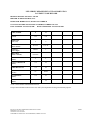


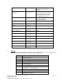


![1127117 - [PROJECT.TOC] - Performance Heating & Plumbing](http://vs1.manualzilla.com/store/data/005895106_1-55e9d6c83dbc31a8ba61d6bb401245cf-150x150.png)