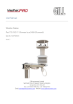
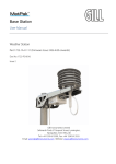
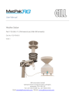
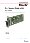
1
MicroTCA Shelf
User’s Manual
Product Number:
10849-005
Doc-No: 63972-184_R1.0
January 25, 2007
Rev.
Date updated
Change
R1.0
January 25, 2007
Initial Release
Impressum:
Schroff GmbH
D-75334 Straubenhardt, Germany
The details in this manual have been carefully compiled and
checked - supported by certified Quality Management System
to EN ISO 9001/2000
The company cannot accept any liability for errors or misprints.
The company reserves the right to amendments of technical
specifications due to further development and improvement of
products.
Copyright
© 2007
All rights and technical modifications reserved.
Schroff MicroTCA Shelf
10849-005
1
2
3
4
Safety ................................................................................................................. 1
1.1
Safety Symbols used in this document................................................................ 1
1.2
General Safety Precautions................................................................................. 1
1.3
References and Architecture Specifications ........................................................ 2
1.4
Product Definition ................................................................................................ 2
1.5
Terms and Acronyms........................................................................................... 2
Hardware Platform............................................................................................ 6
2.1
Front View............................................................................................................ 7
2.2
ESD Wrist Strap Terminal.................................................................................... 7
Backplane 23005-418........................................................................................ 9
3.1
Backplane Topology ............................................................................................ 9
3.2
Fabric Interface.................................................................................................. 10
3.3
3.2.1
Common Options .................................................................................
3.2.2
Fat Pipe ...............................................................................................
3.2.3
Extended Fat Pipe ...............................................................................
Synchronization Clock Interface ........................................................................
3.4
Intelligent Platform Management Bus (IPMB).................................................... 10
3.5
3.4.1
IPMB-L ................................................................................................. 10
3.4.2
IPMB-0 ................................................................................................. 10
JTAG.................................................................................................................. 10
3.6
Carrier FRU SEEPROM .................................................................................... 11
3.7
Carrier Number .................................................................................................. 11
3.8
Cooling Unit Connectors.................................................................................... 11
10
10
10
10
Cooling Unit .................................................................................................... 13
4.1
Air Filter ............................................................................................................. 13
4.2
Introduction ........................................................................................................ 13
4.3
Air Filter Replacement ....................................................................................... 13
4.4
Air Filter Presence Sensor................................................................................. 13
4.5
Cooling Units ..................................................................................................... 14
4.6
Cooling Unit Connectors and Indicators ............................................................ 15
4.7
Cooling Unit IPMB Addresses ........................................................................... 16
4.8
Smart Fan Controller Block Diagram ................................................................. 16
4.9
Telco Alarms...................................................................................................... 17
4.9.1
Telco Alarm Interface...........................................................................
4.9.2
Telco Alarm LEDs ................................................................................
4.9.3
Alarm Silence Push Button ..................................................................
4.9.4
Alarm Reset .........................................................................................
4.9.5
Telco Alarm Connector (DB15-male)...................................................
4.10 Serial Interface...................................................................................................
www.a-tca.com / www.schroff.biz
I
17
17
17
17
18
18
R1.0, January 25, 2007
Schroff MicroTCA Shelf
10849-005
5
Technical Data ................................................................................................ 19
5.1
Part Numbers..................................................................................................... 19
5.2
Shelf Dimensions............................................................................................... 20
www.a-tca.com / www.schroff.biz
II
R1.0, January 25, 2007
Schroff MicroTCA Shelf
Safety
10849-005
1 Safety
The intended audience of this User’s Manual is system integrators and hardware/
software engineers.
1.1 Safety Symbols used in this document
Hazardous voltage!
This is the electrical hazard symbol. It indicates that there are dangerous
voltages inside the Shelf.
Caution!
This is the user caution symbol. It indicates a condition where damage of the
equipment or injury of the service personnel could occur. To reduce the risk of
damage or injury, follow all steps or procedures as instructed.
Danger of electrostatic discharge!
The Shelf contains static sensitive devices. To prevent static damage you must
wear an ESD wrist strap.
1.2 General Safety Precautions
Warning!
Voltages over 60 VDC can be present in this equipment. This equipment is
intended to be accessed, to be installed and maintained by qualified and
trained service personnel only.
•
Service personnel must know the necessary electrical safety, wiring and connection
practices for installing this equipment in a telecommunication
environment.
•
Install this equipment only in compliance with local and national electrical codes.
•
For additional information about this equipment, see the PICMG MicroTCA
Specification (www.picmg.com).
www.a-tca.com / www.schroff.biz
1
R1.0, January 25, 2007
Schroff MicroTCA Shelf
Safety
10849-005
1.3 References and Architecture Specifications
•
PICMG® MicroTCA® Base Specification
(www.picmg.com)
•
PICMG® AMC® Base Specification
(www.picmg.com)
1.4 Product Definition
The Schroff 10849-005 is a 6 U MicroTCA Shelf, 9+2+2 slot for AMC Single Full-size
modules.
1.5 Terms and Acronyms
Table 1: Terms and Acronyms
AMC
Advanced Mezzanine Card. AMC defines a modular card that extends the functionality
of a Carrier board. Often referred to as mezzanines, these cards called also „AMC
Modules.
Backplane
An interconnecting device with connectors, allowing Modules to plug into it
Board
An electronic assembly usually consisting of components mounted on a printed circuit
Card Guide
A mechanical component that provides for the AdvancedMC guidance feature in a Slot
Carrier Local
Address
The combination of Site Type and Site Number that uniquely identify a Module within a
MicroTCA Carrier
Carrier Manager
A logical function that manages and controls the AdvancedMC Modules, OEM Modules, PMs, and CUs in a MicroTCA Carrier through a set of signals controlled by the
PMs together with the IPMB links
Carrier Number
A value to uniquely identify a MicroTCA Carrier within a Shelf
Channel
A group of up to four Ports in the Fat Pipes region which are logically grouped together
via E-Keying to define the physical traces of a Link between Link partners. Multiple
Channels can be aggregated for a wider Link.
Channel ID
An index into the list of AMC Channels that are defined on an MCH or on a Module
CO
Central Office
Common Options
Region
The low order portion of the AdvancedMC Lane mappings, where Lanes are defined as
common control fabric interfaces. MicroTCA uses these as a basic interconnect
between the AdvancedMCs and MCHs.
Contact List
Defines the use of each contact. Directed signals appear in the lists differently, as applicable to the respective viewpoint of the Module and the MicroTCA Backplane.
Cooling Unit (CU)
A subassembly including fans or blowers to move air to cool a MicroTCA Shelf and
related support electronics
CU
See Cooling Unit
Cube
A MicroTCA packaging option where AdvancedMCs, MCHs, PMs, cooling, and
mechanical elements are all packaged in a small, roughly cubic enclosure that is
approximately 200 mm or 8 in. on a side
Double-Width Slot
Mounting location on a MicroTCA Shelf for a Full-Height or Half-Height Double-Width
Module. Double-Width Slots may be created by removing a Strut and Card Guide
between two Single-Width Slots.
Double-Width Mod- A Module that is roughly twice the width of a Single-Width AdvancedMC Module. Douule
ble-Width AdvancedMCs measure approximately 150 mm wide.
EIA
Electronic Industry Association
Electronic Keying
or E-Keying
Abbreviation for Electronic Keying. Electronic Keying defines the process in which a
MicroTCA Shelf determines if the Control and Fabric interfaces on a Module are compatible with the MicroTCA Shelf interconnects and the other Modules they reach.
www.a-tca.com / www.schroff.biz
2
R1.0, January 25, 2007
Schroff MicroTCA Shelf
Safety
10849-005
EMC
Electromagnetic Compatibility is the condition that prevails when telecommunications
(communication-electronic) equipment is collectively performing its individual designed
functions in a common electromagnetic environment without causing or suffering unacceptable degradation due to electromagnetic interference to or from other equipment/
systems in the same environment.
EMC Gasket
An electrically conductive elastic stripe mounted to defined edges of the Face Plate
providing EMC closure around the AdvancedMC Slots
EMMC
Enhanced Module Management Controller, used on Cooling Units, Power Module, and
OEM Modules. See Module Management Controller (MMC).
ESD
Electrostatic Discharge
ETSI
European Telecommunications Standards Institute
Extended Region
The high order portion of the AdvancedMC Lane mappings that are typically used to
carry special or high speed data streams. MicroTCA uses the Extended Region to provide high bandwidth interconnects beyond what can be carried on the Common
Options Region or Fat Pipes region.
Fabric Interface
The set of MCH Fabric Channel interfaces that provides up to seven Fabric Channels
to the AdvancedMCs
Fabric, Fabric
Channel
The connection where the MCH is the endpoint of a Slot-to-Slot connection to one-to
four Ports on an AdvancedMC
Face Plate
The front-most element of a Module, attached perpendicular to the PCB, which serves
to mount Connectors, indicators, controls, and also seals the front of the Subrack for
airflow and EMC
Fat Pipe
A data transmission circuit or network that is capable of carrying large amounts of data
without significantly degrading the speed of transmission. The term is derived from the
simple plumbing fact that a larger diameter pipe will carry more fluid (or gas) at a
greater rate than a smaller one. MicroTCA uses Fat Pipes as high bandwidth interconnects to supplement the Common Options Region.
Frame
An enclosure used for mounting one or more MicroTCA Shelves
FRU
Field Replaceable Unit, any entity that can be replaced by a user in the field
FRU Device ID
A value that uniquely identifies a FRU relative to an IPM Controller. In MicroTCA the
most frequent use of FRU Device ID is to uniquely identify a FRU within a MicroTCA
Carrier relative to the Carrier Manager.
FRU Information
Data that describes a FRU with an emphasis on data that characterizes the FRU. Format for this data is described in IPMI Platform Management FRU Information Storage
Definition and extended herein.
Full-Height Module
Modules that have a Full-Height Face Plate and allow for taller components on Component Side 1 of the Module. Face Plate height is 28.95 mm.
GbE
Gigabit Ethernet (1000BASE-BX)
Gbps
Gigabits (= 1,000,000,000 bits) per second
GBps
Gigabytes (= 1,000,000,000 bytes) per second
Geographic
Address (GA)
Identifies the Site Number part of the Carrier Local Address of a Slot in a MicroTCA
Carrier via three, three-state signals. Each valid GA combination of the three signals
maps to a specific Slot in a MicroTCA Carrier.
HA
High Availability
The component height on Component Side 1 of Half-Height Modules is optimized to
allow for two stacked Modules to equally split the maximum height (AdvancedTCA
Half-Height Module
pitch) available. The term Half-Height should not be taken literally as being half of a
Full-Height Module. Face Plate height is 13.88 mm.
Hot Swap
To remove a component (e.g., an AdvancedMC Module) from a system (e.g., an
MicroTCA Shelf) and plug in a new one while the power is still on and the system is still
operating
Hot Swap Switch
A switch that is integrated with the Module Latch Mechanism so that its state reflects
the state of the Latch. The Hot Swap Switch is disconnected when the Module Handle
is fully inserted.
HP
Horizontal Pitch. A measure of Module-to-Module spacing equaling 0.2 in.
Intelligent FRU
A FRU containing a management controller. Intelligent FRUs include the AdvancedMCs, MCHs, CUs, PMs, and OEM Modules, etc.
www.a-tca.com / www.schroff.biz
3
R1.0, January 25, 2007
Schroff MicroTCA Shelf
Safety
10849-005
IPMB
Intelligent Platform Management Bus. The lowest level hardware management bus as
described in the Intelligent Platform Management Bus Communications Protocol Specification.
IPMB-0
A dual redundant IPMB that connects MCMCs and EMMCs in a MicroTCA Carrier.
Electrically and logically separate from the Local IPMB (IPMB-L).
IPMB-A, IPMB-B
Intelligent Platform Management Buses A and B, respectively. Refers to the two redundant IPMBs that aggregate into IPMB-0.
IPMB-L or Local
IPMB
Connects AdvancedMC’s MMC with the MCH’s MCMC. Electrically and logically separate from the MCMC’s IPMB-0.
IPMI
Intelligent Platform Management Interface. A specification and mechanism for providing inventory management, monitoring, logging, and control for elements of a computer
system as defined in Intelligent Platform Management Interface Specification.
JTAG
Formally, Joint Test Action Group, an organization that proposed adoption of a specification for a test access port and boundary-scan architecture. Informally, but commonly,
the standard, namely IEEE Std 1149.1, that arose from the efforts of the Joint Test
Action Group.
JTAG Switch Mod- A Module that controls the distribution of JTAG signaling to the AdvancedMCs and
ule (JSM)
MCHs within a MicroTCA Carrier
Keying Block
Mechanical entity installed on the backplane used to allow full insertion of Modules that
comply with specific mating requirements related to optional Auxiliary Connectors and
prevent full insertion of Modules that don't comply
Lane
1. A set of differential signal pairs, one pair for transmission and one pair for reception.
One or more Lanes operate together to form a Link 2. E-Keying definition of a differential pair associated with a specific Fabric Link (e.g., a Link generally consists of
Lanes[x:0])
Ground, or GND
The reference potential for logic signaling and local power distribution on the MicroTCA
Shelf and on the Module
MAC
Media Access Control
Managed FRU
Either an Intelligent FRU or a FRU that is represented by an Intelligent FRU via a FRU
Device ID
Management
Power (MP)
The 3.3 V power for a Module's management function, individually provided to each
Slot by the MicroTCA Shelf
Management
Power Channel
An independently managed electrical path that carries Management Power to a Module
from a bulk power source
MCH
See MicroTCA Carrier Hub
MCH Crossover
Channel
An interface between two MCHs used for implementation-defined communication
MCH Update
Channel
An interface between two MCHs used to synchronize state information
MCMC
See MicroTCA Carrier Management Controller
MicroTCA
This specification, governing the application of AdvancedMCs directly on a Backplane.
Although not preferred, it is also acceptable to abbreviate it uTCA or ÏTCA.
MicroTCA Carrier
A group of functions conforming to AMC.0 required to properly support up to twelve
AdvancedMC Modules connected together via a common Backplane. The MicroTCA
Carrier functions include: power regulation and distribution, hardware platform management, fabric connectivity and optionally clock distribution and JTAG test control.
MicroTCA Carrier
Hub (MCH)
An assembly providing MicroTCA Carrier functions needed to support up to twelve
AdvancedMCs including MCMC, optional ShMC, optional Fabric switch, and clock.
MicroTCA Carrier Management controller on the MCH. The required management controller that interManagement Con- faces to AdvancedMC MMCs via IPMB-L and to CU, PM, and OEM Module EMMCs via
IPMB-0.
troller (MCMC)
MMC
The required management controller on an AdvancedMC Module which interfaces to
the MicroTCA Carrier Manager on the MCH via IPMB-L Module Refers to any
MicroTCA Module types, including CU, PM, MCH, OEM Module, or AdvancedMC
Module EMC Gas- Compressible woven EMC material along the left hand side and the bottom of the Modket
ule
Module Handle
Hand grip that is connected to the Module Latch Mechanism, provides user interface
that initiates Hot Swap sequence and Module removal
www.a-tca.com / www.schroff.biz
4
R1.0, January 25, 2007
Schroff MicroTCA Shelf
Safety
10849-005
Module Latch
Mechanism
Mechanism to hold the Module locked in the Slot with the Module in contact with the
bottom of the Slot. The Module Latch Mechanism also provides coupling to the Hot
Swap Switch.
Module LEDs
The collective name for the following LEDs available at the Module Face Plate: BLUE
LED, LED 1, LED 2, LED 3
MP
See Management Power
MTBF
Mean Time Between Failure(s)
NEBS
Network Equipment Building Systems. A specification published by Telecordia governing the environmental characteristics of telecommunications equipment.
Payload
The primary function that a FRU provides. This includes all the hardware on the FRU
except that associated with management. It may also include the firmware, operating
system and application software running on the Payload hardware.
Payload Interface
The interface, usually local to the Module, between an (E)MMC and its Payload
Payload Power
The nominal 12 V supply power, individually provided to each Slot by the MicroTCA
Shelf for the payload function of the Module
Payload Power
Channel
An independently managed electrical path that carries Payload Power to a Module from
a bulk power source
PICMGÆ
PCI Industrial Computer Manufacturers Group (PICMG). An industry standards body
responsible for the creation of specifications such as AdvancedTCA, AdvancedMC,
and MicroTCA.
PM
See Power Module
Port
A set of differential signal pairs, one pair for transmission and one pair for reception
Power Channel
A FRU connection to the Power Subsystem, consisting of Payload Power, Management Power, ENABLE# and PS1#
Power Module
(PM)
Front accessible Module that controls the power entry, conversion and distribution of 12
V Payload Power to the Modules within a MicroTCA Shelf
Power Module
Input Connector
The connector on the PM Face Plate to which input power is connected
Power Module OutThe PM connector that mates with the backplane connector
put Connector
Power Subsystem
The PMs operating together in a MicroTCA Carrier
Primary PM
The PM that provides primary power for a given power channel
PWR
See Payload Power
Redundant PM
A PM that takes over for any failed Primary PM
RoHS
Restriction of the Use of Certain Hazardous Substances
Sensor Data
Record (SDR)
A data structure record that describes the properties of a sensor, management controller or FRU Information device. Defined in IPMI.
Shelf
An electronic assembly consisting of the Subrack, Backplane, Modules, cooling
devices, power subsystems, etc. Also historically known as a chassis. Shelves are usually mounted in Frames.
Shelf-Carrier ManA logical IPMB between the Shelf Manager and the Carrier Managers
ager Interface
Shelf Ground
The electrical potential of the metal Frame of the system, the Face Plate of the
MicroTCA Shelf, and the Face Plate of the Module. It is important for electrical safety.
Shelf Manager
The entity responsible for managing the cooling in a MicroTCA Shelf. It also routes
messages between the System Manager Interface and the Shelf-Carrier Manager
Interface, provides interfaces to system repositories, and responds to event messages.
Single-Width Mod- AdvancedMC Module with a width around 74 mm which fits in a Single-Width
ule
AdvancedMC Slot
Slot
The union of a Connector and a Card Guide that defines the position of one
AdvancedMC, MCH, Power Module, OEM Module or CU. Slots are similar in concept to
the Bays used in the AMC.0 specification. A MicroTCA Subrack typically contains multiple Slots.
Slot Number
Uniquely identifies a Slot within a Shelf
Startup PM
A Power Module selected by the Power Subsystem during power up, to operate in
autonomous mode and automatically provide Management Power, asserts ENABLE#,
and provide Payload Power to CU and conditionally to MCH Power Channels that are
present.
www.a-tca.com / www.schroff.biz
5
R1.0, January 25, 2007
Schroff MicroTCA Shelf
Hardware Platform
10849-005
Subrack
A mechanical assembly that provides the interface to Modules, including AdvancedMCs, and consists of the Card Guides, ESD discharge, alignment/keying, Handle interface, Face Plate mounting hardware, EMC Gasketing, and Backplane interface
System Event Log
(SEL) Persistent Storage for events as defined by IPMI
System Manager
A level of management functionality above the Shelf Manager charged with the management of an entire system, whatever that may mean in a specific implementation
System Manager
Interface The communication interface between Shelf Manager and System Manager
Tier
A horizontal row of Modules across a Shelf
Zone 3
A region used for I/O expansion typically above an AdvancedMC Connector within a
Slot (standard vertical orientation, viewed from the front)
2 Hardware Platform
The Schroff MicroTCA Shelf implements the following features:
•
Compliant to PICMG MicroTCA Base specification
•
Shielded case with 19” rack mounting brackets
•
MicroTCA Backplane with radial IPMI-L from both MCH slots to all AMC slots and
bused IPMB-0 among MCHs, PMs and CUs.
The Backplane provides:
- 9 AMC Single Full-size slots
- 2 redundant MicroTCA Carrier Hub (MCH) slots (Single Full-size)
- 2 Power Module (PM) slots (9 HP Single)
•
Active cooling through two hot-swappable Cooling Units (CUs)
providing each:
- 2 temperature controlled 12 VDC fans.
- Smart Fan Controller
- Telco Alarm Interface (Bottom Cooling Unit)
•
Front accessible air inlet filter
www.a-tca.com / www.schroff.biz
6
R1.0, January 25, 2007
Schroff MicroTCA Shelf
Hardware Platform
10849-005
2.1 Front View
Figure 1: Front View
12807800
1
Top Cooling Unit
5
MicroTCA Backplane
2
Card Cage with Guide Rails
6
Air Filter
3
Cable Tray
7
Bottom Cooling Unit with Telco
Alarms
4
ESD Wrist Strap Terminal
2.2 ESD Wrist Strap Terminal
Danger of electrostatic discharge!
Static electricity can harm delicate components. You must wear an ESD wrist
strap before exchanging any part or electric component!
The ESD Wrist Strap Terminal (4 mm banana jack) is located at the upper front side of
the Shelf.
www.a-tca.com / www.schroff.biz
7
R1.0, January 25, 2007
Schroff MicroTCA Shelf
Hardware Platform
10849-005
www.a-tca.com / www.schroff.biz
8
R1.0, January 25, 2007
Schroff MicroTCA Shelf
Backplane 23005-418
10849-005
3 Backplane 23005-418
The 9+2+2 slot MicroTCA Backplane provides:
•
9 AMC Single Full-size slots (6 HP)
•
2 MicroTCA Carrier Hub (MCH) slots (6 HP)
•
2 Power Module (PM) slots (9 HP)
•
2 Connectors for Cooling Units
3.1 Backplane Topology
Figure 2: Backplane Topology
MCH1 Fabric [A]
to AMC Port 0
MCH2 Fabric [A]
to AMC Port 1
AMC Port 2
AMC Port 3
Fat Pipe
MCH1 Ports [D:G]
to AMC Ports [4:7]
4
4
4
4
4
4
4
4
4
4
4
4
4
4
4
4
4
4
Extend. Fat Pipe
MCH2 Ports [D:G]
to AMC Ports [8:11]
Clocks
MCH1 CLK1
to AMC CLK1
Clocks
MCH2 CLK1
to AMC CLK3
Bi-direct. Clocks
AMC CLK2
to MCH1 CLK2
PM1#
MCH1#
Bi-direct. Clocks
AMC CLK2
to MCH2 CLK2
AMC1#
AMC2#
AMC3#
AMC4#
AMC5#
AMC6#
AMC7#
AMC8#
AMC9#
MCH2#
PM2#
12806805
www.a-tca.com / www.schroff.biz
9
R1.0, January 25, 2007
Schroff MicroTCA Shelf
Backplane 23005-418
10849-005
3.2 Fabric Interface
3.2.1 Common Options
MCH1 Fabric Port A is routed to all AMC slots Port 0 in a radial configuration.
MCH2 Fabric Port A is routed to all AMC slots Port 1 in a radial configuration.
AMC Ports 2 and 3 are direct slot to slot connections to support CPU/HDD
configurations.
3.2.2 Fat Pipe
MCH1 Ports [D:G] are routed to all AMC slots Port [4:7] in a radial configuration.
3.2.3 Extended Fat Pipe
MCH2 Ports [D:G] are routed to all AMC slots Port [8:11] in a radial configuration.
3.3 Synchronization Clock Interface
Reference clocks from each MCH are connected to each AdvancedMC, and a single
clock from each AdvancedMC is routed to each MCH.
Clock 1 from MCH1 is routed to Clock 1 on each AdvancedMC. Clock 1 on MCH2 is
routed to Clock 3 on each AdvancedMC. This allows redundant clocks from the two
MCHs to each AdvancedMC.
Clock 2 is the line recovered clock from the AdvancedMC to both MCHs.
3.4 Intelligent Platform Management Bus (IPMB)
MicroTCA uses an Intelligent Platform Management Bus (IPMB) for management
communications.
3.4.1 IPMB-L
The IPMB among AdvancedMCs and the MCHs is non-redundant and implemented in
a radial topology. This IPMB called Local IPMB (IPMP-L)
3.4.2 IPMB-0
The IPMB among the MCH, the PM and the CU is called IPMB-0. The reliability of the
IPMB-0 is improved by the addition of a second IPMB, with the two IPMBs referenced
as IPMB-A and IPMB-B.
The IPMB-A and IPMB-B are routed in a bused configuration.
IPMB-A and IPMB-B are electrically and logically separate from the Local IPMB
(IPMB-L)
3.5 JTAG
JTAG signals are not supported.
www.a-tca.com / www.schroff.biz
10
R1.0, January 25, 2007
Schroff MicroTCA Shelf
Backplane 23005-418
10849-005
3.6 Carrier FRU SEEPROM
Two SEEPROMS are located at the backside of the Backplane. The SEEPROMS are
connected to both MCHs through I²C-busses.
The I²C-addresses of the SEEPROMs is 0xa4.
3.7 Carrier Number
Each MicroTCA Carrier shall have a unique Carrier Number, ranging from 1 to 16 in its
MicroTCA Shelf. To provide the Carrier Number, a mechanical DIP switch and a
PCF8574A I²C I/O expander is located on the Backplane.
The four-bit DIP switch is connected to the lower four bits of the I/O lines of the
PCF8574A I²C I/O expander. The I/O expander connects to the MCMC’s private I²C bus.
The MCMC reads the DIP switch setting from the I/O expander, adds one, and uses the
result as its Carrier Number.
Two DIP Switches (for redundancy) are located on the Backplane. They are
user-accessible after removing the rear panel.
Table 2: I²C Addresses
s
PCF8574A I/O expander
0x3e
3.8 Cooling Unit Connectors
Two connectors for intelligent Cooling Units are located on the upper and lower side of
the Backplane.
Table 3: Cooling Unit Connector Pin assignment
PIN
A
B
C
1
+12 V
+12 V
+12 V
2
+12 V
+12 V
+12 V
3
+12 V
+12 V
GND
4
GND
GND
GND
5
3.3 V MP
CU_ENABLE
CU_PRESENT
6
IPMB0_SCL_A
IPMB0_SDA_A
IPMB0_SCL_B
7
IPMB0_SDA_B
GA0
GA1
8
GA2
GND
GND
9
GND
GND
GND
12
GND
GND
GND
13
Air Filter Present GND
GND
10
11
GND
14
15
16
www.a-tca.com / www.schroff.biz
11
R1.0, January 25, 2007
Schroff MicroTCA Shelf
Backplane 23005-418
10849-005
www.a-tca.com / www.schroff.biz
12
R1.0, January 25, 2007
Schroff MicroTCA Shelf
Cooling Unit
10849-005
4 Cooling Unit
4.1 Air Filter
Figure 3: Air Filter
12807801
1
Filter Element
3
Filter Tray
2
Handle
4
Spring mounted ball lock
4.2 Introduction
The MicroTCA Shelf provides a front replaceable air filter.
The filter meets the requirements of the Telcordia Technologies Generic Requirements
GR-78-CORE specification.
4.3 Air Filter Replacement
The air filter can be removed by pulling the air filter's handle. To re-install, push the air
filter into the guide rails at each side of the shelf until the spring mounted ball lock
engage.
When installing the air filter, the filter element must be in top position
4.4 Air Filter Presence Sensor
The air filter presence is detected by a reed switch located on the Backplane. The reed
switch is activated by a magnet at the rear side of the air filter metal frame.
The signal of the Air Filter Presence Sensor is hosted by the Cooling Units.
www.a-tca.com / www.schroff.biz
13
R1.0, January 25, 2007
Schroff MicroTCA Shelf
Cooling Unit
10849-005
4.5 Cooling Units
The MicroTCA Shelf provides two front-pluggable Cooling Units.
Each Cooling Unit contains two 12 VDC fans and a Schroff MicroTCA Smart Fan
Controller (SFC). The SFC has a Enhanced Module Management Controller (EMMC)
onboard that communicate with the Carrier Manager over IPMB-0. The SFC controls the
fan speed, provides hot-swap functionality and an optional Telco Alarm Interface.
Two types of Cooling Units are available:
•
20849-180: Cooling Unit with Telco Alarm interface providing 3 Telco Alarm LEDs, a
Telco Alarm connector (DB15 male) and a Telco Alarm Silence push button.
•
20849-208: Cooling Unit without Telco Alarm Interface
Figure 4: Cooling Unit 20849-180
12807802
Table 4: Data Fans
e
Input voltage nominal
12 VDC
Airflow (free blow)
460 m³/h / 270 cfm (Each Fan)
Fan Speed (max)
3750 rpm
Figure 5: Airflow
www.a-tca.com / www.schroff.biz
14
R1.0, January 25, 2007
Schroff MicroTCA Shelf
Cooling Unit
10849-005
4.6 Cooling Unit Connectors and Indicators
The front panel includes the following indicators:
• Green LED – “In-Service”
• Red LED – “Out of Service”
• Blue LED – “Hot-Swap”
The Hot-Swap switch indicates to the Shelf Managers that the Cooling Unit is
about to be removed. Once the operator pushes the Hot-Swap switch, the Shelf
Manager is informed of the pending extraction. When the Shelf Manager feels it
is “safe“ to remove the Fan Tray, the blue Hot-Swap LED illuminates solid.
Table 5: LEDs on Fan Tray front panel
Color
Green
Description
Status
In-Service LED
Off
Condition
No Power to the Fan Tray
Solid green
Normal Operation
Red
Alarm LED
Solid red
Attention Status (error condition)
Blue
Hot Swap LED
Off
In use
Long blink
Searching for Shelf Manager
Short blink
Preparing for extraction
Solid blue
Ready to remove
Figure 6: Fan Controller Backplane Connector
12807804
Table 6: Cooling Unit Connector Pin assignment
PIN
A
B
C
1
+12 V
+12 V
+12 V
2
+12 V
+12 V
+12 V
3
+12 V
+12 V
GND
4
GND
GND
GND
5
3.3 V MP
CU_ENABLE
CU_PRESENT
6
IPMB0_SCL_A
IPMB0_SDA_A
IPMB0_SCL_B
7
IPMB0_SDA_B
GA0
GA1
8
GA2
GND
GND
9
GND
GND
GND
10
11
GND
12
GND
GND
GND
13
Air Filter Present GND
GND
14
15
16
www.a-tca.com / www.schroff.biz
15
R1.0, January 25, 2007
Schroff MicroTCA Shelf
Cooling Unit
10849-005
4.7 Cooling Unit IPMB Addresses
Table 7: Cooling Unit IPMB Addresses
Upper Cooling Unit
0xAA
Lower Cooling Unit
0xA8
4.8 Smart Fan Controller Block Diagram
Figure 7: Smart Fan Controller Block Diagram
Hot Swap LED
FRU SEEPROM (0xA0/50)
LED
Buffer
GND
LM75 Temp. (0x96/4B)
Alarm LED
I2C Buffer
OK LED
I2C Buffer
SDA/SCL (IPM Bus A)
SDA/SCL (IPM Bus B)
Ga0
Ga1
Ga2
Hot Swap Switch
MON_12V
ALARM SILENCE
MON_12V
ALARM LEDs
12 V
Critical
LED
Buffer
12 V
Major
3.3 V
PWM
Minor
Tacho
3.3 V MP
PWM
C-Voltage
Critical Alarm
TELCO Alarm Connector
+12 V
Hot Swap
Controller
EMMC-CU
Backplane Connector
Enable
PRESENT
12 V
Major Alarm
Minor Alarm
Power Alarm
Minor Clear
PWM
Tacho
TxD
RxD
Major Clear
PWM
C-Voltage
RS232 Interface
TxD
RxD
X851
1 2
3 4
5 6
7 8
9 10
12807803
www.a-tca.com / www.schroff.biz
16
R1.0, January 25, 2007
Schroff MicroTCA Shelf
Cooling Unit
10849-005
4.9 Telco Alarms
4.9.1 Telco Alarm Interface
The Cooling Unit provides a Telco Alarm interface on the DB15-male connector.
Three relay outputs are used for remote alarm distribution, reflecting the state of
the three Alarm LEDs. The relays are capable of carrying 72 VDC or 1 A with a
max. rating of 30 VA.
4.9.2 Telco Alarm LEDs
These LEDs indicate presence of Critical, Major and Minor alarms as follows:
Table 8: Telco Alarm LEDs
State
Description
Off
No alarm active
On
Alarm active
Flashing
Alarm active, but silenced
4.9.3 Alarm Silence Push Button
The Alarm Silence push button on the Cooling Unit faceplate deactivates the
alarm relays. During the time Alarm Silence is activated, the Alarm LEDs flash.
By pressing the Alarm Silence push button a second time, the alarm relays are
reactivated and the Alarm LEDs are solid.
The Alarm Silence push button only activates the Alarm Silence state, but
does not reset the alarms. If the silence interval (default 600 s) is exceeded
without resolving the alarms, the alarms will be re-initiated.
4.9.4 Alarm Reset
Hardware Reset:
Two relay inputs at the DB15 connector are used to reset the Minor and Major
alarm state.
The reset inputs accept timed pulse inputs for clearing Minor and Major alarm
states. Reset is accomplished by asserting a voltage differential from 3.3 VDC
to 72 VDC for between 200 ms and 300 ms. The acceptance voltage range is
from 0 to 48 VDC continuous (handles up to 60 VDC at a 50% duty cycle). The
current drawn by a reset input does not exceed 12 mA.
There is no hardware reset (reset input) for the Critical Alarm state.
Software Reset:
The RMCP and CLI functions can be used to set and reset the Telco Alarms
(incl. Critical Alarm). See the Shelf Manager External Interface Reference for
more information.
www.a-tca.com / www.schroff.biz
17
R1.0, January 25, 2007
Schroff MicroTCA Shelf
Cooling Unit
10849-005
4.9.5 Telco Alarm Connector (DB15-male)
Figure 8: Telco Alarm Connector (DB15-male)
12705896
Table 9: Telco Alarm Connector Pin Assignment
Pin
Name
Description
Pin
Name
Description
1
AMIR+
Minor Reset+
9
AMINC
Minor Alarm – NC
2
AMIR-
Minor Reset-
10
AMINCOM
Minor Alarm – COM
3
AMAR+
Major Reset+
11
AMANO
Major Alarm – NO
4
AMAR-
Major Reset-
12
AMANC
Major Alarm – NC
5
ACNO
Critical Alarm - NO
13
AMACOM
Major Alarm – COM
6
ACNC
Critical Alarm - NC
14
APRCO
Pwr Alarm – NO
7
ACCOM
Critical Alarm - COM
15
APRCOM
Pwr Alarm - COM
8
AMINO
Minor Alarm – NO
Shield
Shelf-GND
Shelf Ground
4.10 Serial Interface
A Serial Interface for debugging and firmware update is implemented on the Smart Fan
Controller.
Figure 9: Serial Interface Connector (C851)
12807807
Table 10: Serial Interface Connector Pin Assignment
Pin
Signal
1
TxD
3
RxD
2,4,6,8,10
GND
www.a-tca.com / www.schroff.biz
18
R1.0, January 25, 2007
Schroff MicroTCA Shelf
Technical Data
10849-005
5 Technical Data
Table 11: Technical Data
Physical Dimensions
Height
263.90 mm
Width (with mounting brackets)
482.60 mm
Depth
197 mm
Depth (with front cable tray)
257mm
Weight
Weight completely assembled
15 Kg
Environmental
Ambient temperature
+5°C…+45°C
Humidity
+5%...+85%, no condensation
EMI
Conducted Emissions
EN 55022 Class B
Radiated Emissions
EN 55022 Class B
5.1 Part Numbers
Table 12: Part Numbers
Number
Part
10849-005
MicroTCA Shelf for single modules including one Cooling Unit
with Telco Alarms and one Cooling Unit without Telco Alarms
20849-180
Cooling Unit with Telco Alarms
20849-208
Cooling Unit without Telco Alarms
23098-561
12 V Power Feedthrough Module
www.a-tca.com / www.schroff.biz
19
R1.0, January 25, 2007
Schroff MicroTCA Shelf
Technical Data
10849-005
5.2 Shelf Dimensions
Figure 10: Shelf Dimensions
12807808
www.a-tca.com / www.schroff.biz
20
R1.0, January 25, 2007
SCHROFF GMBH
Langenalberstr. 96-100
D-75334 Straubenhardt
www.schroff.biz
www.a-tca.com
Tel.: + 49 (0) 7082 794-0
Fax: +49 (0) 7082 794-200