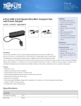
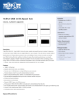
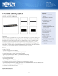
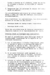
1
SIMADYN D
Digital Control System
User Manual
Subrack SR12.x
Edition 04.97
DK No. 213844
User Manual, Subrack SR12.x
Edition
Status
1
Subrack SR12.x
05.95
2
Subrack SR12.x
04.97
Copying of this document and giving it to others and the use or
communication of the contents thereof is forbidden without express
authority. Offenders are liable to the payment of damages. All rights
are reserved in the event of the grant of a patent or the registration of
a utility model or design.
We have checked the contents of this Manual to ensure that they
coincide with the described hardware and software. However,
deviations cannot be completely ruled-out, so we cannot guarantee
complete conformance. However, the information in this document is
regularly checked and the necessary corrections included in
subsequent editions. We are thankful for any recommendations or
suggestions.
Contents
Contents
Warning information................................ ................................ ................................ ........................ 1
1. Ordering information and supplementary components................................ ................................ . 3
2. Function description................................ ................................ ................................ .................... 3
2.1. Overview ................................ ................................ ................................ ..................... 3
2.2. Bus system................................ ................................ ................................ .................. 4
2.3. Bus arbitration................................ ................................ ................................ .............. 4
2.4. Bus termination................................ ................................ ................................ ............ 4
3. Power supply................................ ................................ ................................ ............................... 5
3.1. Front panel ................................ ................................ ................................ .................. 5
3.2. Input voltage................................ ................................ ................................ ................ 5
3.2.1. 24 V DC voltage for SR12.1 and SR12.2................................ ....................... 5
3.2.2. 115/ 230 V AC for SR12.3 and SR12.4................................ .......................... 6
3.3. Fan assembly in the SR12.1 and SR12.3 subracks................................ ...................... 6
3.4. Battery ................................ ................................ ................................ ......................... 6
3.5. Line filter................................ ................................ ................................ ...................... 7
3.6. Ground connections within the subrack................................ ................................ ........ 7
3.6.1. Subracks SR12.1 and SR12.2 (SP22, SP23)................................ ................. 7
3.6.2. Subracks SR12.3 and SR12.4 (SP22.5, SP23.5)................................ ........... 8
4. Installation guidelines................................ ................................ ................................ .................. 8
4.1. Noise immunity ................................ ................................ ................................ ............ 8
5. Technical data................................ ................................ ................................ ............................. 9
5.1. General data................................ ................................ ................................ ................ 9
5.2. Electrical data SR12.1 (SP22) and SR12.2 (SP23)................................ ...................... 10
5.3. Electrical data, SR12.3 (SP22.5) and SR12.4 (SP23.5)................................ ................ 10
6. STRUC L mask in the master program................................ ................................ ........................ 11
7. Connector assignment................................ ................................ ................................ ................. 12
7.1. Signal assignment, backplane bus................................ ................................ ............... 12
8. Others................................ ................................ ................................ ................................ ......... 12
8.1. Attachments................................ ................................ ................................ ................. 12
8.2. Terminology/ abbreviations................................ ................................ .......................... 12
9. ESD instructions................................ ................................ ................................ .......................... 13
Siemens AG Dk No. 213844
SIMADYN D Hardware User Manual
Edition 04.97
Warning information
Edition 04.97
Siemens AG Dk No. 213844
SIMADYN D Hardware User Manual
Warning information
N O T E!
The information in this Manual does not purport to cover all details or variations in equipment, nor to provide
for every possible contingency to be met in connection with installation, operation or maintenance.
Should further information be desired or should particular problems arise which are not covered sufficiently for
the purchaser’s purposes, please contact your local Siemens office.
Further, the contents of this Manual shall not become a part of or modify any prior or existing agreement,
committment or relationship. The sales contract contains the entire obligation of Siemens. The warranty
contained in the contract between the parties is the sole warranty of Siemens. Any statements contained
herein do not create new warranties nor modify the existing warranty.
Warning information
WARNING!
Electrical equipment has components which are at dangerous voltage levels.
If these instructions are not strictly adhered to, this can result in severe bodily
injury and material damage.
Only appropriately qualified personnel may work on this equipment or in its
vicinity.
This personnel must be completely knowledgeable about all the warnings and
service measures according to this User Manual.
The successful and safe operation of this equipment is dependent on proper
handling, installation, operation and maintenance.
Siemens AG Dk No. 213844
SIMADYN D Hardware User Manual
Edition 04.97
1
Warning information
Definitions
*
QUALIFIED PERSONNEL
*
DANGER
*
WARNING
*
CAUTION
*
NOTE
For the purpose of this User Manual and product labels, a „Qualified person“ is someone who is familiar with the
installation, mounting, start-up and operation of the equipment and the hazards involved. He or she must have
the following qualifications:
1. Trained and authorized to energize, de-energize, clear, ground and tag circuits and equipment in accordance
with established safety procedures.
2. Trained in the proper care and use of protective equipment in accordance with established safety
procedures.
3. Trained in rendering first aid.
For the purpose of this User Manual and product labels, „Danger“ indicates death, severe personal injury and/or
substantial property damage will result if proper precautions are not taken.
For the purpose of this User Manual and product labels, „Warning“ indicates death, severe personal injury or
property damage can result if proper precautions are not taken.
For the purpose of this User Manual and product labels, „Caution“ indicates that minor personal injury or
material damage can result if proper precautions are not taken.
For the purpose of this User Manual, „Note“ indicates information about the product or the respective part of the
User Manual which is essential to highlight.
CAUTION!
This board contains components which can be destroyed by electrostatic
discharge. Prior to touching any electronics board, your body must be electrically
discharged. This can be simply done by touching a conductive, grounded object
immediately beforehand (e.g. bare metal cabinet components, socket protective
conductor contact).
WARNING!
Hazardous voltages are present in this electrical equipment during operation.
Non-observance of the safety instructions can result in severe personal injury or
property damage.
It is especially important that the warning information in all of the relevant
Operating Instructions are strictly observed.
2
Edition 04.97
Siemens AG Dk No. 213844
SIMADYN D Hardware User Manual
Ordering information and supplementary components
1. Ordering information and supplementary components
SR12.1
SR12.2
Supply voltage
Cooling
SP22
24 V DC
Integrated fan
Order No.
6DD1682-0CC0
6DD1683-0CC0
SP23
24 V DC
Self-convection
6DD1682-0CD0
6DD1683-0CD0
Integrated fan
6DD1682-0BC3
6DD1683-0CC5
Self-convection
6DD1682-0BC4
6DD1683-0CD5
with SP22
with SP23
SR12.3 with SP22.5
SP22.5 115/230 V AC
SR12.4
with SP23.5
SP23.5 115/230 V AC
The SR12.x subrack is available in 4 versions. They differ by the power supply. The power supply is
supplied in the subrack and is not separately ordered. However, it can be individually ordered as
spare part.
6DD 1683 - 0AC0
6EW 1000 - 7AA
Lithium battery, pack of 5
Lithium battery, pack of 1
6DD 1682 - 0AJ1
6DD 1682 - 0AJ2
6DD 1682 - 0AJ3
SR81 slot cover
SR82 slot cover
SR83 slot cover
2. Function description
2.1. Overview
The SR12.x subrack is used for mounting SIMADYN D PC boards and the associated SPx. power
supply. The ES902 packaging system for a 233.4 ∗ 220 mm board format according to IEC 297 is
used.
The subrack has 12 slots, each separated by 1 1/3 SPS and a multi-layer mother board as backplane
wiring. All of the slots are clearly labelled.
The SP8, SP9, SP8.5, and SP9.5 power supplies are used as system power supply. They are part of
the SR12.x subrack and are inserted in the upper subrack section. The SP22 (in the SR12.1) and
SP22.5 (in the SR12.3) power supplies have a fan assembly to force-ventilate the SIMADYN D
boards.
A battery insert is part of the power supply which is used to buffer the power supply when the voltage
fails so that no data is lost.
Siemens AG Dk No. 213844
SIMADYN D Hardware User Manual
Edition 04.97
3
Function description
2.2. Bus system
A local bus (L bus) and a continuous communications bus (C bus) for all of the subrack slots is
established through the backplane board. These buses have a 20-bit address/16-bit data bus, control
signals and the power supply for the SIMADYN D boards.
The power supply is connected to the backplane when the power supply is inserted, through a highcurrent connector (X227) with additional control lines.
The system ground for the backplane is connected to the subrack via two H07V-K 2.5 mm (X225,
X226) cables.
2.3. Bus arbitration
A bus cycle is divided into two phases. During the request phase, each processor module which
needs to transmit data via the bus, generates a request via the common open-collector line. The
distribution phase is started when at least one request has been made.
Bus allocation is implemented according to the principle of daisy chain priority, i.e., in the sequence
of the slot numbers. Bus priority is immediately switched to the next processor module when bus
access has been completed or the bus request has not been made by the current bus master. The
distribution cycle is completed when the request from the processor with the highest slot number has
been processed.
New requests can only be made when the common open-collector line has become inactive.
This arbitration technique ensures that each processor module is processed once within a distribution
cycle. The maximum wait time for a processor with the highest slot number can be up to 14 bus
accesses. (P8 missed the request phase, P1-7 becomes active and immediately requests the next
cycle). A bus access is generally approximately 1 µs (without continuous request or LOCK).
The complete arbitration will only function if the daisy chain line is correctly looped from the first to
the last processor of a bus section. Two connector pins (slot 24 has no pins), are located for this
purpose on the righthand side of the bus board next to the 96-pin socket connector. They must always
be jumpered when a SIMADYN D processor board is not inserted in the corresponding socket
connector (jumper on the system board or active bus node). The jumper plugs must be removed
when a SIMADYN D processor board is inserted in the corresponding socket connector.
The subrack is supplied with a complete set of jumper plugs.
2.4. Bus termination
The bus lines at the L- and C buses must be correctly terminated in order to achieve defined voltage
levels on the bus lines when the bus is accessed at the buffer memory or periphery. The bus
terminating resistors are provided on the backplane board of the subrack.
4
Edition 04.97
Siemens AG Dk No. 213844
SIMADYN D Hardware User Manual
Power supply
3. Power supply
3.1. Front panel
The power supplies belong to the subrack. They are inserted into the upper section of the subrack and
screwed into place. The power supplies are supplied, installed in the subracks.
All of the connecting terminals required for the subrack are accessible at the front panel.
SP22 and SP23
SR12.1 and SR12.2
24V DC input voltage
SP22.5 and SP23.5
SR12.3 and SR12.4
115/230V AC input voltage
Input voltage can be changed-over
X1 pin 1
X1 pin 2
X1 pin 3
+24 V
GND
PE
L1
N
PE
X2 pins 1 - 4
X3 pins 1 - 2
X4 pins 1 - 2
Monitors the power supply and fan assembly
Back-up battery supply
Subrack reset
The subrack can be reset by jumpering pins 1 and 2 and X4.
There is also a RESET button which allows the switch-on/off routines to be activated. It is recessed to
prevent accidental actuation.
The 5V, +15V, -15V power supply voltages and ground are accessible at 4 test points. They have
series resistors for short-circuit protection.
Two LEDs indicate correct operation (green LED) and faulted operation (red LED) of the power
supply.
3.2. Input voltage
3.2.1. 24 V DC voltage for SR12.1 and SR12.2
The 24 V input voltage is connected at connector X1. The protective conductor must be connected at
terminal 3. It is not sufficient to just connect a protective conductor to the subrack.
A series fuse should be provided with the following data.
In
=
I∗I∗t =
Is
=
16 A max
6 A2s
32 A (inrush)
The subrack is powered-up when the input voltage is connected. To prevent faults at power-on, all
interface modules must be supplied with power at least 300 ms prior to the system boards. This is
guaranteed by simultaneously connecting the power supply voltage for the subrack and interface
modules.
Siemens AG Dk No. 213844
SIMADYN D Hardware User Manual
Edition 04.97
5
Power supply
3.2.2. 115/ 230 V AC for SR12.3 and SR12.4
The 115/230 V input voltage is connected at connector X1. The protective conductor must be
connected at terminal 3. It is not sufficient to just connect a protective conductor to the subrack. A
switch is provided on the front panel, which can be used to select the supply voltage - either 115 V or
230 V supply voltage. This is factory set at 230 V.
The series fuse should be dimensioned for the following operating data.
In
=
I∗I∗t =
Is
=
1.2A max
0.6 A2s
6 A (inrush)
The subrack is powered-up when the input is connected. To prevent faults at switch-on, all interface
modules must be supplied with power at least 300 ms prior to the system boards. This is guaranteed
by simultaneously connecting the power supply voltage for the subrack and interface modules.
3.3. Fan assembly in the SR12.1 and SR12.3 subracks
The power supplies have a fan assembly with a single fan. The speed of the fan is monitored. The
pulses supplied from the fan are evaluated by the power supply. When a fault condition occurs, a
signal is output via the front panel through a relay contact (24 V, 100mA) at connector X2, pin 3 and
pin 4.
Contact closed:
Contact open:
Fault-free operation
Faulted
It is not permissible that the subrack is used when a fault condition exists - safe operation of the
boards is no longer ensured due to the danger of overtemperature. At power-up, the monitoring
function is delayed so that the subrack can reliably run-up.
The power supply must be removed to replace the fan. The bottom plate assembly is completely
changed with the fan. At 50° C ambient temperature, it is recommended that the fans are changed
after 40,000 operating hours.
The subrack does not have an air filter. If a filter is required, this must be provided at the cabinet.
3.4. Battery
The 3.6 V lithium battery is inserted in the compartment provided and is used to maintain the power
supply for the RAM memory of the SIMADYN D boards.
The battery is monitored by the power supply. If the voltage falls below 3.2 V, the fault is displayed
with a flashing „b“on the 7-segment display of processor module „1“.
The battery can be changed „online“. A battery fault can be acknowledged after it has been rectified.
The battery should be changed every year.
6
Edition 04.97
Siemens AG Dk No. 213844
SIMADYN D Hardware User Manual
Power supply
3.5. Line filter
The power supply has a line filter, which limits radio interference voltages to limit value class A
according to VDE 0871.
3.6. Ground connections within the subrack
3.6.1. Subracks SR12.1 and SR12.2 (SP22, SP23)
Bus board
Ground
Permanent
connection
24 V electrical isolation
Power supply
Siemens AG Dk No. 213844
SIMADYN D Hardware User Manual
SIMADYN D subrack
Edition 04.97
7
Installation guidelines
3.6.2. Subracks SR12.3 and SR12.4 (SP22.5, SP23.5)
Bus board
Ground
Permanent
connection
L1
1
2
N
3
PE
Power supply
SIMADYN D subrack
230 V~
4. Installation guidelines
4.1. Noise immunity
All SIMADYN D housings must be connected to the cabinet ground through the shortest possible
cable - at least 6mm2 cross-section. Potential equalization via the „PE“ power supply connection is
not adequate.
Shielded cables should be connected with the shield on the grounding- or shield rails, and routed to
the terminal module, shielded.
All of the cabinets networked for SIMADYN D drives should be connected using a potential
equalization cable, with at least 16 mm2 cross-section.
Empty slots must be provided with SIMADYN D slot covers (SR81, SR82,SR83).
All boards must be tightly screwed to the subrack.
It is not permissible to use undamped contactors together with SIMADYN D in a cabinet.
If undamped contactors (i.e. no RC elements) are used in cabinets next to SIMADYN D, a panel must
be mounted between the cabinets.
The protective conductor is connected at the subrack and power supply.
8
Edition 04.97
Siemens AG Dk No. 213844
SIMADYN D Hardware User Manual
Technical data
5. Technical data
5.1. General data
INSULATION GROUP
A acc. to VDE 011 PARA. 13, GROUP 2
at 24V DC, 15V, 5V DC
0 to 55 DEGREES C. WITH FORCED VENTILATION
-40 to +70 DEGREES C.
F acc. to DIN 40050
S acc. to DIN 40040
MOUNTED IN STATIONARY EQUIPMENT WHICH IS NOT
NECESSARILY VIBRATION-FREE
ES 902 C
10.5 kg
AMBIENT TEMPERATURE
STORAGE TEMPERATURE
HUMIDITY RATING
ALTITUDE RATING
MECHANICAL STRESSING
PACKAGING SYSTEM
WEIGHT
Output voltage/current
Base load, min.:
Va1: +5.1V ± 0.1V
Ia1: 0 to 26 A
(5% of Ia1)
Base load, min.:
Va2: +15V ± 0.300V
Ia2: 0 to 3.3 A
(5% of Ia2)
Base load, min.:
Va3: -15V ± 0.300V
Ia3: 0 to 3.0 A
(5% of Ia3)
Residual ripple
(measurement bandwidth, 30 MHz)
(above 10% of the base load)< 50 mVpp Va1 (probe 1:1)
< 150 mVpp Va2,Va3
Commutating spikes
(% of VaN)
Current limiting
± 5%
Ia1max = approx. 1.2 x Ia1
Ia2max = approx. 1.2 x Ia2
Ia3max = approx. 1.2 x Ia3
Shock/vibration stressing
Stationary application:
Transport:
acc. to SN29010
severity 12
severity 22
Degree of protection:
IP00
VDE 0110
pollution level 2
VDE 0110
air- and creepage distances
Radio interference suppression VDE0871, limit value class "A"
Siemens AG Dk No. 213844
SIMADYN D Hardware User Manual
Edition 04.97
9
Technical data
5.2. Electrical data SR12.1 (SP22) and SR12.2 (SP23)
1. Input voltages:
DC power supply according to SN 26555, Part 8, DIN IEC 38, Draft
Ve: 24V
Static upper limit
Ve ∗ 1.25 (=30V)
Static lower limit:
Ve ∗ 0.833 (=20V)
Max. input voltage ripple
5%
Non-periodic overvoltages acc. to DIN VDE160, A5.3.1.1.2
V max.:
+35V
Duration:
500 ms
Recovery, min.:
50 s
Brief voltage dips acc. to DIN VDE 0160, A5.3.1.1.3
V min.:
+14.25
Duration:
5 ms
Recovery time, min.:
10 s
Vcc: Va1 - voltage drop across the switching element
2 Overvoltage protection for Va1
via suppressor diode
3 Input voltage protection
fuse
4 Safety regulations
(standard, VDE 0160 December 1990; IEC)
5 Rated insulation voltage:
500 V AC
Test voltage:
Protective separation:
acc. to VDE 0160
The higher-level power supply has the function of
ensuring „protective separation“of the 24 V power
supply for the subrack.
5.3. Electrical data, SR12.3 (SP22.5) and SR12.4 (SP23.5)
1. Input voltages: for Ve = 230V
DC power supply according to SN 26555, Part 8, DIN IEC 3, Draft
Static upper limit
Static lower limit:
Frequency:
Ve ∗ 1,1 (=253V)
Ve ∗ 0.85 (=195.5V)
50/60 Hz +-2.5 Hz
Non-periodic overvoltages according to DIN VDE160, A5.3.1.1.2
V ref. peak value:
Ve ∗ 1.3 (460V)
Duration:
0.3 ms
Recovery time, min.:
0.1 s
Events per hour:
10 max.
Brief voltage dips acc. to DIN VDE 0160, A5.3.1.1.3
V
0
Duration:
5 ms
Recovery time, min.:
0.1 s
Events per hour:
10 max.
Vcc: Va1 - voltage drop across the switching element
10
Edition 04.97
Siemens AG Dk No. 213844
SIMADYN D Hardware User Manual
STRUC L mask in the master program
2 Overvoltage protection of Va1
via suppressor diode
3 Input voltage protection
fuse
4 Safety regulations
(standard, VDE 0160 December 1990; IEC)
5 Rated insulation voltage:
3750 V AC
Test voltage:
Protective separation:
acc. to VDE 0160
Safety extra-low voltage according to
VDE 0805 / EN 60950 with protective separation
6. STRUC L mask in the master program
All 4 subracks have, in version 4.2, the same STRUC L mask. Subrack „SR12“should be called-up.
: SR12
L01 6S = `.
L07 6S = `.
L13 6S = `.
L19 6S = `.
S01 8N = ?
S02 8N = 0
S03 8N = 0
S04 8N = 0
S05 8N = 0
S06 8N = 0
S07 8N = 0
S08 8N = 0
S09 8N = 0
S10 8N = 0
S11 8N = 0
S12.8N = 0
.
.
.
.
.
.
.
.
Siemens AG Dk No. 213844
SIMADYN D Hardware User Manual
"Subrack, 12 slots, L+C bus"
.
.
.
."Lettering"
.
.
.
."strip
"
.
.
.
."Lettering"
.
.
.
."strip
"
"Slot 1: Board (,sub-assembly)"
Edition 04.97
11
Connector assignment
7. Connector assignment
7.1. Signal assignment, backplane bus
X101 to X112 96-pin socket connector DIN 41612, type of construction C (C bus)
X201 to X212 96-pin socket connector DIN 41612, type of construction C (L bus)
Pin No.
Row a
Row b
Row c
1
2
3
4
5
6
7
8
9
10
11
12
13
14
15
16
17
18
19
20
21
22
23
24
25
26
27
28
29
30
31
32
5V
AUX2
AUX1
+15V
AUX0
*LOCK
5VEXT
Vcc
*BATAL
*DSAD
*DSAVE
AB19
*OUTDS
*RESET
*BHE
*BRQ
*BGIN
*BGOUT
*BCLR
*IR0
*IR1
*IR2
*IR3
*RDYIN
*RDY
*WR
*RD
CLK
*CLK.M
*DEN
*HWE
DT/*R
5V
AB20
AB21
+15V
-15V
*CSPER
5VEXT
AB12
0V
AB13
PLC0
AB14
PLC1
AB15
PLC2
AB16
PLC3
AB17
PLC4
AB18
0V
DB11
OV
DB12
PRIVAT
DB13
0V
DB14
0V
DB15
RES
OV
5V
AB22
AB23
+15V
-15V
*CSINI
*RSERQ
AB0
AB1
AB2
AB3
AB4
AB5
AB6
AB7
AB8
AB9
AB10
AB11
DB0
DB1
DB2
DB3
DB4
DB5
DB6
DB7
DB8
DB9
DB10
SBR
SBT
8. Others
8.1. Attachments
Dimension drawing
Drawing, bus board
3SE.465 682 9012.00 MB
1SE.465 682 0012.00
8.2. Terminology/ abbreviations
SV power supply
BGT subrack
12
Edition 04.97
Siemens AG Dk No. 213844
SIMADYN D Hardware User Manual
ESD instructions
9. ESD instructions
Components which can be destroyed by electrostatic discharge (ESD).
Generally, electronic boards should only be touched when absolutely necessary.
The human body must be electrically discharged before touching an electronics board. This can be
simply done by touching a conductive, grounded object directly beforehand (e.g. bare metal cubicle
components, socket outlet protective conductor contact).
Boards must not come into contact with highly-insulating materials - e.g. plastic foils, insulated
desktops, articles of clothing manufactured from man-made fibers.
Boards must only be placed on conductive surfaces.
When soldering, the soldering iron tip must be grounded.
Boards and components should only be stored and transported in conductive packaging (e.g.
metalized plastic boxes, metal containers).
If the packing material is not conductive, the boards must be wrapped with a conductive packing
material, e.g. conductive foam rubber or household aluminum foil.
The necessary ESD protective measures are clearly shown in the following diagram.
a = Conductive floor surface
b = ESD table
c = ESD shoes
Seated
Siemens AG Dk No. 213844
SIMADYN D Hardware User Manual
d = ESD overall
e = ESD chain
f = Cabinet ground connection
Standing
Edition 04.97
Standing / sitting
13
ESD instructions
Drives and Standard Products
Motors and Drive Systems Group
Postfach 3269, D-91050 Erlangen
14
System-Based
Drive
Technology
Edition 04.97
Siemens AG Dk No. 213844
SIMADYN D Hardware User Manual
ESD instructions
Siemens AG Dk No. 213844
SIMADYN D Hardware User Manual
Edition 04.97
15