1
NAPPCI/win & NAPPCI/wnt
User Manual for PCI-1202
Warranty
All products manufactured by ICP DAS are warranted against defective materials
for a period of one year from the date of delivery to the original purchaser.
Warning
ICP DAS assumes no liability for damage consequent to the use of this product.
ICP DAS reserves the right to change this manual at any time without notice. The
information furnished by ICP DAS is believed to be accurate and reliable. However, no
responsibility is assumed by ICP DAS for its use, nor for any infringements of patents
or other rights of third parties resulting from its use.
Copyright
Copyright 1998 by ICP DAS. All rights are reserved.
Trademark
The names used for identification only maybe registered trademarks of their
respective companies.
License
The user can use, modify and backup this software
on a single
machine. The user may not reproduce, transfer or distribute this software, or any
copy, in whole or in part.
NAPPCI/win & NAPPCI/wnt User Manual (Version 2.0) ---- 1
Table of Contents
1. INTRODUCTION................................................................................................................................3
1.1 SOFTWARE INSTALLATION ...............................................................................................................4
1.2 REGISTRATION FOR WINDOWS NT .......................................... ERROR! BOOKMARK NOT DEFINED.
1.3 PLUG&PLAY INSTALLATION FOR WINDOWS NT ..................... ERROR! BOOKMARK NOT DEFINED.
1.4 PLUG&PLAY INSTALLATION FOR WINDOWS 95................................................................................6
1.5 C CALL NAPPCI ...........................................................................................................................11
1.6 MFC CALL NAPPCI......................................................................................................................11
1.7 BC++ CALL NAPPCI ....................................................................................................................12
1.8 VB CALL NAPPCI ........................................................................................................................13
1.9 DELPHI CALL NAPPCI ..................................................................................................................14
1.10 LABVIEW CALL NAPPCI...........................................................................................................15
1.11 DEMO PROGRAM..........................................................................................................................17
2. DLLS FOR WINDOWS 95/NT.........................................................................................................22
2.1 THE CONFIGURATION CODE TABLE ...............................................................................................24
2.2 P1802.H ........................................................................................................................................25
2.3 THE TESTING FUNCTIONS ..............................................................................................................28
2.4 THE M_FUNCTIONS .......................................................................................................................30
2.5 THE DIO FUNCTIONS .....................................................................................................................33
2.6 THE DA FUNCTIONS ......................................................................................................................34
2.7 THE AD FIXED-MODE FUNCTIONS .................................................................................................35
2.8 THE MAGICSCAN FUNCTIONS ........................................................................................................38
2.9 THE PULG&PLAY FUNCTIONS ........................................................................................................44
2.10 THE CONTINUOUS CAPTURE FUNCTIONS .....................................................................................47
2.11 THE OTHER FUNCTIONS ...............................................................................................................51
3. DEMO PROGRAM ...........................................................................................................................52
NAPPCI/win & NAPPCI/wnt User Manual (Version 2.0) ---- 2
1.
Introduction
The NAPPCI/win is a collection of DLLs for Windows 95 application and the
NAPPCI/wnt is for Windows NT 3.51/4.0. These DLLs are 32 bits and can be
called by Visual C/C++, BC++, Visual BASIC, Delphi, and LabVIEW.
The NAPPCI/win consists of these DLLs and device driver that supports the
following product:
•
•
•
•
•
•
P1202.dll, nappci.vxd
→
for PCI-1800/PCI-1802 card
p1602.dll, nappci.vxd
→
for PCI-1602 card
p1202.dll, nappci.vxd
→
for PCI-1202 card
p1002.dll, nappci.vxd
→
for PCI-1002 card
p16r16.dll, nappci.vxd
→
for PCI-P16R16, PCI-P8R8 card
pcid144.dll, nappci.vxd →
for PCI-144 card
The NAPPCI/wnt consists of these DLLs and device driver that supports the
following product:
•
•
•
•
•
•
P1202.dll, napwnt.sys
→
for PCI-1800/PCI-1802 card
p1602.dll, napwnt.sys
→
for PCI-1602 card
p1202.dll, napwnt.sys
→
for PCI-1202 card
p1002.dll, napwnt.sys
→
for PCI-1002 card
p16r16.dll, napwnt.sys
→
for PCI-P16R16, PCI-P8R8 card
pcid144.dll, napwnt.sys →
for PCI-144 card
These DLLs can perform a variety of data acquisition operations as follows:
!
!
!
!
!
Get software version
Initialization
Digital Input/Output
A/D conversion
D/A conversion
NAPPCI/win & NAPPCI/wnt User Manual (Version 2.0) ---- 3
1.1
Software Installation
A). The Disk Contents:
|--README.TXT <-- This file.
|--\[SETUP] <-- sub-directory
|--Setup.exe <-- the Setup program
B). Installation Steps
step 1). Insert 'A626/628 for NT' disk into floppy drive(either A: or B:).
step 2). clicking Start/Run in the task Bar
step 3). enter the path as:
A:\SETUP\SETUP.EXE (if floopy drive is A:)
B:\SETUP\SETUP.EXE (if floopy drive is B:)
step 4). Following those instructions in installation process
to complete it.
After installing, the A626.DLL will be copied into C:\WINNT\SYSTEM32
and the NAPWNT.SYS into C:\WINNT\SYSTEM32\DRIVERS.
C). After installed, the sub-directoried tree as fillows:
[Base Directory] <-- the directory you selected to setup
|-\[Demos]
| |-\[Visual Basic] <-- demo code of Visual Basic
| | |-\[A626] <-- VB demo code for A626
| | | |-project1.prj <-- VB project file
| | |-\[A628] <-- VB demo code for A628
| | | |-project1.prj <-- VB project file
| |-\[Visual C++] <-- demo code of Visual C++
|
|-\demo1.c <-- demo source code, A626 0 to 5V testing
|
|-\demo1.mak <-- make file
|
|-\mkdemo1.bat <-- batch file
|
|-\demo2.c <-- demo source code, A626 -5V to 5V testing
|
|-\demo2.mak <-- make file
NAPPCI/win & NAPPCI/wnt User Manual (Version 2.0) ---- 4
|
|-\mkdemo2.bat <-- batch file
|
|-\demo3.c <-- demo source code, A628 0 to 5V testing
|
|-\demo3.mak <-- make file
|
|-\mkdemo3.bat <-- batch file
|
|-\demo4.c <-- demo source code, A628 -5V to 5V testing
|
|-\demo4.mak <-- make file
|
|-\mkdemo4.bat <-- batch file
|-\[Driver] <-- some device driver
| |-\a626.dll <-- dynamic linking library for A626/A628 board
| |-\a626.lib <-- import library for dio.dll
| |-\a626.h
<-- include file
| |-\napwnt.sys <-- kernel mode device driver
| |-\napwnt.ini <-- setting information file
| |-\regini.exe <-- registry program
|-\[Manual]
| |-\a6268-soft.doc <-- the software manual
| |-\a6268-hard.doc <-- the hardware manual
|-\readme.txt
<-- this file.
NAPPCI/win & NAPPCI/wnt User Manual (Version 2.0) ---- 5
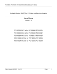
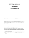
1.2 Plug&Play Installation for
Windows 95
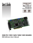
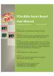
The Windows 95 support Plug&Play feature. The system will automatic detect the
PCI-series cards in the first installation and request for Plug&Play information as
shown in Fig 1. The steps for installation are given as following:
Step 1 : Place the companion floppy disk into floppy driver A
Step 2 : Select the second item in Fig 1 and select OK.
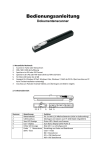
Step 3 : Select the a:\install\p1802.inf as in Fig 2.
Step 4 : Select the unique model number as in Fig 3.
Then the p1802.inf will provide all information needed to complete the installation.
After the installation, the Windows 95 will reserve the resource and build up the registry.
The Plug&Play information is shown in Fig 4. The Fig. 5 shows the resource reserved. If the
user execute the “c:\windows\regedit.exe”, the registration information of the PCI-1802H/L
will be placed under
“HKEY_LOCAL_MACHINE\System\CurrentControlSet\Service\Class\Unknown\0000”
as in Fig 6. The Fig 7 shows the registration items in detail.
Fig 1 : system request the Plug&Play information
NAPPCI/win & NAPPCI/wnt User Manual (Version 2.0) ---- 6
Fig 2. Select the A:\install\p1802.inf
Fig 3. Select the unique model number.
NAPPCI/win & NAPPCI/wnt User Manual (Version 2.0) ---- 7
Fig 4. The Plug&Play information
Fig 5. The resource reserved.
NAPPCI/win & NAPPCI/wnt User Manual (Version 2.0) ---- 8
Fig 6. The path of registration information
NAPPCI/win & NAPPCI/wnt User Manual (Version 2.0) ---- 9
Fig 7. The detail value of registration items
NAPPCI/win & NAPPCI/wnt User Manual (Version 2.0) ---- 10
1.3
C Call NAPPCI
All the demo program given in the companion floppy disk are designed with C
language. It is testing under Windows 95/NT and Visual C++ 4.0 compiler. The key
points are given as below :
1. Make sure the PATH include the Visual C++ compiler
2. Execute the \MSDEV\BIN\VCVARS32.BAT to setup the environment. The
VCVARS32.BAT is provided by Visual C++.
3. The source program must include “P1202.H”
4. Copy the P1202.LIB, import library, to the directory where same as source program
5. Copy the P1202.DLL, to the directory where same as source program
6. Edit the source program (refer to \NAPPCI\Win\VC\Demo\DEMO1.C)
(refer to \NAPPCI\Wnt\VC\Demo\DEMO1.C)
7. Edit the NMAKE file (refer to \NAPPCI\Win\VC\Demo\DEMO1.MAK)
(refer to \NAPPCI\Wnt\VC\Demo\DEMO1.MAK)
8. NMAKE /f DEMO1.MAK
9. Execute DEMO1.EXE
NOTE : The P1202.lib is used in linking time and the P1202.DLL is used in run
time.
1.4 MFC Call NAPPCI
The usage of NAPPCI for MFC user is very similar to that for C user. It tests OK
under Windows 95/NT and Visual C++ 4.0. The key points are given as below:
1.
2.
3.
4.
5.
Use MFC wizard to create source code
The source program must include “P1202.H”
Copy the P1202.LIB, import library, to the directory same as source program
Copy the P1202.DLL, to the directory same as source program
Select Build/Settings/Link and key “P1202.lib” in the object/library
modules field
NOTE : The P1202.lib is used in linking time and the P1202.DLL is used in run
time.
NAPPCI/win & NAPPCI/wnt User Manual (Version 2.0) ---- 11
1.5
BC++ Call NAPPCI
The NAPPCI is created by Visual C++ 4.0. The P1202.H and P1202.lib are also
designed for Visual C/C++. The BC++ can not use this two file. The modification part
is given below:
#include <conio.h>
#include <windows.h>
HINSTANCE hDLLLib;
// Step 1 : declare a functionpointer
float CALLBACK (*FloatSub2)(float fA, float fB);
main()
{
// Step 2 : load dll
hDllLib=LoadLibrary("P1202.dll");
if (hDLLLib)
{
// Step 3 : get the function address
FloatSub2=(FARPROC)GetProcAddress(hDLLLib,"P1202_FloatSub2");
if (FloatSub2)
{
// Step 4 : call function
printf("1.2-3.4=%f",FloatSub2(1.2,3.4);
}
else printf("get P1202_FloatSub2 function address error");
// Step 5 : free library
FreeLibrary(hDLLib);
}
else printf("load P1202.dll error");
getch();
}
This usage can be divided into
5 steps listing above. Using this
modification and P1202.DLL, the user can use BC++ to call NAPPCI.
NAPPCI/win & NAPPCI/wnt User Manual (Version 2.0) ---- 12
1.6
VB Call NAPPCI
NAPPCI\Win\VB\P1202.DLL
NAPPCI\Win\VB\FROM1.FRM
NAPPCI\Win\VB\MODULE1.BAS
NAPPCI\Win\VB\PROJECT1.VBP
" DLLs
" form and source file
" declare file
" project file
NAPPCI\Wnt\VB\P1202.DLL
NAPPCI\Wnt\VB\FROM1.FRM
NAPPCI\Wnt\VB\MODULE1.BAS
NAPPCI\Wnt\VB\PROJECT1.VBP
" DLLs
" form and source file
" declare file
" project file
NOTE : 1. Testing under Windows 95/NT and VB 4.0 (32 bits)
2. The MODULE1.BAS
is designed for demo purpose and the
MODULE1.BAS now only support “P1202_ShortSub2(A,B)”. The user can
modify this file to support all NAPPCI DLLs.
Module1.BAS
Attribute VB_Name = "Module1"
Declare Function P1202_ShortSub2 Lib "a:\NAPPCI\win\vb\P1202.dll" (ByVal a As
Integer, ByVal b As Integer) As Integer
FORM1.FRM (partial)
Private Sub Command1_Click()
Dim a As Integer, b As Integer, c As Integer
a = Val(Text1.Text)
b = Val(Text2.Text)
c = P1802_ShortSub2(a, b)
Text3.Text = c
NAPPCI/win & NAPPCI/wnt User Manual (Version 2.0) ---- 13
1.7
Delphi Call NAPPCI
NAPPCI\Win\DELPHI\P1202.PAS
NAPPCI\Win\DELPHI\P1202.DLL
NAPPCI\Win\DELPHI\UNIT1.PAS
NAPPCI\Win\DELPHI\UNIT1.DFM
NAPPCI\Win\DELPHI\PROJECT1.DPR
" unit file
" DLLs
" demo source file
" form file
" project file
NAPPCI\Wnt\DELPHI\P1202.PAS
" unit file
NAPPCI\Wnt\DELPHI\P1202.DLL
" DLLs
NAPPCI\Wnt\DELPHI\UNIT1.PAS
" demo source file
NAPPCI\Wnt\DELPHI\UNIT1.DFM
" form file
NAPPCI\Wnt\DELPHI\PROJECT1.DPR
" project file
NOTE : 1. testing under Windows 95/NT and Delphi 2.0 (32 bits)
2. The P1202.PAS is designed for demo purpose and the P1202.PAS now
only support “P1802_ShortSub2(A,B)”. The user can modify this file to
support all NAPPCI DLLs.
unit P1202;
interface
function P1202_ShortSub2(a: smallint; b: smallint): smallint; StdCall;
P1802.PAS
implementation
function P1802_ShortSub2; external 'P1202.DLL' name 'P1202_ShortSub2';
end.
procedure TForm1.Button1Click(Sender: TObject) ;
var
a,b,c : smallint;
begin
a := StrToInt(Edit1.text);
b := StrToInt(Edit2.text);
c := P1802_ShortSub2(a,b);
Edit3.text := IntToStr(c);
end;
end.
NAPPCI/win & NAPPCI/wnt User Manual (Version 2.0) ---- 14
UNIT1.PAS
(partial)
1.8
LabVIEW Call NAPPCI
LabVIEW is a industrial’s graphical programming system developed by National
Instruments. With LabVIEW, the user can quickly design the user interface and control
program as a block diagram.
NAPPCI\Win\VIEW\P1202.Dll
" DLLs
NAPPCI\Win\VIEW\DEMO1.VI
" Demo VI
NAPPCI\Win\VIEW\MFUN1.VI
" Driver VI
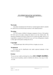
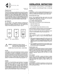
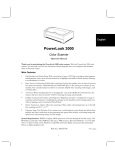
NOTE :
1. Testing under Windows 95/NT and LabVIEW 4.0
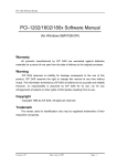
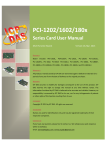
2. The demo1.VI will call MFUN1.VI to perform M_Functions. The M_Functions
can send out the arbitrary wave form to the D/A output port and perform A/D
operation at the same time. If connect the D/A channel_0 to A/D channel_0, the
D/A output can be measured back by M_Functions. The output response is shown
in Fig 8 and the connecting diagram of demo1.VI is given in Fig. 9.
3.
The NAPVIEW can support a variety of VIs designed for LabVIEW 4.0. Call
the local dealer for details.
Fig 8. The output of DEMO1.VI. (call M_FUN_1)
NAPPCI/win & NAPPCI/wnt User Manual (Version 2.0) ---- 15
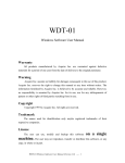
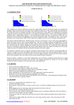
Fig 9. The connecting diagram of DEMO1.VI (call MFUN1.VI)
Fig 10. The connecting diagram of MFUN1.VI (call DLL M_FUN_1)
NAPPCI/win & NAPPCI/wnt User Manual (Version 2.0) ---- 16
1.9
Demo Program
We use a common demo program for all p1202.dll demonstration. This demo
program will accept the wDaFreq and wAdClk and call the different function for
usage demonstration.
#include <windows.h>
#include <stdlib.h>
#include <stdio.h>
#include <conio.h>
#include "P1202.H"
/***********************************************************************/
/*
DEMO1 program for one P1202 card in the PC system.
*/
/*
Please turn the resolution of your monitor at least 1024*768.
*/
/***********************************************************************/
/* First Card: some P1202 function call demo.
*/
/* For the proper operation the P1202, the following functions
*/
/* must be used.
*/
/*
P1202_DriverInit();
<-initial the driver
*/
/*
P1202_DriverClose();
<-close the driver
*/
/***********************************************************************/
short
nDMA=-1, nIRQ=-1;
// not used
WORD wBase=0x220,wAdBuf[510],wFlag=0,wAddrCtrl;
int iLine;
DWORD
dwDaNum=90,dwAdClk=24;
WORD wTotalBoard,wInitialCode;
void READ_CMD(char *);
short
ASCII_TO_HEX(char);
void TEST_CMD(HWND, int, int, int, int);
LRESULT CALLBACK WndProc(HWND, UINT, WPARAM, LPARAM);
void SHOW_WAVE(HWND hwnd);
/* -------------------------------------------------------------------- */
int WINAPI WinMain (HINSTANCE hInstance, HINSTANCE hPrevInstance,
PSTR szCmdLine, int iCmdShow)
{
static char szAppName[] = "P1202 Demo1";
HWND
hwnd ;
MSG msg ;
WNDCLASSEX wndclass ;
wndclass.cbSize
=
wndclass.style
=
wndclass.lpfnWndProc
wndclass.cbClsExtra
wndclass.cbWndExtra
wndclass.hInstance
wndclass.hIcon
=
wndclass.hCursor
=
wndclass.hbrBackground
wndclass.lpszMenuName
wndclass.lpszClassName
wndclass.hIconSm
=
sizeof(wndclass);
CS_HREDRAW|CS_VREDRAW;
= WndProc;
= 0;
= 0;
= hInstance;
LoadIcon(NULL, IDI_APPLICATION);
LoadCursor(NULL, IDC_ARROW);
= (HBRUSH)GetStockObject(WHITE_BRUSH);
= NULL;
= szAppName;
LoadIcon(NULL, IDI_APPLICATION);
NAPPCI/win & NAPPCI/wnt User Manual (Version 2.0) ---- 17
RegisterClassEx(&wndclass) ;
hwnd=CreateWindow(szAppName,"P1202 Demo1 Program",
WS_OVERLAPPEDWINDOW,
CW_USEDEFAULT, CW_USEDEFAULT,
CW_USEDEFAULT, CW_USEDEFAULT,
NULL, NULL, hInstance, NULL) ;
ShowWindow(hwnd,SW_SHOWMAXIMIZED);
UpdateWindow(hwnd);
while (GetMessage(&msg, NULL, 0, 0))
{
TranslateMessage(&msg);
DispatchMessage(&msg);
}
return msg.wParam;
}
/* -------------------------------------------------------------------- */
LRESULT CALLBACK WndProc(HWND hwnd, UINT iMsg, WPARAM wParam, LPARAM lParam)
{
static int cxChar, cyChar, cxClient, cyClient, cxBuffer, cyBuffer,
xCaret, yCaret;
static char cBuf[80];
HDC
hdc;
TEXTMETRIC
tm;
PAINTSTRUCT ps;
int
i;
switch (iMsg)
{
case WM_CREATE : // window initial
/**************************************************************/
/* NOTICE: call P1202_DriverInit() to initialize the driver. */
/**************************************************************/
// Initial the device driver, and return the board number in the PC
wInitialCode=P1202_DriverInit(&wTotalBoard);
if( wInitialCode!=NoError )
{
MessageBox(hwnd,"No P1202 card in this system !!!",
"P1202 Card Error",MB_OK);
}
hdc=GetDC(hwnd);
SelectObject(hdc,GetStockObject(SYSTEM_FIXED_FONT));
GetTextMetrics(hdc, &tm);
cxChar=tm.tmAveCharWidth;
cyChar=tm.tmHeight;
ReleaseDC(hwnd, hdc);
return 0;
case WM_SIZE :
cxClient=LOWORD(lParam);
// window size in pixels
cyClient=HIWORD(lParam);
cxBuffer=max(1,cxClient/cxChar); // window size in characters
cyBuffer=max(1,cyClient/cyChar);
return 0;
case WM_SETFOCUS :
CreateCaret(hwnd, NULL, cxChar, cyChar);
SetCaretPos(xCaret * cxChar, yCaret * cyChar);
ShowCaret(hwnd);
return 0;
case WM_KILLFOCUS :
HideCaret(hwnd);
DestroyCaret();
return 0;
NAPPCI/win & NAPPCI/wnt User Manual (Version 2.0) ---- 18
case WM_CHAR : // user press KEYBOARD
for (i = 0 ; i < (int) LOWORD(lParam) ; i++)
{
switch (wParam)
{
case '\b' :
// backspace pressed
if (xCaret > 0)
{
xCaret-- ;
cBuf[xCaret]=' ';
HideCaret(hwnd);
hdc=GetDC(hwnd);
SelectObject(hdc,GetStockObject(SYSTEM_FIXED_FONT));
TextOut(hdc, xCaret * cxChar, yCaret * cyChar,cBuf+xCaret,1);
ShowCaret(hwnd);
ReleaseDC(hwnd, hdc);
}
break;
case '\r' :
// carriage return pressed
if (wFlag==1)
{
InvalidateRect(hwnd, NULL, TRUE);
wFlag=0;
break;
}
wFlag=1;
cBuf[xCaret]=0;
if (xCaret!=0) {xCaret=0; yCaret++;}
READ_CMD(cBuf);
TEST_CMD(hwnd,xCaret, cxChar, yCaret,cyChar);
xCaret=0; yCaret+=iLine;
if (yCaret >= cyBuffer) InvalidateRect(hwnd, NULL, TRUE);
break ;
case '\x1B' :
// escape pressed
InvalidateRect (hwnd, NULL, TRUE) ;
xCaret=yCaret=0;
break;
default :
// other KEY pressed
cBuf[xCaret]=(char) wParam;
HideCaret(hwnd);
hdc=GetDC (hwnd);
SelectObject(hdc,GetStockObject(SYSTEM_FIXED_FONT));
TextOut(hdc,xCaret*cxChar,yCaret*cyChar,cBuf+xCaret,1);
ShowCaret(hwnd);
ReleaseDC(hwnd, hdc);
xCaret++;
break ;
}
}
SetCaretPos(xCaret*cxChar, yCaret*cyChar);
return 0;
case WM_PAINT :
// clr and show HELP
InvalidateRect(hwnd, NULL, TRUE);
hdc=BeginPaint(hwnd, &ps);
SelectObject(hdc,GetStockObject(SYSTEM_FIXED_FONT));
sprintf(cBuf,"Press any key to continue");
TextOut(hdc,0,0,cBuf,strlen(cBuf));
xCaret = 0 ; yCaret=1;
SetCaretPos(0,yCaret*cyChar);
EndPaint(hwnd, &ps);
return 0;
case WM_DESTROY :
NAPPCI/win & NAPPCI/wnt User Manual (Version 2.0) ---- 19
/**************************************************************/
/* NOTICE: call P1202_DriverClose() to close the driver.
*/
/**************************************************************/
P1202_DriverClose();
// close the driver
PostQuitMessage(0);
return 0 ;
}
return DefWindowProc(hwnd, iMsg, wParam, lParam);
}
/* -------------------------------------------------------------------- */
/* [0][1][2][3][4]=wII, [6][7][8][9]=dwAdClk
*/
void READ_CMD(char szCmd[])
{
DWORD nT1,nT2,nT3,nT4,nT5;
if(szCmd[0]==0) return;
// only press [Enter]
nT1=ASCII_TO_HEX(szCmd[0]);
// HEX format
nT2=ASCII_TO_HEX(szCmd[1]);
nT3=ASCII_TO_HEX(szCmd[2]);
nT4=ASCII_TO_HEX(szCmd[3]);
nT5=ASCII_TO_HEX(szCmd[4]);
dwDaNum=nT1*10000+nT2*1000+nT3*100+nT4*10+nT5;
nT1=ASCII_TO_HEX(szCmd[6]);
// HEX format
nT2=ASCII_TO_HEX(szCmd[7]);
nT3=ASCII_TO_HEX(szCmd[8]);
nT4=ASCII_TO_HEX(szCmd[9]);
dwAdClk=(DWORD)(nT1*1000+nT2*100+nT3*10+nT4);
}
short ASCII_TO_HEX(char cChar)
{
if(cChar<='9') return(cChar-'0');
else if (cChar<='F') return(cChar-'A'+10);
else return(cChar-'a'+10);
}
/* -------------------------------------------------------------------- */
void TEST_CMD(HWND hwnd, int x, int dx, int y, int dy)
{
Separate testing subroutine is putting here
}
The READ_COM only accept
fix format command. The command
format is given as below:
space key
0
1
2
wDaFreq
3
4
5
Enter key
6
7
8
wAdClk
NAPPCI/win & NAPPCI/wnt User Manual (Version 2.0) ---- 20
9
10
!
if
0
= Enter key " accept current setting of wDaFreq and wAdClk
The steps to compile and link the demo program are described in Sec. 1.3. All the
demo program share the similar interface. The separate testing subroutines are putting
in “TEST_CMD(….)
{ ……….}”. So only the TEST_CMD is listing
in user manual.
NAPPCI/win & NAPPCI/wnt User Manual (Version 2.0) ---- 21
2.
function description
These function in DLL are divided into several groups as following:
! The test functions
! The M_Functions function
! The D/I/O functions
! The D/A function
! The A/D fixed-mode functions
! The A/D MagicScan mode functions
! The A/D continuous capture functions
! The Plug&Play functions
! The Continuous-Capture functions
! The Continuous-Capture functions with storing data to main memory
!
•
The other functions
The functions of fixed-channel mode listing as follows:
1.
2.
3.
4.
•
data in float format
The functions of MagicScan mode listing as follows:
1.
2.
3.
4.
5.
•
P1202_SetChannelConfig
P1202_AdPoling
P1202_AdsPolling
P1202_AdsPacer
P1202_ClearScan
P1202_StartScan
P1202_AddToScan
P1202_SaveScan
P1202_ReadMagicScanResult
data in 12 bits HEX format
The functions of M_functions listing as follows:
1.
2.
3.
P1202_M_FUN_1
P1202_M_FUN_2
P1202_M_FUN_3
NAPPCI/win & NAPPCI/wnt User Manual (Version 2.0) ---- 22
•
The functions of continuous capture with storing data to main memory listing
as follows: (two board operating simultaneously)
1.
2.
3.
4.
•
The functions of continuous capture with storing data to main memory listing
as follows: (single board operating)
1.
2.
3.
4.
•
P180X_FunA_Start
P180X_FunA_ReadStatus
P180X_FunA_Stop
P180X_FunA_Get
P180X_FunB_Start
P180X_FunB_ReadStatus
P180X_FunB_Stop
P180X_FunB_Get
The functions of continuous capture are given as following:
1.
2.
3.
4.
5.
6.
P180X_Card0_StartScan
P180X_Card0_ReadStatus
P180X_Card0_StopScan
P180X_Card1_StartScan
P180X_Card1_ReadStatus
P180X_Card1_StopScan
Group-0: for card_0 continuous capture function
Group-1: for card_1 continuous capture function
1.
NAPPCI/win & NAPPCI/wnt User Manual (Version 2.0) ---- 23
2.1
The Configuration Code Table
PCI-1200L/1202L Configuration Code Table
Bipolar/Unipolar Input Signal Range
Gain
Settling Time
Configuration Code
Bipolar
+/- 5V
1
3 us
0x00
Bipolar
+/- 2.5V
2
3 us
0x01
Bipolar
+/- 1.25V
4
3 us
0x02
Bipolar
+/- 0.625V
8
3 us
0x03
Bipolar
+/- 10V
0.5
3 us
0x04
Bipolar
+/- 5V
1
3 us
0x05
Bipolar
+/- 2.5V
2
3 us
0x06
Bipolar
+/- 1.25V
4
3 us
0x07
Unipolar
0V ~ 10V
1
3 us
0x08
Unipolar
0V ~ 5V
2
3 us
0x09
Unipolar
0V ~ 2.5V
4
3 us
0x0A
Unipolar
0V ~ 1.25V
8
3 us
0x0B
PCI-1200H/1202H Configuration Code Table
Bipolar/Unipolar Input Signal Range
Gain
Settling Time
Configuration Code
Bipolar
+/- 5V
1
23 us
0x10
Bipolar
+/- 0.5V
10
28 us
0x11
Bipolar
+/- 0.05V
100
140 us
0x12
Bipolar
+/- 0.005V
1000
1300 us
0x13
Bipolar
+/- 10V
0.5
23 us
0x14
Bipolar
+/- 1V
5
28 us
0x15
Bipolar
+/- 0.1V
50
140 us
0x16
Bipolar
+/- 0.01V
500
1300 us
0x17
Unipolar
0V ~ 10V
1
23 us
0x18
Unipolar
0V ~ 1V
10
28 us
0x19
Unipolar
0V ~ 0.1V
100
140 us
0x1A
Unipolar
0V ~ 0.01V
1000
1300 us
0x1B
NAPPCI/win & NAPPCI/wnt User Manual (Version 2.0) ---- 24
2.2
P1202.H
#define EXPORTS extern "C" __declspec (dllimport) // Usage for Allpication
// #define EXPORTS
// Usage for DLL
//----------priority setting constant---------------------------------//
//
THREAD_PRIORITY_LOWEST
//
THREAD_PRIORITY_BELOW_NORMAL
//
THREAD_PRIORITY_NORMAL
//
THREAD_PRIORITY_ABOVE_NORMAL
//
THREAD_PRIORITY_HIGHEST
//
//----------priority setting constant---------------------------------// return code
#define NoError
0
#define DriverHandleError
1
#define DriverCallError
2
#define AdControllerError
3
#define M_FunExecError
4
#define ConfigCodeError
5
#define FrequencyComputeError 6
#define HighAlarm
7
#define LowAlarm
8
#define AdPollingTimeOut
9
#define AlarmTypeError
10
#define FindBoardError
11
#define AdChannelError
12
#define DaChannelError
13
#define InvalidateDelay
14
#define DelayTimeOut
15
#define InvalidateData
16
#define FifoOverflow
17
#define TimeOut
18
#define ExceedBoardNumber
19
#define NotFoundBoard
20
#define OpenError
21
#define FindTwoBoardError
22
#define ThreadCreateError
23
#define StopError
24
#define AllocateMemoryError 25
EXPORTS float CALLBACK P1202_FloatSub2(float fA, float fB);
EXPORTS short CALLBACK P1202_ShortSub2(short nA, short nB);
EXPORTS WORD CALLBACK P1202_GetDllVersion(void);
EXPORTS WORD CALLBACK P1202_DriverInit(WORD *wTotalBoards);
EXPORTS void CALLBACK P1202_DriverClose(void);
EXPORTS WORD CALLBACK P1202_GetDriverVersion(WORD *wVxdVersion);
EXPORTS WORD CALLBACK P1202_GetConfigAddressSpace(WORD wBoardNo,
WORD *wAddrTimer,WORD *wAddrCtrl, WORD *wAddrDio, WORD *wAddrAdda);
EXPORTS WORD CALLBACK P1202_ActiveBoard( WORD wBoardNo );
NAPPCI/win & NAPPCI/wnt User Manual (Version 2.0) ---- 25
EXPORTS WORD CALLBACK P1202_WhichBoardActive(void);
EXPORTS WORD CALLBACK P1202_M_FUN_1(WORD wDaFrequency, WORD wDaWave,
float fDaAmplitude, WORD wAdClock, WORD wAdNumber,
WORD wAdConfig, float fAdBuf[],
float fLowAlarm, float fHighAlarm);
EXPORTS WORD CALLBACK P1202_M_FUN_2(WORD wDaNumber, WORD wDaWave,
WORD wDaBuf[], WORD wAdClock, WORD wAdNumber,
WORD wAdConfig, WORD wAdBuf[]);
EXPORTS WORD CALLBACK P1202_M_FUN_3(WORD wDaFrequency, WORD wDaWave,
float fDaAmplitude, WORD wAdClock, WORD wAdNumber,
WORD wChannelStatus[], WORD wAdConfig[],
float fAdBuf[], float fLowAlarm, float fHighAlarm);
EXPORTS WORD CALLBACK P1202_M_FUN_4(WORD wType, WORD wDaFrequency, WORD
wDaWave,
float fDaAmplitude, WORD wAdClock, WORD wAdNumber,
WORD wChannelStatus[], WORD wAdConfig[],
float fAdBuf[], float fLowAlarm, float fHighAlarm);
EXPORTS WORD CALLBACK P1202_Di(WORD *wDi);
EXPORTS WORD CALLBACK P1202_Do(WORD wDo);
EXPORTS WORD CALLBACK P1202_Da(WORD wDaChannel, WORD wDaVal);
EXPORTS WORD CALLBACK P1202_SetChannelConfig(WORD wAdChannel,
WORD wConfig);
EXPORTS WORD CALLBACK P1202_AdPolling(float *fAdVal);
EXPORTS WORD CALLBACK P1202_AdsPolling(float fAdVal[], WORD wNum);
EXPORTS WORD CALLBACK P1202_AdsPacer(float fAdVal[], WORD wNum,
WORD wSample);
EXPORTS WORD CALLBACK P1202_ClearScan(void);
EXPORTS WORD CALLBACK P1202_StartScan(WORD wSampleRateDiv, DWORD dwNum,
SHORT nPriority);
EXPORTS void CALLBACK P1202_ReadScanStatus(WORD *wStatus,
DWORD *dwLowAlarm, DWORD *dwHighAlarm);
EXPORTS WORD CALLBACK P1202_AddToScan(WORD wAdChannel, WORD wConfig,
WORD wAverage, WORD wLowAlarm, WORD wHighAlarm,
WORD wAlarmType);
EXPORTS WORD CALLBACK P1202_SaveScan(WORD wAdChannel, WORD wBuf[]);
EXPORTS void CALLBACK P1202_WaitMagicScanFinish(WORD *wStatus,
DWORD *dwLowAlarm, DWORD *dwHighAlarm);
EXPORTS WORD CALLBACK P1202_StopMagicScan();
EXPORTS WORD CALLBACK P1202_DelayUs(WORD wDelayUs);
EXPORTS WORD CALLBACK P1202_Card0_StartScan(WORD wSampleRate, WORD
wChannelStatus[],
WORD wChannelConfig[],WORD wCount);
EXPORTS WORD CALLBACK P1202_Card0_ReadStatus(WORD wBuf[], WORD wBuf2[],
DWORD *dwP1, DWORD *dwP2,
WORD *wStatus);
EXPORTS void CALLBACK P1202_Card0_Stop(void);
NAPPCI/win & NAPPCI/wnt User Manual (Version 2.0) ---- 26
EXPORTS WORD CALLBACK P1202_Card1_StartScan(WORD wSampleRate,
WORD wChannelStatus[],WORD wChannelConfig[],WORD wCount);
EXPORTS WORD CALLBACK P1202_Card1_ReadStatus(WORD wBuf[], WORD wBuf2[],
DWORD *dwP1, DWORD *dwP2,WORD *wStatus);
EXPORTS void CALLBACK P1202_Card1_Stop(void);
EXPORTS WORD
WORD
WORD
WORD
EXPORTS WORD
EXPORTS WORD
EXPORTS WORD
CALLBACK P1202_FunA_Start(WORD wClock0Div, WORD wChannel0[],
wConfig0[], WORD *Buffer0, DWORD dwMaxCount0,
wClock1Div, WORD wChannel1[],WORD wConfig1[],
*Buffer1, DWORD dwMaxCount1, SHORT nPriority);
CALLBACK P1202_FunA_ReadStatus(void);
CALLBACK P1202_FunA_Stop(void);
CALLBACK P1202_FunA_Get(DWORD *P0, DWORD *P1);
EXPORTS WORD
WORD
EXPORTS WORD
EXPORTS WORD
EXPORTS WORD
CALLBACK P1202_FunB_Start(WORD wClock0Div, WORD wChannel0[],
wConfig0[], WORD *Buffer0, DWORD dwMaxCount0, SHORT nPriority);
CALLBACK P1202_FunB_ReadStatus(void);
CALLBACK P1202_FunB_Stop(void);
CALLBACK P1202_FunB_Get(DWORD *P0);
EXPORTS WORD CALLBACK P1202_MemoryStatus(DWORD *dwTotalPhys,
DWORD *dwAvailPhys, DWORD *dwTotalPageFile,
DWORD *dwAvailPageFile, DWORD *dwTotalVirtual,
DWORD *dwAvailVirtual);
EXPORTS WORD CALLBACK P1202_AllocateMemory(HGLOBAL *hMem, WORD *Buffer,
DWORD dwSize);
EXPORTS WORD CALLBACK P1202_FreeMemory(HGLOBAL hMem);
EXPORTS WORD CALLBACK P1202_StartScanPostTrg(WORD wSampleRateDiv,
DWORD dwNum, SHORT nPriority);
EXPORTS WORD CALLBACK P1202_StartScanPreTrg(WORD wSampleRateDiv,
DWORD dwNum, SHORT nPriority);
EXPORTS WORD CALLBACK P1202_StartScanMiddleTrg(WORD wSampleRateDiv,
DWORD dwN1, DWORD dwN2, SHORT nPriority);
EXPORTS WORD CALLBACK P1202_StartScanPreTrgVerC(WORD wSampleRateDiv,
DWORD dwNum, SHORT nPriority);
EXPORTS WORD CALLBACK P1202_StartScanMiddleTrgVerC(WORD wSampleRateDiv,
DWORD dwN1, DWORD dwN2, SHORT nPriority);
NAPPCI/win & NAPPCI/wnt User Manual (Version 2.0) ---- 27
2.3
The Testing Functions
2.3.1
P1202_FloatSub2
!
Description:
Compute C=A-B in float format, float=4 bytes floating point number. This function is
provided to test DLL linkage.
•
!
Syntax: float P1202_FloatSub2(float fA, float fB);
Input Parameter :
fA : 4 bytes floating point value
fB : 4 bytes floating point value
!
!
Return Value : return=fA-fB
Demo Program : DEMO1.C
2.3.2
!
P1202_ShortSub2
Description :
Compute C=A-B in SHORT format, SHORT=16 bits signed number. This function is
provided to test DLL linkage.
•
!
Syntax : short P1202_ShortSub2(Short nA, Short nB);
Input Parameter :
nA : 16 bits value
nB : 16 bits value
!
!
Return Value : return=nA-nB
Demo Program : DEMO1.C
NAPPCI/win & NAPPCI/wnt User Manual (Version 2.0) ---- 28
2.3.3
!
P1202_GetDllVersion
Description :
Read the DLL version number of the P1202.DLL.
!
Syntax : WORD P1202_GetDllVersion(void);
!
Input Parameter : void
!
Return Value :
return=0x200 " Version 2.0
!
Demo Program : DEMO1.C
2.3.4
!
P1202_GetDriverVersion
Description : This subroutine will read the software version number of
NAPPCI.VxD of Windows 95 or NAPPCI.SYS of Windows NT.
!
Syntax : WORD P1202_GetDriverVersion(WORD *wDriverVersion);
!
Input Parameter : *wDriverVersion : address of wDriverVersion
wDriverVersion=0x200 " Version 2.0
!
Return Value :
NoError : OK
DriverHandleError : the NAPPCI.VxD open error for Windows 95
the NAPPCI.SYS open error for Windows NT
DriverCallError : call NAPPCI.VxD return error
call NAPPCI.SYS return error
!
Demo Program : DEMO1.C
NAPPCI/win & NAPPCI/wnt User Manual (Version 2.0) ---- 29
2.4
The M_Functions
2.4.1
P1202_M_FUN_1
!
Description :
The P1202_M_FUN_1 will compute the wave form image automatically. (Refer to “PCI1800/1802 Hardware Manual” chapter-5 for details) (input=AD channel_0, output=DA
channel_0)
•
Syntax :
WORD P1202_M_FUN_1(WORD wDaFrequency, WORD wDaWave, float
fDaAmplitude, WORD wAdClock, WORD wAdNumber, WORD wAdConfig,
float fAdBuf[], float fLowAlarm, float fHighAlarm)
!
Input Parameter :
wDaFrequency : DA output frequency = 1.8M/wDaFrequency (pentium 120)
wDaWave : Number of DA wave form to be output
fDaAmplitude : Amplitude of DA output. NOTE : the hardware J1 must select +/-10V
wAdClock : AD sampling clock = 8000000/wAdClock samples/sec
wAdNumber: Number of AD data to be read
wAdConfig : A/D input range configuration code
fAdBuf[] : the starting address of fAdBuf which store the A/D data
fLowAlarm : low alarm limit. if fAdBuf[?]< fLowAlarm " LowAlarm
fHighAlarm : high alarm limit. if fAdBuf[?]>fHighAlarm " HighAlarm
!
Return Value :
NoError : OK
DriverHandleError : Invalidate VxD/SYS handle
DriverCallError : VxD/SYS function call error
ExceedBoardNumber: invalidate board number
FindBoardError: no PCI-1800/1802 board
AdControllerError : embedded controller handshake error
M_FunExecError : M_Functions return code error
ConfigCodeError : wAdConfig configuration code error
HighAlarm : fAdBuf[?]>fHighAlarm
LowAlarm : fAdBuf[?]< fLowAlarm
!
Demo Program : DEMO5.C
NAPPCI/win & NAPPCI/wnt User Manual (Version 2.0) ---- 30
2.4.2
!
P1202_M_FUN_2
Description :
The P1202_M_FUN_2 will not compute the wave form image automatically. (Refer to
“PCI-1800/1802 Hardware Manual” chapter-5 for details) (input=AD channel_0, output=DA
channel_0)
•
Syntax :
WORD P1202_M_FUN_2(WORD wDaNumber, WORD wDaWave, WORD wDaBuf[],
WORD wAdClock, WORD wAdNumber, WORD wAdConfig, WORD
wAdBuf[]);
!
Input Parameter :
wDaNumber: number of D/A samples in one wave form
wDaWave : Number of DA wave form to be output
wDaBuf[] : The array store the D/A wave form image
wAdClock : AD sampling clock = 8000000/wAdClock samples/sec
wAdNumber: Number of AD data to be read
wAdConfig : A/D input range configuration code.
wAdBuf[] : the starting address of fAdBuf which store the A/D data
!
Return Value :
NoError : OK
DriverHandleError : Invalidate VxD/SYS handle
DriverCallError : VxD/SYS function call error
ExceedBoardNumber: invalidate board number
FindBoardError: no PCI-1800/1802 board
AdControllererror : embedded controller handshake error
M_FunExecError : M_Functions return code error
ConfigCodeError : wAdConfig configuration code error
!
Demo Program : DEMO7.C
machine dependent function.
1.8M/wDaNumber is machine dependent. The
The DA output wave form generator is a
The DA output frequency =
testing results are given as follows:
DA output frequency = 1.8M/dwDaNumber for pentium 120
DA output frequency = 2.0M/dwDaNumber for pentium 133
The user must test this value before using M_FUN_1,
M_FUN_2 and M_FUN_3.
NAPPCI/win & NAPPCI/wnt User Manual (Version 2.0) ---- 31
2.4.3
!
P1202_M_FUN_3
Description :
The P1202_M_FUN_3 will compute the wave form image automatically. (Refer to “PCI1800/1802 Hardware Manual” chapter-5 for details) (input=programable channels, output=DA
channel_0) This function will refer to the current active PCI-1800/1802 board. Use the
P1202_ActiveBoard(….) to select the active board. Refer to Sec. 2.4.2 for more information.
!
Syntax :
WORD P1202_M_FUN_3(WORD wDaFrequency, WORD wDaWave, float
fDaAmplitude,
WORD
wAdClock,
WORD
wAdNumber,
WORD
wChannelStatus[], WORD wAdConfig[], float fAdBuf[], float fLowAlarm, float
fHighAlarm)
!
Input Parameter :
wDaFrequency : DA output frequency = 1.8M/wDaFrequency (pentium 120)
wDaWave : Number of DA wave form to be output
fDaAmplitude : Amplitude of DA output. NOTE : the hardware J1 must select +/-10V
wAdClock : AD sampling clock = 8000000/wAdClock samples/sec
wAdNumber: Number of AD data to be read
wAdChannel[]: 1=scan, 0=no scan
wAdConfig[]: configuration code
fAdBuf[] : the starting address of fAdBuf which store the A/D data
fLowAlarm : low alarm limit. if fAdBuf[?]< fLowAlarm " LowAlarm
fHighAlarm : high alarm limit. if fAdBuf[?]>fHighAlarm " HighAlarm
!
Return Value :
NoError : OK
DriverHandleError : Invalidate VxD/SYS handle
DriverCallError : VxD/SYS function call error
ExceedBoardNumber: invalidate board number
FindBoardError: no PCI-1800/1802 board
AdControllerError : embedded controller handshake error
M_FunExecError : M_Functions return code error
ConfigCodeError : wAdConfig configuration code error
HighAlarm : fAdBuf[?]>fHighAlarm
LowAlarm : fAdBuf[?]< fLowAlarm
• Demo Program : DEMO9.C
NAPPCI/win & NAPPCI/wnt User Manual (Version 2.0) ---- 32
2.5
The DIO Functions
2.5.1
P1202_Di
!
Description :
This subroutine will read the 16 bits data from DI port. This function
will refer to the current active PCI-1202. Use the P1202_ActiveBoard(….) to select the
active board.
!
!
Syntax : WORD P1202_Di(WORD *wDi);
Input Parameter :
*wDi : address of wDi which store the 16 bits DI data
!
Return Value :
NoError : OK
FindBoardError : cannot find the PCI-1800/1802 board
ExceedBoardNumber: invalidate board number
!
Demo Program : DEMO1.C
2.5.2
!
P1202_Do
Description :
This subroutine will send the 16 bits data to DO port. This function
will refer to the current active PCI-1800/1802 board. Use the P1202_ActiveBoard(….) to
select the active board.
!
!
Syntax : WORD P1202_Do(WORD wDo);
Input Parameter :
wDo : the 16 bits data sent to DO port
!
Return Value :
NoError : OK
ExceedBoardNumber: invalidate board number
FindBoardError : cannot find the PCI-1800/1802 board
!
Demo Program : DEMO1.C
NAPPCI/win & NAPPCI/wnt User Manual (Version 2.0) ---- 33
2.6
The DA Functions
2.6.1
P1202_Da
Description :
This subroutine will send the 12 bits data to DA port. This function
will refer to the current active PCI-1202 board. Use the P1202_ActiveBoard(….) to select the
active board.
!
!
Syntax : WORD P1202_Da(WORD wChannel, WORD wDaVal);
Input Parameter :
wChannel : 0 for channel_0 DA, 1 for channel_1 DA
wDaVal : 12 bits data sent to DA port. 0=minimum and 4095=maximum. The DA
output can be +/- 5V or +/- 10V setting by hardware JP1. The software can’t
detect the state of JP1. So 4095 maybe +5V or +10V (depend on JP1).
!
Return Value :
NoError : OK
FindBoardError : cannot find the PCI-1800/1802 board
ExceedBoardNumber: invalidate board number
DaChannelError : channel number must be 0 or 1
!
Demo Program : DEMO1.C
NAPPCI/win & NAPPCI/wnt User Manual (Version 2.0) ---- 34
2.7 The AD Fixed-mode Functions
2.7.1
!
P1202_SetChannelConfig
Description :
This subroutine will set the AD channel’s configuration code. This
subroutine will set the active AD channel for P1202_AdPolling, P1202_AdsPolling and
P1202_AdsPacer. This function will refer to the current active PCI-1202 board. Use the
P1202_ActiveBoard(….) to select the active board.
!
!
Syntax : WORD P1202_SetChannelConfig(WORD wChannel, WORD wConfig);
Input Parameter :
wChannel : AD channel number
wConfig : Configuration code. Refer to “PCI-1800/1802 Hardware Manual” for details.
!
Return Value :
NoError : OK
ExceedBoardNumber: invalidate board number
FindBoardError : cannot find the PCI-1800/1802 board
AdControllerError : MagicScan controller hardware handshake error
!
Demo Program : DEMO1.C
2.7.2
!
P1202_AdPolling
Description :
This subroutine will perform the AD conversion by polling one time.
The P1202_SetChannelConfig subroutine can be used to change channel or
configuration code and the P1202_AdPolling will refer to that condition in later
operation. This function will refer to the current active PCI-1202 board. Use the
P1202_ActiveBoard(….) to select the active board.
!
!
Syntax : WORD P1202_AdPolling(float *fAdVal);
Input Parameter :
*fAdVal : address of fAdVal which store the AD data, this data is automatically
computed based on the setting of P1202_SetChannelConfig.
!
Return Value :
NoError : OK
ExceedBoardNumber: invalidate board number
FindBoardError : cannot find the PCI-1800/1802 board
AdPollingTimeOut : hardware timeout error
!
Demo Program : DEMO1.C
NAPPCI/win & NAPPCI/wnt User Manual (Version 2.0) ---- 35
2.7.3
!
P1202_AdsPolling
Description : This subroutine will perform multiple AD conversions by polling. The
P1202_SetChannelConfig subroutine can be used to change channel or configuration
code and the P1202_AdsPolling will refer to that condition in later operation. This
function will refer to the current active PCI-1202 board. Use the P1202_ActiveBoard(….)
to select the active board.
!
!
Syntax : WORD P1202_AdsPolling(float fAdVal[], WORD wNum);
Input Parameter :
fAdVal[]: starting address of AD data buffer, these data will be automatically
computed based on the setting of P1202_SetChannelConfig.
wNum: number of AD conversions will be performed.
• Return Value :
NoError: OK
ExceedBoardNumber: invalidate board number
FindBoardError: cannot find the PCI-1800/1802 board
AdPollingTimeOut: hardware timeout error
!
Demo Program : DEMO1.C
NAPPCI/win & NAPPCI/wnt User Manual (Version 2.0) ---- 36
2.7.4
!
P1202_AdsPacer
Description :
This subroutine will perform multiple AD conversions by pacer
trigger. The P1202_SetChannelConfig subroutine can be used to change channel or
configuration code and the P1202_AdsPacer will refer to that condition in later operation.
The hardware pacer will generate trigger signal to AD converter periodically. So these AD
data can be used to reconstruct the wave form of analog input. The P1202_AdsPolling is
controlled by software polling , so the AD conversion operation will be interrupted by
system OS. It is recommended to use
P1202_AdsPacer if the input
wave form reconstruction is needed. This function will refer to the current active
PCI-1202 board. Use the P1202_ActiveBoard(….) to select the active board.
!
Syntax : WORD P1202_AdsPacer(float fAdVal[], WORD wNum, WORD wSample);
!
Input Parameter :
fAdVal[] : starting address of AD data buffer, these data will be automatically
computed based on the setting of P1202_SetChannelConfig.
wNum : number of AD conversions will be performed.
wSample : AD
sampling rate = 8M/wSample.
wSample=24 " sampling rate=8M/24=333K " maximum
wSample=80 " sampling rate=8M/80=100K
!
Return Value :
NoError : OK
ExceedBoardNumber: invalidate board number
FindBoardError : cannot find the PCI-1202 board
AdPollingTimeOut : hardware timeout error
!
Demo Program : DEMO1.C
P1202_SetChannelConfig
P1202_AdPolling
P1202_AdsPollng
P1202_AdsPacer
Fix channel AD conversion mode
NAPPCI/win & NAPPCI/wnt User Manual (Version 2.0) ---- 37
2.8
The MagicScan Functions
2.8.1
P1202_ClearScan
!
Description :
This subroutine will initialize the MagicScan controller to the Initial
state. This function will refer to the current active PCI-1202 board. Use the
P1202_ActiveBoard(….) to select the active board.
!
!
!
Syntax : WORD P1202_ClearScan();
Input Parameter : void
Return Value :
NoError : OK
ExceedBoardNumber: invalidate board number
FindBoardError : cannot find the PCI-1202 board
AdControllerError : MagicScan controller hardware handshake error
! Demo Program : DEMO11.C
NAPPCI/win & NAPPCI/wnt User Manual (Version 2.0) ---- 38
2.8.2
!
P1202_StartScan
Description : This subroutine will start the MagicScan operation. This
subroutine will return to the caller before the MagicScan
operation finished. The user can use P1202_WaitMagicScanFisish(…) or
P1202_ReadScanStatus(…) to check the state of MagicScan operation. This
function will refer to the current active PCI-1202 board. Use the
P1202_ActiveBoard(….) to select the active board.
!
!
Syntax : WORD P1202_StartScan(WORD wSampleRate, WORD wNum);
Input Parameter :
wSampleRate : AD sampling rate = 8M/wSampleRate.
wSampleRate=24 " sampling rate=8M/24=333K " maximum
wSampleRate=80 " sampling rate=8M/80=100K
wNum : Number of MagicScan cycle to perform
!
Return Value :
NoError : OK
ExceedBoardNumber: invalidate board number
FindBoardError : cannot find the PCI-1202 board
AdControllerError : MagicScan controller hardware handshake error
!
Demo Program : DEMO11.C
NAPPCI/win & NAPPCI/wnt User Manual (Version 2.0) ---- 39
2.8.3
!
P1202_ReadScanStatus
Description : This subroutine will read the status of
the MagicScan operation. This
function will refer to the current active PCI-1202 board. Use the P1202_ActiveBoard(….)
to select the active board.
!
Syntax : void P1202_ReadScanStatus(WORD *wStatus, WORD
*wLowAlarm, WORD *wHighAlarm);
!
Input Parameter :
*wStatus : address of wStatus which store the MagicScan status
*wLowAlarm : address of wLowAlarm which store the MagicScan alarm status
*wHighAlarm : address of wHighAlarm which store the MagicScan alarm status
! Return Value : void
!
Demo Program : DEMO11.C
wStatus
= 0x00
= 0x01
= 0x02
= 0x04
= 0x08
= 0x80
" MagicScan initial condition (idle state)
" MagicScan start to operation
" MagicScan stage 1 controller timeout
" MagicScan stage 2 controller timeout
" MagicScan FIFO overflow
" MagicScan function OK
" 32 bits corresponding to 32 channels
" 0 = no low alarm
" 1 = is low alarm
wLowAlarm=0 " all channels OK, no low alarm
wLowAlarm=1 " channel_0 is low alarm, others are OK
wLowAlarm=3 " channel_0 and channel_1 are low alarm, others are OK
wLowAlarm
wHighAlarm
wHighAlarm=0
wHighAlarm=1
wHighAlarm=3
OK
" 32 bits corresponding to 32 channels
" 0 = no high alarm
" 1 = is high alarm
" all channels OK, no high alarm
" channel_0 is high alarm, others are OK
" channel_0 and channel_1 are high alarm, others are
NAPPCI/win & NAPPCI/wnt User Manual (Version 2.0) ---- 40
2.8.4
!
P1202_AddToScan
Description :
This subroutine will add one channel to the MagicScan circular
queue. This function will refer to the current active PCI-1800/1802 board. Use the
P1202_ActiveBoard(….) to select the active board.
!
Syntax : void P1202_AddToScan(WORD wAdChannel, WORD wConfig, WORD
wAverage, WORD wLowAlarm, WORD wHighAlarm, WORD wAlarmType);
!
Input Parameter :
wAdChannel : AD channel number
wConfig : the configuration code
wAverage : the factor of digital average filter
wLowAlarm : 12 bits low alarm data
wHighAlarm : 12 bits high alarm data
wAlarmType : 0=no alarm, 1=high alarm, 2=low alarm, 3=in-alarm, 4=out-alarm
! Return Value : void
NoError : Ok
ExceedBoardNumber: invalidate board number
FindBoardError : cannot find the PCI-1800/1802 board
AdChannelError : invalidate AD channel
AlarmTypeError : only 0/1/2/3/4 are validate
AdControllerError : MagicScan controller hardware handshake error
!
Demo Program : DEMO11.C
NAPPCI/win & NAPPCI/wnt User Manual (Version 2.0) ---- 41
2.8.5
!
P1202_SaveScan
Description : This subroutine will specify the starting address of AD data buffer for
MagicScan.
!
!
Syntax : void P1202_SaveScan(WORD wAdChannel, WORD wBuf[]);
Input Parameter :
wAdChannel : Scan number in the scan
queue.
(Note: not the A/D channel number.)
!
wBuf : starting address of AD data buffer for channel specified in wAdChannel
Return Value :
NoError : Ok
ExceedBoardNumber: invalidate board number
FindBoardError : cannot find the PCI-1800/1802 board
AdChannelError : invalidate AD channel
!
Demo Program :.DEMO11.C
NAPPCI/win & NAPPCI/wnt User Manual (Version 2.0) ---- 42
2.8.6
!
P1202_WaitMagicScanFinish
Description :
This subroutine will wait until the MagicScan operation is finished.
This function will refer to the current active PCI-1800/1802 board. Use the
P1202_ActiveBoard(….) to select the active board.
!
Syntax : void P1202_WaitMagicScanFinish(WORD *wStatus, WORD
*wLowAlarm, WORD *wHighAlarm);
!
Input Parameter :
!
*wStatus : address of wStatus which store the MagicScan status
*wLowAlarm : address of wLowAlarm which store the MagicScan alarm status
*dwHighAlarm : address of wHighAlarm which store the MagicScan alarm status
Return Value : void
!
Demo Program : DEMO11.C
wStatus
= 0x00
= 0x01
= 0x02
= 0x04
= 0x08
= 0x80
wLowAlarm
wLowAlarm=0
wLowAlarm=1
wLowAlarm=3
" MagicScan initial condition (idle state)
" MagicScan start to operation
" MagicScan stage 1 controller timeout
" MagicScan stage 2 controller timeout
" MagicScan FIFO overflow
" MagicScan function OK
" 32 bits corresponding to 32 channels
" 0 = no low alarm
" 1 = is low alarm
" all channels OK, no low alarm
" channel_0 is low alarm, others are OK
" channel_0 and channel_1 are low alarm, others are OK
" 32 bits corresponding to 32 channels
" 0 = no high alarm
" 1 = is high alarm
wHighAlarm=0
" all channels OK, no high alarm
wHighAlarm=1 " channel_0 is high alarm, others are OK
wHighAlarm=3
" channel_0 and channel_1 are high alarm, others are OK
wHighAlarm
NAPPCI/win & NAPPCI/wnt User Manual (Version 2.0) ---- 43
2.9
The Pulg&Play Functions
2.9.1
P1202_DriverInit
!
Description :
Return all resources to system. This function must be called once
before program is terminated.
!
Syntax : WORD P1202_DriverInit(WORD *wTotalBoard);
!
Input Parameter : *wTotalBoard: address of wTotalBoard
wTotalBoard=1 " one PCI-1800/1802 card in the system
wTotalBoard=n " n*PCI-1800/1802 cards in the system
!
Return Value :
NoError : OK
NoFoundBoard: detect no PCI-1800/1802
FindBoardError: handshake check error
DriverHandleError : the NAPPCI.VxD .open error for Windows 95
the NAPPCI.SYS .open error for Windows NT
DriverCallError : call NAPPCI.VxD return error
call NAPPCI.SYS return error
!
Demo Program : All DEMO program.
2.9.2
!
P1202_DriverClose
Description : This function will detect all the PCI-1800/1802 boards installed in the
system. This function must be called once before the other functions are called.
!
!
!
!
Syntax : void P1202_DriverClose(void);
Input Parameter : void
Return Value : void
Demo Program : All DEMO program.
NAPPCI/win & NAPPCI/wnt User Manual (Version 2.0) ---- 44
2.9.3
!
P1202_GetConfigAddressSpace
Description : Get the I/O address of PCI-1800/1802 board n. This function is
for debug. It is not necessary to call this function.
!
Syntax : WORD P1202_GetConfigAddressSpace(WORD wBoardNo, WORD
*wAddrTimer,WORD *wAddrCtrl, WORD *wAddrDio, WORD *wAddrAdda);
!
Input Parameter :
wBoardNo: PCI-1800/1802 board number
wAddrTimer, wAddrCtrl, wAddrDio, wAddrAdda: refer to “PCI-1800/1802
Hardware manual” chapter-3 for details.
!
Return Value :
NoError : OK
FindBoardError: handshake check error
ExceedBoardError: wBoardNo is invalidate
!
Demo Program : DEMO1.C
2.9.4
!
!
!
!
!
P1202_WhichBoardActive
Description: Return the board number of the active board.
Syntax: WORD P1202_WhichBoardActive(void);
Input Parameter: void
Return Value: board number of the active board.
Demo Program: DEMO1.C
NAPPCI/win & NAPPCI/wnt User Manual (Version 2.0) ---- 45
2.9.5
!
P1202_ActiveBoard
Description: This function will active one of the PCI-1800/1802 boards installed in
the system. This function must call once before the D/I/O, A/D, D/A functions are called.
!
Syntax: WORD P1202_ActiveBoard(WORD wBoardNo);
!
Input Parameter:
wBoardNo: board number
!
Return Value :
NoError : OK
ExceedBoardError: wBoardNo is invalidate
!
Demo Program : All DEMO program.
The P1202_ActiveBoard(…) will take effect on all functions except the following:
1. P1202_FloatSub2
2. P1202_ShortSub2
3. P1202_GetDriverVersion
4. P1202_DriveInit
5. P1202_DriveClose
6. P1202_GetConfigAddressSpace
7. P1202_Card0_StartScan
8. P1202_Card0_ReadData
9. P1202_Card0_Stop
10. P1202_Card1_StartScan
11. P1202_Card1_ReadData
12. P1202_Card1_Stop
NAPPCI/win & NAPPCI/wnt User Manual (Version 2.0) ---- 46
2.10 The Continuous Capture Functions
2.10.1
!
P1202_Card0_StartScan
Description :
This subroutine will start the continuous capture function.
Refer to “PCI-1800/1802 Hardware User Manual chapter-6 for details”
!
Syntax : WORD P1202_Card0_StartScan(WORD wSampleRate, WORD
wChannelStatus[], WORD wChanelConfig[], WORD wCount);
!
Input Parameter :
wSampleRate : AD sampling rate = 8M/wSampleRate.
wSampleRate=24 " sampling rate=8M/24=333K " maximum
wSampleRate=80 " sampling rate=8M/80=100K
wChannelStatus[]: (0=no scan, 1=scan) for each channel
wChannelConfig[]: configuration code for each channel
wCount: number of A/D data for each scan channel
!
Return Value :
NoError : OK
FindBoardError : cannot find the PCI-1800/1802 board
AdControllerError : MagicScan controller hardware handshake error
!
Demo Program : DEMO13.C
NAPPCI/win & NAPPCI/wnt User Manual (Version 2.0) ---- 47
2.10.2
!
P1202_Card0_ReadStatus
Description :
This subroutine will read the data of continuous capture
function.
!
Syntax : P1202_Card0_ReadStatus(WORD wBuf[], WORD wBuf2[],
DWORD *dwP1, DWORD *dwP2, WORD *wStatus);
!
Input Parameter :
wBuf[]: in scan sequence order(012…N012…N……012…N)
wBuf2[]: in channel sequence order(00000…..11111……22222….NNNNN….)
dwP1: reserved
dwP2: reserved
wStatus: 1=thread start, 2=TimeOut, 8=FIFO overflow, 0x80=thread finish
!
Return Value :
0: data is ready
1: data not ready
!
Demo Program : DEMO13.C
2.10.3
!
!
!
!
!
P1202_Card0_Stop
Description : This subroutine will stop the continuous capture function.
Syntax : void P1202_Card0_Stop(void);
Input Parameter :void
Return Value :void
Demo Program : DEMO13.C
NAPPCI/win & NAPPCI/wnt User Manual (Version 2.0) ---- 48
2.10.4
!
P1202_Card1_StartScan
Description :
This subroutine will start the continuous capture function.
Refer to “PCI-1800/1802 Hardware User Manual chapter-6 for details”
!
Syntax : WORD P1202_Card1_StartScan(WORD wSampleRate, WORD
wChannelStatus[], WORD wChanelConfig[], WORD wCount);
!
Input Parameter :
wSampleRate : AD sampling rate = 8M/wSampleRate.
wSampleRate=24 " sampling rate=8M/24=333K " maximum
wSampleRate=80 " sampling rate=8M/80=100K
wChannelStatus[]: (0=no scan, 1=scan) for each channel
wChannelConfig[]: configuration code for each channel
wCount: number of A/D data for each scan channel
!
Return Value :
NoError : OK
FindBoardError : cannot find the PCI-1800/1802 board
AdControllerError : MagicScan controller hardware handshake error
!
Demo Program : DEMO14.C
NAPPCI/win & NAPPCI/wnt User Manual (Version 2.0) ---- 49
2.10.5
!
P1202_Card1_ReadStatus
Description :
This subroutine will read the data of continuous capture
function.
!
Syntax : P1202_Card0_ReadStatus(WORD wBuf[], WORD wBuf2[],
DWORD *dwP1, DWORD *dwP2, WORD *wStatus);
!
Input Parameter :
wBuf[]: in scan sequence order(012…N012…N……012…N)
wBuf2[]: in channel sequence order(00000…..11111……22222….NNNNN….)
dwP1: reserved
dwP2: reserved
wStatus: 1=thread start, 2=TimeOut, 8=FIFO overflow, 0x80=thread finish
!
Return Value :
0: data is ready
1: data not ready
!
Demo Program : DEMO14.C
2.10.6
!
!
!
!
!
P1202_Card1_Stop
Description : This subroutine will stop the continuous capture function.
Syntax : void P1202_Card1_Stop(void);
Input Parameter :void
Return Value :void
Demo Program : DEMO14.C
NAPPCI/win & NAPPCI/wnt User Manual (Version 2.0) ---- 50
2.11
The Other Functions
2.11.1
P1202_DelayUs
!
Description :This is a machine independent timer. This function
can be used to delay the settling time or used as a general purposed
machine independent timer. This function will refer to the current active
PCI-1800/1802 board. Use the P1202_ActiveBoard(….) to select the active board.
!
Syntax : void P1202_DelayUs(WORD wDelayUs);
Input Parameter :
!
wDelayUs : number of us to delay, 8191 Max
wDelayUs=1
" delay 1 us
wDelayUs=1000 " delay 1000 us = 1 ms
wDelayUs=8191 " delay 8191 us = 8.191 ms (maximum delay)
wDelayUs=8192 " invalidate delay (will return error)
Return Value :
!
NoError : OK
ExceedBoardNumber: invalidate board number
FindBoardError : cannot find the PCI-1800/1802 board
InvalidateDelay : dwDelayUs > 8191
!
Demo Program : DEMO1.C
!
Long Time Delay :
WORD DelayMs(WORD wDelayMs) // maximum delay=4294967.295 sec
{
WORD wDelay,wRetVal
wRetVal=0;
for (wDelay=0; wDelay<wDelayMs; wDelay++)
wRetVal+=P1202_DelayUs(1000);
return(wRetVal);
}
NAPPCI/win & NAPPCI/wnt User Manual (Version 2.0) ---- 51
3.
!
!
!
!
!
!
!
!
!
!
!
!
!
!
!
!
!
!
!
Demo Program
There are about 20 demo program given as following:
demo1: one board, D/I/O test, D/A test, A/D polling & pacer trigger test, general test
demo2: two board, same as demo1
demo3: one board, all 32 channels of A/D by software trigger(by polling)
demo4: two board, same as demo3
demo5: one board, M_function_1 demo
demo6: two board, same as demo5
demo7: one board, M_function_2 demo
demo8: two board, same as demo7
demo9: one board, M_function_3 demo
demo10: two board, same as demo9
demo11: one board, MagicScan demo
demo12: two board, same as demo11
demo13: one board, continuous capture demo
demo14: two board, continuous capture demo (Windows 95/NT only)
demo15: all installed board, D/I/O test for board number identification
demo16: one board, performance evaluation demo
demo17: one board, MagicScan demo, scan sequence: 4"3"5
demo18: one board, MagicScan demo, scan 32 channel, show channel
0/1/15/16/17
demo19: one board, A/D calibration.
Refer to the company floppy disk for details.
NAPPCI/win & NAPPCI/wnt User Manual (Version 2.0) ---- 52