1
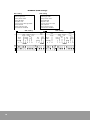
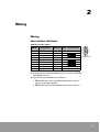
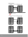
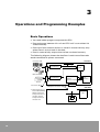
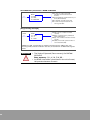
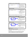
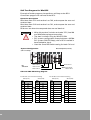
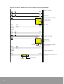
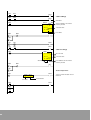
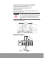
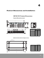
NX70/NX700 Serial Communications Unit (SCU)
User Manual
Important User Information
Solid state equipment has operational characteristics differing from those of
electromechanical equipment. Because of these differences, and also because of the
wide variety of uses for solid state equipment, all persons responsible for applying
this equipment must satisfy themselves that each intended application of this
equipment is acceptable.
In no event will Rockwell Samsung Automation be responsible or liable for indirect or
consequential damages resulting from the use or application of this equipment.
The examples and diagrams in this manual are included solely for illustrative
purposes. Because of the many variables and requirements associated with any
particular installation, Rockwell Samsung Automation cannot assume responsibility
or liability for actual use based on the examples and diagrams.
No patent liability is assumed by Rockwell Samsung Automation. with respect to use
of information, circuits, equipment, or software described in this manual.
Reproduction of the contents of this manual, in whole or in part, without written
permission of Rockwell Samsung Automation. is prohibited.
Throughout this manual we use notes to make you aware of safety considerations.
WARNING
IMPORTANT
ATTENTION
Identifies information about practices or circumstances which may
lead to serious personal injury or death, property damage, or
economic loss.
Identifies information that is critical for successful application and
understanding of the product.
Identifies information about practices or circumstances that can lead
to minor personal injury, property damage, economic loss, or
product malfunction. However, depending on circumstances, failure
to follow the directions accompanying this symbol may also lead to
serious consequences.
Contents
1. Specifications and Components ................................. 9
SCU Features .................................................................................................. 9
System Configuration................................................................................... 10
Specifications ................................................................................................ 11
Unit Diagram ................................................................................................. 12
Operation Status Display and Functions .................................................... 13
DIP Switch Settings ...................................................................................... 14
2. Wiring........................................................................ 17
Wiring ............................................................................................................ 17
3. Operations and Programming Examples................... 19
Basic Operations ........................................................................................... 19
Precautions for SCU Operation ................................................................... 20
Programming ................................................................................................ 22
NX70, NX700 PLC Installation Example...................................................... 33
PLC Programming Examples ....................................................................... 34
Troubleshooting............................................................................................ 47
4. Product Dimensions and Installation........................ 51
NX700 PLC Product Dimensions ................................................................. 51
NX70 PLC Product Dimensions ................................................................... 53
Power Unit Dimensions(mm) ...................................................................... 54
3
4
Safety Instructions
Please read this manual and the related documentation thoroughly
and familiarize yourself with product information, safety instructions
and other directions before installing, operating, performing
inspection and preventive maintenance. Make sure to follow the
directions correctly to ensure normal operation of the product and
your safety. Otherwise it may cause overheating and product
WARNING
• If this product is used in a situation that may cause
personal injury and/or significant product damage,
implement safe measures such as use of fault-safe
equipment.
• Do not use this product under any conditions exposed
to explosive gases. It may cause an explosion.
ATTENTION
• Make sure to use an external device when configuring
the protective circuit breakers for emergencies or
interlock circuits.
• Fasten the terminal screws tightly to ensure that the
cable connection is secure. Incorrect cable connection
may cause overheating and product malfunction.
• Operate and keep the product under the allowed
conditions directed in product specifications.
Otherwise it may cause overheating and product
malfunction.
• Do not disassemble or remodel the product.
Otherwise it may cause an electric shock or
malfunction.
• Do not touch the terminals when the power is on.
Otherwise it may cause an electric shock.
5
Installation Environment for SCU (Serial
Communication Unit)
ATTENTION
Do not install your analog conversion modules if any of
the following conditions are present:
• Ambient temperature outside the range of 0 to 55 °C
(32 to 131 °F).
• Direct sunlight.
• Humidity outside the range of 30% to 85% (Noncondensing).
• Chemicals that may affect electronic parts.
• Excessive or conductive dust, or salinity.
• High voltage, strong magnetic fields, or strong
electromagnetic influences.
• Direct impact and excessive vibration.
ATTENTION
Installing the SCU Module on the System
1. Connect a communication cable to the SCU module.
2. Turn on the power to the external device connected
to the SCU module.
3. Turn on the main PLC power.
ATTENTION
Removing the SCU Module from the System
1. Turn off the main PLC power.
2. Turn off the power to the external device connected
to the SCU module.
3. Remove the communication cable.
6
ATTENTION
Preventing SCU Module Malfunctions
• Be sure to power off the PLC system before installing
or removing an SCU module.
• Ensure that the SCU module is secured onto the
backplane before operating it.
• Be cautious of metal chips when wiring for the SCU
module. Metal chips and debris that fall into the
module can cause damage.
• Do not touch with your hand the connector on the
bottom of the module which is used to connect to the
backplane . Otherwise, it can cause connection fault
and static electrical discharges.
• Do not drop or impose impact to the SCU module. It
can cause damage because the housing is made of
injection-molded plastics.
ATTENTION
Preventing PLC System Malfunctions
• Use an isolation transformer and line filter on the
incoming power to the PLC when there is equipment
using or producing high current, high voltage, or
large magnetic fields in the vicinity.
• Use analog sensor that meets the rated specifications
for module connection. Otherwise,
it may cause operation errors.
• Separate the main PLC power line ground from all
other power grounds. Always use class 3 grounding.
• Do not exceed the current and power rating of the
external 24 VDC provided by the PLC power supply.
• Avoid system faults due to programming errors by
reading and fully understanding this system manual
and the PLC instruction set.
• Perform regular preventive maintenance on installed
systems, checking devices and wiring for potential
breakdowns and failures.
7
8
1
Specifications and Components
Exchange data with RS232C or RS485 communication devices, such as
barcode reader (RS232C) and network inverter (RS458). ASCII and HEX
(Binary) data transfer is enabled with ladder program. (SCU unit = the
existing features of SDU unit + 485 communication)
Read data with the advanced instruction, READ
NX70 PCL SCU Unit
(NX70-SCU)
NX700 PCL SCU Unit
(NX-SCU)
Write data with the advanced instruction,
SCU Features
1. Two channels are implemented on a single unit (RS232C, RS485
selectable).
2. Data input/output with simple sequence instructions.
Use PLC advanced instruction READ to read data from the SCU, and
WRITE to write data to the SCU. CPU unit and SCU will handle the
task with shared memory, so there is no need for writing
complicated programs.
3. SCU unit is equipped with RS-485 network feature, added to the
existing N-series SDU module features, expanding its scope of
usage.
4. RS232C or RS485 communication network is available.
Data input/output with RS232 devices:
Connect to and exchange data with devices like IDX display,
measurement instrument, barcode reader, and printer. Data input/
output with RS485 devices:
Connect through network to temperature controller, network
inverter, and network servo.
5. Unlimited mounting in PLC slots, 500 byte transmission capability.
9
6. Both ASCII and HEX (binary) can be used as transmission code.
7. End code can be configured freely with PLC ladder instructions.
NOTE
In addition to this Manual, please refer to System Manual and Programming
Manual for the PLC when using SCU.
System Configuration
Using RS232C Communication
Barcode Reader
ID Card
RS-232C Cable
Printer
Measurement
instrument
Using RS485C Communication
RS-485 communication
Inverter
network
RS-485 communication
Temperature
controller network
You can connect RS232C device/RS485 network device to each
RS232C/RS485 (CH1, CH2) channel.
NX series SCU can be mounted anywhere you want regardless of
whether the backplane is base or expansion. The number of SCU
mounting is not limited.
10
Specifications
General Specifications
Item
Temperature
Specifications
Operating 0 °C to +55 °C (32 °F to 131 °F)
Storage
-25 °C to +70 °C (-13 °F to 158 °F)
Operating 30 to 85% RH (Non-condensing)
Humidity
Storage
30 to 85% RH (Non-condensing)
Withstand voltage
500 V ac for 1 minute between I/O terminal (dc) and frame ground (power unit)
Insulation resistance
100 MΩ or more at 500 mega V dc between I/O terminal (dc) and frame ground
(power unit)
Vibration immunity
10 to 55Hz, 1 cycle/minute: double amplitude of 0.75 mm, 10 minutes on 3 axis
(X,Y, Z)
Shock immunity
Peak acceleration and duration 15g/11 ms, 3 times in each X, Y, Z direction
Noise immunity
1500 Vp-p with 50ns to 1µs pulse width (generated by noise simulator)
Ambience
No corrosive gas, no excessive dust
Occupied I/O points
32 points (16 points input, 16 points output)
Max. number of unit
Unlimited
Performance Specifications
Item
Specifications
Interface
RS232C/RS485 2 ports
Transmission speed
Configured with DSW1 and DSW2
1) Using RS232C: 300/600/1200/4800/9600/19200/38400bps
2) Using RS485: 4800/9600/19200/38400bps
Communication method
Half duplex
Synchronization method
Start-stop method
Transmission distance
Using RS232C: 15m (MAX), Using RS485: 1.2 Km
Transmission code
ASCII or HEX (Binary)
STOP bit 1bit/2bit
Transmission data
format
Parity (even/odd)
Data length 7bit/8bit
Data transmission order
From bit 0, by each character
Transmission unit
A message, to the end code (length adjustable)
Max. message length
MAX. 500 Byte/frame (including end and start codes)
Interface with
CPU unit
Shared memory type:
N-series: Read and write data with advanced instructions F150 (READ) and F151
(WRITE).
Read and write data with advanced instructions READ and WRITE.
I/O allocation
16 points input and 16 points output allocated.
End code setting
Select from three types of c cr d cr+LF e ETX or set arbitrary code from shared
memory.
Start code
Start code
Other special controls
End code cut transmission mode (control by sequence instruction),
Convenient for printing out.
Soft reset (control by sequence instruction)
NOTE
SCU module is configured as 32 points I/O module with 16 points input and 16 points output.
(For N-series, I/O is allocated by WinFPST S/W and registered as 16SX and 16SY.)
11
Unit Diagram
Front View
NX700 SCU (NX-SCU)
NX70 SCU (NX70-SCU)
Operation status display
Reset switch
Forced reset on
the SCU.
RS-232C/485
Interface (CH1)
RS-232C/485
Interface (CH1)
Inside View
NX700 SCU (NX-SCU)
ON
ON
ON
1 2 3 4 5 6 7 8 1 2 3 4 5 6 7 8 1 2 3 4 5 6 7 8
DSW1
DSW2
DSW3
Dip Switch (for CH1, CH2)
NOTE
12
Dip switch is located on the bottom of NX70 SCU (NX70-SCU).
Operation Status Display and Functions
SCU operation and communication status is displayed on the LED on
the top of the front panel.
SCU front display window
NX-SCU
NX70-SCU
NX700 SCU
(NX-SCU)
SCU
ALARM
SD2
RD2
ERR2
SCU
PWR
SD1
RD1
ERR1
PWR
SD1
RD1
ERR1
ALARM
SD2
RD2
ERR2
NX70 SCU
(NX70-SCU)
Implications
LED items
Power (PWR)
Function
● (On): Unit in operation
○ (Off): Power turned off
● (On): Operation error
Operation error (ALARM)
Turned on when watchdog timer identifies an
error. (Press the Reset switch to turn off.)
○ (Off): Normal operation
CH.1
CH.2
NOTE
Sending data monitor
(SD 1)
◎ (Flickering): Sending data
○ (Off): No sending data.
Receiving data
monitor (RD 1)
◎ (Flickering): Receiving data
○ (Off): No receiving data.
Communication error
(ERR 1)
● (On): Communication error
○ (Off): Normal communication
Sending data monitor
(SD 2)
◎ (Flickering): Sending data
○ (Off): No sending data.
Receiving data
monitor (RD 2)
◎ (Flickering): Receiving data
○ (Off): No receiving data.
Communication error
(ERR 2)
● (On): Communication error
○ (Off): Normal communication
•
Communication error LED (ERROR LED) turns on when parity or framing error
occurs.
Receiving: Parity, framing ERROR
Sending: No end code
•
Communication error LED turns off when normal frame is received or sent
(writing to shared memory).
13
DIP Switch Settings
CH1 Setting
DIP Switch is located inside the SCU.
CH1 setting
Start
code
Data
length
Parity Control
setting code
Stop
Parity
bit
Check
BaudRate
Data
length
Xpara
-meter
End
code
BaudRate
DSW3
NO
NO
DSW2
NO
DSW1
Start
Parity Control
code
setting
code
XStop
Parity
End
para
bit
Check
code
-meter
Bit location1)
DSW1
1
2
3
0
0
0
1
0
1
0
1
0
1
0
1
1
0
0
1
1
0
0
0
1
1
1
1
4
5
6
7
8
1
2
3
38400 Bps
Transmission speed
(BAUD RATE) (see below)
0
1
0
1
0
1
0
1
DSW2
0
0
1
1
0
1
0
1
Parity check (see below)
Invalid
Valid
Parity setting
Odd parity (ODD)
Even parity (EVEN)
STOP bit length
1 STOP Bit
2 STOP Bit
Not used
Used
End code (see below)
Set to shared memory (1 byte)
CR (0DH) code
CR (0DH), LF (0AH) code
ETX (03H) code
Start code (see below)
STX (02H) not used
STX (02H) used
X-Parameter
Not support
“0”stands for OFF. “1” stands for ON.
ATTENTION
14
7 BIT
8 BIT
(CTS, CD)
0
1
0
1
19200 Bps
9600 Bps
4800 Bps
2400 Bps
1200 Bps
600 Bps
300 Bps
Data length
Control signal (see below)
0
1
1)
Function
4
• When using RS485, the available baud rates are
38,400/19,200/9,600/4,800bps.
• When parity check is set to Invalid, the parity settings
are not applied.
• For control signal, the CTS and CD settings can be
selected, but set it to Not Applicable when using
[3-wire method without flow control]. (using RS232C
communication)
• Start and end codes determine the start and end of a
communication frame.
CH2 Setting
CH2 Setting
Start
code
Data
length
Parity Control
setting code
Stop
Parity
bit
Check
BaudRate
Data
length
Xpara
-meter
End
code
DSW3
NO
NO
DSW2
NO
DSW1
BaudRate
Start
Parity Control
code
setting code
XStop
Parity
End
para
bit
Check
code
-meter
Bit location1)
DSW2
1
2
3
0
0
0
1
0
1
0
1
0
1
0
1
1
0
0
1
1
0
0
0
1
1
1
1
4
5
6
7
8
1
2
3
38400 Bps
Transmission speed
(BAUD RATE) (see below)
0
1
0
1
0
1
0
1
DSW3
7 BIT
8 BIT
Parity check (see below)
Invalid
Valid
Parity setting
Odd parity (ODD)
Even parity (EVEN)
Stop bit length
1 Stop Bit
2 Stop Bits
(CTS, CD)
0
1
0
1
0
0
1
1
0
1
0
1
19200 Bps
9600 Bps
4800 Bps
2400 Bps
1200 Bps
600 Bps
300 Bps
Data length
Control signal (see below)
0
1
1)
Function
4
Not used
Used
End code (see below)
Set to shared memory (1 byte)
CR (0DH) code
CR (0DH), LF (0AH) code
ETX (03H) code
Start code (see below)
STX (02h) not used
STX (02h) used
X-Parameter
Not support
“0”stands for OFF. “1” stands for ON.
ATTENTION
• When using RS485, the available baud rates are
38,400/19,200/9,600/4,800bps.
• When parity check is set to Invalid, the parity settings
are not applied.
• For control signal, the CTS and CD settings can be
selected, but set it to Not Applicable when using
[3-wire method without flow control]. (using RS232C
communication)
• Start and end codes determine the start and end of a
communication frame.
15
EXAMPLE (DSW Settings)
CH1 setting
CH2 setting
Transmission speed: 9600 bps
Data length: 8 bit
Parity Check : Valid
Parity Bit: Odd
Stop Bit: 1 Bit
Control signal: Not used
End code: CR
Start code: Not used
X-Parameter: Disabled
Transmission speed: 9600 bps
Data length: 8 bit
Parity Check: Valid
Parity Bit: Odd
Stop Bit: 1 Bit
Control signal: Not applicable
End code: CR
Start code: Not used
X-Parameter: Disabled
CH1 Setting
CH2 Setting
Start
code
Data
length
End
code
16
BaudRate
Start
Parity Control
code
setting code
XStop
End
Parity
para
bit
code
Check
-meter
DSW2
NO
NO
DSW1
Xpara
-meter
Data
length
DSW3
NO
BaudRate
Parity Control
setting code
Stop
Parity
bit
Check
2
Wiring
Wiring
RS232C/RS485 INTERFACE
SCU Connection Signal
PIN NO
Signal Name
Mnemonic
FG
2
SEND DATA
SD
3
RECEIVE DATA
RD
6789
FRAME GROUND
External device
12345
1
Direction
SCU
Connector (9P)
4
5
SIGNAL GROUND
GND
6
485 TRANSIVER-
485-
7
485 TRANSIVER+
485+
POWER
+5V
8
9
●
External device referred above means a variety of RS232
and RS485 devices.
●
Typical wiring methods are as follows:
1. RS232 Wiring: 3-wire method without flow control
(common wiring method)
2. RS485 Wiring: End termination resistance is built-in.
17
RS232 Wiring Diagram
3-wire method without flow control (RS232 device - 9 pin)
SCU (9P)
PIN NO
RS-232 device (9P)
Mnemonic
1
PIN NO
Mnemonic
1
FG
2
SD
2
RD
3
RD
3
SD
4
DTR
4
5
SG
5
SG
6
RS485-
6
DSR
7
RS485+
7
RTS
8
8
CTS
9
9
RI
ATTENTION
Turn off the DSW1 No. 8 or DSW3 No.4 which are the
control codes.
3-wire method without flow control (RS232 device-25 pin)
SCU (9P)
PIN NO
Mnemonic
1
RS-232 device (25P)
PIN NO
Mnemonic
1
FG
2
SD
2
SD
3
RD
3
RD
4
RTS
4
5
SG
5
CTS
6
RS485-
6
DSR
7
RS485+
7
SG
8
8
CD
9
20
DTR
RS485 Wiring Diagram
SCU (9P)
PIN NO
RS-485 device
Mnemonic
Mnemonic
6
485+
485+
7
485-
485-
1
2
3
4
5
8
9
18
3
Operations and Programming Examples
Basic Operations
●
You need ladder program to operate the SCU.
●
Data exchanges between this unit and CPU unit is transmitted via
shared memory.
●
Data input from external devices is stored in shared memory only
when there is an end code in the data.
●
Data is automatically output when written to shared memory.
The following diagram shows the data flow in each case of barcode
reader connected or printer connected.
Connector (9P)
SCU Unit
C
H
1
RS232C (RS485)
Drive Receiver
9788940200278
c
CPU
h
d
Barcode Reader
C
H
2
RS232C (RS485)
Drive Receiver
Shared
memory and I/O
Printer
Connector (9P)
Data
e
Data
Memory
Backplane connector (50p)
CPU Unit
*1 Shared memory of
SCU enables READ/
WRITE at both the
CPU (processor) of
the SCU and the
CPU(processor) of
the CPU unit.
19
f
g
Data
Memory
CPU
SCU (unit processing)
Input to the SCU
from external
devices
Barcode c
Reader
CPU
d
Memory
e
Shared f
memory
SCU (unit processing)
Output from
inside the SCU
Printer
ATTENTION
h
CPU
d
Memory
e
CPU unit (ladder program)
g
CPU
Memory
CPU unit (ladder program)
Shared f
memory
CPU
g
Memory
Products like ID-X, where I/O (sending/receiving)
passes through only one channel, can be operated as
half duplex.
The SCU performs communications regardless of
PROG/RUN mode, but data transmission is available
only in RUN mode.
Precautions for SCU Operation
For ASCll communication of Rs232C/RS485
●
Errors of transmission processing are reflected at contacts
(NX series: X4 to XD, NX plus series: R0.4 to R0.13) so resending
with ladder program is recommended. (See below)
If an error occurs while the frame is receiving, the frame will be
cleared and error LED turns on. But if the next frame is a normal
frame, the error LED turns off and the frame is processed as the
received frame.
●
When the start code is effective, the frame will start at the last
receiving start code and end at the end code.
[Ex]
STX
STX
ETX
STX: Start code
ETX: End code
Start code is effective: 1 frame
Start code is not effective
1. When the end code is not received due to communication
trouble, the SCU stands by until the end code is received.
2. You can prevent a prolonged stand-by as follows:
Request resending to the external RS232C (RS485) device.
If resending is not available at the other RS232C (RS485) device,
perform time-up process with ladder program and request
resending to the external device.
20
3. The SCU buffer status when resending from the external RS232C
(RS485) device is as follows:
Start code is
not effective
STX
STX
ETX
Resent frame
Previous frame
To shared memory of the received frame
Start code is
effective
STX
STX
Previous frame
ETX
Resent frame
To shared memory of the
received frame
●
Software reset is available when resetting the SCU in emergency.
1. Turn Y1D (R1.13) on with ladder program to reset. (Software
reset)
2. It takes approx. 1msec from software reset request to complete
initialization.
3. XE (R0.14) turns on when initialization completes.
●
Ensure the following when set end code with shared memory.(The
end code is read from shared memory at every sending and
receiving process.)
1. Sending: Set the end code before sending request.
2. Receiving: Set the end code before the external RS232C (RS485)
device starts transmission.
●
When Y1E (R1.14) → (CH1), Y1F (R1.15) → (CH2) is turned on, the end
code transmission can be disabled. (Convenient for output to the
printer.)
Make sure to turn on Y1E (R1.14) and Y1F (R1.15) before sending
request.
21
Programming
Send and receive data with CPU unit ladder program for data READ /
WRITE with shared memory in the SCU. Two advanced instructions are
used for this: READ (F150) and WRT (F151).
In addition, handshake for data READ/WRITE will be determined by
contact on/off (two points for each X and Y).
Data read from
special (high-function)
unit (F150)
Shared memory
Data write to
special (high-function)
unit (F151)
High-function unit
Register
(Word operand)
NX Series
NX plus series
WX, WY.....
DT (data)
FL (file)
Ld (link)
R.....
M (data)
W (file)
L (link)
CPU unit
Special (highfunction) Unit:
Special units
that include
process and
shared memory
inside the unit.
(Ex. SCU,
Analog, Location
Spotting units)
Program Configuration
●
A program consists of handshake with shared memory and
advanced instructions.
See "Timing for Sending and Receiving" on page 25 for detailed
information on handshake timing.
See "Advanced Instructions" on page 27 for detailed information on
PLC advanced instructions.
See "Shared Memory Allocation Table" on page 29 for detailed
information on shared memory.
See "I/O Allocation Table" on page 31 for detailed information on I/O
allocation.
22
Using READ in WinFPST
(Receiving from external RS232C (RS485) device)
When SCU is installed in the first slot of PLC system and external
RS232C (RS485) is connected to CH1.
X1
X1
Y11
Y11
R100
R100
R100
R101
Condition for READ
X1: For CH1 receiving
Condition for READ
completion
X1 turns on when normal data is input
to the RS232C (RS485) device
connected to CH1.
READ
Y11: For CH1 receiving
When reading received data from
shared memory, turn on Y11.
Turn on Y11 when X1 is turned off.
F150 (READ)
(Data READ from
high function unit.)
R101
Y11
READ completion signal
(Output to the SCU unit)
Y11
Using WRITE in WinFPST
(Transmitting to external RS232C (RS485) device)
When SCU is installed in the first slot of PLC system and external
RS232C (RS485) is connected to CH1.
XO
Y1O
XO
Y1O
R103
R103
Condition for
WRITE
R104
Condition for
WRITE
completion
F151 (WRT)
(Data WRITE to
high-function unit )
WRITE
R103
Y1O
23
R104
Y1O
WRITE completion
signal
(Write to the SCU unit)
X0: For CH1 sending
When the SCU received correct data,
X0 turns on.
Y10: For CH1 sending
When writing sending data to shared
memory,
turn on Y10.
Turn off Y10 when X0 is turned on.
Using READ in WinGPC
(Receiving from external RS232C (RS485) device)
When SCU is installed in the first slot of PLC system and external
RS232C (RS485) is connected to CH1.
R0.1
R0.1
R1.1
R1.1
R100
R100
R100
R101
Condition for READ
R0.1: For CH1 receiving
Condition for READ
completion
R0.1 turns on when normal data is input
to the RS232C (RS485) device
connected to CH1.
READ
R1.1: For CH1 receiving
When reading received data from
shared memory, turn on R1.1.
Turn on R1.1 when R0.1 is turned off.
READ
(Data READ from
high function unit.)
R101
R1.1
READ completion signal
(Output to the SCU unit)
R1.1
Using WRITE in WinGPC
(Transmitting to external RS232C (RS485) device)
When SCU is installed in the first slot of PLC system and external
RS232C (RS485) is connected to CH1.
R0.0
R1.0
R0.0
R1.0
R103
R103
Condition for
WRITE
R104
Condition for
WRITE
completion
WRITE
(Data WRITE to
high-function unit )
WRITE
R103
R1.0
24
R104
R1.0
WRITE completion
signal
(Write to the SCU unit)
R0.0: For CH1 sending
When the SCU received correct data,
R0.0 turns on.
R1.0: For CH1 sending
When writing sending data to shared
memory,
turn on R1.0.
Turn off R1.0 when R0.0 is turned on.
Timing for Sending and Receiving
Regardless of the slot location where the SCU is installed, sending and
receiving is available. It is controlled by contacts on/off status. Per each
CH, 2 points for sending and 2 points for receiving.
(Ex) When installed in slot 0
CH1
For sending
CH2
For sending
X0 (R0.0)
Y10 (R1.0)
X2 (R0.2)
Y12 (R1.2)
For receiving
For receiving
X1 (R0.1)
Y11 (R1.1)
X3 (R0.3)
Y13 (R1.3)
Timing Chart for CH1 using.
Sending
Data WRITE from PLC CPU to SCU shared memory, and Y10 (R1.0)
on/off setting should be controlled by ladder program.
Sending
SCU
starts
XO (R0.0)
Read from SCU
shared memory to SCU CPU, and
send it to the external device
BUFFER CLEAR
Data
Y10 (R1.0)
Perform
with ladder
program
Data
Write data from PLC CPU
to SCU shared memory.
X0 turns on when the transmission completes with the
end code from the SCU to the external device.
Receiving
Data READ with PLC CPU from SCU shared memory, and Y11 (R1.1)
on/off setting should be performed by ladder program.
Receiving
SCU
starts
X1 (R0.1)
Save data from
the external device
to shared memory.
Data
BUFFER CLEAR
Y11 (R1.1)
Perform
with ladder
program
Data
Read SCU shared memory
data with PLC CPU unit
25
Timing chart for CH2 using
Sending
Data WRITE from PLC CPU to SCU shared memory, and Y12 (R1.2)
on/off setting should be performed by ladder program.
Sending
SCU
starts
X2 (R0.2)
Read from SCU
shared memory to SCU CPU, and
send it to the external device
BUFFER CLEAR
Data
Y12 (R1.2)
Perform
with ladder
program
Data
Write data from PLC CPU
to SCU shared memory.
Receiving
Data READ with PLC CPU from SCU shared memory, and Y13 (R1.3)
on/off setting should be performed by ladder program.
Receiving
SCU
starts
X3 (R0.3)
Save data from
the external device
to shared memory.
Data
BUFFER CLEAR
Y13 (R1.3)
Perform
with ladder
program
Data
Read SCU shared memory
data with PLC CPU unit
26
Advanced Instructions
Shared Memory instruction - READ in WinFPST
[ F150 READ, S1, S2, n, D ]
S1: Installation slot number of SCU unit.
S2: Starting address of shared memory
where source data is stored.
n: The number of words of source data
to read.
D: Starting address of PLC CPU where
to store the read data.
[Programming Example]
RO
[ F150 READ, K3, K251, K2, DT15 ]
K3: SCU slot (slot 0)
K251: SCU shared memory address
(Address 251)
K2: The number of words of data to
read (2 words)
DT15: Starting word operand of PLC
CPU where to store the read
data (DT15)
When R0 is on, the SCU shared memory address 251 (CH1 receiving buffer) reads
two words of data and send it to NX700 PLC CPU data registers, DT15 and DT16.
IMPORTANT
27
• The operands (called device, data, or register in other
company’s products) can be divided into bit
operand that processes bit information and word
operand that processes word information.
Word operand: WX, WY, WR, WL, Ld, DT, FL, EV, SV,
IX, IY.. I0 to ID
Contact operand: X, Y, R, L, T, C... .
• F150 (READ) instruction processes word, so 10byte
data is processes as 5 words.
Shared Memory instruction - READ in WinGPC
READ
To = RR1
Sz = NR3
Fr = NN5:NR6
NN5 : Slot no. of SCU mounted.
(Number, and first I/0 slot start
from 0)
NR6 : Start address of shared memory of
SCU (Word address)
NR3 : Number of words to be read
RR1 : Start word operand of PLC for
storing read data
[Programming Example]
M0.0
READ
To = 2W0
Sz = 2
Fr = 0:251
NN5(0) : Slot no. of SCU mounted.
(Slot 0)
NR6(251) : shared memory address of
SCU (address 251)
NR3(2) : the number of words to read (2
words)
RR1(W0) : First word operand of PLC to
store read data (W0)
If M0.0 turns ON , 2 words data is read from shared memory address 251 (CH1
receiving buffer) of SCU installed in slot no.0, and send them to W0 of data register
of PLC.
IMPORTANT
28
• The kinds of Operand (Data memory) for NX700/
NX70 PLC
Data memory : R, L, K, M, F, W, SR ..
• As READ instruction is executed in the unit of word,
10 byte data become 5 words
Shared Memory instruction - WRITE in WinFPST
[ F151 WRT, S1, S2, n, D ]
S1: Installation slot number of SCU
unit
S2: Starting address of the CPU where
the input data is stored.
n: The number of words of source
data to write to the destination.
D: Starting address of SCU shared
memory where the data will be
stored.
[Programming Example]
RO
[ F151 WRT, K0, DT100, K10, K1 ]
K0: SCU slot (slot 0)
DT100: Starting address of the PLC
CPU where the input data is
stored. (DT100)
K10: The number of words of source
data to write to the destination.
(2 words)
K1: Starting address of SCU shared
memory where the data will be
stored. (Address 1)
When R0 is on, 10 words from NX700 PLC data register DT100 (DT100 to DT109) will
be sent to the SCU shared memory address 1 (CH1 sending buffer).
Shared Memory instruction - WRITE in WinGPC
WRITE
To = NN1 : NR2
Sz = NR3
Fr = NN5
NN1 : Slot no. of SCU mounted.
(Number, and first I/0 slot start
from 0)
NR2 :First address to write on the shared
memory of SCU. (number/ register)
NR3 : Number of words to be written
NR5 : First address of data to writes
(number/ register)
[Programming Example]
M0.1
WRITE
To = 0 : 1
Sz = 2
Fr = W0
NN1(0) : Slot no. of SCU mounted.
( Slot no. 0)
NR2(1) : First address to write on the
shared memory of SCU. (address 1)
NR3(2) : Number of words to be written
(2 words)
NN5(W0) : Start word operand of write
data (W0)
When M0.1 becomes ON, 2 words from data register W0 of NX70/NX700 PLC is
transmitted into shared memory address 1 (CH1 transmission buffer) of SCU
installed in slot no. 0.
Shared Memory Allocation Table
SCU has built-in shared memory that is READ/WRITE accessible from
PLC CPU unit.
Inside the shared memory, the sending and receiving areas are
allocated. Therefore, PLC CPU unit and RS232C external devices
performs data READ/WRITE through SCU shared memory.
29
Data transmission handshake is processed at PLC contacts on/off
(two points for each input and output).
Shared memory allocation
Address
1
250
251
500
501
750
751
1000
NOTE
30
250 words
(500 characters)
CH1 sending buffer → RS-232C (RS485) device
250 words
(500 characters)
CH1 receiving buffer ← RS-232C (RS485) device
250 words
(500 characters)
CH2 sending buffer → RS-232C (RS485) device
250 words
(500 characters)
CH2 receiving buffer ← RS-232C (485) device
1001
CH1 end code
configuration area
1002
CH2 end code
configuration area
1003
CH1 sending data length
1004
CH1 receiving data length
1005
CH2 sending data length
1006
CH2 receiving data length
Effective only when DIP SWITCH [shared
memory] is set, and set to lower bytes.
Effective only when the CH1
communication is set to HEX (BIN).
Effective only when the CH2
communication is set to HEX (BIN).
Sending buffer area: Data for sending is stored.
Receiving buffer area: Received data is stored.
I/O Allocation Table
The X, Y contact number for I/O is determined by the installation
location of the SCU and the number of points of other I/O units.
The I/O numbers shown below are applied when the SCU is installed
in slot 0 of base backplane.
For I/O of SCU, 16 points from X0 to XF will be allocated for input and
16 points from Y10 to Y1F will be allocated for output.
The meaning of each I/O contact is shown in the table below and the
handshake processing will be based on this status.
Input signal
N-plus
series
X0
R0.0
For CH1 sending
X0 (R0.0) turns on when the SCU receives sending data. *1
X1
R0.1
For CH1 receiving
X1 (R0.1) turns on when normal data is input from devices
connected to CH1. *1
X2
R0.2
For CH2 sending
X2 (R0.2) turns on when the SCU receives sending data. *1
X3
R0.3
For CH2 receiving
X3 (R0.3) turns on when normal data is input from devices
connected to CH2. *1
X4
R0.4
For CH1 receiving data
X4 (R0.4) turns on only when framing error occurs in received data.
X5
R0.5
For CH1 receiving data
X5 (R0.5) turns on only when parity error occurs in received data.
X6
R0.6
For CH1 receiving data
X6 (R0.6) turns on when the received data buffer is full.
X7
R0.7
For CH1 receiving data
X7 (R0.7) turns on when message length error occurs in received
data.
X8
R0.8
For CH1 sending data
X8 (R0.8) turns on when message length error occurs in sending
data.
X9
R0.9
For CH2 receiving data
X9 (R0.9) turns on only when framing error occurs in received data.
XA
R0.10
For CH2 receiving data
XA (R0.10) turns on only when parity error occurs in received data.
XB
R0.11
For CH2 receiving data
XB (R0.11) turns on when the received data buffer is full.
XC
R0.12
For CH2 receiving data
XC (R0.12) turns on when message length error occurs in received
data.
XD
R0.13
For CH2 sending data
XD (R0.13) turns on when message length error occurs in sending
data.
XE
R0.14
For SCU operation ready indication
XE (R0.14) turns on when SCU initialization completes.
XF
R0.15
Unused
NOTE
31
Event
N-series
See "Timing for Sending and Receiving" on page 25 for detailed information.
Input signal
N-plus
series
Y10
R1.0
For CH1 sending
Y10 (R1.0) turns on when sending data is written to shared memory.
Turn off Y10 (R1.0) when X0 (R0.0) is turned on.
Y11
R1.1
For CH1 receiving
Y11 (R1.1) turns on when sending data is read from shared memory.
Turn off Y11 (R1.1) when X1 (R0.1) is turned off.
Y12
R1.2
For CH2 sending
Y12 (R1.2) turns on when sending data is written to shared memory.
Turn off Y12 (R1.2) when X2 (R0.2) is turned on.
Y13
R1.3
For CH2 receiving
Y13 (R1.3) turns on when sending data is read from shared memory.
Turn off Y13 (R1.3) when X3 (R0.3) is turned off.
Y14
R1.4
Unused
Y15
R1.5
Unused
Y16
R1.6
Unused
Y17
R1.7
Unused
Y18
R1.8
Data format setting of CH1
On for ASCII and Off for HEX (Binary) format
Y19
R1.9
Data format setting of CH2
On for ASCII and Off for HEX (Binary) format
Y1A
R1.10
Unused
Y1B
R1.11
Unused
Y1C
R1.12
Unused
Y1D
R1.13
For software reset
SCU is initialized when Y1D (R1.13) is turned on.
Approx. 1msec after initialization completes, XE (R0.14) turns on.
Turn off Y1D (R1.13) immediately after XE (R0.14) turns on.
Y1E
R1.14
CH1
If Y1E (R1.14) is turned on before data send request turn in Y10
(R1.0), end code will not be transmitted.
Y1F
R1.15
CH2
If Y1F (R1.15) is turned on before data send request turn in Y12
(R1.2), end code will not be transmitted.
NOTE
32
Event
N-series
Data error warning signals (X4 to XD, R0.4 to R0.13) turn off when SCU reset
switch is pressed or normal data is received.
NX70, NX700 PLC Installation Example
NX700 PLC system configuration is illustrated below.
In this case, the SCU is installed in slot no.4 and I/O units are installed
in slot no. 0 to 3.
Base backplane (5 slots)
0
1
64 points input
(X0 to X3F, R0.0 to R3.15)
32 points input
(X40 to X5F, R4.0 to R5.15)
32 points output
(Y60 to Y7F, R6.0 to R7.15)
2
3
4
SCU unit
16 points input: X90 to X9F, R9.0 to R9.15
16 points output: Y100 to Y10F, R10.0 to R10.15
16 points output
(Y80 to Y8F, R8.0 to R8.15)
IMPORTANT
33
• There is no limit on the location and number of SCU
installed, and SCU can be installed regardless
whether the backplane is base or expansion.
• When allocating I/O map with WinFPST, SCU is
allocated as "16SX and 16SY".
• When allocating I/O map with WinGPC, SCU is
allocated as "Both".
PLC Programming Examples
Self-Test Program for WinFPST
Example of ladder program that performs self-loop at the SCU.
Convenient program for self-test of the SCU.
Operation description
Send data from CH1 and receive it at CH2, and compare the sent and
received data.
Send data from CH2 and receive it at CH1, and compare the sent and
received data.
Y50 turns on when the compared data are not identical.
IMPORTANT
• Data WRITE method: WinFPST S/W → on-line → DT0,
DT1 and DT5, DT6 at register monitoring.
Then, verify data at each of DT10, DT11 and DT15,
DT16. (See WinFPST S/W help for detailed
information. )
• DIP SWITCH (DSW) setting must be identical at CH1
and CH2, and the setting is arbitrary.
• PLC system configuration example shows a NX700
PLC system (NX-CPU700, NX-CPU750A, B, C, or D),
with a SCU installed in base backplane slot 3.
• Use 9-pin cable when
RS232C communication checking at CH1 and CH2
of the SCU, and use 2-pin connection when
RS485 communication checking. (See the wiring
System Configuration
(NX-CPU700, NX-CPU750A, B, C, D)
NX-Y16RV
RY OUT
NX-SCU
SCU
34
NX-X16D
DC IN
Y10 ~ Y1F
X20 ~ X2F
NX-Y16RV
RY OUT
X0 ~ XF
NX-X16D
DC IN
I/O
allocation
CPU
NX-CPU750B
Base backplane (5 slots)
Y50 ~ Y5F
SCU X30 ~ X3F
Y40 ~ Y4F
CH1 and CH2 PIN wiring diagram
For RS-232C communication checking
SCU (CH1)
SCU (CH2)
SCU (CH1)
SCU (CH2)
PIN
NO
Mnemonic
PIN
NO
Mnemonic
PIN
NO
1
FG
1
FG
1
1
2
SD
2
SD
2
2
3
RD
3
RD
3
3
4
4
5
5
4
5
35
For RS-485 communication checking
4
SG
5
SG
Mnemonic
PIN
NO
Mnemonic
6
6
6
485-
6
485-
7
7
7
485+
7
485+
8
8
8
8
9
9
9
9
Sequence Program - ASCII format self-test ladder program (for WinFPST)
R9010
Y48
Set CH1 to ASCII mode
R9010
Y49
[ F0
[ F0
[ F0
[ F0
MV
MV
MV
MV
Set CH2 to ASCII mode
H3131, DT0 ]
HD, DT1 ]
H3232, DT10 ]
HD, DT11 ]
R9014
DF
NSTP 1
NSTP 3
<CH1 sending>
SSTP 1
X30
Y40
X30
Y40
R0
R1
(F151)WR
R0
K
DT
K
K
R0
Slot NO.3
3
0
2
1
R1
Sending from CPU DT0
2 words of data
Y40
Y40
is stored to SCU shared
memory address
R1
NSTP 2
SSTP 2
<CH2 sending>
X33
Y43
R2
X33
Y43
R3
R2
(F150 READ)
K 3
K 751
K 2
K 5
R2
R3
SCU shared memory
From address 751
2 words of data
Y43
is stored to PLC CPU
DT5 and DT6.
Y43
R3
(F60)CMP
DT 6
R900B
R8
R3
NSTP 1
36
Data comparison
Sent data (end code
comparison)
Received data (end code
comparison)
DT 1
R3
Slot NO.3
Turns on when the data are not
identical.
<CH2 sending>
Slot NO.3
From PLC CPU DT10,
2 words of data
Is stored to SCU shared
memory address 501
<CH1 receiving>
Slot NO.3
From SCU shared memory
address 251,
2 words of data
is stored to PLC CPU
DT15 and DT16.
Data comparison
Sent data (end code
comparison)
Received data
37
Sequence program - HEX format self-test ladder program (for
WinFPST)
<CH1 sending>
From slot NO.3 DT0, 1 word of
data is stored to shared
memory address 1.
From slot NO.3 DT100, 2 words
of data is stored to SCU shared
memory address 1003
transmission length setting.
<CH2 sending>
Slot NO.3
From SCU shared memory
address 751,
1 word of data is stored
to PLC CPU DT5.
Data comparison
Sent data
Received data
Turns on when the data are not
identical.
38
<CH2 sending>
From slot NO.3 DT0, 1 word of
data is stored to SCU shared
memory address 501.
From slot NO.3 DT102, 2 words
of data is stored to SCU shared
memory address 1005.
(transmission length setting)
<CH1 receiving>
Slot NO.3
From SCU shared memory
address 251,
1 word of data is stored
to PLC CPU DT15.
Data comparison
Sent data
Received data
39
Self-Test Program for WinGPC
Example of ladder program that performs self-loop at the SCU.
Convenient program for self-test of the SCU.
Operation description
Send data from CH1 and receive it at CH2, and compare the sent and
received data.
Send data from CH2 and receive it at CH1, and compare the sent and
received data.
R5.0 turns on when the compared data are not identical.
IMPORTANT
• Write 2-byte data( includes end code "CR") into W0
and W10 before program execution.
• The data is written using by WinGPC S/W.
• PLC system configuration example shows a NX700
PLC system (NX-CPU700p), with a SCU installed in
base backplane slot 3.
• Used the same DIP Switch setting for both Ch1 and
System Configuration
(NX-CPU700p)
Base backplane (5 slots)
NX-Y16RV
RY OUT
NX-SCU
SCU
NX-X16D
DC IN
NX-Y16RV
RY OUT
NX-X16D
DC IN
I/O
allocation
CPU
NX-CPU750B
R5.0 to R5.15
R0.0 to R0.15
R1.0 to R1.15
SCU R3.0 to R3.15
R4.0 to R4.15
R2.0 to R2.15
CH1 and CH2 PIN wiring diagram
For RS-232C communication checking
SCU (CH1)
PIN
NO
PIN
NO
1
FG
2
SD
3
RD
5
40
SCU (CH2)
Mnemonic
4
SCU (CH1)
SCU (CH2)
Mnemonic
PIN
NO
1
FG
1
1
2
SD
2
2
3
RD
3
3
4
4
4
SG
For RS-485 communication checking
5
SG
Mnemonic
5
PIN
NO
Mnemonic
5
6
6
6
485-
6
485-
7
7
7
485+
7
485+
8
8
8
8
9
9
9
9
Sequence Program - ASCII format self-test ladder program (for WinGPC)
<CH1 sending>
R3.0
M0.0
R4.0
( )
R3.0
R4.0
M0.1
( )
M0.0
WRITE
Slot NO.3
To = 03 : 1
save to address 1 of shared
memory of SCU
Sz = 1
1 word of data
Fr =W0
from W0
M0.0
M0.1
R4.0
( )
R4.0
R3.3
R4.3
R3.3
R4.3
M0.2
( )
M0.3
( )
M0.0
<CH2 receiving>
READ
To = W5
Save to W5
Sz = 1
1 word of data
Fr =03:751
from address 751 of shared
memory of SCU
Slot NO.3
M0.2
M0.3
R4.3
( )
R4.3
<Data comparison>
M0.3
M0.8
( )
W0 < > W5
sent data
41
received data
Turns on when the data are not
identical.
R3.2
R4.2
M0.4
( )
R3.2
R4.2
M0.5
( )
M0.4
WRITE
<CH2 sending>
Slot NO.3
To = 03 : 501
save to address 1 of shared
memory of SCU
Sz = 1
1 word of data
Fr =W10
from W10
M0.4
M0.5
R4.2
( )
R4.2
R3.1
R4.1
R3.1
R4.1
M0.6
( )
M0.7
( )
M0.6
<CH1 receiving>
READ
To = W15
Save to W15
Sz = 1
1 word of data
Fr =03:751
from address 751 of shared
memory of SCU
Slot NO.3
M0.6
M0.7
R4.1
( )
R4.1
<Data comparison>
M0.7
M0.9
W10 < > W15
sent data
M0.8
M0.9
R5.0
42
( )
received data
M5.0
( )
Turns on when the data are not
identical.
Example of Using a Barcode Reader for WinFPST
Connect a barcode reader to SCU CH1.
(ex. Barcode reader: (Japan) TOKEN THLS-6300)
Read barcode information and store it to PLC.
Operation description
Read the information at the barcode reader connected to CH1 and
store it to from PLC DT100.
IMPORTANT
• The DIP switches (DSW1 and DSW2) are set to 9600
bps, 8 bit, no parity, 1 stop bit, and end code is CR.
• SCU is installed in base backplane slot 0 of a NX700
PLC system (NX-CPU700, NX-CPU750A, B, C, D).
• Connect SCU CH1 and barcode reader with 9-pin
cable.
SCU DIP switch (CH1) settings
CH1 Setting
Baud
rate
Start
Data Parity Control
code
length setting code
End
Parity Stop
bit
code
check
X-parameter
DSW2
DSW1
ON
ON
NX700 System Configuration
(NX-CPU700, NX-CPU750A, B, C, D)
SCU
X0 to XF
Y10 to Y1F
Y20 to Y2F
Y30 to Y3F
Barcode reader
(THLS-6300)
43
NX-X16D
DC IN
9-pin cable
NX-X16D
DC IN
NX-Y16RV
RY OUT
NX-Y16RV
RY OUT
NX-SCU
SCU
CPU
NX-CPU750B
Sequence Program – Ladder program example for using a barcode
reader (for WinFPST)
Set CH1 to ASCII mode
setting
<CH1 receiving>
Slot NO.0
From SCU shared memory
address 251,
20 words of data is stored to
PLC CPU
from DT100
44
Example of Using a Barcode Reader for WinGPC
Connect a barcode reader to SCU CH1.
(ex. Barcode reader: (Japan) TOKEN THLS-6300)
Read barcode information and store it to PLC.
Operation description
Read the information at the barcode reader connected to CH1 and
store it to from PLC DT100.
IMPORTANT
• The DIP switches (DSW1 and DSW2) are set to 9600
bps, 8 bit, no parity, 1 stop bit, and end code is CR.
• SCU is installed in base backplane slot 0 of a NX700
PLC system (NX-CPU700p).
• Connect SCU CH1 and barcode reader with 9-pin
cable.
SCU DIP switch (CH1) settings
CH1 Setting
Baud
rate
Start
Data Parity Control
code
length setting code
End
Parity Stop
bit
code
check
X-parameter
DSW2
DSW1
ON
ON
NX700 System Configuration
(NX-CPU700p)
SCU
R0.0 to R0.15
R1.0 to R1.15
R2.0 to R2.15
R3.0 to R3.15
Barcode reader
(THLS-6300)
45
NX-X16D
DC IN
9-pin cable
NX-X16D
DC IN
NX-Y16RV
RY OUT
NX-Y16RV
RY OUT
NX-SCU
SCU
CPU
NX-CPU750B
Sequence Program – Ladder program example for using a barcode
reader (for WinGPC)
R0.1
R1.1
M0.0
0
<CH1 receiving>
( )
R0.1
R1.1
M0.1
3
( )
M0.0
READ
6
To = W100
Save to W100
continually
20 words of data
Sz = 20
Fr = 0 : 251
from address 251 of
shared memory of
the SCU
Slot No. 0
M0.0
16
R1.1
46
M0.1
R1.1
( )
Troubleshooting
47
48
49
R0.4 (R0.9)
R0.5 (R0.10)
R0.6 (R0.11)
R0.7 (R0.12)
R0.8 (R0.13)
The SCU is mounted in slot 0, and the contact number in ( ) is
the contact number of CH2 error indication.
50
4
Product Dimensions and Installation
NX700 PLC Product Dimensions
System Dimensions (mm)
A
B
NX-Y16T
TR OUT
NX-Y16T
TR OUT
NX-Y16T
TR OUT
NX-Y16T
TR OUT
NX-Y32T
TR OUT
NX-X32D
DC IN
NX-X64D
DC IN
NX-X64D
DC IN
CPU
NX-CPU750B
115.5
118.5
unit (mm)
Dimensions
Slot Types
111.0
A
B
3-slot type
205.0
183.8
5-slot type
276.0
254.2
8-slot type
381.0
359.8
10-slot type
452.0
430.2
12-slot type
522.0
500.6
Motherboard Installation Diagram (mm)
¥ı
5.0 * 4
27.5
81.0
L
7.0
22.5
unit (mm)
SLOT
A
L
3-slot type
205.0
153.8
5-slot type
276.0
224.2
8-slot type
381.0
329.8
10-slot type
452.0
400.2
12-slot type
522.0
470.6
A
51
CPU, I/O, Module Dimensions (mm)
NX-Y64T
OUTPUT
NX-X16D
INPUT
CPU
NX-CPU750B
115.5
35.0
104.0
SCU Unit and Special Unit Dimensions (mm)
NX-EtherNet
EtherNet
NX-SCU
SCU
MWLINK
NX-MWLINK
AUI
115.5
COM1
RS232C
RS485
T
+
F.G
35.0
52
COM2
RS232C
RS485
12V
35.0
35.0
104.0
NX70 PLC Product Dimensions
System Dimensions (mm)
A
10 5. 0
30.0
38.0
C
4 - M5
B
unit (mm)
Slot Types
Catalog Number
Dimensions (A)
Dimensions (B)
Dimensions (C)
2-slot type
NX70-BASE02
149.5
129.5
115.5
3-slot type
NX70-BASE03
185.0
165.0
151.0
5-slot type
NX70-BASE05
256.0
236.0
222.0
6-slot type
NX70-BASE06
291.5
271.5
257.5
8-slot type
NX70-BASE08
362.5
342.5
328.5
10-slot type
NX70-BASE10
398.0
378.0
364.0
12-slot type
NX70-BASE12
433.5
413.5
399.5
53
Power Unit Dimensions(mm)
CPU, I/O, Special Unit Dimensions (mm)
COM1
RS232C
RS485
COM2
RS232C
RS485
54
Installation
Installation
Removal
1. Insert the module holding projector of
the module into the module holding
groove on the backplane.
1. Unfasten the screw that holds the
module in place using a screwdriver.
2. Push the top of the module toward the
backplane until it is clamped in place.
2. Hold on pressing the locking button on
the edge of the top side of the module,
and pull the module from the
backplane.
Locking Part
3. Ensure that the module is in place onto
the backplane, and then fasten the screw
using a screwdriver.
1 screw
55
56
NX70/NX700 Serial Communications Unit (SCU) User Manual
www.samsungautomation.co.kr
Rockwell Samsung Automation
Technical Support
447-6, Gongse-Ri, Giheung-Eup, Youngin-City,
Gyeonggi-Do, South Korea, 449-902
Tel: 82-31-280-4700 Fax: 82-31-280-4900
Export Sales Team
Tel: 82-31-280-4768 Fax: 82-31-280-4900
Trademarks not belonging to Rockwell Samsung
Automation are property of their respective companies.
Publication RSA-NX700-UM009B-EN-P - July 2005 59
Supersedes Publication RSA-NX700-UM009A-EN-P - March 2005
Copyright © 2005 Rockwell Samsung Automation. All rights reserved. Printed in Korea.