1
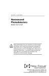
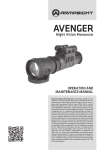
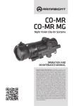
Models 1601 and 1611
User’s Manual
High-Speed Photoreceivers
Warranty
New Focus, Inc. guarantees its products to be
free of defects for one year from the date of shipment. This is in lieu of all other guarantees,
expressed or implied, and does not cover incidental or consequential loss.
Contents Warranty
Introduction
4
Theory
5
Operation
9
Specifications
160118 Rev. F
2
2
11
Is a registered trademark of
New Focus Inc.
This Page intentionally left blank.
3
Introduction
The New Focus Models 1601 and 1611 1-GHz, lownoise photoreceivers address the needs of the photodetector community in the area of low-noise,
high-gain, RF photoreception. These photoreceivers are AC coupled and are capable of driving
up to 1 V peak to peak into a 50-Ω load. The minimum bandwidth is 1 GHz with a current gain of
700 V/A.
The performance of these units is achieved
through the use of solid RF design together with
the implementation of some of the latest advances
in commercially available amplifier chips. The
detector is shielded to avoid RF pickup. New Focus
offers two models to match your different wavelength requirements.
These photoreceivers have very large gain×bandwidth products, low noise performance, high drive
capability and a large dynamic range. They will
enable wide bandwidth low-noise detection of signals distributed over fiber-optic cables or found in
high resolution spectroscopy, fiber-optic sensors,
optical metrology, and many other applications.
4
Theory
The Model 1601 photoreceiver consists of a silicon
PIN photodiode followed by a low-noise amplifier.
The Model 1611 photoreceiver consists of an InGaAs
PIN photodiode with the same amplifier.
The 1601 photodetector has a maximum current
of 5 mA and the 1611 photodetector has a maximum current of 10 mA. Therefore, the maximum
input optical power is 10 mW for both detectors.
The responsivity of the photodiode is shown in
Figs. 2a and 2b. Power is delivered through a connector on the back of the unit, and the entire package is shielded to eliminate RF pickup. Typical frequency responses for the Models 1601 and 1611 are
shown in Figs. 3a and 3b.
The amplifier is a low-noise, silicon amplifier having a voltage gain of 15 and an input impedance
of 50 Ω. This unit can be cascaded with other
50-Ω amplifiers.
Transmission lines connect the photodiode to the
amplifier and the amplifier to the output. Microstrip transmission lines are used to preserve speed
and eliminate parasitic inductance and capacitance that can cause ringing. Rise time of the
diode/amplifier combination is less than 400 ps.
The AC-coupled 1601 and 1611 incorporate blocking capacitors and a DC bias monitor circuit as
shown in Fig. 1. The corner frequency of the highpass filter on the AC-coupled output is approx. 30
kHz; the corner frequency of the low-pass filter on
the DC bias monitor output is approx. 20 kHz. The
DC bias monitor gain is 10 V/mA.
5
Fig. 1
Functional block diagram of the
Models 1601 and 1611.
10k Ω
Vb
I-V
+
Optical Input
Transimpedance
Amplifier
(low-speed)
DC Bias
Monitor
Output
G(f)
AC-coupled
Output
Transmission Line
6
Transmission Line
Fig. 2a
Responsivity of the photodiode
used in the Model 1601.
0.80
0.70
Responsivity, A/W
0.60
0.50
0.40
0.30
0.20
0.10
0.00
300
400
500
600
700
800
900
1000
Wavelength, nm
Fig. 2b
Responsivity of the photodiode
used in the Model 1611.
1.10
1.00
Responsivity, A/W
0.90
0.80
0.70
0.60
0.50
0.40
0.30
0.20
0.10
0.00
800
900
1000
1100
1200
1300
1400
1500
1600
1700
1800
Wavelength, nm
7
Fig. 3a
Typical frequency response of
the Model 1601.
4.0
2.0
Response, dB
0.0
-2.0
-4.0
-6.0
-8.0
-10.0
1
200
400
600
800
1000
1200
800
1000
1200
Frequency, MHz
Fig. 3b
Typical frequency response of
the Model 1611.
Response, dB
5.0
0.0
-5.0
-10.0
1
200
400
600
Frequency, MHz
8
Operation
To obtain optical input:
1. Plug one end of the power cable on to the connector on the back of the module and the other
end into a ±15-V power supply. (We recommend
the New Focus Model 0901 power supply.) Turn
on the supply.
Two different power cables have been shipped
with your detector: a New Focus Model 0921
banana plug-to-microconnector cable and a
Model 0922 microconnector-to-microconnector
cable. If you have a New Focus Model 0901
power supply, use the Model 0922 cable on one
of the supply’s 0.3-A microconnector outputs. Do
not use the Model 0921 on the Model 0901 power
supply’s 0.1-A banana outputs since they do not
provide enough current for the receiver. Use the
Model 0921 cable only with a power supply other
than the 0901 providing a minimum of 0.25 A of
current on ±15 V. The convention of the three
banana plugs is:
Banana Plug
Red
Green
Black
Voltage
+15 V
COM/GND
-15 V
2. Turn on the optical beam.
3. For direct optical beam input, align the module
in front of the optical beam.
For fiber-optic cable input, connect the fiber9
optic input cable from your optical source to the
ST- or FC-input connector port on the front of
the module.
Note: To operate the receiver in the linear region,
keep the input power levels below the Input Power
specification on pages 11 and 12. (The Input
Power is wavelength dependent and is inversely
proportional to the responsivity.)
To set up the output connection:
1. If your RF measurement instrument has a male
connector, connect it directly to the SMA female
output connector (labeled “AC”) on the back of
the module or connect with the appropriate
cable.
If your instrument has a female connector, connect with the appropriate cable.
2. Monitor the DC bias on the output labeled “DC”
with the provided SMB-to-BNC cable.
10
Model 1601
Specifications
Dimensional
3.00 (76.2)
2.86 (72.6)
2.07
(52.7)
1.00
(25.4)
Distance from window
face to photodetector:
1601 0.8 mm
1611 0.5 mm
1.43
(36.3)
8-32 (M4) thread
DC bias output; SMB connector
SMA connector;
AC-coupled output
Power connector
Performance
Coupling:
AC
Bandwidth (3 dB):
30 kHz–1 GHz
Wavelength Range:
320–1000 nm
Photodiode Material: Silicon PIN
Photodiode Size:
400-µm diameter
Power Requirements: ±15 V DC; 300 mA
Risetime:
400 ps (est.)
Current Gain:
700 V/A
Input Noise Current: 16 pA/√Hz
N.E.P.
31 pW/√Hz (@760 nm)
Output Current:
10 mA (max into 50 Ω)
Input Power:
(Linear Operation)
2 mW (max @ 760 nm)
Input Power (CW):
10 mW (max w/o damage)
Dynamic Range:
>60 dB (typ)
Connectors
Input:
RF Output:
DC Bias Monitor:
FC, or direct
SMA
SMB
11
Model 1611
Specifications
Dimensional
3.00 (76.2)
2.86 (72.6)
2.07
(52.7)
1.00
(25.4)
Distance from window
face to photodetector:
1601 0.8 mm
1611 0.5 mm
1.43
(36.3)
8-32 (M4) thread
DC bias output; SMB connector
SMA connector;
AC-coupled output
Power connector
Performance
Coupling:
AC
Bandwidth (3 dB):
30 kHZ–1 GHz
Wavelength Range:
900–1700 nm
Photodiode Material: InGaAs PIN
Photodiode Size:
100-µm diameter
Power Requirements: ±15 V DC; 300 mA
Risetime:
400 ps (est.)
Current Gain:
700 V/A
Input Noise Current: 16 pA/√Hz
12
N.E.P.
20 pW/√Hz (@1.3 µm)
Output Current:
10 mA (max into 50 Ω)
Input Power:
(Linear Operation)
1 mW (max @ 1.3 µm)
Input Power (CW):
10 mW (max w/o damage)
Dynamic Range:
>60 dB (typ)
Connectors
Input:
RF Output:
DC Bias Monitor:
FC, or direct
SMA
SMB