1
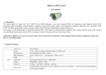
User’s manual
TDR DS6130
DS6130 Coaxial Cable
Fault Locator
(TDR)
User’s Manual
Ver. 1.0
Tianjin Deviser Electronics Instrument Co., LTD
No. 40, Yibin Road, Nankai District, Tianjin 300113
Tel: +86 22 2768 2088
+86 22 27645003 EXT 803
Fax:+86 22 27645002
Email: [email protected]
Website: www.devisertek.com
1
User’s manual
TDR DS6130
Warranty
The warranty period for this instrument is 18 months
after it is sold. The manufacturer or the agent is
responsible for the necessary commissioning and
testing.
Generally speaking, during the warranty period,
Deviser is responsible for all the repairs free of
charge unless the breakdown is caused by the
improper usage. The customer shall pay for the
transportation cost and insurance cost for sending
the product to the repair department, while the costs
of sending the repaired products to the customer
shall be borne by Deviser or the appointed repair
agent.
After the software and hardware provided by our
company for this product is properly installed on the
instrument, the instrument will carry out its
programming instructions. However, our company
does not guarantee that various operations on this
instrument will not be interrupted or no error
message appears.
The warranty is only limited to the instrument and
no warranty provided for the loss caused by the
2
User’s manual
TDR DS6130
breakdown of other equipment, loss of life or loss of
assets due to the improper use of this instrument.
Warranty Limitations
Our company does not provide warranty for the
improper usage or insufficient maintenance
(including the software or connections added by the
customer) as well as user disassembling the machine
without authorization. During 18 months warranty
period, calibration service, maintenance service and
consulting service are free of charge. Proper charges
for material or maintenance & repair service will
apply after 18 months warranty period.
Following items are not in the scope of warranty:
1. The battery and battery charger
presented as gifts upon machine
purchase.
2. The distortion and damage of the panel,
the switches, the devices and the outside
cover of the machine caused by the
mechanical external force (crash, fall etc.)
as well as the resulting breakdowns of
the internal components.
3. Disassemble the instrument attempting
to repair without authorization.
3
User’s manual
TDR DS6130
Attentions
The internal capacitors may still be electrically
charged after the instrument is powered off.
The technical specifications and operation methods
as stated in this user manual might be changed
without prior notice. If any further information is
needed after using the instrument for a while, please
consult with the manufacturer.
All the copyrights are reserved. No copy,
modification or translation without prior consents in
written.
4
User’s manual
TDR DS6130
Table of Content
1.
General Introduction of DS6130 ……………1
1.0 Brief Introduction...…………………… ……..1
1.1 Familiar the Equipment……………… ……...2
2. Operation Method of DS6130………… ……..5
2.0 Automatic Detection of Cable……… ………5
2.1 Manual Detection of Cable…………
……..12
2.2 Accession and Calibration of User’s Cable
types…………………………………...…...16
2.3 File…………………………………………...18
2.4 Setup………………………………………...21
2.5 Others……………………………………….24
3. Technical Specification……………………...25
5
User’s manual
TDR DS6130
1.General Introduction of DS6130
1.0 Brief Introduction
DS6130 applies the advanced TDR measuring
technique, it can display the cable failure using locus
format on the LCD, and locate the distance of the
failure points. It can be used in failure locating and
dimensional measuring. Characteristic as:
1、Displays all the drawing and character on
larger LCD, shows various measurement details
clearly.
2、The functions of files saving and printing,
convenient for the user to manage the data and
history inquiring
3、Unique zoom in/out functions can locate the
failure points precisely
6
User’s manual
TDR DS6130
1.1 Familiar the Equipment
Power on, emission pulse locus and parameter
status will display on the LCD (As shown in
Figure1-1), the parameter is using the display last
power off, the default range is 150m, impedance is
75Ω as power on.
Figure 1-1
1.
F1,F2,F3 Keys
Corresponding function of the LCD shows soft
keys. As Measuring Range, Impedance, Coefficient.
7
User’s manual
2.
TDR DS6130
Automatic Measurement
The instrument can search the failure points
automatically in fixed measuring range (150m ~
1600m), and display it on the LCD as locus formats,
at the same time, the mark will located the failure
distance automatically.
3.
Shift
Shift the F1、F2、F3 function keys on the LCD.
(As shown in Figure1-2)
Figure1-2
8
User’s manual
4.
TDR DS6130
Select
Changes the position of disable mark and
enable mark.
5.
Keys
Presses the
key to move the position of
mark.
6.
Keys
Changes the parameter value such as the
Measuring Range, Impedance, and Coefficient etc.
Attention:
Power on, enter the main interface (As
shown in Figure1-1, 1-2), and press the
keys to adjust the contrast of LCD.
9
User’s manual
TDR DS6130
2. Operation Method of DS6130
2.0 Automatic Detection for Cable
Fault
Firstly, connects measuring probe and cable for
testing, then turns on, presses the soft key F2
showing in Figure1-1, pops the impedance setup
interface (As shown in Figure2-1), presses
to
select the corresponding value with cable, F2 to
confirm.
Figure 2-1
10
User’s manual
TDR DS6130
Presses the F3 [COEFF] key, pop the type and
coefficient setup interface (As shown in Figure2-2),
press
to select the cable type, F2 to confirm.
Figure2-2
Presses Automatic Measuring,the system will
scan in turn base on 5 measure range, from large to
small in certain range. If finds the failure point, the
system will select the suited range, and put the mark
automatically (As shown in Figure 2-3), system
11
User’s manual
TDR DS6130
stops scanning at this moment.
Figure2-3
Illustration: Judgment of locus states: A rising
reflection denotes open circuit, Hi-impedance serial
or the cable have higher characteristic impedance
change. A falling reflection denotes short circuit,
“T”
connection
or
the
cable
have
lower
characteristic impedance change. Open circuit and
short circuit have more reflection, when the badness
connection or other slight disconnection, it has less
reflection
12
User’s manual
TDR DS6130
If there no reflection, may be the cable hasn’t
failure point, or the failure position has overstep the
current measuring range, the automatic measuring
minimum distance is 8m, if want to measure 5~7m,
please using manual measurement, select the 10m
measuring range.
1.Press F1 to switch zoom function
Zoom+: in the figure 2-3, press F1 to enter
zoom- state (As shown in Figure 2-4, soft key F1
change to “SHRNK”).
Figure2-4
13
User’s manual
TDR DS6130
The function can zoom+ the constrictive point
near by the dashed mark and move to the center
position of screen, top right corner is the series,
different measuring range has different zoom series.
Press
to zoom in gradually (As shown in
Figure2-5), press
to zoom out similarly. Adjust
keys to move the mark; it will locate the
failure points accurately.
Figure2-5
14
User’s manual
TDR DS6130
Zoom-: in the zoom+ state, press F1 to
renew the original location status (Figure 2-3).
moving mark
2.Press
Press
、
can change the dashed mark
position, at the same time, the distance of mark
position will show on the right bottom of screen.
Attention:
1、The highest input voltage of probe is 60V.
2、It is valid that the measure cable placed in
front of amplifier and divider.
3、Red probe connects the coaxial-cable’s
central line, black probe to the shield line of
outside screen. Insures connection tightness,
otherwise, influences the measure result.
15
User’s manual
TDR DS6130
2.1 Manual Detection of Cable Fault
Before measuring, user should set the
impedance and type just as automatic measurement,
manual searching failure point by pressing
[RANGE], [LOCAT],
keys.
1.In Figure1-1, press soft key F1, pop the
measuring range setup interface (As show in Figure
2-6), press
or
to select measuring
range you need. The measuring rang divided into:
10m、150m、450m、900m、1200m、1600m. Press
F2 key, thus system will scan and measure in the
measuring range user sets
Figure 2-6
16
User’s manual
TDR DS6130
2.Seeing the failure points on the screen, user
can press
to move the enable mark to the
right edge of failure points, read out the failure point
distance. (Annotate: user should fix the disable mark
to the left edge of emission pulse)
3.Presses Shift key to switch function key,
makes F1 soft key showing [LOCAT] (As show in
Figure 2-7). Presses [LOCAT] key, system will
locate the mark to the failure points automatically,
system will stop scanning at this moment.
Figure 2-7
17
User’s manual
4.User can press
TDR DS6130
to move mark; also
can use the zoom function of automatic measuring
method to locate accurately in last section.
5.If the reflection doesn’t occur in present
range, may be the failure points position have
overstep the measuring range, please change to the
next range. If the reflection does not occur in all
range, it is means that the cable has not failure point.
6.The 10m range is being set for about 5m to
10m failure points. Due to the distance between
emission pulse and failure reflection pulse is too
approach, please do not use the location function. If
the measuring distance is larger than 10m, it is better
to change to the next range.
18
User’s manual
TDR DS6130
2.2 Accession and Calibration of
user’s cable type
User can calibrate the system based on the
cable using condition,
1.Connects the measuring probe and 100m
standard cable open circuit in end, according to the
manual test method in 2.2 section, sets the [RANGE]
to 150m, then, moves the mark or presses [LOCAT]
to locate the failure points.
2.Presses F3 [COEFF] key to pop the wave
speed setting interface (As show in Figure2-2), press
to select the user cable type for calibration.
3.Presses
to change coefficient, the
distance will be changed along with changing
coefficient, after adjust the cable to 100m, presses
19
User’s manual
TDR DS6130
F2 [ENTER] key to finish the calibration. (The
coefficient is 0.5~0.99)
Attention:
1、Please unconnected such any equipment
such as divider 、 amplifier 、 connector etc.
Otherwise, the injustice will occur.
2 、 Don't change the coefficient without
calibrating the cable, otherwise, it will influence
the measuring accuracy, if user change the
coefficient unconsciously, please using [SETUP]
function to restore the default value out of
factory.
20
User’s manual
TDR DS6130
2.3 File
This function is used to save present measuring
image. Press Shift key to switch soft function key,
make F2 key showing [FILE] (As show in Figure
1-2), press this key, to enter the file system interface.
The system can save 6 files aggregately (As show in
Figure2-8, 2-9).
Figure 2-8
21
User’s manual
TDR DS6130
Figure 2-9
1.Save
Press soft key [SAVE] to save the interface
before entering file function, the new file will
overwrite the old one if there are files in system.
2.Load
Just as show in Figure 2-8, press soft key F2
[LOAD] to enter the load interface (As show in
Figure2-10). There are two functions, one is print,
and another is delete function.
22
User’s manual
TDR DS6130
Figure 2-10
(1) Print: connects EPSON-LQ300K printer,
passing the serial cable in the accessories, then
presses F2 [PRINT] to print current interface (As
show in Figure2-11).
(2)Del: delete the loaded files, if the file is
deleted, it does not restore.
23
User’s manual
TDR DS6130
Figure 2-11
2.4 Setup
Press shift key to switch soft function key,
make showing F3 soft key[SETUP] (As show in
Figure1-2). Press the key to enter function setup
interface (As show in Figure2-12), function setup
includes tow sub function, one is setting system data
and time, another is loading default function. Press
24
User’s manual
TDR DS6130
keys or the F2 soft key [▼▲] to select one in
the tow function.
Figure 2-12
(1) Load default:
Recovering all the type’s coefficient to the
system default value. After selecting, press F1
[ENTER] to execute.
(2) Date/Time:
Selecting DATE/TIME to look about the
25
User’s manual
TDR DS6130
present time. Press F1 [CHANGE] to adjust time(As
show in Figure 2-13), press F2[▼▲] at this time, to
select in editing time and date option. Press
to select Month/Date/Year or Hour/Minute/Second,
press
to change the value. After re-setting,
press F1 [ENTER] to confirm.
Figure 2-13
26
User’s manual
TDR DS6130
2.5 Others
1、Background light
Power on, the background light turns on
automatically, 4 minutes without any key pressed,
the background light turn off automatically, the
instrument works in energy saving model. If have
any key respond, background light will turn on
again.
2、Battery voltage inspection
System working, it inspects the batteries voltage
ceaselessly. When batteries voltage is too low, the
“LOW” will wink continuously, it is time to charge
the instrument, and otherwise, the instrument will
shut down soon.
3、LCD Contrast
27
User’s manual
TDR DS6130
In the main display (As show in Figure1-1, 1-2),
press
to adjust LCD contrast
3.Technical Specification
Measuring objects:
50Ω or 75Ωcoaxial-cable
Spec: 8 type’s factory style
SYWV-75-5(G.T),
SYWV.Y-75-7Z.GT,
SYWV-75-5S(G.T),
SYWY-75-9(T.L),
SYWV-75-5Z (G.T),
SYWY-75-9BZ(TL),
SYWV.Y-75-7.GT,
SYWY-75-12(T.L)
With 8 type user added
28
User’s manual
TDR DS6130
Measuring range and precision:
Measuring range:5m~1600m
Measure precision:1% of current measuring range
Resolution: Less than 1% of current measuring
range
Others:
Figuration size:190mm×80mm×152mm
Gross weight:600g
Working temperature:-10℃~+50℃
Storage temperature:-20℃~+70℃
Display:
128×128LCD
(With back light power source)
Battery:
7.2V 1.8AH Ni-MH batteries
Charger:
AC 90V~240V 50/60Hz
DC 9V-0.7A
Working time:average 7~8 hours(Full charge)
Charge time:More than 12 hours
29
User’s manual
TDR DS6130
Accessory:
Portable bag:
1
Special charger:
1
Measure probe:
2
specifications:
1
30