1
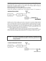
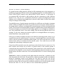
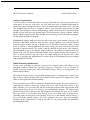
MFJ-931 Instruction Manual
Artificial RF Ground
MFJ ARTIFICIAL GROUND
IMPORTANT: Please read entire manual before attempting to operate this
equipment. This unit does not provide a DC electric ground. A
separate wire will need to be run from the transmitter to an
electric ground if it is not already available.
Thank you for purchasing the MFJ-931 ARTIFICIAL GROUND. The MFJ-931 creates an
artificial ground with a random length of wire thrown on the floor. This produces a tuned
counterpoise. Also, the MFJ-931 will electrically place a far away RF ground directly at our rig.
INSTALLATION AND OPERATION
Creating Artificial Ground
Connect your transmitter of antenna tuner to the binding post labeled "To Transmitter or
Antenna Tuner Chassis Ground" on the back of the MFJ-931.
Note: This wire needs to be as short as possible, preferably with the ground posts as close as
possible i.e., the units side by side or one on top of the other.
Attach the length of random wire to the red binding post labeled "To Counterpoise Wire or
Ground Connection Wire" on back of the MFJ-931. Be sure not to reverse these wires. The
random wire should be a quarter-wave length or less at the operating frequency. Be sure to
throw the random wire along the floor and to tape up the open end of the wire to avoid RF
burn.
To obtain maximum RF ground current for a low impedance RF ground, alternately adjust the
two controls on the front panel labeled "INDUCTANCE" and "CAPACITANCE". Turn the
INDUCTANCE control first until the highest amount of current can be registered on the built-in
AMMETER. Then adjust the CAPACITANCE control to increase the amount of RF current.
Try several inductance setting for best results. What if the needle goes off the scale or doesn't
move at all? Then the sensitivity of the Ammeter needs to be adjusted. Turn the SENSITIVITY
control until the needle is in the middle of the scale. Then readjust the INDUCTANCE control
for the highest amount of RF current and use the CAPACITANCE control to achieve
maximum RF current. If the needle is still off scale or zero, readjust the SENSITIVITY control
and repeat the tuning process
MFJ-931 Instruction Manual
Artificial RF Ground
until maximum RF current is achieved. After maximum RF current is reached, retune your
antenna tuner for minimum SWR. You may need to retune both the MFJ-931 and your
antenna tuner several times to achieve best results.
Electrically Placing Your Far Away RF Ground at Your Radio
Connect your transmitter or antenna tuner to the binding post labeled "To Transmitter or
Antenna Tuner Chassis Ground" on the back of the MFJ-931 with the shortest possible
wire(s). If necessary, place the MFJ-931 and your transmitter or antenna tuner side by side or
one on top of the other to insure the ground of each are as close to each other as possible.
Connect your existing ground wire to the red binding post labeled "To Counterpoise Wire
or Ground Connection Wire" on the back of the MFJ-931. Do not reverse these wires. After
making these connections, follow the same procedure for
maximizing RF ground current as described in the Creating Artificial Ground section.
After maximum RF current is reached, retune your antenna tuner for minimum SWR. You may
need to retune both your antenna tuner and the MFJ-931 several times to achieve best results.
WARNING: This unit does not provide a DC electric ground. A separate wire will
need to be run from the transmitter to an electric ground if it is not
already available.
MFJ-931 Instruction Manual
Artificial RF Ground
Failure to Obtain a Ground Reading
If a ground current reading cannot be obtained at full transmitting power, the counterpoise or
ground may not generate sufficient current at the operating frequency. If no RFI problems exist,
set the CAPACITANCE control to zero, and the INDUCTANCE control to "A" and operate. If
you experience RF in the shack or other problems, alter the counterpoise or add a different
length of wire. The wire for a counterpoise should be a quarter wavelength at the lowest
frequency used. Additional short lengths may be placed for other bands if needed. More radials
will give a stronger current reading.
You should be aware of typical antenna current behavior at different wavelengths. An antenna
which is a half wavelength will not show any ground current at exactly the resonant frequency.
An antenna which is a quarter wavelength at the resonant frequency will show maximum ground
current. The amount of current through the ground wire depends entirely on the antenna system.
The odd wavelengths give maximum current reading, and the even wavelengths are minimum or
zero. Zero current draw shows a zero meter reading. This does not mean that the meter is not
working. Try the same antenna on at least an eighth of a wavelength difference in frequency,
which should show some ground current.
In the case of a halfwave antenna, the meter is not usable for measuring ground current, so it is
very difficult to tune the artificial ground. You may use a field strength meter, such as the MFJ812B, to tune the ground for maximum radiated signal. This also means that the receiving
station S-units will go to maximum for this antenna system. You would also use the field
strength meter when tuning a counterpoise system.
Using the artificial ground to tune the ground may not be obvious if you are a new user. You
must visualize and account for all sources of ground current. If the artificial ground is
connected into the ground lead of the transmitter, and a ground wire is also connected to the
ground lead of the amplifier or tuner, then the artificial ground is effectively shorted out, and no
ground current will show on the meter. You must install the MFJ-931 in series with the ground
system.
Visual tool: A station is positioned a mile higher than the ground rod. A ground wire runs
from the ground rod to the station. The ground wire will show very high resistance and radiation
instead of conducting current to the ground rod. The MFJ-931 tunes the wire for low
resistance at the antenna system resonant frequency so that the antenna system may develop
maximum current. This in turn provides maximum radiated power from the antenna system.
Without the MFJ-931, the wire makes a better antenna than a ground wire.
MFJ-931 Instruction Manual
Artificial RF Ground
Using a Counterpoise
If you are unable to connect the station to any type of ground wire, then you may still use the
counterpoise to increase your signal. As more and more wire is installed underneath an
antenna, the signal strength will increase. This will continue until a maximum occurs. Only one
wire installed along the floor is enough to make a very noticeable improvement in signal
strength. The counterpoise reflects radiated energy, which would normally be absorbed by the
ground as heat, back above the ground plane. This redirection of energy combines with the
primary radiated signal as usable field strength. Received energy bounces off of the counterpoise
into the antenna along the reverse path.
Visual tool: A lighted candle on a table in a dark room emits a given amount of energy in all
directions. Light which reaches the walls will have a given brightness. You could say that this
would be signal strength. Energy is broadcast in all directions around the candle, up and
down. If a mirror is inserted underneath the candle, energy previously absorbed by the table
(ground) is radiated upward. The result is that the amount of light on the walls increases.
The transmitted energy is not changed, simply redirected. The amount of signal increase will
depend on the area of reflection. Beyond a certain area, no further increase will be noticed. A
sliver of mirror placed on only one side of the candle would give an increase only in that
direction. A ground plane underneath a HT rubber ducky will tremendously increase radiated
field strength from the radio.
Radio Frequency Interference
In may cases, providing an adequate ground to the antenna system will reduce or stop
unwanted radiation outside the operating frequency. Harmonics can be directed to
ground, or simply become part of the main radiated energy. This gives the appearance of a
cleaner signal on the air.
RFI can also increase by use of a grounded antenna system. A common belief, which is not
true, is that an artificial ground will remove all RFI from the station. RFI suppression is a side
effect of a clean signal, not a universal solution.
The most common type of RFI is commonly called front-end overload. This results whenever a
semiconductor junction comes into contact with an AC (RF) signal and rectifies it. Any
diode, transistor, or IC can rectify RF and mix it internally with any other signal present. More
signal present raises the level of mixing in the semiconductor junction. The higher signal
present can be a result of the increased field strength of the antenna. The only way to remove
this type of RFI is by shielding and filtering of the received RF in the receiving device.
Grounding of the receiving device case can help. If the case is non-metallic, then RF energy is
free to invade the internal circuitry. Any wires attached to the device may act as antennas.
Installing an RF suppression kit, such as the MFJ-701, can greatly reduce the interference
traveling up these lines.
MFJ-931 Instruction Manual
Artificial RF Ground
Installing a ground in the wrong fashion, such as mistuning and bad connections, can also
generate additional RFI. Harmonics and loss of signal strength can be the result. Energy outside
the band may become great enough to radiate into the commercial radio and TV bands.
Installing a low pass filter, such as the MFJ-704, will provide additional suppression of the outof-band signal.
TECHNICAL ASSISTANCE
If you have any problem with this unit first check the appropriate section of this manual. If the
manual does not reference your problem or your problem is not solved by reading the manual,
you may call MFJ Technical Service at 662-323-0549 or the MFJ Factory at 662-323-5869.
You will be best helped if you have your unit, manual and all information on your station handy so
you can answer any questions the technicians may ask.
You can also send questions by mail to MFJ Enterprises, Inc., 300 Industrial Park Road,
Starkville, MS 39759; by Facsimile (FAX) to 662-323-6551; or by email to
[email protected]. Send a complete description of your problem, an explanation of
exactly how you are using your unit, and a complete description of your station.