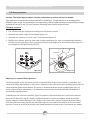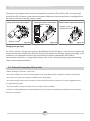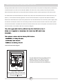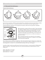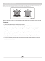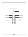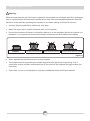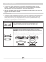
1
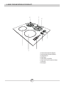
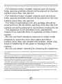
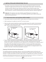
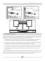
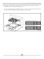
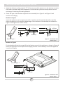
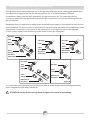
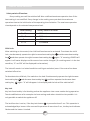
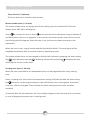
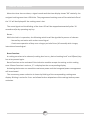
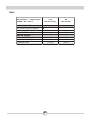
HBE 2I2G FV
Language
Code
OPERATING AND INSTALLATION
INSTRUCTIONS OF
BUILT-IN HOB
Dear Customer,
Our goal is to offer you products with high quality that exceed your expectations.
Your appliance is produced in modern facilities carefully and particularly tested for
quality.
This manual is prepared in order to help you use your appliance that is manufactured
by the most recent technology, with confidence and maximum efficiency.
Before using your appliance, carefully read this guide that includes the basic
information for right and safe installation, maintenance and use. Please contact to
the nearest Authorized Service for the installation of your product.
CE Declaration of conformity
This appliance has been designed to be used only for home cooking. Any other use
(such as heating a room) is improper and dangerous.
This appliance has been designed, constructed, and marketed in compliance with:
•
Safety requirements of the "Gas" Directive 2009/142/EC;
•
Safety requirements of the "Low voltage" Directive 2006/95/EC;
•
Safety requirements of the "EMC" Directive 2004/108/EC;
•
Requirements of the Directive 93/68/EC.
CONTENTS:
1. BRIEF PRESENTATION OF PRODUCT
2. WARNINGS
3. INSTALLATION AND PREPARATIONS FOR USE
3.1 Environment where your appliance will be installed
3.2 Installation of product
3.3 Gas connection
3.4 Gas conversion
3.5 Electrical Connection Of Your Hob
4. USE OF YOUR PRODUCT
4.1 Use of gas burners
4.2 Control of the hob burners
4.3 Control Panel for 4 induction heaters
4.4 Control of the induction heaters
4.5 Accesorries
5. CLEANING AND MAINTENANCE
5.1 Cleaning
5.2 Maintenance
6. SERVICE AND TRANSPORT
6.1 Basic troubleshooting before contacting service
6.2 Information related to the transport
Note: All figures in manual are schematic.
2
1. BRIEF PRESENTATION OF PRODUCT
4
3
8
7
5
1
6
2
1- Induction Heating Element (160 mm)
2- Induction Heating Element (200 mm)
3- Semirapid Burner
4- Rapid Burner
5- Control Knobs for gas hobs
6- Touch Control Panel for Induction Heaters
7- Hob Surface
8- Pan Support
3
PART 2 SAFETY WARNINGS
READ THESE INSTRUCTIONS CAREFULLY AND COMPLETELY BEFORE USING YOUR
APPLIANCE, AND KEEP IT IN A CONVENIENT PLACE FOR REFERENCE WHEN NECESSARY.
THIS MANUAL IS PREPARED FOR MORE THAN ONE MODEL IN COMMON. YOUR APPLIANCE
MAY NOT HAVE SOME OF THE FEATURES THAT ARE EXPLAINED IN THIS MANUAL. PAY
ATTENTION TO THE EXPRESSIONS THAT HAVE FIGURES, WHILE YOU ARE READING THE
OPERATING MANUAL.
General Safety Warnings
- This appliance can be used by children aged from 8
years and above and persons with reduced physical,
sensory or mental capabilities or lack of experience
and knowledge if they have been given supervision or
instruction concerning use of the appliance in a safe
way and understand the hazards involved. Children
shall not play with the appliance. Cleaning and user
maintenance shall not be made by children without
supervision.
- WARNING: The appliance and its accessible parts
become hot during use. Care should be taken to avoid
touching heating elements. Children less than 8 years
of age shall be kept away unless continuously
supervised.
- WARNING: Unattended cooking on a hob with fat or
oil can be dangerous and may result in fire. NEVER
try to extinguish a fire with water, but switch off the
appliance and then cover flame e.g. with a lid or a fire
blanket.
- WARNING: Danger of fire: do not store items on the
cooking surfaces.
- WARNING: If the surface is cracked, switch off the
appliance to avoid the possibility of electric shock.
4
PART 2 SAFETY WARNINGS
- For induction hobs, metallic objects such as knives,
forks, spoons and lids should not be placed on the hob
surface since they can get hot.
- For induction hobs, metallic objects such as knives,
forks, spoons and lids should not be placed on the hob
surface since they can get hot.
- For hobs incorporating a lid, any spillage should be
removed from the lid before opening. And also the hob
surface should be allowed to cool before closing the lid.
- The appliance is not intended to be operated by
means of an external timer or separate remote-control
system.
- Do not use harsh abrasive cleaners or sharp metal
scrapers to clean the oven door glass and other
surface since they can scratch the surface, which may
result in shattering of the glass or damage to the
surface.
- Do not use steam cleaners for cleaning the appliance.
-Your appliance is produced in accordance with all applicable local and international standards and
regulations.
- Maintenance and repair work must be made only by authorized service technicians. Installation and
repair work that is carried out by unauthorized technicians may endanger you. It is dangerous to alter or
modify the specifications of the appliance in any way.
- Prior to installation, ensure that the local distribution conditions (nature of the gas and gas pressure or
electricity voltage and frequency) and the requirements of the appliance are compatible. The
requirements for this appliance are stated on the label.
- CAUTION: This appliance is designed only for cooking food and is intended for indoor domestic
household use only and should not be used for any other purpose or in any other application, such as
for non-domestic use or in a commercial environment or room heating.
- This appliance is not connected to a combustion products evacuation device. It shall be installed and
connected in accordance with current installation regulations. Particular attention shall be given to the
relevant requirements regarding ventilation.
- If after 15 s the burner has not lit, stop operating the device and open the compartment door and/or
wait at least 1 min before attempting a further ignition of the burner.
5
PART 2 SAFETY WARNINGS
- These instructions are only valid if the country symbol appears on the appliance. If the symbol does
not appear on the appliance, it is necessary to refer to the technical instructions which will provide the
necessary instructions concerning modification of the appliance to the conditions of use of the country.
- All possible security measures have been taken to ensure your safety. Since the glass may break,
you should be careful while cleaning to avoid scratching. Avoid hitting or knocking on the glass with
accessories.
- Ensure that the supply cord is not wedged during the installation. If the supply cord is damaged, it
must be replaced by the manufacturer, its service agent or similarly qualified persons in order to
prevent a hazard.
Installation Warnings
- Do not operate the appliance before it is fully installed.
- The appliance must be installed by an authorized technician and put into use. The producer is not
responsible for any damage that might be caused by defective placement and installation by
unauthorized people.
- When you unpack the appliance, make sure that it is not damaged during transportation. In case of
any defect; do not use the appliance and contact a qualified service agent immediately. As the
materials used for packaging (nylon, staplers, styrofoam...etc) may cause harmful effects to children,
they should be collected and removed immediately.
- Protect your appliance against atmospheric effects. Do not expose it to effects such as sun, rain,
snow etc.
- The surrounding materials of the appliance (cabinet) must be able to withstand a temperature of min
100°C.
During usage
- Do not put flammable or combustible materials, in or near the appliance when it is operating.
- Do not leave the cooker while cooking with solid or liquid oils. They may catch fire on condition of
extreme heating. Never pour water on to flames that are caused by oil. Cover the saucepan or frypan
with its cover in order to choke the flame that has occured in this case and turn the cooker off.
- Always position pans over the centre of the cooking zone, and turn the handles to a safe position so
they cannot be knocked or grabbed.
- If you will not use the appliance for a long time, plug it off. Keep the main control switch off. Also
when you do not use the appliance, keep the gas valve off.
- Make sure the appliance control knobs are always in the "0" (stop) position when it is not used.
- CAUTION: The use of a gas cooking appliance results in the production of heat, moisture and
products of combustion in the room in which it is installed. Ensure that the kitchen is well ventilated
especially when the appliance is in use, keep natural ventilation holes open or install a mechanical
ventilation device (mechanical extractor hood).
- Prolonged intensive use of the appliance may call for additional ventilation, for example opening of a
window, or more effective ventilation, for example increasing the level of mechanical ventilation where
present.
During cleaning and maintenance
- Always turn the appliance off before operations such as cleaning or maintenance. You can do it after
plugging the appliance off or turning the main switches off.
- Do not remove the control knobs to clean the control panel.
TO MAINTAIN THE EFFICIENCY AND SAFETY OF YOUR APPLIANCE, WE RECOMMEND YOU
ALWAYS USE ORIGINAL SPARE PARTS AND TO CALL ONLY OUR AUTHORIZED SERVICE
AGENTS IN CASE OF NEED.
6
3. INSTALLATION AND PREPARATIONS FOR USE
This modern, functional and practical cooker, that was manufactured with the parts and
materials of highest quality, will meet your cooking needs in every aspect. You must surely
read this manual so that you don't have any problem in future and to be able to have
satisfactory results. The following information are the required rules for right installation and
service processes. It must be read especially by the technician who will install the appliance.
! Important: This appliance must be installed by a qualified people according to the
manufacturers installation instructions, local building regulations, gas authority codes and
electrical wiring instructions.
3.1. Environment where your appliance will be installed
• Your product must be set up and used in a place where it will always have ventilation.
• While operating, this appliance needs 2m3/h air per kw input.
• There must be a natural ventilation enough to provide the gas to be used in the environment.
The average air flow must directly come in through the air holes that will be opened on the
walls that are opened towards outside.
Air inlet section
min. 100cm2
Air inlet section
min. 100cm2
Figure 2
Figure 1
• These air holes must have at least the effective cross section of 100cm2 for fresh air circulation
(One or more air holes can be opened.). This hole (or holes) must be opened so that they
shouldn't be blocked. Preferably they must be placed close to the bottom and at opposite side of
the smokes of the burned gases that were emptied. If it seems not possible to open these
ventilations in the place where the appliance is set up, the needed air can also be obtained
through the next room, provided that this place is not a bedroom or a dangerous place. In this
case this “next room” must also be ventilated as required.
Emptying of the Burned Gases from Environment
The cooking appliances that operate with gas, throw the burned gas wastes out directly to the
outside or through the cooker hoods that are connected to the a chimney that opens directly to the
outside. If it seems not possible to install a cooker hood, it is required to set an electric fan on the
window or wall that has access to fresh air. This electric fan must have the capacity to change the air
of the kitchen environment 4-5 times of its own volume of air per hour.
7
INSTALLATION AND PREPARATIONS FOR USE
Cooker hood
flue
Electrical ventilator
Air inlet section
2
min. 100cm
Air inlet section
2
min. 100cm
Figure 3
Figure 4
Min. 60cm
Min. 42cm
Min. 70cm(without hood)
Min. 65cm(with hood)
Min. 42cm
COOKER HOOD
Figure 5
3.2 Installation of product
There are some factors that must be paid attention to while installing your product. Surely be very
careful to while installing your product. Pay attention to our below instructions in order to be able
to prevent any problems and/or dangerous situations that may occur later.
• The appliance can be placed close to other furniture on condition that in the area where the
oven is set up, the furniture's height does not exceed the height of the cooker panel.
• Pay attention not to place it near the refrigerator, there must be no flammable or inflammable
materials such as curtain, waterproof cloth, etc. that will begin to burn quickly.
• It is required that there must be least a 2cm blank space around the product for air circulation.
• The furniture close to product must be manufactured resistant to temperatures up to 100°C.
• If the kitchen furniture are higher than the cooktop, it must be at least 10cm away from the
cooker's side.
The minimum heights from the pan support and wall cupboards to cooker hoods with fan over the
product, are shown in figure 5. Thus, the cooker hood must be at minimum 65cm height from the
pan support. If there is no cooker hood, this height must not be less than 70cm.
8
INSTALLATION AND PREPARATIONS FOR USE
The appliance is supplied with an installation kit including adhesive sealing material and fixing
brackets&screws are included with the appliance.
• Cut the aperture dimensions as indicated in Figure - 1. Locate the aperture on the worktop such
that after the hob is installed the following reguirements are ensured;
m
0m
51
580 m
m
42 mm
Min.
B
Min.
25mm
560 m
If your appliance have five hobs ;
Neighbourhood walls A[mm] B[mm]
Combustible
60
150
Non-combustible
40
100
Min.
A
m
m
0m
If your appliance have four hobs ;
Neighbourhood walls A[mm] B[mm]
Combustible
60
150
Non-combustible
50
40
49
Min
130 .
mm
Figure 6
9
INSTALLATION AND PREPARATIONS FOR USE
• Apply the adhesive sealing material “C” all the way round the aperture on the worktop to match
the outher perimeter edge of the appliance. Ensure that the junctions overlap at the corners
and no gap is left along the sealing material.
• Check the type of the brackets supplied in the assembly kit in Figure-2 and Figure-3 and
continue accordingly;
Brackets of Type-1
Insert the appliance into the aperture and fix in position via the brackets (A) and screws (B).
Adjust the position of the brackets depending on the thickness of the worktop as indicated in
Figure-2 and tighten the screws evenly.
C
C
t<25mm
Tt
A
Hob
Worktop
B
t>25mm
Tt
B
A
Figure 7 - Installation with
Bracket Type 1
Bracket Type 1
Brackets of Type-2
Fix the brackets (A) via the screws (B) on the bottom cover of the appliance as shown in Figure-8.
Insert the appliance into the aperture and apply pressure on the cooktop, ensure the appliance
is positioned tightly.
Bracket Type 2
C
Worktop
Hob
B
A
Figure 8 - Installation with
Bracket Type 2
10
INSTALLATION AND PREPARATIONS FOR USE
• Carefully trim away the excess sealing material “C” from around the appliance.
! Important: If the appliance is to be installed above a cupboard or drawer it is absolutely
essential that you place a seperator between the base of the appliance and the drawer unit.
3.3. Gas connection
Assembly of gas supply and leakage check
The connection of the appliance should be performed in accordance with local and international
standards and regulations applicable. You can find the information related to appropriate gas types
and appropriate gas injectors on technical data table. If the pressure of used gas is different than
these values stated or not stable in your area, it may be required to assemble an available pressure
regulator on the gas inlet. It is certainly required to contact to the authorized service to make these
adjusments.
The points that must be checked during flexible hose assembly
If the gas connection is made by a flexible hose that is fixed on the gas inlet of appliance, it must be
fixed by a pipe collar as well. Connect your appliance with a short and durable hose that is as close
as possible to the gas source. The hose's permitted maximum lenght is 1.5m. The hose that brings
gas to the appliance must be changed once a year for your safety.
The hose must be kept clear from areas that may heat up to temperatures in excess of 900C. The
hose must not be ruptured, bent or folded. It must be kept clear of sharp corners, moving things,
and should not be defective. Before assembly, it must be checked whether there is any production
defect.
As gas is turned on, all connection parts and hose must be checked with soapy water or leakage
fluids. Do not use naked flame to check gas leakage. All metal components used during gas
connection must be clear of rust. Also check the expiry dates of components to be used.
The points that must be checked during fixed gas connection assembly
To assemble a fixed gas connection (gas connection made by threads, e.g. a nut), there are different
methods used in different countries. The most common parts are already supplied with your appliance.
Any other part can be supplied as spare part.
11
INSTALLATION AND PREPARATIONS FOR USE
During connections always keep the nut on the gas manifold fixed, while rotating the counter-part.
Use spanners of appropriate size for safe connection. For all surfaces between different
components, always use the seals provided in the gas conversion kit. The seals used during
connection should also be approved to be used in gas connections. Do not use plumbing seals for
gas connections.
Remember that this appliance is ready to be connected to gas supply in the country for which it has
been produced. The main country of destination is marked on the rear cover of the appliance. If you
need to use it in another country, any of the connections in the figure below can be required.
In such a case, contact local authorities to learn the correct gas connection.
Gas Pipe
Seal
Hose
Fitting
Hose
Fitting
Gas Hose
with Collar
Gas Pipe
Gas Pipe
Seal
Seal
Hose
Fitting
Gas Hose
with Collar
Hose
Fitting
Mechanical
Gas Hose
Gas Pipe
Seal
Hose
Fitting
Gas Pipe
Hose
Fitting
Mechanical
Gas Hose
Mechanical
Gas Hose
Hose
Fitting
Figure 9
It is required to call the authorized service to be able to make the gas connections appropriately
and in compliance with safety standards.
!
ATTENTION! Surely do not use any match or lighter for control of gas leakage.
12
INSTALLATION AND PREPARATIONS FOR USE
3.4 Gas conversion
Caution: The following procedures must be undertaken by authorized service people.
Your appliance is adjusted to be operated with LPG/NG gas. The gas burners can be adapted to
different types of gas, by replacing the corresponding injectors and adjusting minimum flame length
suitable to the gas in use. For this purpose, following steps should be performed:
Changing injectors:
• Cut off the main gas supply and unplug from the electric mains.
• Remove the burner cap and the adapter(Figure 6).
• Unscrew the injectors. For this, use a 7mm spanner(Figure 7).
• Replace the injector with the ones from the gas conversion kit, with corresponding diameters
suitable to the type of gas that is going to be used, according to the information chart (which is
also supplied in the gas conversion kit).
Spanner
Injector
Figure 11
Figure 10
Adjusting the reduced flame position:
The flame length in the minimum position is adjusted with a flat screw located on the valve. For
valves with flame failure device, the screw is located on the side of the valve spindle(Figure 8-9). For
valves without flame failure device, the screw is located inside the valve spindle(Figure 10). For
easier reduced flame adjustment, it is advised to remove the control panel (and microswitch, if
present) during adjustment.
To determine the minimum position, ignite the burners and leave them on in minimum position.
Remove the with the help of a small screwdriver fasten or loosen the bypass screw around 90
angular degrees. When the flame has a length of at least 4mm, the gas is well distributed. Make
sure that the flame does not die out when passing from the maximum position to the minimum
position. Create an artificial wind with your hand toward the flame to see if the flames are stable.
13
INSTALLATION AND PREPARATIONS FOR USE
The position the bypass screw must be loosened for conversion from LPG to NG. For conversion
from NG to LPG, the same screw must be fastened. Make sure that the appliance is unpluged from
the electric mains and the gas supply is open.
Valve with flame failure device
Valve with flame failure device
Valve without flame failure device
Bypass screw
Bypass screw
(Inside the hole)
Bypass screw
Figure 13
Figure 12
Figure 14
Changing the gas inlet:
For some countries, the gas inlet type can be different for NG/LPG gases. In such a case, remove the
current connection components and nuts (if any) and connect the new gas supply accordingly. In all
conditions, all components used in gas connections should be approved by local and/or
international authorities. In all gas connections, refer to the “Assembly of gas supply and leakage
check” clause explained before.
3.5 Electrical Connection Of Your Hob
Before making a connection, check that:
· The mains voltage is the same as that quoted on the rating plate which is situated at the back of your hob.
· The circuit can support the appliance load (see the rating plate).
· The power supply has an earth connection, which complies with the provisions of current regulations and
is in good working order.
· The fused switch is easily accessible once the hob has been installed.
If there is no dedicated hob circuit and fused switch, they must be installed by a qualified electrician before
the hob is connected.
14
INSTALLATION AND PREPARATIONS FOR USE
An approved suitable cable must be connected from the Consumer Unit (main fuse box) and be protected by
its own 32amp fuse or Micro Circuit Breaker (MCB). The electrician must provide a fused all pole switch,
which disconnects both the line (live) and neutral conductors with a contact seperation of at least 3,0 mm.
The fused switch should be fitted to the kitchen wall, above the worksurface and to the side of the hob, not
above it, in accordance with IEE regulations. Connect the fused switch to a junction box which should be
fitted on the wall about 61cm (24 inches) above floor level and behind the hob. The hob's power supply cable
can then be connected. Connect one end to the junction box and connect the other end to the hob's power
connection box which is located at the back of the hob. Remove the cover of the power connection box and
install the cable, in accordance with the connection diagram.
L
N
BLUE
YELLOW+GREEN
BROWN
Electrical connection diagram
For the induction hob, the cable must be
H05VV-F 3X1,5 mm² 60227 IEC 53 ••.
You will find the connection diagram
shown on the bottom of your appliance.
3X1,5 mm 2, H05V V-F
power supply cable must be used.
The earth wire must be connected
to screw with symbol.
15
4. USE OF YOUR PRODUCT
4.1 Use of gas burners
Ignition of the burners
To determine which knob controls which burner, check the position symbol above the knob.
•
Manual Ignition
If your appliance is not equipped with any ignition aid or in case there is a failure in the electric
network, follow the procedures listed below:
To ignite one of the burners, press and turn its knob counter-clockwise so that the knob is in
maximum position, approach a match, taper or another manual aid to its upper circumference.
Move the ignition source away as soon as you see a stable flame.
•
Electrical Ignition
Electrical ignition of gas burners can be performed in two ways; depending on the configuration of
your appliance.
Figure 15
Ignition by Spark Button: Press the valve of the burner you want to
operate and turn the valve in the counter-clockwise direction so that the
knob is in maximum position and with your other hand, press the ignition
button (Figure 11) at the same time. Press the ignition button
immediately, because if you wait, a build up of gas may cause the flame to
spread. Continue pressing the ignition button until you see a stable flame
on the burner.
Ignition by Hob Control Knob: Press the hob control knob of the burner you want to operate and
turn the hob control knob in the counterclockwise direction so that the knob is in maximum
position while keeping the knob pressed. The spark plugs will generate sparks as long as you keep
the control knob pressed. The micro switch placed under the knob will automatically create sparks
through the spark plug of the burner. Continue pressing the knob until you see a stable flame on
the burner.
Flame safety device:
Hob Burners (If your hob is equipped with gas safety device)
Hobs equipped with flame failure device provide security in case of accidentally extinguished flame.
If such a case occurs, the device will block the burners gas lines and will avoid any accumulation of
unburned gas. Wait 90 seconds before re-igniting an extinguished gas burner.
16
USE OF YOUR PRODUCT
4.2 Control of the hob burners
Control of the hob burners
OFF position
MAX. position
MIN. position
MODULATE
Figure 16
The knob has 3 positions: Off (0), maximum (big flame symbol) and minimum (small flame symbol).
After you ignite the burner in maximum position; you can adjust the flame length between
maximum and min. positions. Do not operate the burners when the knob position is between
maximum and off positions.
After the ignition, check the flames visually. If you see yellow
tip, lifted or unstable flames; turn the gas flow off, and check
the assembly of burner caps and crowns (Figure 17). Also,
make sure that no liquid has flown into the burner cups. If
the burner flame goes out accidentally, turn the burner off,
ventilate the kitchen with fresh air, and do not attempt reignition for 90 sec.
Cap
Crown
Spark
Plug
Burner
Cup
Figure 17
When turning the hob off, turn the knob in the clockwise
direction so that the knob shows "0" position or the marker
on the knob points upwards.
Your hob has burners of different diameters. The most economic way of using gas is to choose the
correct size gas burners for your cooking pan size and to bring the flame to minimum position once
the boiling point is reached. It is recommended to always cover your cooking pan.
In order to obtain maximum performance from the main burners, use pots with the following flat
bottom diameters. Using smaller pots than the minimum dimensions stated below will cause
energy loss.
Rapid / Wok Burner: 22-26cm
Semi-rapid Burner: 14-22cm
Auxiliary Burner: 12-18cm
17
USE OF YOUR PRODUCT
Make sure that the tips of the flames do not spread out of the outer circumference of the pan, as
this may also harm the plastic accessories around the pan (handles etc.).
Figure 18
When the burners are not in use for prolonged periods, always turn the main gas control valve off.
! Warning:
•
Use only flat pans and with a sufficiently thick base.
•
Ensure that the base of the pan is dry before placing it on the burners.
•
The temperature of accessible parts may be high when the appliance is operating. So it is
imperative to keep children and animals out of the reach of the burners during and after
cooking.
•
After use, the hob remains very hot for a prolonged period of time, do not touch it and do not
place any object on top of the hob.
•
Never place knives, forks, spoons and lids on the hob as they will get hot and could cause
serious burns.
•
Do not use cooking containers that protrude from the cookers' table andwhich are likely to
overheat the control levers
18
USE OF YOUR PRODUCT
4.3. Control Panel for Induction Heaters
Timer
Left Increase
heat setting/timer
Right Increase
heat setting/timer
Left Decrease
heat setting/timer
Right Decrease
heat setting/timer
Key Lock
Indicator
Key Lock
Smart Pause
On/Off
Boost
19
USE OF YOUR PRODUCT
4.4. Control of the induction heaters
Use the induction cooking zones with suitable cookware.
After mains voltage is applied, all displays are come on for a moment. When this time is over, the
hob is in the stand-by mode and it is ready for operation.
The hob is controlled with electronic sensors which are operated by touching the related sensors.
Each sensor activation is followed by a sound signal (buzzer).
Switching the appliance on:
Switch the hob on by touching ON/OFF key
. All heater displays show a static "0" and the
bottom right dots blink. (If no cooking-zone is selected within 20 seconds, the hob will
automatically turn off.)
Switching the appliance off:
Switch the hob off at any time by touching
ON/OFF key
.
has always priority in the switch off function.
Switching the cooking-zones on:
Touch the related increase heat setting key
you wish to cook on. There is a static dot
indication on the selected heater display and the blinking dot on all other displays extinguish.
Select the temperature setting by using the related increase heat setting key
setting key
or decrease heat
. The element is now ready to cook on. For quickest boil times, select desired
cooking level and then touch the P key to activate Boost function.
Switching the cooking-zones off:
Select the element you want to switch off by pressing the related increase heat setting key.
Using
key, turn the temperature down to ''0''. (Also using
turns the temperature to ''0'')
If the cooking zone is hot, "H" will be displayed instead of "0".
20
and
keys simultaneously
USE OF YOUR PRODUCT
Switching all cooking-zones off:
To turn all the cooking zones off at once, touch the
key.
In the stand-by mode, an "H" appears on all cooking zones which are hot.
Residual heat indicator:
Residual heat indicator indicates that the glass ceramic has a dangerous touch
temperature in the circumference of a cooking zone.
After switching off the cooking zone, the respective display shows "H" until the assigned
cooking zone temperature is in an uncritical level.
Smart Pause
Smart Pause, when activated, reduces the power of all burners that have been switched
on.
If you then deactivate the Smart Pause, the heaters will automatically return to the
previous level.
If the Smart Pause is not de-activated, the cooktop will turn off after 30 minutes.
Touch (
) to activate Smart Pause. The power for the activated heater(s) will reduce to
level 1 and “II” will appear at all displays.
Touch (
) again to deactivate Smart Pause. “II” will disappear and the heaters will now
run at the level previously set.
21
USE OF YOUR PRODUCT
Safety switch off function:
Every cooking zone will be switched off after a defined maximum operation time if the
heat setting is not modified. Every change in the cooking zone puts back the maximum
operation time to the initial value of the operating time limitation. The maximum operation
time depends on the selected temperature level.
Heat setting
1-2
3-4
5
6-9
Safety switch off after
6 Hours
5 Hours
4 Hours
1,5 Hours
Child Lock:
After switching on the control, the child lock function can be activated. To activate the child
lock, simultaneously operate the right increase heat setting key
key
and then operate the right increase heat setting key
and decrease heat setting
again. "L" meaning LOCKED will
appear in all heater displays and the control can not be changed. (If a cooking zone is in the hot
condition, "L" and "H" will be displayed in alternation.)
The hob will remain in a locked condition until it gets unlocked, even if the control has been
switched off and on.
To deactivate the child lock, first switch on the hob. Simultaneously operate the right increase
heat setting key
setting key
and decrease heat setting key
and then operate the decrease heat
again. "L" will disappear in the display and the hob will be switched off.
Key Lock
Key lock functionality is for blocking and set the appliance into a save modus during operation.
Touch modifications as for example rise heat settings and others should not be possible. It is
only possible to switch the appliance off.
The lock function is active, if the Key Lock button
is pressed at least 2 sec. This operation is
acknowledged by a buzzer. After successful operation of more than 2 sec, the Key Lock Indicator
flashes and the heater is locked.
22
USE OF YOUR PRODUCT
Timer function (*optional):
The timer function is realized in two versions:
Minute minder timer (1..99 min):
The minute minder timer can be operated if the cooking zones are switched off. The timer
display shows "00" with a blinking dot.
Touch
to increase the time or touch
to decrease the time. Adjustment range is between 0
and 99 minutes. If there is no operation in 10 seconds, the minute minder timer will be set and
the blinking dot will disappear. After the timer is set, the time runs down according to the
adjustment.
When the time is over, a signal sounds and the timer display blinks. The sound signal will be
stopped automatically after 30 seconds and/or by operating any key.
The minute minder timer can be changed or switched off anytime by operating the timer setting
key
and/or decrease timer key
. Switching off the hob by touching
at anytime will also
switch off the minute minder timer.
Cooking zone timer (1..99 min):
When the hob is switched on, an independent timer can be programmed for every cooking
zone.
Select a cooking zone, then select the temperature setting and finally activate the timer setting
key
, the timer can be programmed as a switch off function for a cooking zone. Around the
timer four LEDs are arranged. These indicate for which cooking zone the timer has been
activated.
10 seconds after the last operation, the timer display changes to the timer that will run out next
(in case of programming more than 1 cooking zone).
23
USE OF YOUR PRODUCT
When the timer has run down, a signal sounds and the timer display shows "00" statically, the
assigned cooking zone timer LED blinks. The programmed cooking zone will be switched off and
the "H" will be displayed if the cooking zone is hot.
The sound signal and the blinking of the timer LED will be stopped automatically after 30
seconds and/or by operating any key.
Buzzer :
While the hob is in operation, the following activities will be signalled by means of a buzzer:
· Normal key activation with a short sound signal
· Continuous operation of keys over a longer period of time (10 seconds) with a longer,
intermittend sound signal.
Boost Function :
A cooking zone has to be selected, cooking level set to „desired cooking level" and P(Boost) key
has to be pressed again.
Boost-Function can be activated if the induction module accepts the setting on this cooking
zone If Boost Function is active a „P" is displayd on the corresponding display.
Activating the booster can exeed the maximum power and the intergated power management
will be activated .
The neccessary power reduction is shown by blinking of the correpsonding cooking zone
display. Blinking is active for 3 sec. and allows further adaptations of the settings before power
reduction.
24
USE OF YOUR PRODUCT
! Warning:
When the operating for the first time or whenever the hotplate has not been used for a prolonged
time it is necessary to eliminate any humidity which may have accumulated around the electrical
elements of the plate by operating the hotplate on its lowest setting for about 20 minutes.
• Use only flat pans and with a sufficiently thick base.
• Never use a pan with a smaller diameter than of the hotplate.
• Ensure that the base of the pan is dry before placing it on the hotplate. While the hotplate is in
operation, it is important to ensure that the pan is centered correctly above the hotplate.
CORRECT
INCORRECT
circular saucepan base
INCORRECT
INCORRECT
small saucepan diameter saucepan’s base had not settled
Figure 19
• Never operate the hob without pans on the hotplate.
• The temperature of accessible parts maybe high when the appliance is operating. So it is
imperative to keep children and animals out of the reach of the hotplate during and after the
operation.
• If you note a crack on the hotplate it must be immediately switched off and replaced.
25
USE OF YOUR PRODUCT
• To ensure long life, the hotplate must be thoroughly cleaned with appropriate cleaning
products. To avoid rustiness and to keep them new it is recommended to rub the hotplate
lightly with tissue with a small amount of oil. Do not use a steam cleaner.
• After use, the hotplate remain very hot for a prolonged of time, do not touch them and to not
place any object on top of the hotplate.
4.5 Accesorries
• The product already supplied with accessories. You can also use accessories you purchase from
the market, but they must be heat and flame resistant. You can also use glass dishes, cake
molds, special oven trays that are appropriate for use in oven. Pay attention to the using
instructions by the manufacturer of those acessories.
Coffee Adaptor (Optional)
Place coffee adaptor on the Auxiliary burner grid when small
cookware is used to prevent the cookware from tipping over.
Wok Adaptor (Optional)
Wok adaptor should be placed on the pan support of wok burner.
WARNING: Using wok pans without wok adaptor may cause the burner
to malfunction.
Please do not use wok adaptor with flat-bottomed saucepans. Likewise,
do not use convex-bottomed saucepans without the wok adaptor.
CORRECT
INCORRECT
26
5 CLEANING AND MAINTENANCE
5.1 Cleaning
Be sure that all control switches are off and your appliance cooled before cleaning your oven. Plug
off the appliance. Check whether they are appropriate and recommended by the manufacturer
before using the cleaning materials on your oven. As they may damage the surfaces, do not use
caustic creams, abrasive cleaning powders, thick wire wool or hard tools. In case the liquids that
overflow around your oven burn, the enameled parts may be damaged. Immediately clean the
overflown liquids.
Cleaning of Your Hob
• Lift up the pan supports, caps and crowns of hob burners.
• Wipe and clean the back panel with a soapy cloth.
• Wash the caps and crowns of hob burners and rinse them. Do not leave them wet, immediately
dry them with paper cloth.
• After cleaning, make sure that you re-assemble the parts correctly.
• Do not clean any part of the hob with metal sponge. It causes the surface be scratched.
• The pan support top surfaces may be scratched in time due to usage. In this case,these parts
may get rusted and it is not a production fault.
• During cleaning of the hob plate, make sure that no water flows inside the burner caps, as this
may block the injectors.
Burner Caps:
Periodically, enameled pan support, enameled covers, burner heads must be washed with soapy
warm water rinsed and dried. After drying them thoroughly, replace them correctly.
Enamelled Parts:
In order to keep them a new, it is necessary to clean them frequently with mild warm soapy water
and then dry with cloth. Do not wash them while hot and never use abrasive powders or abrasive
cleaning materials. Do not leave vinegar, coffee, milk, salt, water, lemon, or tomato juice to remain
in contact with enameled parts for long periods of time.
Stainless Steel:
Stainless steel parts must be cleaned frequently with mildly warm soapy water and a soft sponge
and then dry with a soft cloth. Do not use abrasive powders or abrasive cleaning metarials. Do not
leave vinegar, coffee, milk, salt, water, lemon or tomato juice to remain in contact with stainless
steel parts long periods of time.
27
CLEANING AND MAINTENANCE
Cleaning hotplates:
Clean the hotplates with a damp sponge and then dry them by turning them on for a few seconds.
To maintain their appearance, apply a small amount of oil on the surface of hotplates.
The hotplate trim rings can be cleaned with products intended for stainless steel. The rings can
become yellowed as a result of heating. This is normal.
If a hotplate is to be out of use for a long time, apply the special grease periodically.
5.2 Maintenance
Periodically check the gas connection pipe. Even if any simple abnormality is felt, inform the
technical service to have it changed. We recommend the gas connection parts to be changed once
a year. If any abnormality is felt while operating the control knobs of cooker, contact to the
authorized service.
28
6. SERVICE AND TRANSPORT
6.1 Basic troubleshooting before contacting service
If the electrical ignition/hotplate does not operate :
•
The hob may be plugged off, there has been a black out.
If the hotplate does not heat :
•
The heat may be not adjusted correctly with hob heater control switch.
The hob burners do not operate correctly :
•
Check if the burner parts are correctly assembled(especially after cleaning).
•
The gas supply pressure may be too low/high. For appliances working with bottled LPG, the
LPG cylinder may be depleted.
Except these, if you still have any problem with your product, please call to the Authorized
Service.
6.2 Information related to transport
If you need any transport; keep the original case of product and carry it with its original case when
needed to be carried. Follow the transport signs on packaging. Tape the hob on upper parts, caps
and crowns and pan supports to the cooking panels.
If you do not have the original packaging; prepeare a carriage box so that the appliance, especially
external surfaces (glass and painted surfaces) of oven is protected against external threats.
29
Table
G30 28-30mbar 4.8 kW 345 g/h
II2H3B/P BG Class: 3
LPG
G30 28-30 mbar
NG
G20 20 mbar
DIA. of INJECTOR (1/100mm)
85
115
NOMINAL RATING (KW)
3
3
218,1 g/h
285,7 l/h
LAR GE BU R N E R
CONSUMPTION
MEDIUM BURNER
DIA. of INJECTOR (1/100mm)
NOMINAL RATING (KW)
CONSUMPTION
30
65
97
1,75
1,75
127,2 g/h
166,7 l/h
The symbol on the product or on its packaging indicates that this product
may not be treated as household waste. Instead it shall be handed over to
the applicable collection point for the recycling of electrical and electronic
equipment. By ensuring this product is disposed of correctly, you will help
prevent potential negative consequences for the environment and human
health, which could otherwise be caused by inappropriate waste handling of
this product. For more detailed information about recyling of this product,
please contact your local city office, your household waste disposal service or
the shop where you purchased the product.