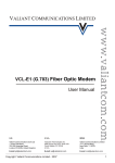
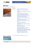
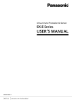
1
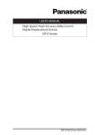
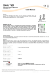
٨ Never use this product as a sensing device for personnel protection. ٨ In case of using sensing devices for personnel protection, use products which meet standards, such as OSHA, ANSI or IEC etc., for personnel protection applicable in WARNING each region or country. 1 SPECIFICATIONS Type Model No. Normally closed Item (Note 1) Normally open Max. operation distance (Note 2) Stable sensing range (Note 2) Standard sensing object Supply voltage Current consumption Output Short-circuit protection Max. response frequency Operation indicator Protection Ambient temperature Ambient humidity Material Cable Weight (Note 4) Accessories Non-shielded type Shielded type Non-threaded type Threaded type Threaded type GX-3S GX-4S GX-5S GX-5M GX-8M GX-8ML GX-4SB GX-5SB GX-5MB GX-8MB GX-8MLB GX-3SB 0.8mmr15% 1mmr15% 0.8mmr15% 1mmr15% 2mmr15% 0 to 0.6mm 0 to 0.8mm 0 to 0.6mm 0 to 0.8mm 0 to 1.6mm Iron sheet 55t1mm Iron sheet 66t1mm Iron sheet 55t1mm Iron sheet 88t1mm Iron sheet 1212t1mm 12 to 24V DCr10% 10 to 30V DC 12 to 24V DCr10% 10 to 30V DC Ripple P-P 10% or less Ripple P-P 10% or less Ripple P-P 10% or less Ripple P-P 10% or less 15mA or less <GX-5Sš, GX-8Mš, GX-8MLš> <GX-3Sš, GX-4Sš, GX-5Mš> NPN open-collector transistor NPN open-collector transistor Maximum sink current: 200mA (Note 3) Maximum sink current: 50mA Applied voltage: 30V DC or less (between output and 0V) Applied voltage: 30V DC or less (between output and 0V) Residual voltage: 1.5V or less (at 200mA sink current) Residual voltage: 0.4V or less (at 50mA sink current) 0.4V or less (at 50mA sink current) 㧙 Incorporated 㧙 Incorporated 1kHz 1.5kHz 1kHz 500Hz Red LED (lights up when the output is ON) IP67 (IEC) -25 to +70͠, Storage: -25 to +80͠ 35 to 85% RH 35 to 95% RH 35 to 95% RH, Storage: 35 to 95% RH 35 to 85% RH, Storage: 35 to 95% RH Storage: 35 to 95% RH Storage: 35 to 95% RH Enclosure: Brass Enclosure: Brass Enclosure: Brass (Nickel plated) Enclosure: Stainless steel (SUS304) (Nickel plated) (Nickel plated) Resin part: ABS Resin part: TPX Resin part: ABS Resin part: TPX 0.08mm2 3-core oil, heat and cold resistant cabtyre cable, 3m long 30g approx. MS-SS3 (Sensor mounting bracket): 1 pc. 㧙 MS-SS3-2 (C bracket): 1 pc. 0.14mm2 3-core oil, 0.08mm2 3-core oil, heat and cold resistant heat and cold resistant cabtyre cable, 3m long cabtyre cable, 3m long 55g approx. 30g approx. MS-SS5 (Sensor mounting bracket): 1 pc. 0.14mm2 3-core oil, heat and cold resistant cabtyre cable, 3m long 60g approx. Nut: 2 pcs., Toothed lock washer: 1 pc. Notes: 1) The model No. with '-R' stands for the flexible cable type. (e.g.) As for the flexible cable type of GX-3SB 'GX-3SB-R' The model No. with suffix '-C5' stands for the 5m cable length type. (e.g.) As for the 5m cable length type of GX-3SB 'GX-3SB-C5' 2) The maximum operation distance stands for the maximum distance for which the sensor can detect the standard sensing object. The stable sensing range stands for the sensing range for which the sensor can stably detect the standard sensing object even if there is an ambient temperature drift and/or supply voltage fluctuation. 3) The maximum sink current varies depending on the ambient temperature. Refer to ' 3 I/O CIRCUIT DIAGRAMS'. 4) The weight of the threaded type includes the weight of two nuts and one toothed lock washer. Sensor circuit GX Series Color code D (Brown) +V ZD (Black) Output (Note) Load Tr 50mA max. (Blue) 0V Internal circuit Users' circuit 12 to 24V DC r10% Note: GX-3Sغ, GX-4S غand GX-5M غdo not incorporate a shortcircuit protection at the output. Do not connect them directly to a power supply or a capacitive load. ٨ GX-5Sغ, GX-8Mغ, GX-8MLغ Color code D (Brown) +V (Black) Output Tr ZD Load 200mA max.(Note) (Blue) 0V Internal circuit + 10 to 30V DC - Users' circuit Symbols...D : Reverse supply polarity protection diode ZD : Surge absorption zener diode Tr : NPN output transistor Note: The maximum sink current varies depending on the ambient temperature. 200 100 0 -25 +55 Ambient temperature (͠) +70 If a capacitor of 1ǴF or more is connected between 0V and output or between +V and output, connect a 100ǡ resistor in series as shown below. Without the resistor, the short-circuit protection is activated by the change or discharge current of the capacitor, so that it results in delaying the response whenever the sensor switches. The connected resistor solves this problem. (Brown) +V (Black) Output 100ǡ (Blue) 0V Internal circuit +V 1ǴF or more Signal 1ǴF or more Users' circuit 2 CAUTIONS ٨ Make sure that the power supply is off while wiring. ٨ Take care that wrong wiring will damage the sensor. ٨ Verify that the supply voltage variation is within the rating. ٨ If power is supplied from a commercial switching regulator, ensure that the frame ground (F.G.) terminal of the power supply is connected to an actual ground. ٨ In case noise generating equipment (switching regulator, inverter motor, etc.) is used in the vicinity of this product, connect the frame ground (F.G.) terminal of the equipment to an actual ground. ٨ Do not run the wires together with high-voltage lines or power lines or put them in the same raceway. This can cause malfunction due to induction. ٨ Extension up to total 100m is possible with a 0.3mm2, or more (GX-8MLغ: 0.14mm2, or more), cable. + - Symbols...D : Reverse supply polarity protection diode ZD : Surge absorption zener diode Tr : NPN output transistor Sensor circuit Inductive Proximity Sensor Small 3 I/O CIRCUIT DIAGRAMS ٨ GX-3Sغ, GX-4Sغ, GX-5Mغ Max. sink current (mA) INSTRUCTION MANUAL Thank you very much for using SUNX products. Please read this Instruction Manual carefully and thoroughly for the correct and optimum use of this product. Kindly keep this manual in a convenient place for quick reference. ٨ Do not use during the initial transient time (10ms) after the power supply is switched on. ٨ GX-3Sغ, GX-4S غand GX-5M غdo not incorporate a short-circuit protection at the output. ٨ Do not connect them directly to a power supply or a capacitive load. ٨ Take care that the sensor does not come in direct contact with water, oil, grease, organic solvents, such as, thinner etc., or strong acid, and alkaline. ٨ Make sure that the sensing end is not covered with metal dust, scrap or spatter. It will result in malfunction. ٨ Make sure that stress by forcible bend or pulling is not applied directly to the sensor cable joint. ٨ Since the cable end is not waterproof, do not use the sensor in the application where water may seep in from the cable end. Phone: 800.894.0412 - Fax: 888.723.4773 - Web: www.clrwtr.com - Email: [email protected] 0V When mounting the sensor, if tightening torque exceeding the soecified is applued, the sensor may be damaged. ٨ The tightening torque should be under the value given below. Mounting with a set screw <Shielded threaded type> ٨ Tighten the set screw on the flat surface of the sensor without applying excessive force. Make sure to use a set screw with a cup-point end. Set screw (M4 or less) (Note) A Note: To fasten GX-5Mغ, use a M3 or less set screw. Model No. GX-5Mغ GX-8Mغ Set screw tightening position A (mm) 5 to 10 8 to 22 Tightening torque 0.29N㨯m 0.29N㨯m <Non-threaded type and non-shielded threaded type> Set screw (M4) B B (mm) C (mm) 5 to 10 3 5 to 10 8 to 20 13 to 22 3 5 10 Model No. GX-3Sغ When using the C bracket GX-4Sغ GX-5Sغ GX-8MLغ C Tightening torque 0.29N㨯m ٨ Distance from surrounding metal As metal around the sensor may affect the sensing performance, pay attention to the following points. Influence of surrounding metal The surrounding metal will affect the sensing performance. Keep the minimum distance specified in the table below. Background metal 4 MOUNTING E Embedding of the sensor in metal 0.58N㨯m 0.58N㨯m 0.29N㨯m 0.29N㨯m ٨ To fasten GX-3S غand GX-4Sغ, use a M3 or less set screw and tighten it from a direction perpendicular to the operation indicator. Good No good Operation indicator Operation indicator Set screw Model No. GX-3Sغ GX-4Sغ GX-5Sغ GX-8MLغ F G Metal ٨ When using the C bracket, place it on the sensor at a distance of 3mm or more from the sensor end. H Parallel mounting C bracket J 3mm or more ٨ To fasten the non-shielded threaded type, tighten the set screw on the flat surface on the sensor. Mounting with nut Mount such that the nuts do not protrude from the threaded portion. <Shielded threaded type> <Non-shielded threaded type> D Mounting plate Attached toothed lock washer (2 pcs. attached for '-R' type only) Model No. GX-5Mغ GX-8Mغ GX-8MLغ Dimension D 2 to 3mm 3mm or more 3 to 11mm 11mm or more 9 to 11mm 11mm or more Attached toothed lock washer Mounting plate F (mm) Ǿ12 Ǿ12 Ǿ15.4 Ǿ30 G (mm) 3 3 5 10 ٨ Mutual interference When two or more sensors are installed in parallel or face to face, keep the minimum separation distance specified below to avoid mutual interference. Face to face mounting D E (mm) 3 3 4 3 4 8 Sensing range may decrease if the sensor is completely embedded in metal. Especially for the non-threaded type and the non-shielded type, keep the minimum distance specified in the table below. Note: Mount such that the nuts do not protrude from the threaded position. Operation indicator Model No. GX-3Sغ GX-4Sغ GX-5Sغ GX-5Mغ GX-8Mغ GX-8MLغ Model No. GX-3Sغ GX-4Sغ GX-5Sغ GX-5Mغ GX-8Mغ GX-8MLغ H (mm) 16 16 20 10 20 50 J (mm) 16 16 15 10 15 30 ٨ Sensing range The sensing range is specified for the standard sensing object. With a non-ferrous metal, the sensing range is obtained by multiplying with the correction coefficient specified below. Correction coefficient Model No. Metal Iron Stainless steel (SUS304) Brass Aluminum 1 GX-5Sغ GX-8Mغ GX-8MLغ 1 0.65 approx. 0.70 approx. 0.83 approx. 0.36 approx. 0.30 approx. 0.40 approx. 0.35 approx. 0.61 approx. 0.58 approx. GX-3Sغ GX-4Sغ GX-5Mغ 1 Note: The sensing range also changes if the sensing object is plated. Tightening torque 0.49N㨯m 1.47N㨯m 1.47N㨯m 3.43N㨯m 0.98N㨯m 3.43N㨯m Note: Mount such that the nuts do not protrude from the threaded portion. ٨ Caution with GX-8M غand GX-8MLغ The root truncation of the threads is shallow owing to strengthening of the sensors against tightening. When tapping holes on equipment to fix the sensors, the prepared holes must be Ǿ7.2mm or more with GX-8M غand GX-8MLغ Tapping holes Sensor Limited SUNX Head Office 2431-1 Ushiyama-cho, Kasugai-shi, Aichi, 486-0901, Japan Phone: +81-(0)568-33-7211 FAX: +81-(0)568-33-2631 Overseas Sales Dept. Phone: +81-(0)568-33-7861 FAX: +81-(0)568-33-8591 PRINTED IN JAPAN Phone: 800.894.0412 - Fax: 888.723.4773 - Web: www.clrwtr.com - Email: [email protected]