1
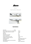
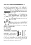
Continuum Audio Laboratories – Copperhead Installation and Owners Manual
TABLE OF CONTENTS
IMPORTANT INFORMATION AND NOTES................................................................................... 5
WHO SHOULD READ THIS MANUAL ........................................................................................... 5
HOW TO READ THIS MANUAL ...................................................................................................... 5
STANDARD SYMBOLS AND SAFETY NOTIFICATIONS ............................................................. 5
SAFETY PRECAUTIONS .................................................................................................................. 6
PACKAGING .................................................................................................................................. 7
COPPERHEAD TONEARM ............................................................................................................... 8
SPECIFICATIONS ................................................................................................................................ 9
FEATURES ........................................................................................................................................... 10
THE ARM WAND ......................................................................................................................... 10
THE HEADSHELL........................................................................................................................ 10
AZIMUTH STABILIZED BEARING SYSTEM .............................................................................. 10
ADJUSTABLE AZIMUTH............................................................................................................. 10
ADJUSTABLE VTA ....................................................................................................................... 10
LOW MASS PIVOT DESIGN. ....................................................................................................... 10
ULTRA RIGID CENTRAL TOWER .............................................................................................. 10
PRECISION GRADUATED RADIAL VTA VERNIER GAUGE .................................................... 11
LARGE SCALE CARTRIDGE WEIGHT ADJUSTMENT ............................................................. 11
SMALL SCALE CARTRIDGE WEIGHT ADJUSTMENT ............................................................. 11
THE FINGERLIFT........................................................................................................................ 11
THE HYDRAULIC ARM LIFTER ................................................................................................. 11
THE COUNTERWEIGHT ............................................................................................................. 11
THE VERTICAL BEARING MOTION .......................................................................................... 12
HORIZONTAL MOTION SUPPORT ............................................................................................ 12
VERTICAL TRACKING ANGLE (VTA) AND STYLUS RACK ANGLE (SRA) ............................. 12
OVERHANG ADJUSTMENT ........................................................................................................ 14
ANTI SKATE ADJUSTMENT ....................................................................................................... 14
INSTALLATION & SETUP ............................................................................................................... 15
WHY CARTRIDGE SETUP AND ALIGNMENT IS CRITICAL .................................................... 15
INSTALLATION .............................................................................................................................. 17
COPPERHEAD COMPONENTS.................................................................................................. 18
DISASSEMBLY FOR MOUNTING PROCEDURE ...................................................................... 20
TONEARM PIVOT TO RECORD SPINDLE DISTANCE ............................................................. 21
MOUNTING THE MAIN ARM BASE TO THE ARMBOARD ...................................................... 22
MOUNTING THE MAIN ARM TOWER TO THE MAIN ARM BASE .......................................... 23
VTA (SRA) SETUP HOW TO ADJUST VTA (SRA) ....................................................................... 24
COPPERHEAD ARMWAND LAYOUT .......................................................................................... 25
MAIN WAND ASSEMBLY - UNDERSIDE ................................................................................... 25
MAIN WAND ASSEMBLY – TOP SIDE ....................................................................................... 26
HOW TO MOUNT THE ARMWAND ........................................................................................... 27
SKEWING THE REAR MAIN “HEART” SHAPED COUNTERWEIGHT ................................... 29
BALANCING THE ARMWAND .................................................................................................... 30
CARTRIDGE WEIGHT & BALANCE TABLE .............................................................................. 32
COPPERHEAD COUNTERWEIGHT “WASHER” KIT .............................................................. 33
EXAMPLE: BALANCING A 15 GRAM CARTRIDGE .................................................................. 33
INSTALLING CARTRIDGE ON WAND ....................................................................................... 35
OVERHANG FINE ADJUSTMENT AND VTF CHECK ............................................................... 36
HOW TO CONNECT AND ADJUST THE ANTISKATE .............................................................. 37
GROOMING THE TONEARM WIRE ........................................................................................... 39
HOW TO ADJUST THE AZIMUTH ............................................................................................. 40
AZIMUTH ADJUSTMENT M3 SET SCREW ................................................................................ 41
ADJUSTING ARMLIFTER HEIGHT ............................................................................................ 42
ADJUSTING ARMLIFTER ROTATION ....................................................................................... 43
INSTALLING OR REMOVING ARMLIFTER ............................................................................... 44
Written By: MDO
Approved By: LPO
Revision A
Page 2 of 48
Continuum Audio Laboratories – Copperhead Installation and Owners Manual
SECURING THE ARM WIRE CABLE CLAMP OR TERMINATION BLOCK ............................. 45
OPERATION OF THE ARM ............................................................................................................. 46
OWNER CARE & MAINTENANCE ................................................................................................ 46
CARING FOR METAL SURFACES.............................................................................................. 46
CLEANING THE TONEARM ....................................................................................................... 46
BEARING MAINTENANCE .......................................................................................................... 46
COPPERHEAD’S DESIGN HISTORY ............................................................................................ 47
COPPERHEAD’S DESIGN TEAM ................................................................................................... 48
Written By: MDO
Approved By: LPO
Revision A
Page 3 of 48
Continuum Audio Laboratories – Copperhead Installation and Owners Manual
Welcome and congratulations on your purchase of our Copperhead Tonearm. Your
Copperhead was hand-crafted and assembled by the team at Continuum Audio Labs, and has
been rigorously tested and is ready for your enjoyment.
The Copperhead is a new design in tonearm technology which has been developed by a team
of dedicated music lovers with qualifications in advanced engineering and design, assisted by
some of the most advanced computer aided design software in the market today.
We ask that you take the time to read this manual carefully to ensure that you not only enjoy
optimum sound quality from your Copperhead, but also understand the care and maintenance
procedures required to keep your Copperhead in as-new condition for many years to come.
If you have any questions in reference to any part of your Copperhead at any time in the
future, please feel free to contact your nearest Continuum Consultant for assistance.
Congratulations on choosing the Copperhead tonearm.
Your Authorised Continuum Consultant is:
Serial Number:
Date of Manufacture:
Written By: MDO
Approved By: LPO
Revision A
Page 4 of 48
Continuum Audio Laboratories – Copperhead Installation and Owners Manual
IMPORTANT INFORMATION AND NOTES
ENGLISH
WE RECOMMEND YOU READ THIS DOCUMENT IN ITS ENTIRETY
BEFORE ATTEMPTING TO ASSEMBLE OR DISASSEMBLE YOUR NEW
TONEARM.
NOTE: Improvements may result in specification or feature changes
without notice. Illustrations may differ slightly for production models.
WHO SHOULD READ THIS MANUAL
This manual is designed for the installer and owner operator of the Copperhead tonearm.
HOW TO READ THIS MANUAL
The User manual (this manual) contains important notes that need to be observed to operate
the Copperhead safely and correctly.
Before using the Copperhead, please read and thoroughly understand the contents of this
manual. Keep this manual in a safe location.
Throughout this manual there will be standard symbols denoting important
information.
If you have any questions in reference to any part of your Copperhead at any time in the
future, please feel free to contact us or your Consultant for assistance.
STANDARD SYMBOLS AND SAFETY NOTIFICATIONS
For your safety and that of others, follow the guidelines provided on the following pages
concerning the use of the product.
Symbols are used throughout this manual. These are provided to emphasize important points
for your safety and that of others. The following are the symbols and their meanings:
CAUTION
Ignoring the instructions under this symbol when using the Copperhead may
lead to damage to the device or hardware options.
Written By: MDO
Approved By: LPO
Revision A
Page 5 of 48
Continuum Audio Laboratories – Copperhead Installation and Owners Manual
SAFETY PRECAUTIONS
Category
Installation
CAUTION
Do not dismantle or modify this device in any other way than
described in this manual.
Do not place anything on top of this device. Doing so may
cause a malfunction.
Do not install this device in direct sunlight, near a heater, or in
a humid or dusty environment. Do not expose this unit to rain
or moisture. Do not use or allow any liquid cleaning solutions to
enter the unit.
The components in the Copperhead are made to close
tolerances with sliding fits on most bearing surfaces. Never
over-tighten any of the provided fasteners. If you are in doubt
request the assistance of a trained dealer representative to
ensure no forcing or misalignment of the components during
assembly.
Before connecting to phono stage components, be sure to
follow component manufacturer’s instructions.
Clean tonearm, and controls with a soft cloth slightly moistened
with a mild detergent solution. Do not use any type of abrasive
pad, scouring powder or solvent such as alcohol or benzene.
Written By: MDO
Approved By: LPO
Revision A
Page 6 of 48
Continuum Audio Laboratories – Copperhead Installation and Owners Manual
PACKAGING
Please retain all the packaging in a safe dry place away from fire hazard and/or pests which
could damage the packaging materials. We highly recommend you retain the packaging your
Copperhead came in, so that if at any point in the future you need to move your Copperhead,
it can be done safely.
Never transport the tonearm assembled as this will potentially lead to serious damage to the
bearing.
THERE ARE 5 MAIN COMPONENTS WHICH COMPRISE THE COPPERHEAD TONEARM SYSTEM
1
2
3
4
5
–
–
–
–
–
Wand Assembly
Tonearm Base, Bearing and Anti-Skate
Wiring Harness
Cartridge Screws
Counterweight Washer Kit & Screws
Written By: MDO
Approved By: LPO
Revision A
Page 7 of 48
Continuum Audio Laboratories – Copperhead Installation and Owners Manual
COPPERHEAD TONEARM
The Copperhead Tonearm is named after a rare highly venomous Australian snake
found in the higher reaches of the Victorian Alps. Altitude is no bar to the
Copperhead.
Derived with the same ultra advanced software and technology Continuum Audio
Laboratories pioneered to design and build the Cobra tonearm (Winner of Stereophile
Analog Product of the Year 2006 award and Product of the Year Award 2006) the
Copperhead is another groundbreaking product destined to become a favourite with
discerning audiophiles.
The Copperhead design is very musical but remains uncoloured by spurious
resonances. Continuum Audio Laboratories are the leader in using advanced software
to develop a close correlation between the modelled behaviour of an arm and the
actual real world performance. This allows our engineers to derive new solutions to
previously unsolved problems.
Our engineers again applied the complete suite of advanced software available to
Continuum Audio Laboratories towards the modelling of the Copperhead arm.
Beginning with Finite Element Analysis using NASTRAN, PATRAN, and DYTRAN
from www.mscsoftware.com finalizing in the complex process of Gradient Shape
Optimisation using Reshape™ from www.advea.com.
The final Copperhead shape emerged from this process as a refined sleek shape which
maintained the “signature” free sound of the Cobra design. The wand is eggshell thin
with special contours and compound curves to “shape” the resonant behaviour of the
arm. These behaviours are only visible with specialized software tools but clearly
audible to experienced listeners. Designing with these tools allows us to bring arm
design into the 21st century.
This breakthrough in arm engineering ensures the shape of the wand improves the
sound of the arm beyond that which is possible using conventional tube designs.
No other competitively priced arm comes close to the sonic reality of the Copperhead.
Written By: MDO
Approved By: LPO
Revision A
Page 8 of 48
Continuum Audio Laboratories – Copperhead Installation and Owners Manual
SPECIFICATIONS
• Effective Length: (from stylus to pivot point) 239mm
• Overhang: (from Stylus to spindle Centre) 17.3mm
• Offset: (Headshell Offset in degrees) 23 Degrees
• Cartridge Fixing Centres: 12.7mm for standard M2.5 socket head cap screws
• Mounting Distance: (from pivot to spindle centre) 221.7mm
• Arm Mount Hole Pitch: 76mm by 4 equidistant cardinal points for 4mm metric socket
head cap screws.
• Depth Below mounting surface: 40-50mm.
• Radial Clearance for Counterweight: 90mm
• Clearance from plinth surface to top of arm mount: 150mm preferred for arm wire
training.
• Cartridge Weight Range: 0-20Grams – Adjusted by Mass Addition/Subtraction of
Supplied Weight Adjustment Kit. Fine tuned by 8 Gram sliding set screw for 0.001 Gram
adjustment increments.
• VTA Adjust: – Yes
• Azimuth Adjust: - Yes
• Horizontal Natural Frequency: 7-10Hz depending on suitable cartridge
• Vertical Natural Frequency: 7-10Hz depending on suitable cartridge
• NULL POINTS: 66.0mm Inner 120.8mm Outer
• Audio Lead: Supplied with Continuum Audio Labs “six-nines” Copper as 1.5 meter
standard in our preferred configuration of single RCA Termination from Cartridge Clip to
RCA Male Connector.
Other Arm leads are available and can be supplied on request.
Other arm wires on request.
• DIN Plugs: can be fitted as an optional extra.
• Complete Arm Weight: 0.5Kg Nominal
Written By: MDO
Approved By: LPO
Revision A
Page 9 of 48
Continuum Audio Laboratories – Copperhead Installation and Owners Manual
FEATURES
The Copperhead represents a major breakthrough in tonearm technology. By the use of
advanced software design tools which, for the first time, allowed us to simulate the real-time
dynamics of a tonearm in play; we could visualize the flexural and vibrational issues inherent
in all tonearms. This allowed us to create the unique Copperhead shape which overcomes
these limitations.
THE ARM WAND
Reshape™ Shape Optimised, Resonance Tuned Compound Curve Wand from proprietary
woven fibre technology pioneered by Continuum Audio Laboratories. Wands are
interchangeable allowing you to easily interchange arm wands for quick cartridge
changeovers (i.e Stereo to Mono).
The Copperhead is unique monocoque construction using advanced fibre and resin technology
proprietary to Continuum Audio Labs. The shape of the arm wand is optimised to reduce the
resonances inherent in conventional tonearm mechanisms. The Copperhead’s polymer/fibre
technology is extremely well damped and overcomes the limitations found in other materials
used in tonearm manufacturer.
THE HEADSHELL
The Copperhead headshell is an integrated part of the arm wand and has standard slots for
M2.5 cartridge screws. The use of compound curves make the head of the arm very
resistant to torsional vibration modes created by the stylus groove interaction.
AZIMUTH STABILIZED BEARING SYSTEM
The Sapphire Ring Swash plate rides on damped ABEC9 miniature precision bearings to
stabilize the arm azimuth. (Also found in the Copperhead tonearm system)
Primary Radial and Vertical Pivot is on a primary Sapphire Vee Jewel bearing with
hardened stainless pivot.
ADJUSTABLE AZIMUTH
Azimuth is adjustable by means of set screw located adjacent to main pivot.
ADJUSTABLE VTA
Copperhead uses a 25mm central tower with a 40TPI (threads per inch) Microscope Thread
for ultra fine VTA adjustment. Every 4mm of vertical adjustment at the rear of the
tonearm will equal 1 degree of change at the stylus tip. Even micro adjustments of 1 arc
minute at the rear of the arm will be audible to experienced audiophiles.
LOW MASS PIVOT DESIGN.
No additional mass is placed over the pivot to improve the responsiveness of the bearing
system. The Copperhead is free of the inertial energy storage found in high mass bearing
systems.
ULTRA RIGID CENTRAL TOWER
Located in a precision machined mounting collar with integrated locking collar, this locking
collar spreads the clamping load on the adjustable VTA shaft and prevents movement
when locked. No point loads.
Written By: MDO
Approved By: LPO
Revision A
Page 10 of 48
Continuum Audio Laboratories – Copperhead Installation and Owners Manual
PRECISION GRADUATED RADIAL VTA VERNIER GAUGE
Allows for repeat VTA setting accurate to 1 arc minute (360 degree graduation). 4 mm
adjustment at rear pivot equals 1 degree of Stylus Rake Angle adjustment. A
complimentary VTA Vertical Scale Vernier allows for broad range calibration.
LARGE SCALE CARTRIDGE WEIGHT ADJUSTMENT
By a simple addition/subtraction method with supplied washer kit this maintains the
designed optimum effective mass relationship with a broad range of cartridges.
SMALL SCALE CARTRIDGE WEIGHT ADJUSTMENT
By a precision set screw at the rear of the arm the ultra fine adjustment allows for +- 0.5
Grams in 0.001gram increments
THE FINGERLIFT
The Copperhead finger lift is extended to the right of the head shell at an angle designed to
allow safe cueing.
It is recommended that one use extreme caution when cueing manually as stylus damage can
result from minor errors in handling. We recommend use of the hydraulic arm lifter to ensure
safe operation of cartridge cueing.
THE HYDRAULIC ARM LIFTER
The hydraulic arm lift is an standard industry format using silicon gel damping. The height of
the hydraulic arm lifter is adjustable using a standard metric allen wrench.
THE COUNTERWEIGHT
The Copperhead uses a unique counter-weight design that ensures the tracking force remains
constant regardless of VTA adjustment.
The neutral balance has been achieved by locating the arm pivot system at the level of the
record and locating the centre of mass at the height of the record.
In addition, to minimize warp wow (pitch changes as the stylus rides up and down over record
warps), the arm’s vertical pivot should be at the same height as the record surface. The
Copperhead uses a shape optimized counterweight for reduction of reflected vibration.
Written By: MDO
Approved By: LPO
Revision A
Page 11 of 48
Continuum Audio Laboratories – Copperhead Installation and Owners Manual
THE VERTICAL BEARING MOTION
The Primary Pivot is a precision sapphire vee jewel with hardened steel matching central pivot.
Used in the finest of aircraft instruments this pivot technology does not require heavy mass to
be positioned over the pivot, thus allowing for exceptional tracking and response to groove
modulation.
Secondary Pivot provides horizontal stabilisation and azimuth alignment with a hardened steel
inverted pivot resting on a man made sapphire “Swash Plate”.
This secondary pivot plays a crucial role in the stability of the arm allowing for optimum
placement of the counterweight thus removing inertial problems associated with alternative
stabiliser designs.
HORIZONTAL MOTION SUPPORT
The Copperhead uses two precision matched ABEC 7 vertically opposed bearings with internal
damping are used to minimise resistance in the circular motion for the secondary pivot.
VERTICAL TRACKING ANGLE (VTA) AND STYLUS RACK ANGLE
(SRA)
Continuum Audio Labs recognizes that the original cutting lathes used to make the master
recordings have different orientation of the cutter to the surface of the original lacquer.
Therefore, during playback even minor changes in SRA or VTA can have significant audible
effects.
The Copperhead offers the discerning audiophile an easy to adjust mechanism to extract the
last vestiges of performance from your favourite LP. To adjust the VTA, two screws located on
the base of the main arm mount are gently loosened to free the main arm tower
The user turns the VTA fine vertical adjustment knob clockwise to raise the arm pivot and
counter-clockwise to lower the arm pivot.
Once the desired setting is reached the screws are gently tightened to lock the arm mechanism
precisely in place. This system prevents any grub screw marking of the main sliding shaft
system. This is adjustable during playback to dial-in your favourite setting for various thickness
of LP’s.
A broad scale vertical Vernier indicator is located on the rear of the main arm support tower
which is further enhanced by a fine scale micrometer dial on the adjustment knob located at
the top of the main arm support tower.
A vertical movement of 4mm in the main arm pivot represents 1 degree of VTA (SRA) change.
The Copperhead arm is very revealing of setup errors so will require the best possible
alignment in the horizontal and vertical plane.
It is advisable to follow the cartridge manufacturer’s recommendations to ensure the top of the
cartridge mounting surface is parallel to the surface of the record.
The Copperhead arm requires a dedicated tool to set the cartridge mounting surface parallel to
the record surface.
Written By: MDO
Approved By: LPO
Revision A
Page 12 of 48
Continuum Audio Laboratories – Copperhead Installation and Owners Manual
As a general rule if the VTA is too high the sound will be “lean and thin”, and if the VTA is too
low the sound will be more bass heavy and exhibit less transparence. This is of course totally
to user preference.
Written By: MDO
Approved By: LPO
Revision A
Page 13 of 48
Continuum Audio Laboratories – Copperhead Installation and Owners Manual
OVERHANG ADJUSTMENT
The nominal effective length (stylus tip to main arm pivot) is 239mm. The length of slots in
the headshell allows +- 6mm from nominal effective length. This allows the majority of
cartridges to be properly mounted.
For the above effective length, the overhang based on Baerwald alignment should be 17.3mm
and 17.8mm for Lofgrin. The main arm pivot to platter spindle distance should be 221.7mm.
ANTI SKATE ADJUSTMENT
The Copperhead is equipped with an anti-skate device which provides optimal anti-skate force
for most records.
It is geometrically designed to increase the anti-skate force, as a percentage of the tracking
force (from 8% of the tracking force at the start of the record to 12% of the tracking force at
the end of the record).
The Arm wire guide is designed to minimise torque forces emanating from the arm wires
affecting the horizontal motion of the arm.
We recommend a quality tool such as “Wally Skater” from WAM Engineering, available from
reputable LP suppliers, is used to set anti-skate parameters.
CAUTION: In our opinion use of a grooveless vinyl surface to determine anti-skate
adjustment is an inaccurate method.
Written By: MDO
Approved By: LPO
Revision A
Page 14 of 48
Continuum Audio Laboratories – Copperhead Installation and Owners Manual
INSTALLATION & SETUP
WHY CARTRIDGE SETUP AND ALIGNMENT IS CRITICAL
If a phono cartridge is not correctly setup, damage can occur to your precious record
collection, and you will not experience the incredible realism that a good analogue system
can reproduce.
The design of the Copperhead tonearm allows for minute adjustments to be made to
ensure the stylus tip is correctly positioned in all planes.
The stylus tip traces the musical signal inscribed in the record groove, which can contain
modulations as small as a millionth of an inch. Therefore, small adjustments to the stylus
tip’s position will alter the sound significantly.
Good tonearm designs allow for precision adjustment in 4 main areas.
1.
2.
3.
4.
Tracking Angle
Azimuth Angle
Vertical tracking Angle (VTA) or Stylus Rake Angle (SRA)
Overhang
Written By: MDO
Approved By: LPO
Revision A
Page 15 of 48
Continuum Audio Laboratories – Copperhead Installation and Owners Manual
CAUTION
On the internet there are many resources available for learning about cartridge setup.
However we urge caution in following some of the recommendations found on user groups
and bulletin boards. Some of these tips are not based on sound engineering principles, and
can damage your cartridge.
CAUTION
Do not connect any voltage or electrical meter directly to tonearm cables which are
connected to a cartridge. If you use the wrong type of meter you can destroy a
cartridge coil mechanism. If you are unsure of the equipment you are using to
adjust azimuth please contact your Authorised Continuum Consultant.
Please refer to manufacturer instructions in all cases before trying any “tweaks”. Failure to
consult manufacturer instructions can result in a voiding of any warranties or
responsibilities.
Written By: MDO
Approved By: LPO
Revision A
Page 16 of 48
Continuum Audio Laboratories – Copperhead Installation and Owners Manual
INSTALLATION
This Manual is for Factory Authorized Installers and technically proficient users who are
familiar with phono cartridges and tonearm installation terminology and concepts.
The main steps of installing the Copperhead are:
1. Disassembly to enable mounting to armboard.
2. Installation of the central tower mount.
3. Re-assembly of main arm components.
4. Adjustment of pivot height relative to platter height.
5. Weighing your cartridge
6. Selecting the Weighted Washers to match Cartridge Weight.
7. Installing Cartridge on Wand.
8. Attaching Cartridge clips
9. Installing Wand on pivot assembly.
10. Securing the Arm Cable to Turntable
11. Balancing the wand and setting tracking force.
12. Connecting anti-skate string.
13. Grooming the Tonearm Wire.
14. Adjusting of anti skate force.
15. Adjustment of azimuth for initial cartridge setup.
Written By: MDO
Approved By: LPO
Revision A
Page 17 of 48
Continuum Audio Laboratories – Copperhead Installation and Owners Manual
COPPERHEAD COMPONENTS
The Copperhead comes to you with the main components assembled, and needs to be
partially disassembled for installation.
Antiskate Lever
with adjustable weight
Armwire
Guide
VTA Minor Scale
Vernier Dial - 360
Degree Adjustment
Set Screws
For height
adjustment of
Arm Lifter
Arm Lifter
VTA Major Scale Post
VTA Locking
Collar
M4 VTA Locking Screws
Written By: MDO
Main Tower
40TPI
Thread for
VTA
Approved By: LPO
Main Arm Base
Revision A
Page 18 of 48
Continuum Audio Laboratories – Copperhead Installation and Owners Manual
Sapphire Azimuth
“Swash Plate” for 2nd
Pivot
Main Arm Pivot
Antiskate
String “Tie
off” points
Arm Plate for
Ancillaries
Written By: MDO
Approved By: LPO
Revision A
Page 19 of 48
Continuum Audio Laboratories – Copperhead Installation and Owners Manual
DISASSEMBLY FOR MOUNTING PROCEDURE
Use a suitable allen key to undo the 2 x M4 VTA locking screws which are used to tighten
the VTA Locking Collar on to the Main Arm Tower.
Slide the central Main Arm Tower off the main body
Main Arm
Tower
Undo M4
Screws Before
Sliding Main
Tower from
Main Arm
Base
Note: Alignment of
VTA Major Scale
Post with hole in
Arm Plate
Main Arm
Base
.
NOTE: take notice of how the central tower fits through the main arm mount, for
when you have to reassemble it. You are now ready to mount the Arm Mount to
the Armboard.
Written By: MDO
Approved By: LPO
Revision A
Page 20 of 48
Continuum Audio Laboratories – Copperhead Installation and Owners Manual
TONEARM PIVOT TO RECORD SPINDLE DISTANCE
PIVOT TO SPINDLE DISTANCE IS 221.7mm.
Using the supplied template mark out and drill holes in the armboard as shown below.
Note: This has been predrilled for Criterion users. We recommend you use 4mm Socket
Head Cap Screws and professionally drill and tap the plinth or armboard to allow the arm
to be bolted directly to the plinth. Note: Criterion Copperhead predrilled at the
factory.
Note: If the plinth requires a cutout to access a sub-chassis then the main arm mount
requires a 72-80mm hole to be cut to allow for clearance.
All dimensions are in METRIC i.e millimeters.
PCD for M4 Screws is 56mm
HOLE for ARMTOWER is 44mm diameter by minimum 50mm deep.
Written By: MDO
Approved By: LPO
Revision A
Page 21 of 48
Continuum Audio Laboratories – Copperhead Installation and Owners Manual
MOUNTING THE MAIN ARM BASE TO THE ARMBOARD
Position and screw the Main Arm Base into the armboard (or your turntables arm mounting
mechanism) using 4 off M4 x 16mm Socket Head Cap Screws.
VTA Major
Scale Post
Offset to the
right as shown.
Note the position of the VTA Major Scale Post is offset to the right of the platter.
Written By: MDO
Approved By: LPO
Revision A
Page 22 of 48
Continuum Audio Laboratories – Copperhead Installation and Owners Manual
MOUNTING THE MAIN ARM TOWER TO THE MAIN ARM BASE
Position and lower the Main Arm Tower into the Main Arm Base taking care to align the
VTA Major Scale Post into the Arm Plate.
Rotate the VTA Minor Scale Vernier clockwise (to raise) or counter-clockwise (to lower) the
Main Arm Pivot to sit level with the top surface of the LP on the platter. This is a basic
starting point for initial VTA and weight adjustments.
Tighten the two VTA Clamp M4 Locking Screws to lock the Main Arm Tower into the Main
Arm Base.
Antiskate Adjustable
Weight
AntiSkate Lever
Arm Lifter
Sapphire
Swash Plate
Main Arm Pivot
Main Arm
Tower
VTA Major Scale Post
correctly located in
Arm Plate.
VTA Minor
Scale Vernier
Dial
Main Arm Base Mount
Written By: MDO
Approved By: LPO
VTA Clamp M4
Locking Screws
Revision A
Page 23 of 48
Continuum Audio Laboratories – Copperhead Installation and Owners Manual
VTA (SRA) SETUP HOW TO ADJUST VTA (SRA)
At the front of the Main Arm Mount there are two M4 Socket head cap screws. These need
to be gently loosened in order for the Main Arm Tower to be raised or lowered using the
VTA Minor Scale Vernier Dial at the top of the main arm mount.
Rotate the VTA Minor Scale Vernier clockwise (to raise) or counter-clockwise (to lower) the
Main Arm Pivot to sit level with the top surface of the LP on the platter. This is a basic
starting point for initial VTA and weight adjustments.
For initial setup, use a ruler or straight-edge to sit on the platter and allow it to protrude
over the edge of the platter and rotate over the main arm pivot. Adjust the height of the
Main Arm Tower until the surface of the platter and the tip of the main arm pivot are in
line. There is a Major Scale Vernier Post on the right hand side of the Arm Plate. This is
complemented by a minor scale vernier at the top of the VTA Minor Scale adjustment ring.
Ruler or
Straightedge
resting on top
platter surface
Adjust this VTA
Minor Scale
Vernier Dial to
raise or lower the
main pivot to be
level with the top
platter surface
Main Pivot Height. This
should be level with top
platter surface as the initial
reference point for VTA.
Once you have completed the setup of the tonearm and cartridge you can readjust the
VTA to suit your musical tastes. Raising the VTA will tend to lean out the sound whereas
lowering the VTA will tend to accentuate bass response. Optimal settings vary from LP to
LP and also according to thickness of the LP. Careful experimentation is needed to find the
“sweet” spot.
Written By: MDO
Approved By: LPO
Revision A
Page 24 of 48
Continuum Audio Laboratories – Copperhead Installation and Owners Manual
COPPERHEAD ARMWAND LAYOUT
MAIN WAND ASSEMBLY - UNDERSIDE
Fingerlift
Cartridge Mounting Surface
Monocoque
Wand
Cartridge
Screw Slots
Antiskate
String Guide
Cam
Tonearm Wire
Entry
Secondary Pivot
for Azimuth
Main Tonearm
Pivot – Sapphire
Jewel in Titanium
Holder
Fingerlift Torsion
Control Screw
Written By: MDO
Approved By: LPO
Location for
Weights
“Heart” shaped
Counterweight
Revision A
Page 25 of 48
Continuum Audio Laboratories – Copperhead Installation and Owners Manual
MAIN WAND ASSEMBLY – TOP SIDE
Fingerlift
Armwire
Exit Point
6MM Fine Balance
+ -0.5gm
Counterweight
Screw
Cartridge Screw
Headshell Slots
Antiskate String
Guide
Azimuth Set Screw
Adjustment Point.
Use long 2.5MM
Allen Key to adjust.
Written By: MDO
Approved By: LPO
Revision A
“Heart” Shaped
Counterweight –
Can be twisted to “skew”
weight onto second pivot.
Page 26 of 48
Continuum Audio Laboratories – Copperhead Installation and Owners Manual
HOW TO MOUNT THE ARMWAND
The Copperhead is designed to sit on the main pivot and rely on gravity to keep it in place
during operation. The secondary pivot stabilizes the arm and allows for azimuth
adjustment.
A third anti-torsion screw is used to prevent “rocking” the arm when manually cueing the
arm using the finger lift. This helps protect the stylus.
Secondary Pivot for
Azimuth Adjustment.
M3 Threaded from top of
armwand. This locates
onto Sapphire Swash
Plate.
Antiskate String
Guide
Main Pivot – Sapphire
Jewel Vee bearing point.
This locates onto Main
Arm Tower central pivot
Anti-torsion screw for
Manual stylus cueing.
To mount the arm wand, gently place the armwand Main Sapphire Vee Jewel bearing cup
directly on to the center arm pivot on the main arm tower. Gently rock the arm back and
forth to confirm the jewel has seated correctly.
The tone arm is now held in place by gravity. There is no need to adjust any bearing
tension or slack.
Written By: MDO
Approved By: LPO
Revision A
Page 27 of 48
Continuum Audio Laboratories – Copperhead Installation and Owners Manual
6MM Fine
Adjustment Screw
Weight
Anti-Torsion Screw
Note: Gap between
Screw and Sapphire
Swash plate
Written By: MDO
Main Sapphire Vee
Jewel Pivot sitting
correctly on center
pivot of main arm
tower
Approved By: LPO
Revision A
Secondary Pivot for
Azimuth
Adjustment sitting
on Sapphire Swash
plate
Page 28 of 48
Continuum Audio Laboratories – Copperhead Installation and Owners Manual
SKEWING THE REAR MAIN “HEART” SHAPED COUNTERWEIGHT
The Copperhead Arm uses two pivots. The primary pivot for rotation and the secondary
pivot for azimuth control. To ensure the correct force is applied to the secondary azimuth
stabilising pivot the user can “skew” the “heart” shaped main counterweight slightly to the
right when viewed from above. Retighten the screw under the “heart” shaped weight to
lock the “skew” angle before inserting the “washer weights for final VTF.
Written By: MDO
Approved By: LPO
Revision A
Page 29 of 48
Continuum Audio Laboratories – Copperhead Installation and Owners Manual
BALANCING THE ARMWAND
Balancing any tonearm is a delicate operation requiring steady hands and a set of fine
scales, accurate to 0.01 of a gram or better. The Copperhead’s shape optimized counter
weight is a fixed distance from the arm pivot, but is fully adjustable by means of adding or
subtracting a series of precisely weighted “washers”.
Under the counter weight is a hollow section where “washers” of varying thickness can be
added or removed to balance the cartridge. These weights are used to establish the
tracking force close to optimum.
Final adjustment to precise tracking force is accomplished by winding the 6mm fine weight
adjustment screw at the rear of the arm. Winding in, increases tracking force, winding out
decreases the tracking force. In 0.001 gram increments a total of + or - 0.5 Grams is
possible with the 6MM Fine Weight Adjustment Screw.
6MM FINE WEIGHT
ADJUSTMENT
SCREW
Cartridge
position will
affect balance.
Hollow section for fixing weighted
washers in the underside of the “Heart
Shaped Main Counterweight”
Brass and Aluminium
Weighted “washers”
M4 Socket Head Cap Screw for
retaining weighted washers into
hollow section. Use different length
screw depending on amount of
washers
Balancing the armwand takes a little preparation but is straightforward as explained below.
Written By: MDO
Approved By: LPO
Revision A
Page 30 of 48
Continuum Audio Laboratories – Copperhead Installation and Owners Manual
The recommended steps are:
1.
2.
3.
4.
5.
6.
Weigh your cartridge before installing it on the arm. Record the weight on a piece
of paper.
Weigh the cartridge stylus protector and record this information on a piece of
paper (Note- Assumes the cartridge comes with a stylus protector. Some cartridge
manufacturers do not provide this feature, so this is optional)
Consult the Cartridge Weight & Balance Table below for selecting the amount of
weights you will use to get “into the zone” for final adjustment.
Install the suggested counterweight washers in the underside of the “Heart”
Shaped Counterweight.
Install the cartridge in the headshell
Test the VTF (Vertical Tracking Force) using a quality scale.
Written By: MDO
Approved By: LPO
Revision A
Page 31 of 48
Continuum Audio Laboratories – Copperhead Installation and Owners Manual
CARTRIDGE WEIGHT & BALANCE TABLE
CARTRIDGE WEIGHT & BALANCE TABLE
For Nominal Vertical Tracking Force (VTF) of 2 grams +/- 0.1 grams.
Note: With cartridge placed at close to center of the headshell slots
Your Cartridge Weight in Grams Counterweight required with M4 Bolt in Grams
5.0
5.5
6.0
6.5
7.0
7.5
8.0
8.5
9.0
9.5
10.0
10.5
11.0
11.5
12.0
12.5
13.0
13.5
14.0
14.5
15.0
15.5
16.0
16.5
17.0
17.5
18.0
18.5
19.0
19.5
20.0
Written By: MDO
7.7
10.2
11.5
12.8
15.4
16.8
17.9
20.3
21.9
23.8
26.0
27.4
29.5
31.4
32.8
34.4
36.3
37.6
40.0
41.8
43.6
45.2
47.1
48.7
50.8
52.4
54.2
55.5
57.9
60.2
63.4
Approved By: LPO
Revision A
Page 32 of 48
Continuum Audio Laboratories – Copperhead Installation and Owners Manual
COPPERHEAD COUNTERWEIGHT “WASHER” KIT
The Copperhead Counterweight kit comes supplied with a variety of brass and aluminium
weight “washers” with matching length M4 screws. Weights of each sized “washer” are
listed in the table below.
WEIGHTS
Brass Big (3MM)
Brass Mid + (2MM)
Brass Mid – (1.5MM)
Brass Small (1MM)
Aluminum Big (3.5MM)
Aluminum Mid + (2MM)
Aluminum Mid - (1.5MM)
Aluminum Small (1MM)
15.9
10.4
7.7
4.9
5.3 x 2
3.4
2.5 x 2
1.6
EXAMPLE: BALANCING A 15 GRAM CARTRIDGE
Example of balancing a 15 gram Cartridge placed at the center of the headshell slots.
1.
Lookup the Weight and Balance Table till you see the 15 Gram Cartridge weight in the
left most column.
2.
Read across to the right hand side of that row to see you need around 43.6 grams of
“washers” to add to the underside of the “heart shaped counterweight” which is fixed
to the arm.
Your Cartridge Weight in Grams
15.0
Counterweight required with M4 Bolt in Grams
43.6
3.
So you would need the following complement of weights to get close to optimum major
balance before using the 6MM Fine Adjustment Screw at the rear of the tonearm for
the final +- 0.5 gram adjustment range.
4.
Therefore select the following weighted “washers” and an M4 Screw which is long
enough to secure all the washers with about 3-4mm of spare thread. Note this screw
length alters depending on the amount of washers you use. A full complement of
screws is provided with the arm.
Weight Washers for 15 Gram Cartridge are:
1 off Brass Big (3MM)
1 off Brass Mid + (2MM)
1 off Brass Mid – (1.5MM)
1 off Brass Small (1MM)
1 off Aluminum Mid - (1.5MM)
1 off Aluminum Small (1MM)
Plus 1 off M4 Screw to hold washers
Total Weight for 15 Gram Cartridge
15.9
10.4
7.7
4.9
2.5
1.6
0.6
44
5.
Add these weights to the underside of the Heart Shaped Main Counterweight and
secure with appropriate length M4 Socket Head Cap Screw.
6.
Mount your cartridge in the middle of the cartridge screw slots in the headshell.
Written By: MDO
Approved By: LPO
Revision A
Page 33 of 48
Continuum Audio Laboratories – Copperhead Installation and Owners Manual
1.
Where possible use the
cartridge stylus
protector and leave it
on the cartridge whilst
setting initial VTF.
Weigh the protector
separately and factor
this additional weight to
any readings on the
scale. By subtracting
the weight of the
cartridge protector from
any reading you can
Written By: MDO
NOTE: Please ensure the tonearm wire is loose enough
not to interfere with the VTF. Tonearm wire should be
looped over the Tonearm Wire Guide and exited as close
to vertical over the main tonearm pivot.
Approved By: LPO
Revision A
Page 34 of 48
Continuum Audio Laboratories – Copperhead Installation and Owners Manual
INSTALLING CARTRIDGE ON WAND
CAUTION
We recommend the cartridge should be installed with the arm wand removed
from the pivot and placed on a soft cloth on top of the platter or other stable,
safe surface.
Ensure Cartridge Cantilever is protected during installation.
The Copperhead headshell is an integrated part of the arm wand and accepts all standard
12.7mm spacing between cartridge mounting screws. Mount cartridge in the headshell
according to the manufacturer’s instructions.
Try to position cartridge
screw holes in the
middle of the middle of
the slots as the starting
position for balance and
overhang adjustment.
Do not force or over torque the M2.5 screws. A light “nip” is all that is required.
Connect the cartridge pins to the arm wire following the cartridge manufacturer’s
instructions.
Do not force the tonearm wire pins or bend and twist the wire unnecessarily as this can
lead to wire breaking (requiring delicate resoldering).
Written By: MDO
Approved By: LPO
Revision A
Page 35 of 48
Continuum Audio Laboratories – Copperhead Installation and Owners Manual
OVERHANG FINE ADJUSTMENT AND VTF CHECK
Overhang is adjusted by positioning the cartridge stylus in relation to the tonearm pivot.
Your Copperhead should have been mounted correctly in a predrilled arm board which
places the tonearm pivot at the optimum distance from main arm pivot to tonearm spindle.
This distance is 221.7 mm when viewing the platter from above (Plan View).
Final overhang is set by moving the cartridge in the headshell slots according to the
recommended tracing template using either a Baerwald, Lofgrin or Stephenson alignment
to minimise tracking error.
You will need to recheck the Vertical Tracking Force (VTF) of the cartridge with any
repositioning of the cartridge in the headshell.
Use the 6MM Fine Adjustment Screw at the rear of the tonearm wand to make any minor
adjustments to the VTF.
If necessary add or subtract a weight washer under the heart shaped counterweight to get
back into the +- 0.5 gram weight range that is controlled by the 6MM Fine Adjustment
Screw.
Written By: MDO
Approved By: LPO
Revision A
Page 36 of 48
Continuum Audio Laboratories – Copperhead Installation and Owners Manual
HOW TO CONNECT AND ADJUST THE ANTISKATE
The Copperhead uses a specially designed geometry to alter the force of the anti-skate
across the surface of the record from 8% of the vertical tracking force at the start of the
record to 12% of the vertical tracking force at the end of the record.
The Copperhead Arm Wand has a triangular shaped anti-skate “cam” on the underside of
the arm, around the main bearing cup. You will notice a lightweight cord attached to this
cam. The end of the cord is threaded through a loop on the end of the anti-skate lever
and tied off with a small socket head cap screw.
Adjustable Weight on
Antiskate Lever
Antiskate Cam with String
Loop the Antiskate
String across the cam
under the tonearm and
through the hole in the
lever. Exit on the rear of
the lever and wrap
around the small M2.5
Screw. Adjust the length
to suit the operation of
the arc of the arm and
then tighten the screw
against the string to lock
it in place.
Trim off any excess with
a pair of scissors.
Once this cord is attached the bias can be adjusted by changing the position and the mass
of the weight on the end of the anti skate lever.
Gently loosen and slide this weight up the lever to reduce anti-skate force. Slide it down
the lever to increase anti-skate force. Factory settings are close to optimum, but if you
need to add further weight, undo the thumb screw completely and add one of the supplied
3mm broad washers as required. Do not over tighten as the mechanism is designed to be
very light to reduce inertia.
Written By: MDO
Approved By: LPO
Revision A
Page 37 of 48
Continuum Audio Laboratories – Copperhead Installation and Owners Manual
This part of the Lever should be close to level when
cartridge is sitting on innermost groove on the LP.
The arc this lever operates in should not interfere with
the side of the Copperhead wand at rest.
Adjust antiskate string length to ensure free operation
of the arm across the surface of the LP
Antiskate String
Anti-skate force should be adjusted according to a percentage of the tracking force. We
recommend the use of tools such as Wally Skater from WAM Engineering to set anti-skate.
If you are unable to adjust to the correct range, try adding or subtracting the small washer
weights from the lever. This is done by undoing the thumbscrew completely and adding or
subtracting the 12mm penny washers with a 3mm hole. These washers are supplied in
your arm kit. Please contact us if you require replacements.
Arm wires can play a significant part in anti-skate forces. That is why we have provided an
arm wire guide to “groom” the arm wire to minimize torque. Ensure the armwire is hooked
through the arm wire guide centre “hook” and held directly over the main arm pivot. The
arm wire exits right above the main pivot for this reason. The arm wires are also wound in
opposing directions to minimize twisting forces. This then allows the antiskate lever to
work at an optimum level.
Written By: MDO
Approved By: LPO
Revision A
Page 38 of 48
Continuum Audio Laboratories – Copperhead Installation and Owners Manual
GROOMING THE TONEARM WIRE
By routing the tonearm wire over the main pivot a significant reduction in skating torque
being affected by tonearm wire twisting tension can be achieved.
The Copperhead tonearm wire can be “groomed” by the use of the Armwire Guide which is
detachable from the holder.
Rotate and adjust the Armwire Guide to keep the exit of the tonearm wire as close as
possible to vertical after it leaves the wand exit point.
Groom the wire around the Armwire Guide by “looping” it around the guide. Ensure the
wire does not interfere with the operation of the wand or counterweight.
Tonearm Wire
(red) being routed
over the Armwire
guide and down
past the arm
mechanism
Push Armwire Guide into
small hole in the top of
the holder.
Note: adjust small joggle
on the base of the arm
wire guide to hold it in
place once inserted into
the holder
Written By: MDO
Holder
Approved By: LPO
Revision A
Page 39 of 48
Continuum Audio Laboratories – Copperhead Installation and Owners Manual
HOW TO ADJUST THE AZIMUTH
The optimum azimuth for stereo records should be based on the crosstalk between
channels. This is measured by comparing the output from the left channel signal and the
right channel signal using a specially cut Test Record available from quality suppliers of
LP’s. Examples of these LP’s are the CARDAS TEST RECORD, ORTOFON TEST RECORDS
etc.
Your goal for proper azimuth setting is to get the two crosstalk readings (in Decibels) to
equal each other. Cartridge manufacturers do not all install their coils in a perfect 90
degree relationship to each other, nor in a 45 degree relationship with the top of the
cartridge mounting surface. Therefore, there is no rule as to which direction you must tilt
the cartridge.
We recommend you use a professional azimuth alignment measuring device such as a
Fluke 89 Mk IV Multimeter with Decibel Function and a Test Record with Azimuth Tracks
(Left Channel only, Right Channel only). If you do not have this test equipment you can try
to get close by using your eye to look at the azimuth plane of the cartridge body and
approximate a level position by eye. Whilst not optimum it is possible to improve the
system performance by removing gross alignment errors.
WARNING: DO NOT ATTEMPT TO ADJUST THE AZIMUTH DURING PLAY AS
SERIOUS DAMAGE TO THE STYLUS COULD OCCUR.
Written By: MDO
Approved By: LPO
Revision A
Page 40 of 48
Continuum Audio Laboratories – Copperhead Installation and Owners Manual
AZIMUTH ADJUSTMENT M3 SET SCREW
The Copperhead uses two pivots to stabilise the arm in the vertical plane. The main arm
pivot is fixed. The secondary pivot is adjustable.
This secondary pivot can be raised or lowered by adjusting the small M3 Set Screw located
adjacent to the Main Tonearm Pivot against the sapphire “swash plate” that it sits on. By
raising or lowering this secondary pivot the stylus azimuth is adjusted.
The M3 Set Screw can be wound down (clockwise rotation when viewed from above) or
wound up (counter-clockwise when viewed from the top).
If you look at the arm from the front on you will see a secondary pivot adjacent to the
main arm pivot on the right. This is the secondary pivot that rests on the sapphire swash
plate.
Use a 1.5MM Allen Key and insert it into the top of the small hole next to the main pivot
towards the rear of the arm. You will feel the Allen key “engage” into the set screw. Raise
or lower this set screw to adjust the azimuth.
M3 Azimuth Adjustment Set
Screw is accessed via the small
hole adjacent to the main pivot.
Note: The screw is embedded in
the tonearm material and is self
locking. Turn clockwise to adjust
down, counterclockwise to adjust
up.
Written By: MDO
Approved By: LPO
Revision A
Page 41 of 48
Continuum Audio Laboratories – Copperhead Installation and Owners Manual
ADJUSTING ARMLIFTER HEIGHT
The Copperhead uses a compact hydraulic armlifter for safe cueing operation. The height
of this mechanism needs to be adjusted to ensure enough clearance for the LP both with
the arm lifted off the groove. Correspondingly when the cartridge is in the groove the
armlifter needs to retract leaving enough clearance for safe unimpeded operation of the
arm across the entire LP surface.
Adjust Armlifter by
loosening the M4 Set
Screws and sliding the
armlifter body up or
down to suit the
cartridge height and
enough space for LP
clearance.
Written By: MDO
Approved By: LPO
Revision A
M4 Set
Screws
Page 42 of 48
Continuum Audio Laboratories – Copperhead Installation and Owners Manual
ADJUSTING ARMLIFTER ROTATION
To ensure the Armlifter does not interfere with the Antiskate Lever rotate the top of the
armlifter as shown to allow for clearance. Note: You have to loosen the two M4 set screws
holding the height position of the armlifter and rotate the whole mechanism without losing
the height setting. .
Antiskate
Lever
Rotate the Armlifter to
ensure the Antiskate
Lever has free
operation with no
collision.
Written By: MDO
Approved By: LPO
Revision A
Page 43 of 48
Continuum Audio Laboratories – Copperhead Installation and Owners Manual
INSTALLING OR REMOVING ARMLIFTER
To install or remove the armlifter you have to remove the M2 Screw holding the armlift
from the hydraulic lifting mechanism and spacer as shown below.
Insert or remove the mechanism from the arm by means of the M2 Screw.
Remove or
install M2
Screw
Arm Lift
Spacer
Hydraulic
Lift
Mechanism
Anti-Rotation Pin>
Aligned with small
hole in top of
Hydraulic Lift
Mechanism
Small alignment
hole
Written By: MDO
Approved By: LPO
Copperhead Armlifter
Holder
Revision A
Page 44 of 48
Continuum Audio Laboratories – Copperhead Installation and Owners Manual
SECURING THE ARM WIRE CABLE CLAMP OR TERMINATION
BLOCK
To secure the Arm Cable use the Terminal Block supplied and mount it to the rear of the
Criterion Chassis (or other suitable place if using another turntable).
Cable Clamp Bolts
Loosen or remove
to access clamp.
Tighten once cable
installed
Route
Armwire
and clamp
here
M4
Safety
Screw
Written By: MDO
Approved By: LPO
Revision A
Page 45 of 48
Continuum Audio Laboratories – Copperhead Installation and Owners Manual
OPERATION OF THE ARM
The Copperhead tonearm is easy to operate once you have calibrated the Overhang,
Tracking Angle, Azimuth and VTF.
Use the Armlifter to raise the arm. Cue the record with the fingerlift. Lower the armwand
using the Armlifter and play LP.
Once the LP ends use the armlifter to raise the arm. Use the fingerlift to return the arm to
the rest position.
OWNER CARE & MAINTENANCE
Your Copperhead tonearm is a delicate piece of equipment, and care needs to be taken
when using, and cleaning it. Below are recommendations for keeping your Copperhead at
its optimum performance.
CARING FOR METAL SURFACES
The metals we have chosen because of their superior sound qualities are susceptible to
being scratched.
Do not use any window cleaning solutions, silicon based polish, abrasive pads,
scouring powder or solvents such as alcohol or benzene to clean your
Copperhead. Your Continuum Consultant can advice you on what products,
available in your area, are suitable to use for cleaning.
CLEANING THE TONEARM
The tonearm can be cleaned using a soft, camera-lens-quality, cleaning chamois.
BEARING MAINTENANCE
The bearing is fully enclosed and requires no owner maintenance.
Written By: MDO
Approved By: LPO
Revision A
Page 46 of 48
Continuum Audio Laboratories – Copperhead Installation and Owners Manual
COPPERHEAD’S DESIGN HISTORY
The technology used to design the Copperhead arm is more in the domain of advanced
military, aeronautical and automotive environments but is critical to breaking the “sound
barrier” in LP performance.
Many years ago, a team of designers and engineers, under the leadership of talented
Australian designer, Ben Lexcen, revolutionized the America’s Cup yachting challenge by
developing a “winged keel”, using advanced software design tools. This revolutionary “shape
optimised” keel allowed superior performance to be extracted from the associated hull
technology. At the time, it “broke all the rules” and proved itself in the field of ocean racing.
In similar fashion, the Copperhead arm presents a revolutionary breakthrough in arm design
for another pursuit of ultimate performance – the quest for perfect sound. The challenges are
no less daunting as the combinations and permutations are nearly endless.
What the engineers at Continuum Audio Labs did was to throw out the “rulebook”, and
question the accepted wisdom of prior tonearm designs, and choices of materials.
Continuum Audio Labs chose to “go back to the drawing board” and examine the physics at
play in analogue vinyl replay systems. The physics were made visible by the use of Finite
Element Analysis software. The result was then worked back to a practical implementation of
currently available materials and fabrication techniques.
This methodology is proven to advance technology, not by increments, but by leaps and
bounds. What you are about to hear is a result of some very radical thought processes and
development methodologies. You will ultimately be the judge of whether this design approach
delivers an advancement of the state of the art.
Many experienced audiophiles have validated our design choices. Music lovers who have
described the sound emanating from a Copperhead as being the closest they have been to a
master tape or live performance.
We hope you enjoy the Copperhead as much as we do.
It’s absolutely seductive!
Written By: MDO
Approved By: LPO
Revision A
Page 47 of 48
Continuum Audio Laboratories – Copperhead Installation and Owners Manual
COPPERHEAD’S DESIGN TEAM
Many very intelligent minds were brought together to push the envelope of what was
imagined possible for tonearm technology, and we would like acknowledge each one of
them now.
Mark Doehmann – Director Engineering & Development
Marks’ passion for analogue sound reproduction, combined with his background in
aeronautical and advanced software engineering and advanced materials fabrication
techniques, was used to transform his vision for the Copperhead from the “virtual world”
to the end product.
David Payes - Chairman, Continuum Audio Labs
David was the catalyst for the development of the Copperhead, and created the financial
and creative freedom to push the envelope. David is a passionate audiophile and has had
extensive input with technical design issues.
Dr Murali Murugasu MB.ChB. MBA – CEO & President of Sales and Marketing
Murali is part of the core design team at Continuum Audio Labs. His day to day
involvement ensures that our products meet various regional market requirements and
ensures that they work in harmony with other high quality components to deliver a
complete solution.
Dr. Neil McLachlan - Professor at RMIT University’s School of Architecture & Design.
Neil worked closely with Mark on the reshaping, acoustic modelling and design, and
developed new and innovative solutions to the some very old problems associated with
analogue sound reproduction.
John Loton - Bachelor of Engineering (Aeronautical)
John was instrumental in the “challenging process” where original “seed ideas” were
subjected to an intense peer review process to ensure all design ideas were validated
against known engineering principles.
Prof. Josef Tomas - Reshape Software and Mechanical Engineering Design.
Josef created the Reshape™ software that allowed us to create the Copperhead’s unique
shape, and move resonances inherent in all tonearms into regions where they could be
controlled and effectively managed.
Dr. Glen Wolff - Advanced Systems Engineering.
Glen holds a PhD (Electrical Computer Engineering) and his expertise was sought to deal
with the complex use of organic materials and their application on the Copperhead.
Rich O’Neil - Bachelor of Engineering (Mechanical)
Rich has been a welcome part of the development and testing of the Copperhead system.
We would also like to thank everyone involved in the manufacturing process, who’s names
and details can be found on our website - www.continuumaudiolabs.com
Written By: MDO
Approved By: LPO
Revision A
Page 48 of 48