1
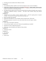
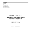
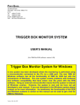
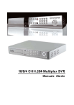
FIBER SIGMA 105 Hillcrest Road Flemington, New Jersey 08822-7173 U.S.A. Tel: +(908) 377-0763 Fax: +(908) 359-5735 E-mail: [email protected] Web: http://www.fibersigma.com TENSION for Windows: CONTROL PROGRAM FOR OPTICAL FIBER TENSILE TEST APPARATUS USER’S MANUAL (For TENSION software version 0.19) Version 0.19a, August 2010 Contents Contents................................................................................... 1 Introduction ............................................................................. 2 Hardware Installation .............................................................. 2 Hardware Assembly – Horizontal ..................................... 3 Hardware Assembly – Vertical.......................................... 3 Electrical Connections....................................................... 3 TENSION for Windows Software Installation........................ 5 Running the Software for the First Time ........................... 5 Uninstalling TENSION for Windows................................ 6 Updating the System Controller Firmware ........................ 6 Quick Start .............................................................................. 7 Checking Hardware Operation .......................................... 7 Breaking Your First Fiber.................................................. 7 The TENSION Windows ........................................................ 8 The Main Window............................................................. 8 Performing an Experiment........................................... 9 Loading Rate Parameters ............................................. 9 Preload Parameters ...................................................... 9 Experiment Parameters ................................................ 9 Fiber Parameters .......................................................... 9 Data Display Area...................................................... 10 Export Data Window ....................................................... 13 Contents Loading Rate Graph Window...........................................13 Graph Window .................................................................14 Set Zero Position Window................................................15 Options Window...............................................................16 Miscellaneous Options................................................16 Configuration Files .....................................................16 Calculator .........................................................................17 Hardware Setup Window .................................................17 Load Cell Calibration.............................................................18 How to Calibrate the Load Cell........................................18 When to Calibrate the Load Cell ......................................19 Review Calibration Window ............................................19 Calibrate Load Cell Window............................................20 Configuration Files.................................................................21 Troubleshooting .....................................................................23 Unable to Communicate with System Controller via the USB Port ..........................................................................23 The Motor is Obstructed by the Vertical Mounting Bracket .............................................................................23 Missing Features and Known Bugs........................................23 History....................................................................................23 1 TENSION for Windows User’s Manual Introduction TENSION for Windows Software Version 0.19 Warning: Operating This Equipment Can Be Hazardous Both the operator of the equipment and any other personnel in the same room must wear protective eyewear. When the fiber breaks it shatters into several fragments which can have considerable kinetic energy, potentially injuring people not involved with the measurement. Tensile testing is conceptually the simplest method for measuring the strength of a fiber specimen. However, the difficulty is gripping the ends of the fiber without causing damage and preferential failure at the grips. The most common solution for this problem is to wrap the fiber around a rubber coated capstan – the capstan effect means that the tension in the fiber is gradually transferred onto the capstan over two or three turns of the fiber so that stress concentrations are eliminated. The load applied to the fiber is measured using a precision load cell. When the fiber breaks the load cell signal drops abruptly and this event is used by the controlling computer to signify failure. The peak load is recorded and used to calculate the failure stress, i.e. the strength. Hardware Installation The Tensile Test Equipment is shipped almost fully assembled. However, the load cell assembly and the translation stage need to be attached the slides which are attached to the mounting rail. The load cell assembly is attached to the shorter slide using two ¼-20 by 1 inch screws. The translation stage is attached to the longer slide using two ½ inch long #10-32 screws inserted through two holes in the base of the translation stage which are accessed under the black bellows nearer the motor. The bellows can be pulled out of the way by gently detaching the Velcro at one side. The picture below shows the bellows detached and the arrows point to the heads of the two attachment screws. The positions of the translation stage and load cell assembly can be adjusted by loosening the clamping screws on each side using a 5 mm hex wrench. One of the screws on the load cell assembly is arrowed in the above left picture. TENSION for Windows User’s Manual 2 Warning: Make sure no dust or other foreign objects get into the space below the bellows. Carefully seal the bellows back into position with the Velcro attachments after mounting is complete. Hardware Assembly – Horizontal The rail on which the components are connected can be mounted in either the horizontal or vertical direction. For horizontal use, rotate the two 20 cm lengths of rail attached to the underside of the main rail until they are perpendicular to the main rail as shown in the pictures above. The short rails are attached to the main rail by socket head screws which are accessed through a hole in the middle of the underside of each short rail. Loosen these screws with a 5 mm hex wrench. Hardware Assembly – Vertical The load cell is most conveniently calibrated when the rail is mounted vertically (see the Load Cell Calibration section). The equipment also has a very small footprint when mounted vertically. For operation in the vertical direction, first firmly attach the vertical mounting bracket to a rigid horizontal surface. Then remove the 20 cm long rails from the main rail by loosening the screws attaching them to the main rail, which can be accessed through a small hole in the middle of each rail. Now loosen the clamping screws holding the slide supporting the translation stage and move the slide away from the end of the rail. Then place the end of the rail into the vertical mounting bracket and finger tighten the two screws in the side of the bracket to hold the rail firmly. Check the rail is vertical using a level – shims might need to be placed under one side of the vertical mounting bracket if it is not. In this configuration, for a half meter gauge length of fiber it will be found that the motor on the translation stage might be obstructed by the vertical bracket. If this is the case, remove the translation stage from the slide by removing the two screws under the bellows nearer the motor, rotate the stage 180° and reattach using the same two screws but now through holes accessed under the other bellows. Now the translation stage will need to be run backwards. Inform the TENSION program by checking the Reverse motor sense option in the Options Window. Electrical Connections Most of the cables used to connect the various parts of the tensile test apparatus are color coded - make sure that the color of the marker on the cable matches the color of the receptacle to which you connect it. Cables that are not color coded can usually only be connected in one place. 1. Connect the black cable with circular connectors to the motor housing on the translation stage and the circular connector on the rear of the Stepper Motor Controller. 3 TENSION for Windows User’s Manual 2. Make sure the stepper motor drive is turned off - the switch is on the rear panel. Two versions of the Stepper Motor Drive are currently in use. The version powered by the AC supply has the power switch integrated with the AC input module. The version powered by a 24 VDC external power brick has its power switch above the circular power input socket. In both cases, press the side of the switch marked “0”to turn off the power and “1” to turn on the power. 3. For the Stepper Motor Drive with AC supply, make sure that the fuse holder incorporated in the AC input module is oriented with your AC line voltage opposite the small arrow head on the housing. If it is not, the fuse holder can by prized out with a screwdriver, rotated and reinserted. For 220/240 VAC line voltage a 1 amp fuse should be used, and a 2 amp fuse for a 110/120 VAC line voltage. Both fuses are installed in the fuse holder. 4. Connect power to the Stepper Motor Drive using either the AC line cord or the 24 VDC, 2 A power brick. 5. Connect the D25 male-female cable (orange markings) between the male connector on the Stepper Motor Drive and the female connector on the System Controller. 6. Turn off the System Controller (power switch on the front panel is up) and check that the Program/Run switch on the rear panel is set to Run. 7. Connect the power supply to the System Controller using the socket on the rear panel. The power plug has purple markings. (Two power supply versions are in use, one is a dual 5 and 12 VDC supply with a 5 pin DIN plug, the other is a 24 VDC power brick with a 2.1 mm female plug. In the latter case, do not confuse the supply with the supply used for the Stepper Motor Drive - the Stepper Motor Drive supply is capable of providing greater than 2 A of current while the System Controller supply is approximately 1 A.) 8. Connect the D9 male-female cable (green markings) between the female Run socket on the rear of the System Controller and a serial port on the PC. 9. If the PC does not have a serial port, install the RS232-USB adapter, carefully following the instructions provided with the adapter. Once the adapter is connected to a USB port, connect the D9 male-female cable (green markings) between the female Run socket on the rear of the System Controller and the RS232-USB adapter. 10. Connect the load cell to the socket on the rear of the System Controller. Check that the connections resemble those in the following pictures (details of your units might differ slightly from these pictures): Rear panel connections for the Stepper Motor Drive. TENSION for Windows User’s Manual 4 Rear panel connections for the System Controller. The serial line is connected to the Run port. The Run/Program switch is shown in the Run position – make sure it is in that position. TENSION for Windows Software Installation Warning: Run Windows Update to get the latest Windows patches before attempting to install TENSION for Windows Warning: Uninstall previous versions of TENSION before installing a newer version Run the SETUP program obtained from the Fiber Sigma website (http://www.fibersigma.com/downloads) or from the distribution CD in the TENSION directory. If you want to use a USB port on your PC for connecting to the System Controller, install the software supplied with the serial to USB adaptor. Running the Software for the First Time TENSION for Windows can be used for 30 days before it will require activation – activation requires a license number supplied by Fiber Sigma. You do not need to activate the software immediately, but it will stop a nagging message that appears when the program is started. The software can be activated automatically if the computer has an Internet connection, or manually if it does not. If you select manual activation, TENSION provides an Installation Code which is needed together with the license number to get an Activation Key which can be obtained by filling in the form at: http://www.fibersigma.com/activation.html. This key permanently activates TENSION. Note that the Installation Code must be generated by running TENSION on the same computer on which TENSION will be used. Please contact us at [email protected] if you have any problems with the activation process. When the software is run for the first time it attempts to find the connection to the external microcontroller on one of the serial (COM) ports. (The USB to serial adapter, if used, looks like a COM port to the software). Whenever the TENSION software is started (not just on the first occasion) two additional steps must be taken before accessing the Main Window of the program: 1. After the hardware connection is specified, you will be need to synchronize the position of the translation stage capstan with the position indicated by the Stepper Motor Drive and the position indicated by the TENSION software. This is done in the Set Zero Position window. 2. Load cell calibration data need to be loaded into the program. By default the program uses the same calibration information as the last time it was run. However, the first time the program is run the Review Calibration window is automatically opened. A calibration file is supplied by Fiber Sigma - its name is “nnnnnn.CAL” where nnnnnn is the serial number of the load cell. The calibration data are loaded from the main Review Calibration window. When the data are loaded, make sure that the load 5 TENSION for Windows User’s Manual cell reads zero when there is no fiber loaded. If it is not close to zero, click the Zero/Tare button to adjust the calibration to read zero. You might then want to save the adjusted parameters to a disc file. 3. The software must be connected to a data file used to save all measurements as they are made. By default the same file used the last time the program was run is used, if it can be found. If not you are prompted to specify a file. After specifying the file, the data file name is displayed in the data area of the Main Window. Uninstalling TENSION for Windows TENSION for Windows can be uninstalled using either one of two methods: 1. Run the Unistall icon in the Fiber Sigma program folder (Start | Programs | Fiber Sigma). 2. Go to Start | Settings | Control Panel | Add or Remove Software and select TENSION and click Change/Remove. Updating the System Controller Firmware Warning: The Run/Program switch on the System Controller should be left in the Run position at all times except when updating the firmware using the instructions below. When a new version of the TENSION software is released it is usually necessary to update the System Controller firmware at the same time. TENSION will give an error message and halt if the System Controller firmware is out of date. Additionally, if the firmware is accidentally erased (e.g. by turning on the power with the Run/Program switch is set to Program) the power LED will be flashing and it is necessary to reprogram the firmware. Perform the following steps in the exact order given to update the firmware: 1. Locate the binary file containing an image of the firmware. This file can be found in the TENSION program directory (C:\Program Files\Fiber Sigma\TENSION by default). The file name is SC-nnn.BIN where nnn is the firmware version which normally matches the TENSION version. 2. Turn off the System Controller. 3. Move the Run/Program switch to Program (it is a locking switch; pull the switch paddle out to release the lock). 4. Connect the System Controller Program port to a serial port on the PC or to the USB/Serial adapter cable. 5. Turn on the System Controller. Wait until the power LED on the controller starts blinking. 6. In the same directory, run the RFU.EXE program. i. From the menu, select Setup | Communications and select the COM port that the System Controller is connected to. Leave the baud rate at its default value of 19200. ii. From the menu, select File | Load Flash Image and browse to the image file located in step 1. iii. If there are any error messages check that you have selected the correct COM port and that the three files COLDLOAD.BIN, FLASH.INI and PILOT.BIN are in the Program Files/FiberSigma/TENSION directory and that the correct locations are given for these three files in the Setup | File Locations menu. 7. Turn off the System Controller. 8. Move the Run/Program switch to Run. 9. Turn on the System Controller. 10. Connect the System Controller Run port to a serial port on the PC or to the USB/Serial adapter cable. The power LED on the System Controller should be on steadily. If it is flashing, carefully repeat the above steps. TENSION for Windows User’s Manual 6 Quick Start Refer to the Hardware Installation section for setting up the translation stage and load cell assemblies. 1. Make sure the Stepper Motor Drive is turned off – the switch is on the back panel next to the power receptacle. 2. For AC-line powered versions of the Stepper Motor Drive (shipped prior to mid 2005), make sure the correct AC voltage is selected on the input power module – the white triangle should point to the correct voltage. If it does not, carefully pry the fuse holder assembly out of the power entry module, rotate through 180° and insert back into the module. Make sure it contained a fuse. Versions of the Stepper Motor Drive shipped starting mid 2005 are powered by a 24 VDC universal power supply which can be powered by both 110 and 220/240 VAC power. 3. Connect the translation stage to the Stepper Motor Controller using the black sleeved cable with circular connectors on the end. The plug of each connector should be gently pushed into the receptacle and rotated until the mating notches align – the plug will then move further into the receptacle housing. Then rotate the locking ring clockwise until it clicks. This cable carries the power to the stepper motor and well as the signals for the hard limit switches in the translation stage which stop the stage being moved too far. Never connect or disconnect this cable while power is applied to the stepper motor. 4. Put all switches on the Stepper Motor Drive and Bend Control Unit to their default positions: SMD: Motor Current to remote SMD: Local Control to remote 5. Install the TENSION for Windows software by running the setup program. 6. Connect a D25 male-female cable between the Stepper Motor Drive and the connector on the rear of the System Controller – use the cable with orange labels and plug the female end into the socket on the rear of the Stepper Motor Drive labeled PC in orange. 7. Make sure the power switch on the System Controller is up (off). Connect the power supply to the connector on the rear panel. 8. Set the switch on the rear of the System Controller to run. 9. Connect the D9 male-female cable between the connector on the rear of the System Controller and a serial port on the PC. If the PC’s serial port has a 25 pin female connector, use the 25to 9 pin adapter provided. 10. If a USB port is used instead of a serial port, install the serial to USB adapter using the software provided. Follow the instructions exactly. 11. Power on the System Controller. Checking Hardware Operation Before attempting to break any fibers, go to the Hardware Setup Window and make sure that all input and output functions are operating correctly. You are now ready to break your first fiber! Breaking Your First Fiber Warning: Operating This Equipment Can Be Hazardous Both the operator of the equipment and any other personnel in the same room must wear protective eyewear. When the fiber breaks it shatters into several fragments which can have considerable kinetic energy, potentially injuring people not involved with the measurement. 1. Check that the fiber diameter and other parameters are correctly set in the Main Window. 2. Click Load fiber and wait until the capstan has finished moving. Make sure that the distance between the centers of the capstans, measured along the fiber axis, is equal to the gauge length specified in the Main Window. 7 TENSION for Windows User’s Manual 3. Take a length of fiber approximately one meter longer than the gauge length. Wrap the ends around the capstans, starting the wraps so that the fiber in the gauge length contacts the capstans along the line of action of for the load cell. This line is defined by the axis of the screw connecting the capstan plate to the top of the load cell. The load axis intersects the capstans approximately ¼ of the way across the rubber tape on the capstans. So, wrap the fiber around the capstans for about three turns making sure the turns do not overlap and secure the loose fiber ends to the capstans with a small piece of adhesive tape. 4. Set the desired loading rate. If a stress or strain rate is specified the capstan will be moved at a varying speed designed to give the precise loading rate requested. 5. Click Break fiber and wait until the break is detected. If the fiber broke successfully select OK. You will then be able to review the loading behavior in detail in the Loading Rate Graph window. The TENSION Windows This section describes all the windows in the TENSION program: The Main Window Export Data Window Loading Rate Graph Window Graph Window Set Zero Position Window Options Window Calculator Hardware Setup Window Review Calibration Window Load Cell Calibration Window The Main Window TENSION for Windows User’s Manual 8 This window is at the heart of the program. Experiments are run from this window and other windows are all accessed from here. The main window displays all key experimental parameters. These sections of the main window are described below: Performing an Experiment Load fiber The translation stage is move to the zero position when the capstans are separated by the gauge length. Break fiber The capstans are moved apart until the fiber breaks. If preloading is specified the capstan moves at the translation stage’s maximum speed to the preload position before continuing at the rate specified by the loading rate parameters. Go to Specify a capstan position in microns. The translation stage will move at its maximum speed. Set Zero position Opens the Set Zero Position window. This is used to reset or check the zero position. Loading Rate Parameters Three types of experiment can be run; constant capstan speed, constant stress rate or constant strain rate. It is planned to implement static fatigue (constant load/stress/strain) in the near future. Preload Parameters For very slow loading rates the experiment can be shortened by rapidly loading the fiber to some specified level, after which the rate drops to the needed slow value. Preloading can dramatically shorten experiment duration without affecting the results since little fatigue occurs at low stress. As an example, FOTP-28C for tensile testing of fibers permits preloading to a stress no more than ½ the strength of the weakest specimen. Experiment Parameters Gauge length This specifies the length of fiber under test. It is the distance between the centers of the capstans measured along the loading axis. It is also the distance between where the fiber attaches to the faceplates. Rate calc This parameter determines how much of the load/time data are used to calculate the actual loading rate achieved. Loading rates are calculated from all data that exceed this portion of the failure load. For the default of 80% it means that the top 20% of that data are used for rate calculations. FOTP28 specifies 80% of the failure load. Specimen number This is the index number for the next specimen to be broken. This index number is the parameter “N” in the first column of the Result Table. Fiber Parameters Fiber diameter Sets the fiber diameter in µm. This is the diameter of the glass in the fiber. Coating EA 9 TENSION for Windows User’s Manual This is the product of the Young’s modulus and the cross-sectional area of the polymer coating. It is used to calculate how much of the applied load is supported by the glass and how much by the coating. Modulus This is the elastic modulus of the glass in the limit of zero strain, E0, in GPa. The default value is 72 GPa for silica. Modulus a This is the coefficient which describes the strain dependence of the elastic modulus. The default value is 3 for silica. The elastic modulus (Young’s modulus) of silica, E, varies with strain, e, according to the equation: E = E0 (1 + a e). TENSION calculates the stress in the fiber surface, s, using this strain dependent modulus: s = E e = E0 (e + a e2). Data Display Area When fibers are broken the results are displayed in the Result Table. They are also saved to the current data file. This section of the Main Window shows the name of the current output file for the results. The file name includes the full path to the file - if the result is too long to fit in the available space part of the path may be replaced by ellipses. In that case, simply hover the mouse over the file name and the complete path and name will be displayed in the “tool tip” which appears when hovering. The Result Table The result table lists all results currently stored in the data file. The table can be configured to your liking and the display can be manipulated in various ways. The Result Table contains the following: The first column is grayed out and can not be edited. This contains the line number in the data file for each row/measurement. Note that even if the table is sorted in some order, the data file contains the data in order of this line number. N sequence number of the break Lt the total load applied to the fiber in newtons (N). This is the load supported by both the glass and the coating. Lf the load applied to the glass fiber in newtons (N). This is the total load less the load supported by the coating. This load is used to calculate the failure stress. The total load and the fiber load will be the same if the coating EA (product of coating modulus x area) is zero. s failure stress (MPa) e failure strain (%) nom nominal loading rate, which might be in terms of capstan speed (µm/s) or stress rate (MPa/s) or strain rate (%/min) rate v capstan speed (µm/s) averaged starting at 80% (default) of the failure load error in the estimate of the capstan speed (µm/s) e. strain rate de/dt (%/min) averaged starting at 80% of the failure load error in the estimate of the strain rate (%/min) s. stress rate ds/dt (MPa/s) averaged starting at 80% of the failure load error in the estimate of the stress rate (MPa/s) t time to failure; time from start of experiment to failure (s) date date at failure, format is year/month/day so that sorting in alphanumerically also sorts in date order time time at failure TENSION for Windows User’s Manual 10 commen t comments can be inserted in this column df GL EA Eo Ea Preload start This single column contains a variety of parameters that are not normally needed themselves for later data analysis. However, they are included because they are all parameters that might affect the results – they are included so you can check you used the right values for them. Their meaning: df fiber diameter (µm), i.e. the diameter of the glass not the diameter of the coating or buffer GL gauge length (mm) EA product of the Young’s modulus and sectional area of the coating or buffer (N). Eo zero strain elastic modulus (72 GPa for silica) Ea first order strain correction to the elastic modulus (3 for silica) Prelo the amount of preloading rapidly applied to the fiber before the specified loading rate is applied. Depending on how the preload is specified it might be in N, MPa or %. ad start date and time the measurement is started Result Table Actions Several actions can be used to customize the data display, export the data or add comments. Many of these actions can be performed by right clicking anywhere in the table. The above context sensitive menu is shown. The contents of the menu depend on the cell that was right clicked on. Some of these actions can be performed in other ways, such as using the keyboard or the menu. Sort data Double click a column header to sort the table by that column. To sort descending, double click the column header again. Alternatively, right click anywhere in the column and select “Sort column nnn”. Repeat to sort descending Resize a column Hover the mouse over the vertical bar on the right of the column title. When the mouse cursor turns into two vertical lines, the bar can be dragged to select any column width. Resize one or all columns to fit Right click anywhere in the column and select “Fit width of column nnn” and the column width will be set to a minimum that still makes all data in that column visible. Select “Fit all column widths” to perform the same action on all columns of the table. Hide a column 11 TENSION for Windows User’s Manual Resize the column to its minimum width or right click in the column and select “Hide column nnn”. Make all columns visible To make all hidden columns visible, right click anywhere in the table and select “Unhide all columns”. Select a block or column To select a single column click in the column header. To select multiple columns click in the left column header and drag the mouse and release it in the right column header (or vice versa). Note: when a column or columns are selected, all cells in those columns are selected even if some rows are not visible because the table is scrolled. Note: when multiple columns are selected, hidden columns between them are not selected. To select a block of cells in the table click in one corner of the block, drag the mouse and release it in the opposite corner of the block. Copy data to clipboard The selected block or column of data can be copied to the clipboard by typing Ctrl-C, by rightclicking anywhere in the result table and selecting “Copy selection to clipboard”, or by clicking the Export data button (which opens the Export Data Window) and setting the data destination to the clipboard. For the first two methods the items within a selected row are separated by tab characters and rows are separated by new line characters (carriage returns). Any item, such as a comment, containing a space or comma is wrapped in double quotes. This format is suitable for immediately pasting into, e.g. Excel. Add/edit comment To add or edit a comment in a row, click in the comment cell and start typing or right click anywhere in the row and select “Edit comment for row nn”. Delete a row No mechanism is provided for deleting a row – this avoids accidental deletion. If you want to ignore a result, add a comment to the row reminding you to do this during data reduction. This approach keeps a record or any data that are later ignored and avoids any accusation of data editing. Data File Functions Open data file Use this to change the file being used to save results. If the file does not exist already, a new one is created. Save data file Saves the contents of the current results to a file. That file becomes the new file for saving results. Export data Opens the Export Data Window. Review last Reopens the Loading Rate Graph window for the last specimen. TENSION for Windows User’s Manual 12 Export Data Window This window permits results contained in the Result Table to be exported from the TENSION program. The whole results sheet can be exported, or only the visible columns (i.e. all unhidden columns; columns that are scrolled outside the results box are considered visible), or cells that have been selected with the mouse. Output can either be sent to a comma delimited text file where each row of the results table is a line in the output file and each cell in a row is separated by commas. This is a standard format that can be recognized by and imported into many programs. Alternatively, the results can be placed in the clipboard, delimited by tabs characters between cells, and pasted directly into many applications, such as Excel or SigmaPlot. The column headers can be included in the output if Include column names is checked. The same data export functions are available from the menu bar in the Main Window under Export data. Also right clicking anywhere in the results table brings up a context sensitive menu, one option of which copies the selected cells to the clipboard. Loading Rate Graph Window After a fiber is broken the following window opens showing details of the load/stress/strain/position vs time behavior. In this particular example a large number of overlapping data points were captured making the charts a little ugly. Clicking the Dots / lines button toggles between showing dots at each data point and showing lines joining the points: 13 TENSION for Windows User’s Manual The actual loading rates achieved (speed, stress rate and strain rate) are calculated by regression fitting to the data for loads exceeding 80% of the failure load (this parameter can be changed in the Experiment Parameters section of the main window). The top 20% of the data are shown in yellow and the blue lines are regression fits to the data. Clicking the Copy data to clipboard button puts all the data into the clipboard ready for pasting into another application such as Excel or SigmaPlot. The graphs shown depend on the type of experiment. The above examples are for a constant capstan speed. Because of slippage of the fiber over the capstans a constant speed does not result in a constant loading rate. However, when the type of experiment is set to a stress or strain rate in the Loading Rate Parameters section of the main window, the speed of the stepper motor is servo controlled to obtain the precise loading rate requested. Double clicking on any of the three graphs shows a bigger version of the graph in the Graph Window. Graph Window The graph window provides a detailed view of several different kinds of data. Depending on the loading mode set in the Loading Rate Parameters section of the main window, the graph window can show fiber load, stress, strain, or capstan position versus time. Also it is used to display details of load cell calibration data from the Calibrate Load Cell window. This graph window is opened by double clicking one of the graphs in the other windows. TENSION for Windows User’s Manual 14 The above graphs are examples taken from a servo-controlled constant stress rate experiment. Because of slippage at the capstans a constant loading rate is not achieved by a constant capstan speed. However, by varying the capstan speed during the experiment (left/upper) a precise stress rate is achieved (right/lower). This technique means that the TENSION for Windows software greatly exceeds the loading rate requirements of all current standard testing procedures (TIA, IEC, etc.), over the entire load range, not just for the top 20% of the data. Clicking the Copy button in any of the graph windows copies to the clipboard both the graph (in bit map format) and the data displayed by the graphs. Either the graph or the data can be pasted into other applications - which gets pasted depends on the application. For example, Paint pastes the graph while SigmaPlot pastes the data. By default the data are pasted into Excel and Word but the graph can also be pasted using Paste Special. Note that the graph window can be resized to obtain bigger graphs with more resolution. Set Zero Position Window The position of the translation stage must be synchronized with the Stepper Motor Drive and with the TENSION software. This is normally done by moving the capstan close to the limit of travel of the translation stage. Often the TENSION software can recover the last translation stage position from the System Controller. Run to close limit Click this button to move the translation stage to 500 µm from the limit of its travel - this maximize the travel available for loading the fiber. Set position 15 TENSION for Windows User’s Manual If the software is stopped it loses information on the capstan position. If the position is known (the position displayed on the Stepper Motor Drive is known to be correct) use this option to enter the current position of the faceplates. Options Window This window is used to set various options: Miscellaneous Options Noisy If this option is checked, then the System Controller clicks when each step is taken by the motor. This provides auditory feedback on the progress of an experiment. If the clicking/buzzing is annoying, clear this box. ReverseSense reverse motor When checked the sense of the translation stage/motor rotation are reversed. This can be used if custom faceplates are mounted at the motor end of the translation stage instead of the other end. Note that the position displayed by the Stepper Motor Drive will be the negative of the value shown by TENSION. Maximum step rate This shows the maximum speed of the stepper motor in steps per second. It can not be modified by the user. Sound to play Future implementations will permit the choice of a sound to play when the fibers break. Currently there is only one sound - the system beep. Configuration Files Configuration Files can be used to automatically set up TENSION parameters. Configuration files are plain text files containing one or more lines. Each line consists of the name of a parameter followed by a value for that parameter. The Options window can be used to read and write configuration information. TENSION for Windows User’s Manual 16 Calculator A calculator is built into the program for making a variety of calculations for two-point bending. Set the fiber and miscellaneous parameters appropriately and then enter one of the three parameters, stress, strain, or faceplate gap. The other two parameters will then be calculated. Note the dependent parameter will be highlighted in yellow. The calculator is useful, for example, when planning static fatigue experiments, checking results, etc. Hardware Setup Window This window is useful for checking the operation of the system electronics and interfacing. The apparatus is controlled by several digital input and output lines from the System Controller. Output bits can be toggled: Step open the position counter should count up Step close the position counter should count down Direction should have no noticeable effect Current the current high LED on the Stepper Motor Drive should blink on and off (make sure the motor current selector switch is set to “remote”) Tick toggles the speaker in the System Controller so that the speaker gives a faint click The status of the input bits can be monitored: Open limit is high when either the open limit is active or the Stepper Motor Drive is in local mode 17 TENSION for Windows User’s Manual Close limit is high when either the close limit is active or the Stepper Motor Drive is in local mode Stop button is high when the emergency stop button on the front panel of the System Controller is pressed Break detect the state of this line is ignored by TENSION Contact the state of this line is ignored by TENSION Contact disable the state of this line is ignored by TENSION Load Cell Calibration How to Calibrate the Load Cell When to Calibrate the Load Cell Review Calibration Window Calibrate Load Cell Window The load cell needs to be carefully calibrated for accurate operation of the equipment. If you are using standard test techniques please consult these documents since they will specify how and how accurately the load cell should be calibrated. Typically they require that a range of weights be applied to the load cell around the region of loads at which the fiber is expected to break. The results are then used to calculate an arbitrary load by linear interpolation of the calibration data. For example, FOTP-28 specifies that the load cell be calibrated using a minimum of three weights bracketing the expected failure loads, and that the calibration be to an accuracy of 0.5%. If a broad range of calibration weights are used, the load cell used in the our equipment typically exceeds this requirement by an order of magnitude over the entire range of the load cell (the default is a 25 lb = 11.3 kg capacity load cell). This permits one calibration to serve a variety of experiments high loads for strength measurement of pristine fiber and low loads for coating strip force measurement. The analog-to-digital (A/D) converter in the System Controller used to measure the load cell amplifier output has three channels with different gain settings. The default, channel 0, uses the entire range of the load cell. Channel 1 has twice the gain of channel 0 but therefore can only use half of the load cell capacity (i.e. 12.5 lb = 5.7 kg for the standard load cell). Channel 2 has five times the gain of channel 0 but can only access a fifth of the load cell capacity (i.e. 5 lb = 2.3 kg for the standard load cell). Using channels 1 or 2 therefore enable higher precision measurements of low loads, e.g. for studying weak fiber. The noise levels are proportionately lower as well. The TENSION software has built in to it software for determining the calibration parameters as well as the precision of the calibration. How to Calibrate the Load Cell There are several ways to calibrate the load cell. Consult any standard test procedures you are using for details. However, the following method works well and leads to calibrations that substantially exceed all standard specifications we have seen. 1. Mount the support rail vertically using the mounting bracket supplied with the equipment. Make sure that the load cell is at the top with its direction of action (marked with an arrow) pointing down. The translation stage can be removed from the rail or at least the capstan on it can be removed to be out of the way. 2. A string with a metal ring is supplied with the equipment. Wrap the string around the load cell capstan, criss-crossing the wraps to get a good grip. Make sure that the ring hangs down with the string along the line of action of the load cell, i.e. collinear with the screw at the top of the load cell. 3. Let the equipment run for 24 hours to ensure thermal stability before calibrating or before making measurements. 4. In the Main Window click Calibrate, then in the Review Calibration window click New calibration which opens the Calibrate Load Cell window. TENSION for Windows User’s Manual 18 5. Enter the serial number of the load cell. Also specify the A/D channel that is to be used. Channel 0 is the channel normally used. 6. Hang a series of weights on the ring, entering the weight and pressing Add point for each. Repeat until the needed weight range is covered. The data table and the lower graph show the residues for each point. If a point has a large residue, check the calibration weight or repeat, making sure that the weight is stationary before clicking Add point. 7. Click Finish and when prompted accept these data. 8. Reposition the equipment in the orientation it will be used in. Attach any mounting fixtures to the load cell assembly. The load will now probably not read zero in the Review Calibration window since the weight of the fixtures has changed. Click Zero / Tare to apply an offset to the calibration to force it to read zero. 9. Click Save to disc to save the calibration data to disc. While TENSION will remember the calibration data each time it is started, it is useful save to disc in case the calibration is overwritten. When to Calibrate the Load Cell A full calibration of the load cell is needed under these circumstances: 1. When the equipment is first received. It is shipped with calibration data but the end user should ensure proper calibration. 2. When either the load cell or the System Controller is changed. 3. Periodically - perhaps once a week - apply weights to the load cell and make sure the correct force is shown in the Review Calibration window. If it shows significant error, perform another calibration. Review Calibration Window This window shows the current calibration parameters and an estimate of their errors. A careful calibration will produce parameters which have only a fraction of a percent error. Note that the load cell serial number is saved with the calibration data as well as the A/D channel used for the calibration. Other functions can be performed in this window: Zero / Tare Adjust the calibration intercept to force the load to read zero. Save to disc Save the current calibration parameters to a disc file. Load from disc Load calibration parameters from disc New calibration Opens the Calibrate Load Cell window 19 TENSION for Windows User’s Manual Calibrate Load Cell Window This window displays various diagnostic information related to the load cell calibration. It is also used for generating and visualizing calibration data. The Calibration parameters section shows the calibration parameters currently used by TENSION as well as the parameters resulting from the calibration measurements currently being made. The Add/remove calibration points section is where you can enter the mass of the weight currently applied to the load cell. It permits entry in any of three units which can be mixed and matched. The signal is shown - wait until the signal stabilizes before clicking Add point. It will stabilize faster if the weight is not swinging. A bad point can be removed by clicking Remove point after which the row of the bad point needs to be given. A bad point can also be removed by right-clicking on its row in the data grid. The analog-to-digital (A/D) channel to be used can be changed by clicking the A/D Channel button. Any calibration points will be deleted when the A/D channel is changed. Channel 0 is the default and it uses the entire measurement range of the load cell. Channel 1 has twice the gain and channel 2 has five times the gain of channel 0. Graphs: The calibration points are displayed both in the data grid and in the graphs on the right. The upper graph is the A/D converter output signal (in arbitrary units) versus the applied load (N). The blue line is a regression fit to the data. The lower graph show the residues for the regression fit versus load, i.e. the residue is the vertical distance between a point and the regression line. Poor points (caused by a swinging weight or a weight of poor accuracy) show up as deviating significantly from zero. Double clicking on either graph opens the Graph Window which shows an enlarged version. A button on that window permits both the data and the graph to be copied to the clipboard. The Calibration data section displays information on the measurements. It includes the load with the specified units, the load converted to newtons (N), the A/D reading for that load and the residues from the regression line. The contents of this table can be copied to the clipboard by clicking the Copy to clipboard button. TENSION for Windows User’s Manual 20 Configuration Files Configuration files are plain text files that contain settings for various program parameters. Reading a configuration file will automatically set the values for the defined parameters. They can be used to quickly set several parameters at once. For example, you could create a file FOTP-28.INI which would specify parameters that are compatible with the FOTP-28 standard test procedure: ExptType 2 ExptStrainRate 50 GaugeLength 500 If the translation stage is turned through 180° so that the motor is between the capstans (reducing the overall length of the system) one could tell TENSION that the motor direction is reversed: ReverseSense True The configuration files can be constructed using a plain text editor such as NotePad. As a starting template, you can create a file containing all available configuration parameters using the write configuration file option. You can then delete irrelevant parameters and adjust others as necessary. A complete list of Configuration File Parameters follows: Configuration File Parameters The available configuration parameters are listed below, together with their default values. Note however, that many parameters are saved when the TENSION program is closed. ExptType 0 ExptSpeed 5000 ExptStressRate 60 ExptStrainRate 50 PreloadType 0 PreloadLoad 0 PreloadStress 0 PreloadStrain 0 SpecimenCount 1 WaitBeforeBreak 0 FiberDiameter 125 Modulus 72 ModulusA 3 This parameter specifies what type of measurement should be made: 0 – constant capstan speed 1 – constant stress rate 2 – constant strain rate 3 – constant stress (static fatigue) Specifies the capstan speed in µm/s for a constant speed experiment. Specifies the stress rate in MPa/s for a constant stress rate experiment. Specifies the strain rate in %/min for a constant strain rate experiment. Specifies how the preloading is defined: 0 – no preloading 1 – load 2 – stress 3 – strain Specifies the preload load in N. Specifies the preload stress in MPa. Specifies the preload strain in %. Sets the index number of the next fiber to be broken. Not yet implemented. Diameter of the fiber in µm. This is the diameter of the glass – it is the diameter at the position where the fracture initiates. Elastic modulus of the glass in the limit of zero strain in GPa. The value of 72 is appropriate for fused silica. See the Fiber Parameters section for more information. This dimensionless parameters describes how the elastic modulus of the fiber varies with strain. The value of 2.125 is appropriate for silica being deformed in bending. See the Fiber Parameters section for more information. 21 TENSION for Windows User’s Manual CoatingEA 0 Noisy True HiCurrRate 10 ReverseSense False MinBreakLoad 5 BreakFactor 0.5 GaugeLength 500 ComplianceFactor 1.3 inServoLoad 0.5 RateCalculation% 80 This parameter is the product of the Young’s modulus and cross-sectional area of the polymer coating on the fiber in newtons (N). It is used to calculate how much of the applied load is supported by the coating and how much by the fiber. For many systems the coating stiffness is negligible compared to the fiber so the value of zero is acceptable. For multiple concentric polymer coatings, simply add the modulus x area for each layer to get the total EA. If this parameter is set to true, then the System Controller clicks when each step is taken by the motor. This provides auditory feedback on the progress of an experiment. If the clicking/buzzing is annoying, set this parameter to false. When the translation stage is moved at a speed (µm/s) greater than the value defined by this parameter then the motor current is increased for the move. If the speed is less than this value, TENSION will drop the current to the lower standby current to avoid heating effects in slow, long-duration tests. The motor current will only be low if the Motor Current switch on the Stepper Motor Drive is set to remote. Set to false for normal operation. When set to true the sense of the translation stage/motor rotation are reversed. This can be used if custom faceplates are mounted at the motor end of the translation stage instead of the other end. Note that the position displayed by the Stepper Motor Drive will be the negative of the value shown by TENSION. This parameter prevents premature detection of a break early in the loading cycle. This parameter sets the load (N) below which a break will not be detected. This parameter would need a smaller value if testing very weak fibers. The TENSION software tracks the maximum load that has been applied to the fiber. When the applied load drops below this fraction of the maximum load the software interprets it as a break. This is the length of fiber under test (in mm). It is the distance between the surfaces of the capstans where the fiber contacts them. This is the same as the distance between the centers of the capstans measured along the line of action of the force. This parameter is used by the servo control used for the constant stress rate and constant strain rate modes. It is used to calculate the starting speed of the capstan before servo control takes over. A compliance factor of one would be for a fiber that does not slip and for infinitely rigid capstans (including the rubber coating). This is never achieved! If this parameter is badly wrong the servo system will take some time to settle on the correct loading rate. If the capstan starts too slow and then speeds up too much and overshoots, increase the compliance factor. If the capstan starts too fast, slows up and undershoots, decreasse this parameter. The default of 1.3 is good for many situations and works well for 125 µm diameter glass fibers and a 500 mm gauge length. This parameter is used by the servo control used for the constant stress rate and constant strain rate modes. The capstan moves at a constant speed until this load in newtons (N) is reached; the software then switches to servo control mode. This parameter stops the servo control system overreacting when there is some slack in the fiber. This parameter might need to be reduced for weak fiber. The loading rates are calculated from the load/time data starting at this percentage of the failure load, i.e. for the default of 80% it means the top 20% of the data are considered. This is specified, for example, by FOTP-28. TENSION for Windows User’s Manual 22 Troubleshooting This section lists some common problems encountered by users, and how to overcome them. If you have any suggestions for this section, we will be glad to include them. The following topics are addressed: Unable to Communicate with System Controller via the USB Port The Motor is Obstructed by the Vertical Mounting Bracket Unable to Communicate with System Controller via the USB Port Symptom: TENSION can not find the system controller. Cause: The USB to serial adapter cable sometimes gets confused about what type of device it actually is. Solution: Turn off the System Controller. Disconnect both ends of the USB to serial adapter. Connect the USB end to the PC and wait until you get “bong” and a message saying that the new hardware is ready to be used. Connect the other end of the cable to the System Controller. Turn on the System Controller. Restart TENSION. Cause: The firmware in the System Controller has been erased or is corrupt. Solution: Reinstall the firmware. See the section on Updating the System Controller Firmware. The Motor is Obstructed by the Vertical Mounting Bracket Symptom: When the rail is mounted vertically, the motor can be obstructed by the vertical mounting bracket so that the full ½ meter gauge length can not be realized. Solution: Reverse the translation stage - the motor is then between the two capstans so shortening the overall system length. The Reverse motor sense option should then be selected in the Options Window. Please let us know of any problems you have - whether or not you solved them. Your experiences will be useful to others. Missing Features and Known Bugs Missing Features Static fatigue Proof testing Optional sounds to play when a fiber breaks Automated updating of System Controller firmware Reset all configuration parameters to defaults Known Bugs Please report any bugs or errors. Please also suggest any way in which the software can be improved. History Version 0.19 No significant changes. Version 0.18 Fixed “subscript out of range” bug when starting a calibration (introduced in version 0.17). Version 0.17 Maintenance release. Version 0.16 23 TENSION for Windows User’s Manual Fixed bugs associated with load cell calibration window. Version 0.15 Fixed additional problems with how Greek characters display in Asian versions of Windows. Further improvements have been made to sorting the Results Table. Sorting multiple columns can be performed by sorting the individual columns in sequence. Sorting by date also sorts by time so that the results are sorted into exact chronological order. The Motor Moving window now has a check box which locks the keyboard so that the motor can not be stopped by accidentally entering a keystroke. This helps avoid accidents during long duration experiments. Version 0.14 TENSION can be run without a System Controller attached – useful for exporting data or using the calculator. Detection of the System Controller has been improved. Improved sorting of the data grid. Support has been added for a user selectable sound to be played when a fiber breaks. All program parameters can now be reset to their default values from the Options window. Version 0.13 Ctrl-C copies selected data to clipboard. A better software installer is now used. Shortcut for uninstallation now installed. Added ReverseSense configuration parameter. Added more status information to the Hardware Setup window. Version 0.12 Maintenance release. Version 0.11 Not released. Version 0.10 Initial release. TENSION for Windows User’s Manual 24