1
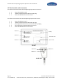
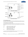
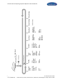
Claymate... Technology that Counts Wi-Card Sporting Claymate Operator and User Manual Page | 1 V. 1.1 (15032010) Promatic International Limited Station Works, Hooton, Ellesmere Port, CH66 7NF, United Kingdom +44 (0) 151 327 2220 Promatic Wi-Card Sporting Claymate Operator and User Manual Thank you for choosing Promatic Wi-Card Sporting Claymate. The Promatic Wi-Card Sporting Claymate is part of the Promatic Claymate shooting ground management system, which maintains the integrity of shooting disciplines, enables charging for released targets and provides auditing functions to optimise your ground. Table of Contents 1.0 The Controller and Accessories..................................................................................................... 3 1.1 Connecting the handset ........................................................................................................................... 4 1.2 Connecting your Controller (Cable) ......................................................................................................... 4 1.3 Powering from Promatic Traps (Cable) .................................................................................................... 5 1.4 Connecting your Controller (Radio) ......................................................................................................... 5 1.5 Retro-fitting of Radio using a cable connected Controller ....................................................................... 5 1.6 Button Test............................................................................................................................................... 5 2.0 First Time Run / Quick Start .......................................................................................................... 6 3.0 The Service Menu ......................................................................................................................... 8 3.1 Card detection and automatic Audit ........................................................................................................ 8 3.2 Controller Lock ......................................................................................................................................... 8 3.3 Accessing Service Menu ........................................................................................................................... 8 3.4 Trap Count Values (default A=1, B=1) ...................................................................................................... 8 3.5 FreePlay (default OFF) MasterCard Full Access, GroundCard OFF Only ................................................... 9 3.6 Target Limit (default ON) MasterCard Only ............................................................................................. 9 3.7 Cost Code MasterCard Only ..................................................................................................................... 9 3.8 Cycle Timers (default 3.0s) ....................................................................................................................... 9 3.9 Release Dwell (default 0.3s) ................................................................................................................... 10 3.10 Default Setting ..................................................................................................................................... 10 3.11 DC Input Voltage .................................................................................................................................. 10 4.0 Help ............................................................................................................................................. 11 5.0 User Instructions ......................................................................................................................... 12 Page | 2 V. 1.1 (15032010) Promatic International Limited Station Works, Hooton, Ellesmere Port, CH66 7NF, United Kingdom +44 (0) 151 327 2220 Promatic Wi-Card Sporting Claymate Operator and User Manual 1.0 The Controller and Accessories The cable connected Promatic Wi-Card Sporting Claymate set consists of: 1 1 1 Controller (Cable version) 3-button handset with 5m cable and 4-pin plug Controller Wall Bracket or Floor Stand The radio connected Promatic Wi-Card Sporting Claymate set consists: 1 1 1 2 1 Controller (Radio Version) 3-button handset with 5m cable and 4-pin plug pre-programmed button-less transmitter with 7-pin plug pre-programmed standard Claymate receivers Controller Wall Bracket or Floor Stand F3-button Display F2-button Card reader area F1-button Clip for Cards FRONT Hi-A button Lo-B button PAIR button HAND SET Page | 3 V. 1.1 (15032010) Promatic International Limited Station Works, Hooton, Ellesmere Port, CH66 7NF, United Kingdom +44 (0) 151 327 2220 Promatic Wi-Card Sporting Claymate Operator and User Manual Mounting screws Grey (Trap A) 3 core 4-pin Handset connector Black (Trap B) 2 core Factory Serial Number White 12V DC 2 core BACK CABLE VERSION Mounting screws 7-pin Radio Connector 4-pin Handset connector Factory Serial Number White 12V DC 2 core BACK RADIO VERSION 1.1 Connecting the handset The supplied Handset can be connected to either 4-pin Handset Connector mounted on the rear of the Controller. An optional additional Handset can be connected to the spare connector if required. 1.2 Connecting your Controller (Cable) The cabled Wi-Card Sporting Claymate Controller has three cables exiting the rear of the controller, with 3-pin rubber covered connectors attached to the Grey and Black cables. Connection should be as follows: White - Brown core connects to positive (+) 12v DC Blue core connects to negative (–) 0v DC Grey - Black core 1 connects to trap A release Black core 2 connects to trap A release Green/Yellow core is not used Black - Brown core connects to trap B release Blue core connects to trap B release The Controller uses volt free isolated relay contacts to connect to the external traps enabling connection to traps with varying voltages form 12v DC to 110v AC. Page | 4 V. 1.1 (15032010) Promatic International Limited Station Works, Hooton, Ellesmere Port, CH66 7NF, United Kingdom +44 (0) 151 327 2220 Promatic Wi-Card Sporting Claymate Operator and User Manual 1.3 Powering from Promatic Traps (Cable) The Controller comes prewired to connect directly to Promatic traps utilising the existing 2 core command cables and 3-pin rubber covered connectors. Together with a locally positioned 12v DC supply. 12v DC power can also be derived from one of the traps utilising a 3 core cable which replaces the standard 2 core Promatic command cable. If this method is preferred and uses trap A as the powering trap, the Controller cables should be connected as follows: White - Brown core connects to positive (+) 12v DC (E-Pin of 3-pin connector from trap A) Blue core connects to negative (-) 0v DC (L-Pin of 3-pin connector from trap A) Grey - Black core 1 connects to trap A release (N-Pin of 3-pin connector from trap A) Black core 2 connects to trap A release (L-Pin of 3-connector from trap A) Green/Yellow core is not used Black - Brown core connects to trap B release Blue core connects to trap B release NOTE: When using this wiring method, the voltage of the power supply to the trap and Controller can be read from the display in the Service menu. Operation of Claymate Controllers below 10v DC is not recommended. 1.4 Connecting your Controller (Radio) The Wi-Card Sporting Claymate Controller (Radio) has one white cable exiting the rear of the controller. Connection should be as follows: White - Brown core connects to positive (+) 12v DC Blue core connects to negative (–) 0v DC The button-less transmitter module connects to the 7-pin Radio Connector on the rear of Controller. The two pre-programmed Claymate receivers can be directly plugged into Promatic traps using the 3-pin connectors. The receivers use volt free isolated relay contacts to connect to the external traps enabling connection to traps with varying voltages form 12v DC to 110v AC. Grey - Black core 1 connects to positive (+) 12v DC (E-Pin of 3-pin connector) Black core 2 connects to negative (-) 0v DC (L-Pin of 3-pin connector) Black core 3 connects to release/switching (N-pin of 3-pin connector) Green/Yellow core is not used 1.5 Retro-fitting of Radio using a cable connected Controller There is an option of fitting a Break-Out Box (BOB) to a cabled Controller, which provides a 7-pin connector to fit a standard Claymate radio sender and receiver set. Please contact Promatic for further information. 1.6 Button Test After connecting the Controller and Handset, press each button, one by one to do a button test and confirm correct connection of the Handset. A sound will be heard and the button description can be read on the display of the Controller. Page | 5 V. 1.1 (15032010) Promatic International Limited Station Works, Hooton, Ellesmere Port, CH66 7NF, United Kingdom +44 (0) 151 327 2220 Promatic Wi-Card Sporting Claymate Operator and User Manual 2.0 First Time Run / Quick Start When a new controller is connected for the first time the display will ask for a MasterCard to be inserted. Insert the MasterCard in the clip on the front of to the Controller. The Controller will automatically set the unique Ground Code and local settings and allocate a Controller ID number. Once the ground code is displayed, remove the MasterCard and the “Ground” Serial Number will be briefly displayed. This number can be used for auditing the traps. (See Claymate Card Reset Unit Manual for details) The display will now alternate between 2 screens Shows unit ID and target count per trap. Shows unit ID and requests card Assuming both connected traps are single throwers, and the ground is running target based cards, the Controller is now ready for use by shooters. Page | 6 V. 1.1 (15032010) Promatic International Limited Station Works, Hooton, Ellesmere Port, CH66 7NF, United Kingdom +44 (0) 151 327 2220 Page | 7 V. 1.1 (15032010) FreePlay FreePlay permits targets to be thrown without a card present Default: FreePlay Off Number of clays thrown per trap 1 = 1 clay 2 = double n/c = no trap Default: A=1 B=1 Default: Target Limit On Target Limit ON restricts maximum number of targets thrown each time to 2 Target Limit to scroll through menu within 5 seconds Trap Count Values F1 Stand Closed wait for more than 5 seconds Press F1 Insert Card Default: Cost Code 1 The Controller can be presented either with a Target Counting or Cost Based Card Cost Code Default: A timer 3.0s B timer 3.0s A to B timer 3.0s B to A timer 3.0s Delay between first and following release of a target Cycle Timers Default: A timer 0.3s B timer 0.3s Length of time the Controller sends a release signal to the trap Release Dwell Set Default Settings Default Settings DC Input Voltage Promatic Wi-Card Sporting Claymate Operator and User Manual Promatic International Limited Station Works, Hooton, Ellesmere Port, CH66 7NF, United Kingdom +44 (0) 151 327 2220 Promatic Wi-Card Sporting Claymate Operator and User Manual 3.0 The Service Menu The Controller’s Service Menu can be accessed by the MasterCard and GroundCard to change advanced settings if required. 3.1 Card detection and automatic Audit The Controller detects each type of card presented to the unit. When a MasterCard is inserted, the Controller will immediately write the audit record to the card. This audit data will be read by the Card Reset Unit for keeping track of how many targets have been released from each stand. 3.2 Controller Lock The stand can be closed preventing any trap operation. Present a MasterCard or a GroundCard and WAIT approximately 4 seconds until the System Locks. A tone will be heard and you can remove the card. The display will show that the stand is closed and which card closed the stand. <M> MasterCard <G1> GroundCard 1 <G2> GroundCard 2 To re-open the stand, apply a MasterCard or GroundCard. The display will ask you to confirm that all is safe to proceed. Press F1 to open the stand again, or simply remove the card or press F2 to cancel. 3.3 Accessing Service Menu Insert a MasterCard or GroundCard in the clip and press F1 within 4 seconds to access the Service Menu and show the Trap Count Values. 3.4 Trap Count Values (default A=1, B=1) Use to set target count per trap, or to disable a trap. The Trap Count Values can be set to 1, 2 or n/c, corresponding to single trap, double trap and no trap connected. A = 1 Trap A is counted as a single target A = 2 Trap A is counted as a double target A = n/c Trap A is not connected B = 1 Trap B is counted as a single target B = 2 Trap B is counted as a double target B = n/c Trap B is not connected To set a different Trap Count Value for trap A, press the Hi-A button on the handset. By repeatedly pressing the Hi-A button the value will cycle through 1, 2, n/c. To set a different Trap Count Value for trap B, press the Lo-B button on the handset. By repeatedly pressing the Lo-B button the value will cycle through 1, 2, n/c. NOTE: The Controller does not automatically detect if a trap is connected. If a trap is not connected, set the Trap Count Value to n/c, otherwise the shooter will be charged for non existing targets. Page | 8 V. 1.1 (15032010) Promatic International Limited Station Works, Hooton, Ellesmere Port, CH66 7NF, United Kingdom +44 (0) 151 327 2220 Promatic Wi-Card Sporting Claymate Operator and User Manual 3.5 FreePlay (default OFF) MasterCard Full Access, GroundCard OFF Only Permits targets to be released without a Shooter Card present; normally used for competition days. The Controller continues auditing during FreePlay mode. Enabling FreePlay: in the FreePlay menu press F2. Enabling of FreePlay is only possible with an activated MasterCard. (See Claymate Card Reset Unit manual for activation of MasterCard.) Disabling FreePlay can either be done with the MasterCard or the GroundCard. When in the FreePlay menu press F2. 3.6 Target Limit (default ON) MasterCard Only When Target Limit is ON, no more than two targets can be released at any time. If the Trap Count Value of either trap is set to 2, the Controller will not throw any combination of traps that would result in more than 2 targets in the air. With Target Limit OFF and either one or both traps set to count 2 targets, the Controller will allow trap combinations that would throw 3 or 4 targets. In the Target Limit menu press F2 to toggle between ON and OFF. 3.7 Cost Code MasterCard Only The Cost Code function is only relevant when using cost based Shooter’s Cards. The relevant cost code (1 to 8) can be selected to correspond with the costs set in the Claymate Card Reset Unit. In the Cost Code menu press F2 to change the cost code. Repeated pressing of F2 will cycle through cost codes 1 to 8. 3.8 Cycle Timers (default 3.0s) The Cycle Timer sets the delay between a first and following release of a target to give the connected traps enough time to reload before sending additional release commands. (2.0 to 9.9s) The Cycle Timers for following targets (from alternate traps: A to B or B to A) can be adjusted to offer different target presentations depending on which target is thrown first. Using this feature permits accurate and repeatable following target presentations during competitions or to add some interest to a simple 2-trap Sporting Stand. A = delay between first and following release from trap A B = delay between first and following release from trap B PAIR (AtoB) delay between a release from trap A followed by a release from trap B. PAIR (BtoA) delay between a release from trap B followed by a release from trap A. Press F2 in the Set Cycle Timer menu On the handset, press the A or B to select the individual cycle timer of the trap or press PAIR to toggle between AtoB and BtoA for the following pair timers. Press F2 to select to adjust the timer. Press F2 to decrease or F3 to increase the timer. Press F1 to try the setting. Upon pressing F1, the Controller will release a following pair after 3 audible beeps. Press A, B or PAIR on the handset to return to the Cycle Timer menu. NOTE: Any button (A, B or PAIR on handset) pressed which calls for a target using a trap which is still cycling will be ignored by the Controller. Page | 9 V. 1.1 (15032010) Promatic International Limited Station Works, Hooton, Ellesmere Port, CH66 7NF, United Kingdom +44 (0) 151 327 2220 Promatic Wi-Card Sporting Claymate Operator and User Manual 3.9 Release Dwell (default 0.3s) Length of signal given by the Controller to a trap for releasing a target. The default value is set for 0.3s but can be adjusted (0.2 – 2.0s) to suit other makes of traps. Press F2 to enter the Release Dwell settings Press the A or B button on the handset to adjust the specific trap Release Dwell timer. Use F2 to reduce or F3 to increase the Release Dwell. Press F1 to try the setting. Upon pressing F1, the Controller will send the Release Dwell signal to the trap after 3 audible beeps. Press the A or B button on the handset to return to the Release Dwell menu Press F1 to return to the Scroll Menu 3.10 Default Setting Resets all settings to factory standards. Press F2 to reset the release and dwell timer settings to factory standards. Factory Values Trap A: 1 (single) Trap B: 1 (single) FreePlay: OFF Target Limit: ON Cycle Timers: A = 3.0 seconds B = 3.0 seconds A to B = 3.0 seconds B to A = 3.0 seconds Release Dwell: A = 0.3 seconds B = 0.3 seconds Cost Code: 1 Notes: ________________________ ________________________ ________________________ ________________________ ________________________ ________________________ ________________________ ________________________ ________________________ ________________________ ________________________ 3.11 DC Input Voltage Displays the voltage of the power supplied to the Controller. It is advised not to run the controller below 10v DC. Page | 10 V. 1.1 (15032010) Promatic International Limited Station Works, Hooton, Ellesmere Port, CH66 7NF, United Kingdom +44 (0) 151 327 2220 Promatic Wi-Card Sporting Claymate Operator and User Manual 4.0 Help The Traps do not release targets Check that the stand is not CLOSED (see chapter 3.2) Check that the applied card is valid (from your ground) and has credit value remaining. Check that you can hear the release relays clicking inside the Controller. (Check the supply voltage with a meter or use the Menu feature to ensure that the supplied voltage is healthy (see chapter 3.11)) Check that the Trap Count Values are set to 1 or 2 and NOT "n/c" (Not Connected) (see chapter 3.4) Check that the traps are switched ON and have targets loaded. Check that the trap battery or power supply is at the correct voltage. Check that the traps operate with the connector(s) directly attached to the controller instead of using extension leads. (to exclude faulty extension leads or connectors) Check that any Radio Receiver is connected, the correct receiver and transmitter combination is used and an adequate signal from the Transmitter is received. Check that the Dwell Release is appropriate for the trap. (see chapter 3.9) When calling for another target, the handset does not seem to respond The Controller will ignore any requests from the Handset if the called traps are still cycling. (see chapter 3.8) Certain following pair combinations do not throw the second target. Check that the target count is set correctly (1 or 2 targets) noting that Claymate will not normally throw following targets resulting in more than 2 airborne targets. When I release a target I get charged for two targets. The Trap Count Value is set to 2 (counting two targets) I need to remove a trap temporarily from the Stand. In Trap Count Values section of the main menu, set the value of the trap you wish to disconnect to read "n/c". (see chapter 3.4) The Controller will not send a release signal to the trap and will not count a target on the Shooter’s Card. Can I use other makes of traps? Yes. The Claymate system has been developed to be able to control any type of traps up to 110V AC. If in doubt... Call us. What happens if I loose power to the Controller? All System settings such as Target count, dwell timers and Stand CLOSED are stored. When power is restored, the System wakes up with no loss of data*. If you have any problems setting up or using your Wi-Card Sporting Claymate please call Promatic on +44 (0) 151 327 2220 or email [email protected]. Visit us at www.promatic.co.uk * In order to extend the life of the internal memory, The Sporting Claymate writes the latest audit information every 4th thrown target. Switching off the controller could result in an audit error of up to 3 targets. If you remove the Controllers to a storage facility overnight, you can ensure an accurate audit by using the MasterCard to read the audit before removing power. Page | 11 V. 1.1 (15032010) Promatic International Limited Station Works, Hooton, Ellesmere Port, CH66 7NF, United Kingdom +44 (0) 151 327 2220 Promatic Wi-Card Sporting Claymate Operator and User Manual 5.0 User Instructions 3 Insert Card in the clip Display shows card validity and credit value remaining as well as target settings 2 1 Use handset to release targets from A, B or as simultaneous/following pairs FOLLOWING PAIRS (F3) to toggle between ‘A fb B’ and ‘b FB a’ on display. (‘A followed by B’ and ‘b Followed By a’) Handset buttons function as follows: Hi-A A followed by another A Lo-B B followed by another B PAIR ‘A fb B’ = A followed by B ‘b FB a’ = B followed by A SOLO DELAY(F2) will give you an audible 3 seconds delay. Press for Solo Delay or instant release. INSTANT(F1) Switches off Solo Delay and Following Pairs. Page | 12 V. 1.1 (15032010) Promatic International Limited Station Works, Hooton, Ellesmere Port, CH66 7NF, United Kingdom +44 (0) 151 327 2220