1
xx
ZZZ
PA4000
Power Analyzer
User Manual
*P077081500*
077-0815-00
xx
ZZZ
PA4000
Power Analyzer
User Manual
Firmware version 1.0.037
www.tektronix.com
077-0815-00
Copyright © Tektronix. All rights reserved. Licensed software products are owned by Tektronix or its subsidiaries
or suppliers, and are protected by national copyright laws and international treaty provisions.
Tektronix products are covered by U.S. and foreign patents, issued and pending. Information in this publication
supersedes that in all previously published material. Specifications and price change privileges reserved.
TEKTRONIX and TEK are registered trademarks of Tektronix, Inc.
Contacting Tektronix
Tektronix, Inc.
14150 SW Karl Braun Drive
P.O. Box 500
Beaverton, OR 97077
USA
For product information, sales, service, and technical support:
In North America, call 1-800-833-9200.
Worldwide, visit www.tektronix.com to find contacts in your area.
Warranty
Tektronix warrants that this product will be free from defects in materials and workmanship for a period of three
(3) years from the date of shipment. If any such product proves defective during this warranty period, Tektronix, at
its option, either will repair the defective product without charge for parts and labor, or will provide a replacement
in exchange for the defective product. Parts, modules and replacement products used by Tektronix for warranty
work may be new or reconditioned to like new performance. All replaced parts, modules and products become
the property of Tektronix.
In order to obtain service under this warranty, Customer must notify Tektronix of the defect before the expiration of
the warranty period and make suitable arrangements for the performance of service. Customer shall be responsible
for packaging and shipping the defective product to the service center designated by Tektronix, with shipping
charges prepaid. Tektronix shall pay for the return of the product to Customer if the shipment is to a location within
the country in which the Tektronix service center is located. Customer shall be responsible for paying all shipping
charges, duties, taxes, and any other charges for products returned to any other locations.
This warranty shall not apply to any defect, failure or damage caused by improper use or improper or inadequate
maintenance and care. Tektronix shall not be obligated to furnish service under this warranty a) to repair damage
resulting from attempts by personnel other than Tektronix representatives to install, repair or service the product;
b) to repair damage resulting from improper use or connection to incompatible equipment; c) to repair any damage
or malfunction caused by the use of non-Tektronix supplies; or d) to service a product that has been modified or
integrated with other products when the effect of such modification or integration increases the time or difficulty
of servicing the product.
THIS WARRANTY IS GIVEN BY TEKTRONIX WITH RESPECT TO THE PRODUCT IN LIEU OF ANY
OTHER WARRANTIES, EXPRESS OR IMPLIED. TEKTRONIX AND ITS VENDORS DISCLAIM ANY
IMPLIED WARRANTIES OF MERCHANTABILITY OR FITNESS FOR A PARTICULAR PURPOSE.
TEKTRONIX' RESPONSIBILITY TO REPAIR OR REPLACE DEFECTIVE PRODUCTS IS THE SOLE
AND EXCLUSIVE REMEDY PROVIDED TO THE CUSTOMER FOR BREACH OF THIS WARRANTY.
TEKTRONIX AND ITS VENDORS WILL NOT BE LIABLE FOR ANY INDIRECT, SPECIAL, INCIDENTAL,
OR CONSEQUENTIAL DAMAGES IRRESPECTIVE OF WHETHER TEKTRONIX OR THE VENDOR HAS
ADVANCE NOTICE OF THE POSSIBILITY OF SUCH DAMAGES.
[W4 – 15AUG04]
Table of Contents
General safety summary ..........................................................................................
Compliance information .........................................................................................
EMC compliance ............................................................................................
Safety compliance .............................................................................................
Environmental considerations ..............................................................................
Preface .............................................................................................................
Features and abilities ........................................................................................
Package contents.............................................................................................
Accessories ...................................................................................................
Getting started.......................................................................................................
Before you begin - safety .....................................................................................
Power on ........................................................................................................
Concept of global, group and channel parameters .........................................................
Connecting to the product under test ........................................................................
Default measurements.........................................................................................
Navigating the results screen .................................................................................
Navigating the menu system..................................................................................
On screen help .................................................................................................
Front panel operation..............................................................................................
Front panel layout.............................................................................................
Quick view buttons ...........................................................................................
Soft keys .......................................................................................................
Operational and alphabetical buttons .......................................................................
Number and equation buttons ...............................................................................
Logging data to a memory device...........................................................................
Connecting signals ................................................................................................
Input overview ................................................................................................
To connect a simple current transformer ...................................................................
To connect an external resistive shunt ......................................................................
To connect a transducer with a voltage output.............................................................
To connect a voltage transformer / transducer .............................................................
Power for external transducers ..............................................................................
The menu system ..................................................................................................
Navigation .....................................................................................................
Menu items ....................................................................................................
Main menu.....................................................................................................
Measurements .................................................................................................
Measurements configuration.................................................................................
Modes ..........................................................................................................
PA4000 Power Analyzer
vi
viii
viii
x
xii
xiii
xiii
xiii
xiv
1
1
2
3
4
6
7
8
9
11
11
11
21
22
23
24
26
26
28
29
30
31
32
33
33
33
33
33
37
40
i
Table of Contents
Inputs........................................................................................................... 44
Graphs and waveforms ....................................................................................... 50
Interfaces ...................................................................................................... 51
Datalog......................................................................................................... 52
Math ............................................................................................................ 52
System configuration ......................................................................................... 55
User configuration ............................................................................................ 57
Remote operation .................................................................................................. 59
Overview ...................................................................................................... 59
Interfacing with RS232 systems ............................................................................ 59
Interfacing with USB systems............................................................................... 59
Interfacing with Ethernet systems........................................................................... 59
Interfacing with GPIB systems (optional) ................................................................. 60
Status reporting ............................................................................................... 60
Command listing.............................................................................................. 63
IEEE 488.2 standard commands and status commands .................................................. 64
Channel and group commands .............................................................................. 66
Unit information commands ................................................................................. 67
Measurement selection and reading commands ........................................................... 67
Measurement configuration commands .................................................................... 71
Mode setup commands ....................................................................................... 76
Input setup commands ....................................................................................... 78
Graph and waveform commands............................................................................ 83
Interface commands .......................................................................................... 83
Datalog command ............................................................................................ 85
Math commands .............................................................................................. 86
System configuration commands............................................................................ 87
User configuration commands............................................................................... 90
Sending and receiving commands .......................................................................... 90
Communications examples .................................................................................. 91
Software ............................................................................................................ 94
PA4000 download software.................................................................................. 94
Specifications ...................................................................................................... 96
Measurement channel ........................................................................................ 96
Power input.................................................................................................... 97
Mechanical and environmental.............................................................................. 97
Optional parts ................................................................................................. 97
Communication ports......................................................................................... 98
Auxiliary inputs/outputs ................................................................................... 100
Host/Client port ............................................................................................. 101
Measured parameters ....................................................................................... 101
ii
PA4000 Power Analyzer
Table of Contents
One phase, three wire SUM formulae ....................................................................
Three phase, four wire SUM formulae ...................................................................
Measurement accuracy .....................................................................................
Index
PA4000 Power Analyzer
103
104
104
iii
Table of Contents
List of Figures
iv
PA4000 Power Analyzer
Table of Contents
List of Tables
Table 1: Phase measurements ..................................................................................
PA4000 Power Analyzer
101
v
General safety summary
General safety summary
Review the following safety precautions to avoid injury and prevent damage to
this product or any products connected to it.
To avoid potential hazards, use this product only as specified.
Only qualified personnel should perform service procedures.
While using this product, you may need to access other parts of a larger system.
Read the safety sections of the other component manuals for warnings and
cautions related to operating the system.
To avoid fire or personal
injury
Use proper power cord. Use only the power cord specified for this product and
certified for the country of use.
Connect and disconnect properly. Do not connect or disconnect probes or test
leads while they are connected to a voltage source.
Connect and disconnect properly. De-energize the circuit under test before
connecting or disconnecting the current probe.
Ground the product. This product is grounded through the grounding conductor
of the power cord. To avoid electric shock, the grounding conductor must be
connected to earth ground. Before making connections to the input or output
terminals of the product, ensure that the product is properly grounded.
Observe all terminal ratings. To avoid fire or shock hazard, observe all ratings
and markings on the product. Consult the product manual for further ratings
information before making connections to the product.
Do not apply a potential to any terminal, including the common terminal, that
exceeds the maximum rating of that terminal.
Power disconnect. The power switch disconnects the product from the power
source. See instructions for the location. Do not block the power switch; it must
remain accessible to the user at all times.
Do not operate without covers. Do not operate this product with covers or panels
removed.
Do not operate with suspected failures. If you suspect that there is damage to this
product, have it inspected by qualified service personnel.
Avoid exposed circuitry. Do not touch exposed connections and components when
power is present.
Use proper fuse. Use only the fuse type and rating specified for this product.
vi
PA4000 Power Analyzer
General safety summary
Do not operate in wet/damp conditions.
Do not operate in an explosive atmosphere.
Keep product surfaces clean and dry.
Provide proper ventilation. Refer to the manual's installation instructions for details
on installing the product so it has proper ventilation.
Terms in this manual
These terms may appear in this manual:
WARNING. Warning statements identify conditions or practices that could result
in injury or loss of life.
CAUTION. Caution statements identify conditions or practices that could result in
damage to this product or other property.
Symbols and terms on the
product
These terms may appear on the product:
DANGER indicates an injury hazard immediately accessible as you read
the marking.
WARNING indicates an injury hazard not immediately accessible as you
read the marking.
CAUTION indicates a hazard to property including the product.
The following symbol(s) may appear on the product:
PA4000 Power Analyzer
vii
Compliance information
Compliance information
This section lists the EMC (electromagnetic compliance), safety, and
environmental standards with which the instrument complies.
EMC compliance
EC Declaration of
Conformity – EMC
Meets intent of Directive 2004/108/EC for Electromagnetic Compatibility.
Compliance was demonstrated to the following specifications as listed in the
Official Journal of the European Communities:
EN 61326-1 2006. EMC requirements for electrical equipment for measurement,
control, and laboratory use. 1 2 3
CISPR 11:2003. Radiated and conducted emissions, Group 1, Class A
IEC 61000-4-2:2001. Electrostatic discharge immunity
IEC 61000-4-3:2002. RF electromagnetic field immunity
IEC 61000-4-4:2004. Electrical fast transient / burst immunity
IEC 61000-4-5:2001. Power line surge immunity
IEC 61000-4-6:2003. Conducted RF immunity
IEC 61000-4-11:2004. Voltage dips and interruptions immunity
EN 61000-3-2:2006. AC power line harmonic emissions
EN 61000-3-3:1995. Voltage changes, fluctuations, and flicker
European contact.
Tektronix UK, Ltd.
Western Peninsula
Western Road
Bracknell, RG12 1RF
United Kingdom
EC Declaration of
Conformity – EMC
Meets intent of Directive 2004/108/EC for Electromagnetic Compatibility.
Compliance was demonstrated to the following specifications as listed in the
Official Journal of the European Communities:
EN 61326-1:2006, EN 61326-2-1:2006. EMC requirements for electrical equipment
for measurement, control, and laboratory use. 1 2 3
CISPR 11:2003. Radiated and conducted emissions, Group 1, Class A
IEC 61000-4-2:2001. Electrostatic discharge immunity
viii
PA4000 Power Analyzer
Compliance information
IEC 61000-4-3:2002. RF electromagnetic field immunity
IEC 61000-4-4:2004. Electrical fast transient/burst immunity
IEC 61000-4-5:2001. Power line surge immunity
IEC 61000-4-6:2003. Conducted RF immunity
IEC 61000-4-11:2004. Voltage dips and interruptions immunity 4
EN 61000-3-2:2006. AC power line harmonic emissions
EN 61000-3-3:1995. Voltage changes, fluctuations, and flicker
European contact.
Tektronix UK, Ltd.
Western Peninsula
Western Road
Bracknell, RG12 1RF
United Kingdom
PA4000 Power Analyzer
1
This product is intended for use in nonresidential areas only. Use in residential areas may cause electromagnetic
interference.
2
Emissions which exceed the levels required by this standard may occur when this equipment is connected to a
test object.
3
For compliance with the EMC standards listed here, high quality shielded interface cables should be used.
4
Performance Criterion C applied at the 70%/25 cycle Voltage-Dip and the 0%/250 cycle Voltage-Interruption test
levels (IEC 61000-4-11).
ix
Compliance information
Safety compliance
EC Declaration of
Conformity – Low Voltage
Compliance was demonstrated to the following specification as listed in the
Official Journal of the European Communities:
Low Voltage Directive 2006/95/EC.
EN 61010-1: 2001. Safety requirements for electrical equipment for
measurement control and laboratory use.
U.S. nationally recognized
testing laboratory listing
Canadian certification
Additional compliances
Equipment type
Safety class
Pollution degree
description
UL 61010-1:2004, 2nd Edition. Standard for electrical measuring and test
equipment.
CAN/CSA-C22.2 No. 61010-1:2004. Safety requirements for electrical
equipment for measurement, control, and laboratory use. Part 1.
IEC 61010-1: 2001. Safety requirements for electrical equipment for
measurement, control, and laboratory use.
Test and measuring equipment.
Class 1 – grounded product.
A measure of the contaminants that could occur in the environment around
and within a product. Typically the internal environment inside a product is
considered to be the same as the external. Products should be used only in the
environment for which they are rated.
Pollution Degree 1. No pollution or only dry, nonconductive pollution occurs.
Products in this category are generally encapsulated, hermetically sealed, or
located in clean rooms.
Pollution Degree 2. Normally only dry, nonconductive pollution occurs.
Occasionally a temporary conductivity that is caused by condensation must
be expected. This location is a typical office/home environment. Temporary
condensation occurs only when the product is out of service.
Pollution Degree 3. Conductive pollution, or dry, nonconductive pollution
that becomes conductive due to condensation. These are sheltered locations
where neither temperature nor humidity is controlled. The area is protected
from direct sunshine, rain, or direct wind.
Pollution Degree 4. Pollution that generates persistent conductivity through
conductive dust, rain, or snow. Typical outdoor locations.
x
PA4000 Power Analyzer
Compliance information
Pollution degree
Installation (overvoltage)
category descriptions
Pollution Degree 2 (as defined in IEC 61010-1). Note: Rated for indoor use only.
Terminals on this product may have different installation (overvoltage) category
designations. The installation categories are:
Measurement Category IV. For measurements performed at the source of
low-voltage installation.
Measurement Category III. For measurements performed in the building
installation.
Measurement Category II. For measurements performed on circuits directly
connected to the low-voltage installation.
Measurement Category I. For measurements performed on circuits not
directly connected to MAINS.
Overvoltage category
PA4000 Power Analyzer
Overvoltage Category II (as defined in IEC 61010-1).
xi
Compliance information
Environmental considerations
This section provides information about the environmental impact of the product.
Product end-of-life
handling
Observe the following guidelines when recycling an instrument or component:
Equipment recycling. Production of this equipment required the extraction and
use of natural resources. The equipment may contain substances that could be
harmful to the environment or human health if improperly handled at the product’s
end of life. To avoid release of such substances into the environment and to
reduce the use of natural resources, we encourage you to recycle this product in
an appropriate system that will ensure that most of the materials are reused or
recycled appropriately.
This symbol indicates that this product complies with the applicable European
Union requirements according to Directives 2002/96/EC and 2006/66/EC
on waste electrical and electronic equipment (WEEE) and batteries. For
information about recycling options, check the Support/Service section of the
Tektronix Web site (www.tektronix.com).
Restriction of hazardous
substances
xii
This product is classified as Monitoring and Control equipment, and is outside the
scope of the 2002/95/EC RoHS Directive.
PA4000 Power Analyzer
Preface
Preface
Features and abilities
The Tektronix PA4000 is a powerful and versatile precision power analyzer.
Designed to provide clear and accurate measurements of electrical power and
energy on all electrical products, the PA4000 is both an easy to use bench
instrument and a fast and programmable automatic test interface.
Basic features
Measures Watts, Volts, Amps, Volt-Amperes and Power Factor. Always
accurate, even on distorted waveforms.
100 harmonics for voltage, current, and Watts as standard.
1 to 4 channels for multiphase measurements.
Quick access to results, graphing and menus.
Built in 30 A and 1 A shunt.
Range of measurement from milliwatts to megawatts.
Bright color display.
Comprehensive range of computer interfaces including RS232, USB, GPIB
(optional) and Ethernet.
Data logging to USB memory device.
±15 V supply for external transducers (optional).
Easy-to-use menu system with context-sensitive help.
Built in math screen where any result can be manipulated and displayed. Ideal
for measurements such as efficiency.
Package contents
The following items are supplied with your PA4000.
Please check that you have every item and report any missing items to your
Tektronix supplier as soon as possible.
PA4000 Power Analyzer chassis containing the analog cards and any other
options you ordered.
Certificate of Conformance and Calibration for each analog card.
CD, which includes the user manual and calibration data.
Mains power cable.
PA4000 Power Analyzer
xiii
Preface
2 pairs of measuring leads for each analog card.
1 USB cable.
WARNING. To avoid injury, only use safety measuring leads supplied with the
PA4000.
Accessories
Please see www.tek.com for available accessories. These include the following:
Spare measuring lead set
A range of current transformers to extend the measuring range from < 1 mA
to 1200 A
Connectors for the 2 mm external shunt input
Communications leads (RS232, etc.)
xiv
PA4000 Power Analyzer
Getting started
Before you begin - safety
Carefully read and adhere to the following warning statements before you connect
the Power Analyzer.
WARNING. To avoid possible electric shock or personal injury:
• By connecting the Power Analyzer to active circuits, the terminals and certain
parts inside the Power Analyzer are live.
• If possible, open the circuit before establishing a connection to the Power
Analyzer.
• Before connecting the circuits, ensure that the maximum measuring voltage and
maximum voltage to earth ground (1000 Vrms, CAT II) is not exceeded.
• Do not use leads and accessories that do not comply with relevant safety
standards, as this could lead to serious injury or death from electric shock.
• Shunts and conductors can generate heat when in use and surfaces may burn
the skin.
Qualified personnel
This product may be operated only by qualified personnel. This means only
persons who are familiar with the installation, assembly, connection, inspection
of connections, and operation of the analyzer and who have been trained in the
following areas:
Switching on/off, enabling, earth-grounding and identification of electrical
circuits and services/systems according to the applicable safety standards.
Maintenance and operation of appropriate safety gear, in accordance with the
applicable safety standards.
First aid.
Ensure that all persons using the device have read and fully understood the
Operators Manual and safety instructions.
Installation
Mains connection must conform to these ranges/values: 100 – 240 V,
50/60 Hz.
The device may only be used under certain ambient conditions. Ensure that
the actual ambient conditions conform to the admissible conditions specified
in this manual.
Ensure this product is installed in such a way that its power cable is accessible
at all times and can easily be disconnected.
PA4000 Power Analyzer
1
Getting started
Before each use
Ensure that the power and connecting cables as well as all accessories and
connected devices used in conjunction with this product are in proper working
order and clean.
Ensure that any third-party accessories used in conjunction with the device
conform to the applicable IEC61010-031 / IEC61010-2-032 standards and are
suitable for the respective measuring voltage range.
Connection sequence
WARNING. To avoid possible electric shock or personal injury:
When the measuring circuit is used to measure MAINS, the voltage to earth may
not exceed 1000 Vrms in a CAT II environment.
For safety reasons, when connecting a circuit to the Power Analyzer, proceed
in the sequence outlined as follows:
1. Connect the Power Analyzer power cord to a properly grounded mains outlet.
The Power Analyzer is now connected to the protective earth ground wire.
2. Power on the Power Analyzer.
3. Connect the measuring circuit according to all instructions and as shown in
the connection diagrams in this manual.
During use
For connection work, work in teams of at least two persons.
If you detect any damage to the housing, controls, power cable, connecting
leads, or connected devices, immediately disconnect the unit from the power
supply.
If you are in doubt as regards the safe operation of the device, immediately
shut down the unit and the respective accessories, secure them against
inadvertent switching on, and have them serviced by a qualified service
person.
Power on
1. Check the power analyzer is in good condition with no signs of damage.
2. Follow the Connection Sequence described in the Before You Begin - Safety
section. (See page 1.)
2
PA4000 Power Analyzer
Getting started
3. After pressing the power switch at the front to on (I).
The PA4000 will start its power up sequence. This takes approximately
15 seconds.
During power up you will see the PA4000 serial number and firmware
version.
4. The instrument is now ready for use.
Concept of global, group and channel parameters
Definition of a group
Global, group and channel
settings
Global settings
With a multiphase power analyzer there is often a requirement to link together
measurement channels. This is known as grouping. Within a group, one channel
will act as the frequency source and reference for all other channels in the group.
Grouping is commonly used in applications such as 3 phase motor measurements.
Channels 1 and 2 can be grouped together to allow for the measurement of the
input power, where channels 3 and 4 could be grouped together to measure the
output power. For more information on applying grouping to channels, see the
Wiring section of The Menu System chapter. (See page 44, Wiring.)
The PA4000 has many different settings that affect both the appearance of the
results and the actual results. To make the instrument easier to operate, settings
may have an effect on one or more parameters. Depending on the parameter, the
influence or use of it may be on a global level, a per-group level or a per-channel
level. The split for parameters that have an effect on measurements and results
is defined below.
Global settings affect all measurements. The following settings are global:
Blanking (See page 55, Blanking.)
Averaging (See page 56, Averaging.)
Update rate (See page 56, Update rate.)
Auto zero (See page 56, Auto Zero.)
Global settings will appear under the System Configuration menu.
Groups settings
Per-group settings affect every channel in a group. The settings affected are:
Measurements (See page 33, Measurements.)
Measurement configuration (that is, number of harmonics, THD, DF and TIF
set-up) (See page 37, Measurements configuration.)
Mode(See page 40, Modes.)
Wiring (See page 44, Wiring.)
PA4000 Power Analyzer
3
Getting started
Ranges(See page 46, Ranges.)
Shunt selection (See page 47, Shunts.)
Frequency source
Bandwidth (See page 48, Bandwidth.)
Channel settings
Channel setting are completely independent of any grouping. The following
settings are on a per-channel basis:
Scaling factor (See page 49, Scaling.)
When setting a parameter that is a per-group or per-channel parameter, the group
or channel will be displayed at the top of the menu. To change the group or
channel, the left and right arrow hard keys are used.
Connecting to the product under test
The PA4000 will measure up to 1000 Vrms, CAT II and 30 Arms or 1 Arms directly
using the 4 mm terminals on the rear of each analog card. For measurements
outside the range (low or high power), see the information on using current and
voltage transducers. (See page 26, Connecting signals.)
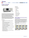
To measure power, connect the PA4000s measuring terminals in parallel with the
supply voltage and in series with the load current as shown below.
WARNING. To avoid injury always use good quality safety cables as supplied and
check that they are not damaged before use.
4
PA4000 Power Analyzer
Getting started
Connect the AC supply live to the Vhi (1) terminal
Connect the AC supply neutral to the Vlo (2) terminal
Connect the load neutral to either the 30 A Ahi (4) or 1 A A1a (6) terminal
Connect the supply neutral to the Alo (5) terminal
For plug-connected single phase products, the simplest and safest way to make a
connection to the product under test is to use a Tektronix Break Out Box. This
provides a line socket for connection of the product and 4 x 4 mm sockets for
direct connection to the PA4000 terminals as described above.
PA4000 Power Analyzer
5
Getting started
Default measurements
Switch on the supply to the load and the PA4000 is now ready to make
measurements. Note that it is not necessary to switch the PA4000 either off or
on when the load is being connected.
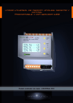
The default display shows up to 4 columns of results (one for each channel).
The display can be broken down into columns and rows. Each column is one
of 4 colors. The color represents which group the results in the column belong
to. There can be many different columns within a group. In a single-phase
application, there may only be one column of results per group. If the minimum
and maximum hold columns were added, then this would expand the number
of columns to 3.
Within a group, the result name is listed in the group color on the left of the group.
All the results with the group are always shown in the same order. The results
are shown on separate rows.
6
PA4000 Power Analyzer
Getting started
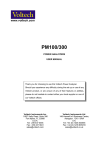
In default mode, each column represents one channel of the instrument, and each
channel is contained with a different group. Each group is configured as a wiring
setup, for example: 1 phase, 2 wire. Each row clearly shows the measurement
type ‘Vrms’, the measured value, ‘248.4’ and the measurement units, ‘V’. Normal
engineering notation is used to describe units, e.g. mV = milli-volts (10-3) and
MV = mega-volts (10+6).
Navigating the results screen
To scroll through the measurement rows, use the top two soft keys for scrolling
and paging up, and use the bottom two keys for scrolling and paging down:
PageUp
Row Up
Row Down
Page Down
To view the results in a larger size, the [ZOOM] key to the left of the display can
be used. It will cycle through 3 different zoom levels, which are:
4 columns of 12 results per column
2 columns of 6 results per column
1 column of 3 results per column
If there are more columns to view than can be displayed on the screen at one time
(for example: 6 columns of results in 4 column mode), the left and right arrow
keys to the left of the display can be used.
PA4000 Power Analyzer
7
Getting started
The PA4000 has the option of fixed or auto ranging. Default is auto range. If you
choose a fixed range, or the peak of the input signal it larger than the range, then
an over range condition will occur. This will be indicated on the results screen
by all the results in the over ranged channel flashing on and off. In addition, the
“Vrms” and / or “Arms” will flash to indicate whether the over range is on either
the voltage channel, the current channel, or both.
Navigating the menu system
The menu system provides complete access to all settings of the PA4000. To
access the menu system, press the yellow [MENU] key.
To return to the measurement display at any time, simply press the [MENU]
key again or press the [RESULT] key.
With the menu system active, the 5 soft keys to the right of the display may be
used to navigate and select options. A list of the menu keys can be found in the
soft key section of the manual. (See page 21, Soft keys.)
If the menu you are in displays a group or channel name, this means that the
setting is only for the displayed group or channel. To move to another group or
channel, use the left and right arrow keys.
Example: Choosing
measurements to display
One of the first tasks that a user may want to carry out is change the list of
measurements that are displayed.
To choose the measurements on the display:
1. Press [MENU] (to show the menu)
to see the list of Measurements. Measurements with a
2. Press
displayed in the order shown.
will be
3. Use the
and
keys to select a measurement to display and press
enable it to be displayed.
to
4. If you want to change the order in which a measurement is shown, first select
the measurement you want to move and then press . The selection bar
will turn red.
and
to move the measurement and then press
5. Use
new position.
To remove a selected measurement, select it and press
8
to accept the
.
PA4000 Power Analyzer
Getting started
Hint:
To restore the default list, see the User Configuration Menu. (See page 57, User
configuration.)
NOTE. Depending on the mode selected, some measurements will not be
selectable. (See page 40, Modes.) More details on selecting measurements are
available. (See page 33, Measurements.)
On screen help
Throughout the menu system on screen help is available to provide the user with
summarized help on the subject at hand. As an example, press the [MENU]
button and then press the [HELP] button and help on the main menu will be
displayed. Press the [HELP] button again to remove the help and return back
to the previous screen.
As the user tunnels through the menu system and requires help on a particular
screen, simply press the [HELP] button to get a brief summary of help on that
subject. Help does not exist on every screen and at every level therefore if the
[HELP] button is pressed without any help showing then there is no help available
at this level.
PA4000 Power Analyzer
9
Getting started
10
PA4000 Power Analyzer
Front panel operation
Front panel layout
1. Quick View buttons
2. Easy-to-reach USB connection for memory devices (optional Ethernet / USB
card is required)
3. 640 x 480 TFT display
4. 5 soft keys
5. Operational and Alphabet buttons
6. Number and Equation buttons
7. Front mounted on / off switch.
Quick view buttons
To the left of the display are the quick view buttons. These allow easy access
to various different displays.
The first 7 keys change the display screen to show different information:
[RESULT] - Displays the normal results screen
[WAVE] - Displays waveforms
[BAR] - Display harmonics bar chart
[INTEG.] - Displays integrator waveforms
[VECTOR] - Displays a vector diagram
[MATH] - Displays the math results as configured from the math menu
[SETUP] - Displays a screen showing the current configuration of the unit
Pressing any one of these keys will change the display to the appropriate display.
Pressing it again will have no effect.
PA4000 Power Analyzer
11
Front panel operation
At the bottom there is a [ZOOM] key, and left and right arrow keys.
The zoom key will change the number of results displayed on the screen. It will
go from 4 columns, to 2 columns and then to 1 column. Pressing again will return
the display to 4 columns.
The left and right arrow keys will move the results left and right to enable the
user to see more results (there can be up to 15 columns of results). The left and
the right arrow keys are also used in other screens such as the menu screen for
changing groups or the waveform screen for moving the cursors.
Results screen
The results screen is the default, power on screen for the PA4000.
The results screen displays all the requested results.
The size / number of results on the screen can be control by using the ZOOM key.
The actual results displayed, along with the order in which they are displayed,
is controlled by the [MEASUREMENTS] menu. (See page 33, Measurements.)
Also, the number of harmonics displayed, the minimum and maximum hold
columns displayed, and the display of the SUM column are controlled using the
[MEASUREMENT CONFIGURATION] menu.(See page 33, Main menu.)
12
PA4000 Power Analyzer
Front panel operation
Waveform screen
The waveform key will show waveforms of the measured data in continuous
operating mode.
The waveform screen consists of two sections. At the top right of the display are
the Volts, Amps and Watts values for each of the channels in the group. The label
for the channel is color coded to match the waveform. (See page 50, Graphs and
waveforms.) Measurement are displayed even if the waveform is not.
Below these measurements is the actual waveform which is plotted out against an
x and y axis.
Waveforms can be viewed by pressing the [WAVE] button to the left of the
display. Waveforms for viewing can also be selected by pressing [MENU] and
selecting Graphing and Waveforms and then Waveforms followed by the actual
selection of Vrms, Arms, or Watts to display as a waveform.
Waveform selection is done on a per-group basis. This means that only signals
within a specified group can be displayed on the same waveform graph.
Changing the group is done by using both the left and right arrow keys to the
bottom left of the display. This will change both the group for waveform selection
and the waveforms displayed.
PA4000 Power Analyzer
13
Front panel operation
When drawing a waveform, the phase reference signal for the group is started
at the intersection of the X and Y axis. Choosing to display or not display the
reference waveform will not affect the position of the other waveforms. For
example, if channel 1 volts was the phase reference and channel 1 amps was 90
degrees lagging, but channel 1 volts was not displayed, then channel 1 amps
would still start at 90 degrees lagging.
For the x (time) axis, the range will be twice the period of the lowest frequency
signal being displayed, rounded up to time starting with 1, 2 or 5. For example, if
50 Hz were the lowest frequency, then twice the period would be 40 ms, and so
50 ms would be the time base. If there is no frequency measured on any of the
displayed waveforms (i.e. all DC) then 500 ms will be used for the time base.
For the y axis the range for all the channels being displayed of the same units
(Volts or Amps or Watts) is examined. The maximum range is the range used.
Barchart screen
The bar chart displays either Volts, Amps or Watts harmonic information in the
form of a bar chart.
The data used for the display is based on the harmonics setup for the group in
which the channel is in. All soft key actions are on a per-group basis. The left and
).
right hard arrow keys are used to change channel (
Harmonics do not need to be displayed as results for the bar chart to show
harmonics. If harmonics is never displayed, and never configured, then the bar
chart would be based on the default harmonic setup.
14
PA4000 Power Analyzer
Front panel operation
At the top of each graph are 2 readings. The first is the fundamental value, in the
measured units, and phase angle. The second result is the highlighted harmonic in
the same units as it would be displayed on the results screen (either percentage
or absolute as defined by the users setting for the group) and the phase angle.
The phase angle will be displayed irrespective of whether it is displayed on the
results screen.
Next to the 2 readings is text stating the group and the channel that the bar chart
reflects.
An individual harmonic can be selected by using the left and right arrow soft keys.
The selected harmonic will be yellow as opposed to green. The left and right
arrows will only change the selection of the harmonic with the active group. If the
display is only showing one bar chart, then using the selection is straightforward.
When the user then changes to the next channel using the left and right hard
keys, the harmonic selected will be based on possible changes when viewing
the previous channel.
For the x axis, the maximum number of harmonic values that can be displayed
is 50, even though there could be up to 400. The harmonic values displayed are
determined by the harmonic sequence and range for the appropriate group. For
example, if the unit has been configured to display odd and even harmonics up to
the 50th, then 50 harmonics will be displayed. If only odd harmonics up to the
19th, then 10 harmonics will be displayed.
If the number of harmonics to be displayed is less than 50, then they will be
spread across the allowed width of the graph. If the user has selected more than
50 harmonics to display, then the left and right arrow soft keys will be used to
scroll through the harmonics and the axis labels will be changed after the 50th
harmonic result has been reached.
A summary of the soft keys is detailed below:
Toggles the harmonics displayed between
Volts, Amps and then Watts, returning back
to Volts. Works on a per-group basis.
Changes the harmonic selected by one to
the right (higher order).
Changes the harmonic selected by one to
the left (lower order).
Jumps to the harmonics setup menu.
PA4000 Power Analyzer
15
Front panel operation
Integrator screen
The integrator screen allows you to display integrated results on a graph. (See
page 41, Integrator mode.) One of the following results can be displayed at any
one time:
1. Watt Hours
2. VA Hours
3. VAr Hours
4. Amp Hours
5. Watts Average
6. PF Average
7. Volts
8. Amps
9. Watts
10. Fundamental VA-Hours (VAHf)
11. Fundamental VAr-Hours (VArHf)
12. Correction VArs
As with the integrator itself, the results are displayed on a group-by-group basis.
This means that the maximum number of plot lines is 4, which will occur in
a 3p4w system with SUM results. There is the option of adding or removing
plot lines from the display within the constraints of the group. For example,
you could select to see the channel 1 result and the SUM result. There are two
reasons for allowing this selection. Firstly, in a balanced three-phase system, the
integrated readings for each channel will be very similar and so the plot lines will
be overlaid one on top of the other. This could lead to confusion. Secondly, again
in a balanced three phase system, if a channel and the SUM results are displayed
on the same graph, the channel plot will never come higher up the y axis than 1/3
way, at best. Removing the SUM result and rescaling the y axis) allows better
resolution for the channel plot.
At the top of the display is a reading for each channel in the group (including the
SUM channel). The reading is for the same result as is selected in the integrator
waveform setup screen to display on the screen i.e. if the plot is WHrs, then the
reading is WHrs.
The plot is always in the same color as the channel designator.
At any time while the integration graph is being displayed, pressing the left
or right arrow hard keys will change to group results. If only one group is in
integrator mode, then graph will not change.
Both the x and y axis are automatically scaled. For the y axis, the time will
change automatically as the integration time increases. This allows for the best
viewing of the graph.
16
PA4000 Power Analyzer
Front panel operation
Any time during integration, you change the plots by pressing the [INT] soft
key. This will take the user directly to the integrator waveform setup menu with
the appropriate group selected.
Vector screen
The vector diagram displays one of Volts, Amps or Volts and Amps harmonic
information in the form of a vector diagram.
Vectors will be displayed on a per group basis. The left and right hard keys to the
left of the display will be used to change the currently displayed group. The active
group is displayed in the top left corner in the appropriate group color.
The left and the right soft keys will be used to change the harmonic number
currently being displayed. The harmonics available for display will be the same
as the harmonics in the results screen. There are two differences. The first is
that if the results screen is configured to display magnitudes as a percentage of
the fundamental, the absolute magnitude will still be used. This will allow a true
comparison between the magnitudes of the selected harmonic for each channel in
the group. The second is that if the user has not enabled harmonics to display,
then the harmonic setup will still be used. This therefore provides a quick way to
view harmonic information without displaying harmonics.
The [V/A] top soft key toggles the display between displaying Volts vectors only,
Amps vectors only and both Volts and Amps vectors.
Each vector displayed is shown in a different color. There can be up to 6 vectors
displayed on the graph at one time. This would be a for a 3p4w configuration
showing Volts and Amps.
PA4000 Power Analyzer
17
Front panel operation
In addition to displaying a vector line, the magnitude and phase angle of the vector
are displayed to the right of the vector diagram. Both the voltage and current
information is shown even if the vector is not.
The magnitude is based on the maximum range for the group being displayed
(in auto range channels can be on different ranges). The ranges will not change
when the harmonic number is changed, allowing a visual comparison between
harmonic numbers.
A summary of the soft keys is detailed below:
Toggles the vectors displayed between Volts
only, Amps only and Volt and Amps together.
Works on a per-group basis.
Changes the harmonic vector displayed by
one to the right (higher order). Works on a
per-group basis.
Changes the harmonic vector displayed by one
to the left (lower order). Works on a per-group
basis.
No action.
Jumps to the harmonics setup menu. Jumps to
the appropriate group.
Math screen
18
The Math screen is used to display user configured values. These could simply
be a selection of desired values displayed on one easy-to-read screen, or basic
measurements mathematically manipulated to show a required a value.
PA4000 Power Analyzer
Front panel operation
Up to 30 math functions, labelled FN1 through FN30, can be defined. For each
function the following can be specified:
Name – User friendly name up to 10 characters. (Default is the same as the
label i.e. FN1). In the menus, the function label is always displayed alongside
the users name for the function.
Units – User friendly units such as W for Watts. (Default is blank). Scaling
such as u, m, k, M will be added to the unit as appropriate. Units will be up
to 4 characters.
Equation – The actual math formula, up to 100 characters.
For additional information see Math.(See page 52, Math.)
Setup screen
PA4000 Power Analyzer
The setup screens are accessed by pressing the [SETUP] button. There are two
screens. The first screen displays the current configuration of the channels and
groups, and also items such as blanking and comms settings.
19
Front panel operation
The second screen shows instrument configuration including information such as
when the unit was last verified and last adjusted, the serial number of the unit and
the firmware version, and information on the installed analog cards.
20
PA4000 Power Analyzer
Front panel operation
Soft keys
Soft keys are used to provide context sensitive functionality. Through the many
screens, common soft key images are used to provide common functionality.
The common soft keys are shown below. If the symbol on the key is grey, then
it means that you have reached the limit of that key. For example, if you are at
the top of the results, then the up arrow will be grey. Details on the specialized
soft keys are in the appropriate section of the manual.
Page up
Move up one result / menu line / help text line
No functionality
Move down one result / menu line / help text
line
Page down
Tunnel up to the previous menu
Tunnel down to the selected menu
Move the selected measurement up or down
in the list
Move selected measurement up one row
Move selected measurement down one row
Select highlighted item
PA4000 Power Analyzer
21
Front panel operation
Cancel
Save result
Delete one character to the left of the cursor
Clear the text entry
Operational and alphabetical buttons
To the right of the soft keys are the operational keys, which also function as a
way of entering alphabetical characters.
[MENUS] – Toggles the on screen menus on and off. The menu will always
come on at the top level.
[HELP] – Toggles on screen help that is context sensitive based on the current
display. Pressing any other key, other than configured soft keys, when help
is displayed, will have no effect. Pressing [HELP] again will remove the
help screen.
[MENU 1] / [ABC], [MENU 2] / [DEF] – These keys provide quick access
to a set menu. Pressing and holding either of these keys for 2 seconds while
displaying a menu will link the menu to the pressed key. For example, if
you press and hold [MENU 1] while the Voltage range menu is showing,
then pressing [MENU 1] while any other screen is showing will display the
Voltage range menu.
[PRINT] / [GHI] – Send the displayed results to the designated printer /
device which can be either a USB printer, an RS232 printer or a memory
stick. NOT YET IMPLEMENTED.
[DATA OUT (DATA DUMP)] / [JKL] – Pressing this key will start or stop a
data log. If data is being logged, then the LED under this key will be flashing.
[RESET / CLEAR] / [MNO] – The function of this key will be dependent on
the configuration of the instrument. It can clear minimum / maximum hold
results and reset the integrator.
[INTEG. RUN] / [PQRS] - Pressing this key will start or stop the integrator. If
the integrator is running, then the LED under this key will be flashing.
22
PA4000 Power Analyzer
Front panel operation
[HOLD] / [TUV] – If pressed, the results stop updating on the screen.
Pressing again lets the results change. If the display is held, then the red
LED below the [HOLD] key will be illuminated. If the integrator is running,
the values will still be accumulating.
[LOCAL] / [WXYZ] – Any time the instrument receives communications via
USB, GPIB, Ethernet or RS232, the front panel will be locked out. Pressing
the [LOCAL] key will return control to the front panel. When the front panel
is locked out, the yellow LED beneath the [LOCAL] key will be lit.
Each of the above keys also has an alternative function, which is highlighted in
blue. To access these functions, the [SHIFT] key has to be pressed. Basically this
will give access to letters for text entry within the menus. Each time the same
key is pressed the letter being entered will be changed in the order shown above
the key. If the key is not pressed for 1 second, or a different key is pressed, the
cursor will move to the next position.
Number and equation buttons
The main purpose of the numeric section of the keypad is for numeric and
equation entry. The keys are as follows:
[7] / [x] - Number seven or, with [SHIFT], multiply.
[8] / [-] - Number eight or, with [SHIFT], subtract.
[9] / [+] - Number nine or, with [SHIFT], add.
[4] / [/] - Number four or, with [SHIFT], divide.
[5] / [(] - Number five or, with [SHIFT], left parentheses.
[6] / [)] - Number six or, with [SHIFT], right parentheses.
[1] / [SIN()] - Number one or, with [SHIFT], SIN function.
[2] / [COS()] - Number two or, with [SHIFT], COSINE function.
[3] / [TAN()] - Number three or, with [SHIFT], TAN function.
[0] / [:] - Number zero or, with [SHIFT], a colon).
[.] / [SPACE] - Decimal point or, with [SHIFT], space.
[=] / [xy] - Equals or, with [SHIFT], X to the power Y.
[+/-] / [x2] - positive or negative or, with [SHIFT], x squared.
[ SHIFT ] - Enable the blue shift options on both the numeric and general keys.
[ENTER] / [√] - Enter or, with [SHIFT], square root.
PA4000 Power Analyzer
23
Front panel operation
Logging data to a memory device
The PA4000, can be used to log data to a USB flash drive. The unit will log all
selected measurements into a comma separated value (CSV) formatted file that is
stored on the connected USB flash drive. Results will be logged once per second.
Prior to enabling data logging, insert a USB flash drive into the USB host port on
the front of the PA4000. The rear port cannot be used for flash drives.
CAUTION. If the USB flash drive is removed while data logging is enabled, data
corruption will occur.
Logging data
To start data logging press the [DATA OUT (DATA DUMP)] key. The LED
beneath the key flashing every second will indicate data logging. To stop data
logging, press the [DATA OUT (DATA DUMP)] key. Once the LED goes off, the
drive is safe to remove.
Data storage and format
The data will be logged in a directory created by the PA4000 on the USB flash
drive. The directory structure created will contain the last five digits of the serial
number of the PA4000 used and the date at the start of data logging. The file name
will reflect the time at the start of data logging in 24 hr format and will have a
.CSV extension.
For example, if a PA4000 with the serial number 100010200001 begins data
logging on 31 December 2011 at 2:18:56 PM, the directory tree will be as shown
below.
Root Dir\ PA4000 \00001\11-12-31\14-18-56.csv
The first portion of the file will contain a header identifying the instrument used
by serial number and the time data logging began.
The second portion will contain information on the group configuration of the
PA4000. It will contain the group index, the name of the group, the number of
channels in the group, and the number of results returned for the group.
The third portion of the file will contain column headers for every measurement
currently selected. Subsequent columns will contain an indexed set of the
measurements currently selected, in the order displayed on the PA4000 screen.
An example of the data returned is shown below.
24
PA4000 Power Analyzer
Front panel operation
Math results are also returned when data logging. These will be after the channel
results. Only enabled math results will be returned. The column name will consist
of the function name and the units specified by the user.
For additional information, see USB Host(See page 99, USB host.)
PA4000 Power Analyzer
25
Connecting signals
Connecting signals
Input overview
WARNING. To avoid possible electric shock or personal injury:
· Do not touch connections, internal circuits or measuring devices that are not
connected to earth ground.
· Always adhere to the instructions regarding the sequence of connection(See
page 2, Connection sequence.)
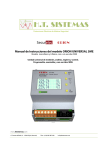
Signals are connected to the PA4000 on the rear of the PA4000. There are multiple
inputs for each analog card as shown below.
1. Voltage high connection
2. Voltage low connection
3. T1AH, 250 V fuse to protect the 1 A shunt
4. 30 A current high connection
26
PA4000 Power Analyzer
Connecting signals
5. Current low connection (common to both the 30 A and 1 A shunt)
6. 1 A current high connection
7. External shunt current input high
8. External shunt current input low
9. ±15 V supply for powering external transducers (optional)
Voltage
Voltages of up to 1000 Vrms may be connected directly to the black and yellow
4 mm VHI and VLO safety sockets at the rear of the PA4000.
Current
The PA4000 has two built-in current shunts. The shunt first allows currents of up
to 30 Arms, 200 A peak to be connected directly to the black and yellow 4 mm AHI
and ALO safety sockets at the rear of each measurement channel of the PA4000.
The second shunt allows up to 1 Arms, 5 A peak to be connected directly to the
blue 1A and blue safety sockets also on the rear of each measurement channel.
External current inputs
The external current inputs accept a voltage of up to ±3 V peak that is proportional
to the current being measured. This input allows a very wide range of external
current transducers to be connected, from low milliamp current shunts to
mega-Amp current transformers. For each type of transducer, the PA4000 may be
scaled to read the correct current. (See page 44, Inputs.)
The choice of current transducer will depend on:
The current being measured, including peaks and transients.
The accuracy required.
The bandwidth required: Unless the waveforms are purely sinusoidal, a
bandwidth in excess of the fundamental frequency will be required.
Whether there is DC current present.
Convenience of connection – that is, using a clamp-on current transformer,
with jaws that open, for quick connection in a fixed wiring loom.
The effect of the transducer on the circuit.
PA4000 Power Analyzer
27
Connecting signals
To connect a simple current transformer
To use a conventional current transformer (CT) like the Tektronix CL series (or any
other transducer with a current output), connect the normal AHI and ALO inputs
of the PA4000 to the outputs of the current transformer. Follow the manufacturers
instructions for the safe use and installation of the transducer. Depending on the
output level of the current transformer, you will need to choose between the 30 A
AHI input and the 1 A AHI input. The choice will be dependent on the dynamic
range of the output of the current transformer that you are expecting.
Normally the positive or HI output of the transducer will be marked with the
point of an arrow or a + symbol. Connect this terminal to the appropriate AHI
input of the PA4000.
Current scaling
A current transformer produces an output current that is proportional to the load
current being measured. For example, the Tektronix CL200 produces an output
current that is 1/100 of the current being measured.
To measure the correct current on the PA4000, use the scaling function of the
analyzer to scale, or multiply, the CT output current.
For example, the CL200 is a 100:1 CT. When measuring 100A, its output is 1A.
To scale this on the PA4000, a scale factor of 100 must be entered:
Press [MENU]
Select
‘Inputs’ and press
Select
‘Scaling’ and press
Select
‘Amps’ and press
Use the
key to clear the entry.
Type the new scale factor (100)
Press
Press [MENU] to return to the measurement display.
The PA4000 is now ready to make measurements using a CT.
28
PA4000 Power Analyzer
Connecting signals
To connect an external resistive shunt
Using a resistive shunt is a straightforward method of extending the current
measuring range of the PA4000. The shunt resistor is connected in series with the
load and the voltage across the shunt is directly proportional to current.
That voltage may be connected directly to the External Current Inputs of the
PA4000.
For example, a 1 milliohm shunt is used to measure 200 A rms.
1. Check that the voltage that will be generated is suitable for the PA4000
V = I x R (Ohm’s law)
Vshunt = I x Rshunt
Vshunt = 200 x 0.001 Ohms
Vshunt = 0.2 V
This is well within the 3 Vpk rating of the PA4000’s External Current Inputs
2. Connect the shunt in series with the load and to the EXT-HI and EXT-LO
inputs as shown.
Remove any connections to the normal ALO terminal!
WARNING. Connections to the normal AMPS terminals can have high voltage
on them.
To avoid errors and a risk of electric shock, remove all connections to ALO.
EXT-LO and ALO are connected inside the PA4000 and so connections to AHi,
ALo and A1A can have the same potential as EXT-LO.
For the best noise immunity EXT-LO should be connected directly to ALO.
3. Set up the PA4000 to measure current from the EXT-HI and EXT-LO
terminals. Press ’MENU’
Press [MENU]
PA4000 Power Analyzer
29
Connecting signals
Select
‘Inputs’ and press
Select
‘Shunts’ and press
Select
‘External’ and press
Press [MENU] to return to the measurement display.
4. Scale the measurement on the display.
The default scale is 1 V = 1 A.
In this example where R = 0.001 Ohms. The scaling factor is specified in
Amps per Volt, so in this case, the scaling factor is 1000.
To enter a scale factor for current:
Press [MENU]
Select
‘Inputs’ and press
Select
‘Scaling’ and press
Select
‘External Shunt’ and press
Use the
key to clear the entry.
Type the new scale factor (100)
Press
Press [MENU] to return to the measurement display.
The PA4000 is now ready to make measurements using an external shunt.
To connect a transducer with a voltage output
These transducers contain active circuits that help to improve performance at high
bandwidth. They may be of the ‘hall effect’ or Rogowski coil type.
The procedure is similar to that of installing an external shunt as described above.
1. Follow the manufacturer’s instructions for the safe use and installation of
the transducer.
2. Connect the voltage output to the EXT-HI and EXT-LO terminals of the
PA4000 channel as above.
3. Select ‘Inputs’ – ‘Shunts’ – ‘External’ as above.
Press [MENU]
30
Select
‘Inputs’ and press
Select
‘Shunts’ and press
Select
‘External’ and press
PA4000 Power Analyzer
Connecting signals
Press [MENU] to return to the measurement display.
4. Select and input a scale factor. These types of transducers are often rated in
terms of mV / amp. For example a transducer with an output of 100mV / amp
is the equivalent of a 100 milliohm external shunt resistor. To convert the rated
scaling from Volts per Amp to the desired Amps per Volt, invert the value.
Using the above example, 100 mV / Amps is equivalent to 10 Amps / Volt.
Press [MENU]
Select
‘Inputs’ and press
Select
‘Scaling’ and press
Select
‘External Shunt’ and press
Use the
key to clear the entry.
Type the new scale factor (such as 0.1)
Press
5. Press ‘MENU’ to return to the measurement display.
The PA4000 is now ready to make measurements using a current transducer with
a voltage output.
To connect a voltage transformer / transducer
The PA4000 may be used with a voltage transformer (VT) or other transducer to
extend its measuring range. Follow the manufacturer’s instructions for the safe
use and installation of the transducer.
The output of the transducer is connected to the normal VHI and VLO terminals.
Normally the positive or HI output of the transducer will be marked with the point
of an arrow or a + symbol. Connect this terminal to the VHI input of the PA4000.
Voltage scaling
PA4000 Power Analyzer
A voltage transformer (VT) produces a voltage output, which is proportional to
the voltage being measured.
31
Connecting signals
To measure the correct voltage on the PA4000, use the scale function of the
analyzer to scale, or multiply, the VT output current.
For example, when measuring with a 1000:1 VT a scale factor of 1000 must
be used.
Press [MENU]
Select
‘Inputs’ and press
Select
‘Scaling’ and press
Select
‘Volts’ and press
Use the
key to clear the entry.
Type the new scale factor (1000)
Press
Press MENU to return to the measurement display.
The PA4000 is now ready to make measurements using a VT.
Power for external transducers
The PA4000 can have an optional ±15 V power supply for the purpose of
providing power to external transducers. The supply is capable of supplying
250 mA per rail on each analog card (250 mA on +15 V and 250 mA on -15 V).
The connector is conveniently placed next to the inputs on each analog.
If the ±15 V supply option is purchased, then 4 mating connectors (Tektronix part
number 56-598) will be provided to aid in making a connection. These connectors
are Wago 231-303/026-000.
32
PA4000 Power Analyzer
The menu system
The menu system
Navigation
The PA4000’s menu is a powerful yet easy-to-use system for control of the
analyzer. See the Quick Start section of this manual for an overview of how to
access and use the menu system. (See page 8, Navigating the menu system.)
For help at any time while using the PA4000 press the HELP key at any time.
Menu items
To switch the display of the menu system off or on, press the ‘MENU’ key at
any time.
Main menu
To select a menu, press the MENU key.
Measurements
Default: Vrms, Arms, Watt, VA, PF, and Freq.
The user can set the order in which the measurements appear on the screen. This
is on a per-group basis. The measurements, on a group-by-group basis, can be
displayed in any order, including harmonics. However, harmonic results will
always be displayed as a block i.e. all the Voltage harmonics will be displayed
as a continuous block based on the parameters set.
A normal measurement screen is shown below:
PA4000 Power Analyzer
33
The menu system
On the measurements screen you will both be able to select a measurement to be
displayed as a result and also change the order in which the results are displayed.
When you enter the measurement screen you will have the following soft keys
available:
Tunnel Up
Selection Up or top of list
Move Measurement
34
PA4000 Power Analyzer
The menu system
Selection down or bottom of list
Select measurement to be a result on the
screen or de-select measurement
or
To navigate to a desired result, use the up and down arrow soft keys. The current
selection will be shown by the measurement highlighted in blue.
If a result is selected, then it will have a green check mark at the right hand edge
of the list. If it is not selected, then there will be no check mark.
The results screen shows all the selected results, in the order in which they appear
in the measurement list, remembering that the list only applies to the group
selected.
NOTE. Unless the group is in Integrator mode, integration measurements cannot
be selected. These measurements are:
Hours
Watt-Hours
VA-Hours
VAr-Hours
Amp-Hours
Average Watts
Average PF
Corrected VAr
Fundamental VA-Hours (VAHf)
Fundamental VAr-Hours (VArHf)
If you need to change the order of the results, then you should navigate to the
desired result and then click the “Move Measurement” soft key. When the move
measurement key is pressed, the highlight bar will change from blue to red.
The soft keys will then change as shown below:
PA4000 Power Analyzer
35
The menu system
Tunnel Up. The move is cancelled, and the
user will return to the main menu screen.
Move selected measurement up (gray if at the
top of the list already).
Cancel the move, and put the measurement
back where it was before the move was started.
Move selected measurement down (gray if at
the bottom of the list already).
Place the measurement in the selected
position. The soft keys will change back to the
standard measurement screen keys.
An example of a measurement being moved is shown below:
36
PA4000 Power Analyzer
The menu system
Measurements configuration
The measurement configuration menu contains menus to set up Volts and
Amps harmonics as well as Volts and Amps THD, DF and TIF readings.
These measurements are selected in the measurement menu. In addition, the
measurement configuration menus allow the selection of the SUM channel
column and the minimum and maximum hold columns.
The top-level menu consists of the following:
Harmonics Setup
Distortion Setup
Minimum Hold Column
Maximum Hold Column
SUM Column
Harmonics setup
Under the harmonics menu item there are separate voltage, current and Watts
menus that allow the setting of the following:
Harmonic Sequence - Odd and even or odd harmonic only (default Odd and
even).
Range – 1 to 100 (default 7)
Format – Absolute or percentage of fundamental (default Absolute)
Display Phase Angle – On or off (default On) (Volts and Amps only)
The selection of harmonics results to display has no impact on the harmonic data
used in distortion calculations.
Please see the User Configuration section of this manual about update speed. (See
page 57, User configuration.) The instrument is not able to calculate and display
100 harmonics on V, A and Watts every 100 ms.
Distortion setup
Under the Distortion Setup line item there will be separate menus for Vdf
(Distortion Factor), Vthd (Total Harmonic Distortion), Vtif (Telephone Influence
Factor), Adf, Athd and Atif.
Distortion Factor. The Distortion Factor formula (previously called the Difference
Formula) includes the effects of high frequency and noise. This equation only
produces a valid number if the RMS is not less than the fundamental. If the
fundamental is larger than the RMS the display shows ‘—-‘.
The equations are:
and
PA4000 Power Analyzer
37
The menu system
The reference value can be either the fundamental reading or the rms reading. The
default reference is the fundamental value.
Total Harmonic Distortion (THD). THD (Total Harmonic Distortion) is a measure
of the distortion of a waveform.
Under the V and A Total Harmonic Distortion factor (THD) measurement menus
is the ability to set the following parameters:
Harmonic Reference – Fundamental or RMS (default Fundamental).
Harmonic Sequence - Odd and even or odd harmonic only (default is odd
and even).
Range – 2 to 100 (default 7). This is the last harmonic used in the calculation.
If odd only harmonics are specified and Range is set to an even number, then
the preceding harmonic will be the last one used.
Harmonic Zero – Exclude or Include (default Exclude)
For the distortion settings and harmonics setting, the values will be remembered
whether the actual displaying of the reading is turned on or off. For example, if
the number of harmonics to be displayed is changed from 7 to 13, turning off and
then on again the display of voltage harmonics will not affect this setting.
The formula for voltage and current THD are:
and
The Total Harmonic Distortion formula (previously called the series formula) will
produce more accurate results for harmonic noise when the THD is less than 5%.
When selecting the THD formula, it is important to set the MAX HARMONICS
setting to an appropriately large number to get valid results. The higher the
harmonic count the more accurate the calculation.
Telephone Influence Factor (TIF). TIF stands for telephone influence factor and is
a THD measurement weighted at frequencies within the bandwidth of a normal
telephone circuit. It is a measure of how the voltage or current distortion in
electrical power circuits might interfere with adjacent telephone circuits. TIF
measurements are a requirement of standards such as ANSI C50.13 "Rotating
Electrical Machinery - Cylindrical-Rotor Synchronous Generators" and are most
often used on standby power generators and UPS. The harmonics included in a
TIF measurement are from 1 to 73 odd and even.
The formula for voltage and current TIF are:
38
PA4000 Power Analyzer
The menu system
Default reference = Fundamental
and
The weighting factors (K) are:
Harm
kn
Harm
kn
Harm
kn
1
0.5
21
6050
41
10340
3
30
23
6370
43
10600
5
225
24
6650
47
10210
6
400
25
6680
49
9820
7
650
27
6970
50
9670
9
1320
29
7320
53
8740
11
2260
30
7570
55
8090
12
2760
31
7820
59
6730
13
3360
33
8830
61
6130
15
4350
35
8830
65
4400
17
5100
36
9080
67
3700
18
5400
37
9330
71
2750
19
5630
39
9840
73
2190
Minimum and maximum
hold columns
For maximum and minimum hold menus, the columns can independently be
enabled or disabled. To reset the values shown in the columns, press the [RESET]
key. Also, each time either the minimum or maximum hold column is enabled,
the values for both columns are reset.
SUM results column
SUM results will appear after the last channel in the group (and after that channels
max and min results if necessary). Sum Max will appear to the right of the SUM
results and Sum Min will appear to the left of the Sum results as appropriate.
SUM results are available in all wiring configurations except 1 phase, 2 wire
(1P2W). (See page 44, Wiring.)
PA4000 Power Analyzer
39
The menu system
Modes
Default: Normal
Modes are used to set up the instrument in specific way to allow certain types of
measurements. These specific modes provide all necessary filtering and unique
configuration parameters necessary to measure specific signals found in certain
applications.
Modes are applied on a group basis. For example, in light ballast applications,
group A could be in normal mode measuring the input power and group B could
be in ballast mode measuring the output power.
Currently there are three available modes. These are:
Normal - This mode is used for most power measurements where signals are
uniform and there are no special measurement methods required.
Ballast - This mode is designed to configure the group to make measurements
on the complex ballast output modulated waveforms.
Standby Power- This mode integrates the Watts, Amps, VA and PF readings
over a user-specified measurement period. This is a requirement of many
standby power standards.
It is often necessary to force the instrument in to a certain way of operating
when a particular mode is selected. An example is forcing high bandwidth
when ballast mode is selected. In these cases two things will happen:
a. Reverting back to normal mode will restore any changed settings
b. When a setting is forced, it cannot be changed by the operator while the
PA4000 is in the non-normal mode
Normal mode
In normal mode, there are no special measurement methods used. Normal mode is
suitable for most power applications and is the default mode.
Ballast mode
In modern electronic lighting ballasts, it is often difficult to make accurate
measurements due to the fact that the output signals are high frequency waveforms
that are heavily modulated by the power frequency. Ballast mode provides a way
of locking the measurement period to the power frequency.
After selecting ballast mode you need to set up the fundamental frequency at which
power will be transmitted. This is typically 50, 60 or 400Hz. The setup screen can
be found under the Modes –> Setup Modes—> Ballast Setup. The analyzer will
then use this to adjust the measurement window to fit the specified frequency.
The frequency returned by the instrument is therefore not the fundamental power
frequency, but instead the ballast switching frequency. This is also the frequency
used for harmonic analysis.
40
PA4000 Power Analyzer
The menu system
When ballast mode is selected, the frequency range is set to “>10Hz” and the
bandwidth is set to “High” for the group. These setting are locked out in ballast
mode and, upon the return to normal mode, they are restored.
Standby power mode
Driven by consumer demand and energy efficiency legislation, there is an
ever-increasing need to measure power consumption of product while they are
in standby mode. One of the most widely used standards for measurement is
IEC 62301. Part of this standard requires the measurement of power over a
prolonged period of time without missing any short duration power events. The
PA4000 standby power mode provides continuous sampling of voltage and current
to produce an accurate Watts measurement over the user specified period.
In standby mode, you must specify the integration window in seconds. Watts,
Amps, Power Factor and VA will then be integrated over the specified period. All
other results will be updated at the normal user specified update rate.
The integration period is dependent on the combination of the specified window
and the unit update rate. (See page 56, Update rate.) This is because the results
will be integrated over an exact multiple of the update rate. For example, if the
update rate is 0.5 seconds (default) then the integration period will always be
exactly as specified. However, if an update rate of 0.4 seconds is requested, then
integration period will switch between 1.2 seconds and 0.8 seconds.
For the most accurate measurements it is recommended that the ranges are fixed
during the measurement period. (See page 47, Fixed/Auto ranging.)
Integrator mode
Integrator mode is used to provide measurements for determining energy
consumption. In addition, for certain parameters, average values are also available.
The required measurements are selected in the Measurements menu. (See page 33,
Measurements.) The integrator measurements are:
Hours
Watt-Hours
VA-Hours
VAr-Hours
Amp-Hours
Average Watts
Average PF
Corrected VAr
Fundamental VA-Hours (VAHf)
Fundamental VAr-Hours (VArHf)
PA4000 Power Analyzer
41
The menu system
These measurements are on a per-group basis. The measurements can only be
selected and displayed when the group is in integrator mode. If an integrator
measurement is selected and the mode is changed to a non-integrator mode, then
the measurements will show as not being selected. Changing the group mode back
to integrator mode will restore the selection previously used.
Configuring integrator mode. After selecting integrator mode, and the
measurements to display, there are a number of options provided for starting
and stopping the integrator. These are set up in the Modes -> Setup Mode - >
Integrator Setup section of the menus.
Start method. Default: Manual
Manual starting: Manual starting of integration is triggered pressing the [INTEG
RUN] key on the front panel. Pressing this key will start the integrator running
on all groups that are configured as integrator mode with a manual start and are
currently not running. The LED under the key will be turned on.
Clock Starting: In clock starting mode, you can set the time and date of when you
want the integrator to start for the group. The time and date are entered in the
user’s specified format (see System configuration -> Clock menus). (See page 56,
Clock.) Once the desired time has been reached, integration will start.
If, when the time / date combination in the clock start method is set, the time is
before the current time and date, then integration will not start. Integration will
only start when at least one screen update has occurred before the start time.
Level Starting: In this start method, you have the ability to start integrating
when a certain parameter either goes above or below a user entered level. You
can configure the following:
Select the channel, 1 through 4
Select the signal parameter from that channel. This can be any parameter
with the exception of integrated values and harmonic values (including
fundamentals)
Select the level threshold to be monitored. This is the actual parameter value
in decimal. For example for 80 mA enter 0.08, 80 V enter 80.
Select whether the signal should be greater than or equal to the level or less
than or equal to the level.
A trigger channel 1-4 may be selected from any group and used as a trigger
for integration. The trigger measurement does not have to be in the channel or
group you are then integrating.
Once the conditions have been met, integration will start.
Stopping integration. The integration of a group can be stopped either manually
or after a certain period of time. If the duration for the group is set to zero, then
42
PA4000 Power Analyzer
The menu system
the integration will only stop if the [INTEG. RUN] key is pressed. The duration is
entered in minutes as a floating point number from 0.0 to 10,000.
Integration is manually stopped by pressing the [INTEG. RUN] key. This will
stop integration on all groups that are in integrator mode with the integrator
running where the duration is set to zero. The LED under the key will be turned
off if there is no more integration going on within any group.
Resetting integration values. The [RESET/CLEAR] key will reset the integration
values to zero for all stopped groups. It will not have any effect on groups that
are running integration.
Correction VAr (CVArs). This parameter displays the values of VArs required to
correct the average power factor to a target power factor. The target power factor
is entered under the integrator setup screen under CVArs Power Factor.
The correction will calculate the necessary VArs to provide a phase shift to reach a
target power factor. It does not compute the total VArs (e.g. if a poor power factor
is completely due to distortion, no amount of phase lead or lag will improve it).
PWM Motor mode
PWM Motor mode has been designed to overcome the difficulties associated with
making measurements on the complex waveforms found on the motor drive.
High frequency sampling is combined with digital filtering to reject the carrier
frequency and extract the motor frequency while still using pre-filtered data for
power parameters.
After selecting PWM mode, you should then select the frequency range of the
motor frequency (not the carrier frequency) under the Inputs -> Frequency Source
-> Frequency Range menu.
When in PWM mode, the maximum motor frequency is limited to 900 Hz, even if
a higher frequency range is selected.
The selection of the frequency range will impact the rate at which results are
returned. The update rate for all the channels is set in the System Configuration
menu. (See page 56, Update rate.) However, if the frequency range in PWM
mode is set to either 1 – 100 Hz or 0.1 – 10 Hz, then the rate at which results are
returned for that group is altered per the table below:
PA4000 Power Analyzer
Update rate
(seconds)
>10 Hz
<900 Hz
1 – 100 Hz
0.1 Hz – 10 Hz
0.2
0.4
2.4
20.2
0.3
0.3
2.4
20.4
0.4
0.4
2.4
20.4
0.5
0.5
2.5
20.5
0.6
0.6
2.4
20.4
0.7
0.7
2.1
20.3
0.8
0.8
2.4
20.8
43
The menu system
Update rate
(seconds)
>10 Hz
<900 Hz
1 – 100 Hz
0.1 Hz – 10 Hz
0.9
0.9
2.7
20.7
1.0
1.0
3.0
21.0
1.1
1.1
2.2
20.9
1.2
1.2
2.4
20.4
1.3
1.3
2.6
20.8
1.4
1.4
2.8
21.0
1.5
1.5
3.0
21.0
1.6
1.6
3.2
20.8
1.7
1.7
3.4
20.4
1.8
1.8
3.6
21.6
1.9
1.9
3.8
20.9
2.0
2.0
4.0
22.0
Results from channels not in PWM Motor mode will be returned at the specified
rate.
Inputs
This menu may be used to set up the physical inputs of the PA4000. For normal
operation, with the exception of the shunt selection, it is not necessary to change
these settings from default.
Wiring
For multiphase measurements, a number of channels can be assigned to a group
allowing precise frequency and phase analysis of the multiphase signals. The
frequency of the first channel in the group is used as the fundamental frequency
for all channels in the group, and all phase measurements are relative to the phase
reference (Voltage by default) of the first channel in the group.
Below is a diagram showing how each channel would be connected for each
different wiring mode.
44
PA4000 Power Analyzer
The menu system
Single-phase, two-wire and DC
measurements. Select 1 phase, 2
wire mode.
Single-phase, three-wire. Select 1
phase, 3 wire.
Three-phase, three-wire
(2 Wattmeter method). Select
3 phase, 3 wire.
PA4000 Power Analyzer
45
The menu system
Three-phase, three-wire
(3 Wattmeter method). Select
3 phase, 4 wire.
Three-phase, four-wire (3 Wattmeter
method). Select 3 phase, 4 wire.
Depending on the wiring configuration, not all groups will be available. For
example, if wiring is 1p2w for each channel, then the 4 channels will correspond
to the 4 groups. If the wiring is 1p3w for group A, then channels 1 and 2 will be
in-group A. This will leave channels 2 and 3 for a maximum of groups B and C.
Group D cannot exist in this condition.
Group A wiring takes priority, followed by groups B, C and then D. For example,
starting from a 1p2w configuration for all groups, if group A is set to 1p3w, then
group D can’t be set to anything and therefore group C will be 1p2w only. Group
B will have the choice of 1p2, 1p3w and 3p3w.
Ranges
The ranges are set on a group basis. The ranges will be as follows:
Range #
Volts
30 A shunt
1 A shunt
Ext. shunt
3
2V
0.2 A
0.005 A
0.003 V
4
5V
0.5 A
0.0125 A
0.00375 V
5
10 V
1A
0.025 A
0.015 V
6
20 V
2A
0.05 A
0.03 V
7
50 V
5A
0.125 A
0.0375 V
8
100 V
10 A
0.25 A
0.15 V
9
200 V
20 A
0.5 A
0.3 V
10
500 V
50 A
1.25 A
0.375 V
11
1000 V
100 A
2.5 A
1.5 V
12
2000 V
200 A
5A
3V
Auto
46
PA4000 Power Analyzer
The menu system
Fixed/Auto ranging
Default: auto range
For most measurements, auto-ranging is the best choice. Choosing a fixed range
may be useful if the voltage or current is changing continuously or has large peaks
that make the analyzer spend excessive time changing range.
If you choose a fixed range, or the peak of the input signal is larger than the range,
then an over range condition will occur. This will be indicated on the screen by
all the results in the over ranged channel flashing on and off. In addition, the
“Vrms” and/or “Arms” will flash to indicate whether the over-range is on either
the voltage channel, the current channel, or both.
Shunts
Default: 30A shunt
The PA4000 has 3 different current inputs, or shunts. They are:
30A shunt – Used for normal current measurement in the range of 100mA
to 30Arms (200Apk). This selection uses the yellow Ahi and the black Alo
4mm sockets.
1A shunt – Used for small current measurements such as those found in
standby power applications in the range of 2.5mA to 1A. This selection uses
the blue A1A and the black Alo 4mm sockets.
External shunt – Used for the measurement of current where an external
transducer is used and the transducer has a voltage output. The blue and black
2mm sockets on each analog card are used for the external shunt inputs.
WARNING. Passing an rms current of greater than 15 A through the 30 A shunt,
with the selected shunt set to either 1 A or external, can cause damage to the
30 A shunt.
See the Chapter ‘Using External Voltage and Current Transducers’ for further
information.
Frequency source
There are 3 selections under the Frequency Source menu. They are:
Source
Phase Reference
Frequency Range
Source. Default: Voltage
Many measurements (including rms volts, amps and watts) are based on
calculations that are dependent on the correct fundamental frequency being
determined by the analyzer.
PA4000 Power Analyzer
47
The menu system
The PA4000 uses proprietary techniques to determine frequency that eliminate the
problems created by noise when simple zero-crossing techniques are used.
It is therefore not normally necessary to adjust the settings from the default of
voltage.
Volts. Volts is the default frequency source and is suitable for most applications.
Amps. Amps may be selected if the voltage waveform is heavily distorted, but
the current is not. The waveforms at the output of a PWM motor drive are an
example of this.
External Frequency 1 / 2. On the rear of the PA4000 there are 2 counter inputs
on the Auxiliary Inputs / Outputs connector. Either of these can be used as an
external frequency source for signals where there is too much noise on the voltage
and current waveforms. Apply a TTL compatible square wave to the external
input at the required frequency.
Phase Reference. Default:
Volts This is the zero reference for phase angle measurements in each group.
Volts. Phase is calculated with respect to the voltage signal on the first channel
in the group.
Amps. Phase is calculated with respect to the current signal on the first channel
in the group.
External Frequency 1 / 2. Phase is calculated with respect to the external input
signal.
Frequency range. Default: 10 Hz - 50 kHz
There are 4 frequency ranges:
10 Hz - 50 kHz
>10 Hz
1 - 100 Hz (PWM Motor mode only)
0.1 - 10 Hz (PWM Motor mode only)
For measurements where the fundamental is below 50 kHz, the range of “>10 Hz
and <50 kHz” is recommended, especially at low signal levels.
If the fundamental frequency is greater than >50 kHz, then the range should be
set to “>10 Hz”.
1 - 100 Hz and 0.1 - 10 Hz are used in PWM motor mode.
Bandwidth
48
Default: High
PA4000 Power Analyzer
The menu system
The bandwidth is set on a per-group basis. Setting the bandwidth will apply a
10 kHz, two-pole filter to the voltage and current channel inputs.
WARNING. If low bandwidth mode is selected, damage can be caused to the 30 A
shunt if the current applied has a fundamental frequency of greater than 10 kHz
and an rms value of greater than 20 Arms.
Scaling
Scaling is used to adjust the scaled output of transducers such as current
transformers so that the true measured current is displayed on the PA4000. The
scaling factor will affect every measured value related to the input to which it is
applied.
Maximum scale factor: 100000
Minimum scale factor: 0.00001
Volts scaling. Default: 1.0000
Enter the scale factor of the transducer. For example, a 100:1 voltage transformer
is used to measure 15 kV. The output of the transformer is 15000 / 100 = 150 V.
Enter the scale factor 100, and the PA4000 will display 15,000 V.
Amps scaling. Default: 1.0000
Enter the scale factor of the transducer being used. For example, the Tektronix
CL1200 produces 1 amp for every 1000 amps flowing in the opening of the CL.
It is a 1000:1 current transformer. Enter the scale factor 1000 and the PA4000
will display the correct current.
Scale factor = Transducer Input Current / Transducer Output Current
External shunt scaling. Default: 1.000
This scaling is applied to the current measurement channel voltage inputs. This is
used for current transducers that have a voltage output. These include Hall-effect
transducers as well as simple resistive shunts.
The scaling factor is expressed in Amps (read) per Volt (applied).
The default value is 1. This means that with 1 Vrms applied, the current channel
will read 1 Arms.
An example would be a clamp-on Hall-effect current transducer measures up to
100 A. It has a voltage output of 10 mV per Amp, which is equivalent to 100 Amps
per Volt. Enter ‘100.00’ and the PA4000 will display the correct system current.
External phase
compensation
PA4000 Power Analyzer
Not yet implemented.
49
The menu system
Analog inputs
Default: ±10 V range
The PA4000 has 4 analog inputs on the rear of the instrument. Each of the
4 inputs can used to measure signal from a device such as a torque sensor. Each
of the four inputs has 2 different ranges. The ranges are ±10 V and ±1 V. Each
input is sampled every millisecond the average value over the update rate of
the instrument.
Analog inputs are made available to the MATH setup. They can be incorporated
into the MATH formula and displayed on the MATH screen. (See page 52, Math.)
Graphs and waveforms
The PA4000 provides 4 graphical ways of displaying data:
Waveforms
Harmonic bar chart
Vector diagram
Integrator graphing
There are menu options for both waveforms and integrator graphing, bar charts
and vector diagrams. (See page 11, Quick view buttons.)
Waveforms
The waveform menu allows you to select which waveforms to display on the
waveform screen. For each group, you can select any voltage, current or Watts
waveform for each channel in the group for displaying on the waveform graph.
(See page 11, Quick view buttons.)
To change groups use the left and right arrow keys at the bottom left of the display.
Integrator parameters
The Integrator parameter menu allows you to select one parameter to display on
the integrator graphing screen from the list of available integrator parameters
below:
Watt Hours
VA Hours
VAr Hours
Amp Hours
Watts Average
PF Average
Volts
Amps
50
PA4000 Power Analyzer
The menu system
Watts
Fundamental VA-Hours (VAHf)
Fundamental VAr-Hours (VArHf)
Correction VAr
For each waveform selected, there is a choice on the graph menu to turn on or off
the selected parameter for each channel in the group.
Integrator graphing parameters are set on a per-group basis. To change groups use
the left and right arrow keys at the bottom left of the display.
For more information on setting up the integrator, (See page 41.). For more
information on displaying the integrator waveforms, (See page 16.)
Interfaces
This menu may be used to set up the interfaces of the PA4000.
RS232 baud rate
Default: 38400
9600, 19200 and 38400 (default) are available.
The PA4000 uses hardware handshaking (RTS / CTS) with no parity, 8 data bits
and 1stop bit (N,8,1).
The RS232 baud rate is unchanged after a “*RST” or “:DVC” command.
GPIB Address
Default: 6
Enter the GPIB address.
Default address is 6. The address is unchanged after a “*RST” or “:DVC”
command.
Printing
Ethernet Configure
Not yet implemented.
The PA4000 offers Ethernet communications through an Ethernet port using
TCP/IP.
The Ethernet port will make a TCP/IP connection on port 5025. Port 5025 is
designated by the Internet Assigned Numbers Authority (IANA) to be a SCPI port.
Use the IP Selection Method menu, to opt for a dynamically assigned IP address,
by selecting “Set IP using DHCP”, or a fixed/static IP address by selecting “Fix
IP Address”.
To view the current IP settings, press the [SETUP] key.
PA4000 Power Analyzer
51
The menu system
To configure the static IP address, choose “Static IP Settings” in the Ethernet
Setup menu. This allows entry of the IP address, the subnet mask and the default
gateway. After entering the relevant data press the OK button, in each menu,
to apply.
For basic communication needs via TCP/IP the user can try the Agilent
Connection Expert contained in the Agilent IO Libraries Suite 15.0.
The Ethernet mode (Static/DHCP), IP address, default gateway and subnet mask
are unchanged after a “*RST” or “:DVC” command.
Datalog
Future implementation.
Math
The math results are displayed on a different results screen from the other results.
This improves the ability to view math results. Normal measurement parameters
can be displayed on the math results screen. They just have to be specified in a
formula. (See page 18, Math screen.)
The user is able to set the values of up to 30 math functions, labelled FN1 through
FN30. For each function you can specify the following:
Name – User-friendly name up to 10 characters. (Default is the same as the
label i.e. FN1). In the menus, the function label is always displayed alongside
the users name for the function.
Units – User friendly units such as W for Watts. (Default is blank). Scaling
such as u, m, k, M will be added to the unit as appropriate. Units are up to
4 characters.
Equation – The actual math formula, up to 100 characters.
Example: W = 21.49, VA = 46.45
Name = “PF”
Units = “PF”
Equation = “CH1:W / CH1:VA” W = 21.49 and VA = 46.45
To select this equation for viewing go to the MATH menu list showing FN1
– FN30 and apply the green tick to the one you wish to view. Next press
the [MATH] hard key to display your equation, the math’s results display
will show “PF 463.27 mPF”
Example: CH1:W = 21.49, CH2:W = 53.79
Name = “EFFICIENCY”
52
PA4000 Power Analyzer
The menu system
Units = “W”
Equation = “CH1:W / CH2:W”
To select this equation for viewing go to the MATH menu list showing FN1 –
FN30 and apply the green tick to the one you wish to view. Next press the
[MATH] hard key to display your equation, the math’s results display will
show “EFFICIENCY 399.95 mW “
You can specify any channel or group parameter listed below in addition to the
voltage input on each of the 4 analog inputs.
Valid character are A-Z, 0-9,., x, -, +, /, (, ), :, space, and ^
No more than 255 characters can be used
The number format is [+/-] <decimal digits][E[+/-]exponent]
When entering a formula you can use the left and right arrow keys (
) to move
the cursor. This allows for easy correction and changing of complex formulae.
Each math function can be either enabled or disabled. Only enabled results are
available for display.
The valid channel parameters are CH<1-4> followed by ":" and then one of the
following parameters:
PA4000 Power Analyzer
VRMS
Volts RMS
ARMS
Amps RMS
W
Watts
FREQ
Frequency
VA
Volt-Amps
VAR
Volt-Amps Reactive
VDC
Volts DC
ADC
Amps DC
VRMN
Rectified Mean Volts
ARMN
Rectified Mean
Amps
PF
Power Factor
VPKP
Volts Peak
(positive)
VPKN
Volts Peak (negative)
APKP
Amps Peak
(positive)
APKN
Amps Peak (negative)
VCF
Volts Crest Factor
ACF
Amps Crest Factor
Z
Impedance
WF
Fundamental Watts
VARF
Fundamental
Volt-Amps Reactive
VF
Fundamental Volts
AF
Fundamental Amps
PFF
Fundamental Power Factor
R
Resistance
X
Reactance
VDF
Voltage Distortion
Factor
VTHD
Voltage Total Harmonic
Distortion
VTIF
Voltage Telephone
Influence Factor
53
The menu system
ADF
Current Distortion Factor
ATHD
Current Total
Harmonic Distortion
ATIF
Current Telephone Influence
Factor
VHM<1-99>
Voltage Harmonic
Magnitude (1-99)
VHA<1-99>
Voltage Harmonic Angle
(1-99)
AHM<1-99>
Current Harmonic
Magnitude (1-99)
AHA<1-99>
Current Harmonic Angle
(1-99)
WHM<1-99>
Watts Harmonic
Magnitude (1-99)
VRNG
Voltage Range
ARNG
Current Range
AHR
Ampere Hours
WHR
Watt Hours
VAHR
VA Hours
VARH
Watt Hours
WAV
Watts Average
PFAV
PF average
CORRVARs
Correction VArs
TINT
Integration Time
(Hours)
The valid group parameters are GRP<A-D > followed by ":SUM:" and then one
of the following parameters:
VRMS
Volts RMS
ARMS
Amps RMS
W
Watts
VA
Volt-Amps
VAR
Volt-Amps Reactive
PF
Power Factor
AHR
Ampere Hours
WHR
Watt Hours
VAHR
VA Hours
VARH
VAr Hours
WAV
Watts Average
PFAV
PF average
TINT
Integration Time
CORRVARs
Correction VArs
WF
Fundamental Watts
VF
Fundamental Volts
AF
Fundamental Amps
VARF
Fundamental
Volt-Amps Reactive
PFF
Fundamental
Power Factor
The follow parameters are used to return the values from the analog inputs:
ANA1
Analog Input 1
ANA2
Analog Input 2
ANA3
Analog Input 3
ANA4
Analog Input 4
In addition, a function can refer to another function by using “FNx” where x is the
function number. Functions will be calculated in the order of 1 through 30, so this
will have to be factored in when writing equations.
Operators available from the front panel keyboard are:
+-x/()
X2 - {shown as ^2 and will square the preceding number}
54
PA4000 Power Analyzer
The menu system
Xy - {shown as ^ and will take the preceding number to the power of the
following number}
√ - {shown as SQRT() and will take the square root of the number between
the brackets}
Operators that may be typed:
SIN(), COS(), TAN() {which take an angle in degrees which is between the
brackets and return its sine, cosine or tangent)
ASIN(), ACOS() {which take a number between -1 and 1 which is between
the brackets and return an angle in degrees}
ATAN() {which takes a number that is between the brackets and return an
angle in degrees}
LN(), LOG() {which returns the logarithm of the number between the
brackets. LN is log to the base e, LOG is log to the base 10}
Constants that may be typed:
PI() (3.14159)
Tip:. When the blue shift key LED is illuminated operators such as COS(), SIN()
and TAN() will be entered as whole words whereas ACOS(), ASIN(), ATAN(),
LN() and LOG() must be typed as individual letters when the blue shift key
L.E.D is illuminated.
The formula is checked for validity when OK is selected. If there is an error, then
an error message is displayed. If there are no errors then a dialog box will be
displayed showing the calculated value.
To leave the formula entry screen press the back arrow button (
).
If the math result is invalid (for example, infinity because of a divide by zero)
the display will show 4 dashes.
System configuration
Blanking
Default: Enabled
Normally enabled, select Disable to measure voltage or current that is small.
The blanking levels are set to 5% of the currently selected range, with the
exception of the lowest current range. For the lowest current range, blanking
is set to 10%.
If blanking operates on either voltage or current then all related measurements
would be blanked including W, VA and PF.
PA4000 Power Analyzer
55
The menu system
Update rate
Default: 0.5
The update determines the period over which samples are accumulated and
updated.
The range is 0.2 second to 2 seconds in 0.1 second increments. With update rates
below 0.5 seconds, the number of results that can be updated at that rate is limited.
Averaging
Default: 10
An averaging depth of between 1 and 10 can be specified. The default value
is 10. With the update rate set to 0.5 seconds (the default), this corresponds to
values being averaged over 5 seconds.
If the range is changed, then the averaging is reset.
Auto Zero
Default: On
Normally the PA4000 will cancel any small dc offsets in the measurement
automatically. This is called Auto Zero.
Auto Zero should normally be enabled. If it is disabled, then the values obtained
from the last auto zero run will be used.
Selecting Run Now and pressing
will run the auto zero immediately. This
takes approximately 100 ms. The state of whether auto zero is either enabled or
disabled will not be changed, and there is no feedback to indicate it has run. The
auto zero will only be run on the currently selected ranges.
Host / Client
Clock
Future implementation.
These options may be used to check or set the PA4000’s internal clock:
Set Time - Enter the time using the format shown and press OK to confirm.
Set Date - Enter the date using the format shown and press OK to confirm.
Time Format - Select 12 Hour or 24 Hour and press
to confirm.
Date Format - Select the required date format and press
Power saving
to confirm.
The PA4000 has the ability to reduce its own power consumption by switching
off the display.
Display. Default: Always on
56
PA4000 Power Analyzer
The menu system
In the display menu you have 3 options:
Always On – This is the default mode and the display will always be on.
Switch off after 10 minutes – With this selection, the display will switch off
after 10 minutes if no key is pressed. Pressing any key will bring the display
back on. The key press will perform no other action.
Switch off in remote mode – With this selection, if the PA4000 receives a
command via any of the communication interfaces, the display will go off.
Pressing any key will turn the display back on, but the PA4000 will remain in
remote mode until the [LOCAL] key is pressed. Pressing the [LOCAL] key to
switch the display on will not return the PA4000 to local mode.
Analyzer configuration
The analyzer configuration menu has the same function as the [SETUP] key.
Selecting this will display the complete setup of the instrument. You can use the
up and down soft keys to scroll through the configuration.
Pressing the right arrow key will change the configuration screen to display
information on the physical unit. This includes the serial number of the unit, the
firmware version and information on the main card and analog cards, including
calibration date.
Optional functionality
Future implementation.
User configuration
The PA4000 has the ability to store and recall up to 8 user configurations and
also to recall a default configuration.
The first option is to ‘Load Default Configuration’. Choosing this option by
pressing
sets every menu option of the PA4000 to its factory default. The
defaults are listed in previous sections of this chapter.
For each User Configuration you can go in to sub menu and you may:
Apply – apply the saved configuration.
Rename – give the configuration a meaningful name. A name can be up to
16 characters.
Save Current Configuration– save a configuration. This is always the
complete setting of the PA4000 at the time you choose this option.
Print – Not yet implemented.
PA4000 Power Analyzer
57
The menu system
Save to USB – Not yet implemented.
Load from USB – Not yet implemented.
NOTE. Loading a configuration that has never been saved will result in an error
message. The current configuration of the unit will not be changed.
58
PA4000 Power Analyzer
Remote operation
Remote operation
Overview
Using the remote commands the PA4000 can be used to perform high
speed, complex or repetitive measurements. All PA4000s have the ability to
communicate via RS232, Ethernet, or via USB as standard. Optionally, a GPIB
port can be added.
Interfacing with RS232 systems
The RS232 port is a standard PC type 9-way male D-type located on the rear of
the instrument and may be used for remote control of the PM6000. A modem
cable should be used.
The RS232 port uses 8 bits, no parity, one stop bit and hardware flow control.
See Serial Port for a detailed pin description of the RS232 connector. (See
page 98, Serial port.)
See RS232 Baud Rate for details on the interface menus.(See page 51, RS232
baud rate.)
Interfacing with USB systems
The PA4000 supports USB control using the Test and Measurement class.
A detailed pin description of the port, along with speed and connection
information is given in the specifications. (See page 99, USB peripheral.)
Interfacing with Ethernet systems
The PA4000 supports Ethernet control using a 10Base-T network.
See Ethernet Port for more information on the Ethernet connection. (See
page 100, Ethernet port.)
See Ethernet Configure for information on how to set up the Ethernet addressing
information.(See page 51, Ethernet Configure.)
PA4000 Power Analyzer
59
Remote operation
Interfacing with GPIB systems (optional)
The PA4000 optionally supports control via a GPIB port. This option must be
installed by an authorized Tektronix representative.
See IEEE 488/GPIB for a detailed pin description of the GPIB connector. (See
page 98, IEEE 488 / GPIB (optional).)
Status reporting
Status byte
The PA4000 uses a similar status byte to IEEE488.2. The PA4000 Status Byte
Register (STB) contains the ESB and DAS bits. These two bits indicate a
non-zero state in the Standard Event Status Register (ESR) or the Display Data
Status Register (DSR) respectively.
The ESR and DSR each have enable registers, ESE and DSE respectively, that is
set by the user. These enable registers act as a mask to reflect chosen elements of
the appropriate status registers to the Status Byte Register. Setting the appropriate
bit of the enable register to 1 configures transparency.
If a status register is read, that register is reset to zero.
60
PA4000 Power Analyzer
Remote operation
Status Byte Register (STB)
Read by “*STB?”.
Bit 5 - ESB Summary bit to show standard event status.
PA4000 Power Analyzer
61
Remote operation
Bit 0 - DAS Summary bit to show display data available.
Display Data Status
Register (DSR)
Read by “:DSR?” or in summary by *STB? DAS bit. On power-up DSR is
initialized to zero. When read using the “:DSR?” command the register bits are
cleared as listed below.
Bit 4 - OVV. Set to indicate there is a voltage range overload. Automatically
cleared when range overload clears.
Bit 3 - OVA. Set to indicate there is a current range overload. Automatically
cleared when range overload clears.
Bit 1 - NDV. Set to indicate that new data has become available since the last
:DSR? command. Cleared when read.
Bit 0 - DVL. Set to indicate the availability of data. Cleared when read.
Display Data Status Enable
Register (DSE)
Read by “:DSE?” and set by “:DSE <value>”.
Bit 4 - OVV. Enable OVV bit in DSR.
Bit 3 - OVA. Enable OVA bit in DSR.
Bit 1 - NDV. Enable NDV bit in DSR. (Default to enabled on power-up.)
Bit 0 - DVL. Enable DVL bit in DSR. (Default to enabled on power-up.)
62
PA4000 Power Analyzer
Remote operation
Standard Event Status
Register (ESR)
Read by “*ESR?” or in summary by the ESB bit in STB.
Bit 5 - CME. Command error; command not recognized.
Bit 4 – EXE. Command execution error.
Standard Event Status
Enable Register (ESE)
Read by “*ESE?” and set by “*ESE <value>”. Cleared when read.
Bit 5 - CME. Enable CME bit in ESR. (Default to enabled on power-up.)
Bit 4 - EXE. Enable EXE bit in ESR. (Default to enabled on power-up.)
Command listing
The following conventions are used for command syntax:
Square brackets indicate optional parameters or keywords [ ]
Triangle brackets indicate values to be specified < >
Vertical bar indicates the choice of parameters |
Commands and responses are sent as ASCII strings terminated with a line feed.
The PA4000 is not case sensitive and white space characters are ignored except
where required between command and parameter.
Multiple commands cannot be sent in a single string where a ‘;’ character is used
at the end of each command.
For all commands where a parameter is supplied, a space is required between the
end of the command and the first parameter i.e. “:SYST:CTYPE? 1” will work.
“:SYST:CTYPE?1” will cause a time out error.
The list of commands is split into relevant sections. In general each section
corresponds to a menu option from the main menu on the PA4000.
PA4000 Power Analyzer
63
Remote operation
IEEE 488.2 standard commands and status commands
*IDN?
*CLS
*ESE
*ESE?
Unit identity
Syntax
*IDN?
Return format
Tektronix, PA4000, serial number, Firmware version
Description
The serial number is the serial number of the main chassis. The firmware
version is the version of the firmware suite, which includes all processors
Clear event status
Syntax
*CLS
Return format
None
Description
Clears the standard event status register to 0
Set standard event status enable register
Syntax
*ESE <flags>
Where flags = value for enable register as a decimal 0 – 255
Default
48
Description
Sets the bits that are enabled in the standard event status register. The
status enable register uses the same bit definitions as the standard event
status register
Read standard event status enable register
Syntax
*ESR?
Return format
0 - 255
Description
Returns the value in the standard event status enable register.
Read event status register
Syntax
64
*ESE?
*ESR?
Return format
0 - 255
Description
Returns the value in the standard event status register, AND’ed with the
value in the standard event status enable register. The event status
register is cleared once it has been read
PA4000 Power Analyzer
Remote operation
*RST
Reset device
Syntax
*RST
Return format
None
Description
Resets the unit configuration to default values (performs the same action
as Load Default Configuration menu option on the front panel)
Tip. Allow 5 – 10 seconds after *RST has been sent prior to executing further
commands to allow all defaults to processed and set.
*STB?
:DSE
:DSE?
Read status byte
Syntax
*STB?
Return format
0 - 255
Description
Returns the value in the status byte, masked by the service request enable
register. Once read, the status byte is cleared to 0
Set Data Status Enable Register
Syntax
:DSE <flags>
Default
255
Description
Sets the bits that are enabled in the display status register
Read Data Status Enable Register
Syntax
:DSR?
:DVC
PA4000 Power Analyzer
:DSE?
Return format
0 – 255
Description
Returns the value in the data status enable register
Read Data Status Register
Syntax
:DSR?
Return format
0 – 255
Description
Returns the value in the data status register, AND’ed with the value in the
data status enable register. The data status register is cleared once it
has been read
Device clear
Syntax
:DVC
Return format
None
Description
Performs a soft reboot. This is has the same affect as *RST or
:CFG:USER:LOAD 0 (loading the default user configuration)
65
Remote operation
Channel and group commands
The following commands are used to select the active group or channel. They are
similar in concept to pressing the left and right arrow keys to change the group or
channel while displaying a menu screen.
:INST:NSEL
:INST:NSEL?
:INST:NSELC
:INST:NSELC?
66
Set active group
Syntax
:INST:NSEL <group number>
<group number> is an integer between 1 and 4, depending on the number
of groups available in the PA4000
Return format
None
Description
Sets the specified group as the active group for command and actions
that may follow
Read active group
Syntax
:INST:NSEL?
Return format
<group number>
Description
Returns the number of the group selected (between 1 and 4 depending on
wiring configuration)
Select active channel
Syntax
:INST:NSELC <channel number>
<channel number> is an integer between 1 and 4, depending on the
number of channels installed in the PA4000
Return format
None
Description
Sets the number of the channel selected (between 1 and 4 depending on
number of channels installed in the PA4000)
Return active channel
Syntax
:INST:NSELC?
Return format
<channel number>
Description
Returns the number of the channel selected (between 1 and 4 depending
on number of channels installed)
PA4000 Power Analyzer
Remote operation
Unit information commands
The Unit Information commands are commands that are used to return information
on the unit beyond the information returned by the *IDN? command.
:CAL:DATE?
:SYST:CTYPE?
Calibration date
Syntax
:CAL:DATE? <channel number, <date type>
Where <channel number> is 1 through 4.
<date type> is 1 through 2
Return format
Appropriate calibration date in the format dd-mm-yyyy
Description
Returns the calibration date from the designated analog card. <date type>
can be either:
1 = Date verified
2 = Date adjusted
Card type
Syntax
:SYST:CTYPE? <channel number>
Where <channel number> is 0 through 4
<serial number> is a 12 character string
<hardware revision> is up to 4 characters
Return format
Tektronix, <card type>, <serial number>, <hardware revision>
<card type> is either CPU for the main card, or ANALOG for a channel card
<serial number> is a 12 character string
<hardware revision> is up to 4 characters
Description
Returns the card type, serial number and hardware revision for the
designated channel. Channel 0 is the main CPU card
Measurement selection and reading commands
These commands are related to selecting the measurements required and returning
those results.
PA4000 Power Analyzer
67
Remote operation
:SEL
Select results
Syntax
68
:SEL:CLR
:SEL:CLR:GRP<group>
:SEL:<measurement>
Where <group> is a group number 1
through 4.
Where <measurement> is:
VLT - Volts rms
AMP - Amps rms
WAT - Watts
VAS - VA
VAR - VAr
FRQ - Frequency
PWF - Power factor
VPK+ - Volts peak (positive)
VPK- - Volts peak (negative)
APK+ - Amps peak (positive)
APK- - Amps peak (negative)
VDC - Volts DC
ADC - Volts DC
VRMN - Volts rectified mean
ARMN - Amps rectified mean
VCF - Voltage crest factor
ACF - Amps crest factor
VTHD - Volts Total Harmonic
Distortion
VDF - Volts Distortion Factor
VTIF - Volts Telephone Influence
Factor
ATHD - Amps Total Harmonic
Distortion
ADF - Amps Distortion Factor
ATIF - Amps Telephone Influence
Factor
IMP - Impedance
RES - Resistance
REA - Reactance
HR - Integrator time *1
WHR - Watt Hours *1
VAH - VA Hours *1
VRH - VAr Hours *1
AHR - Amp Hours *1
WAV - Average Watts *1
PFAV - Average Power Factor *1
CVAR - Correction
VArs *1 VF - Fundamental Volts rms
AF - Fundamental Amps rms
PA4000 Power Analyzer
Remote operation
Select results (cont.)
WF - Fundamental Watts
VAF - Fundamental VA
VARF - Fundamental VAr
PFF - Fundamental Power Factor
VHM - Volts harmonics
AHM - Amps harmonics
WHM - Watts harmonics
*1 – These results are only available
for displaying / returning when the
group is in integrator mode.
Description :SEL determines which results
are displayed on the screen also
the results returned by the FRD?
command. To see the currently
selected command the “FRF?”
command should be used.
SEL:CLR clears all the results
selected for all groups. Adding the
secondary command of :”GRP” allows
only those results within the specified
group to be cleared.
To add results to a group the
command “:INST:NSEL <group> must
be used first. If it is not, then the last
selected group will be affected (or
group 1 if no group has previously
been selected).
PA4000 Power Analyzer
69
Remote operation
:FRF?
:MOVE
70
Read selected results
Syntax
:FRF?
:FRF:GRP<group>?
:FRF:CH<channel>?
Where <group> is a group number 1 through 4
Where <channel> is a channel number 1 through 4
Description
FRF? and FRF:GRP? commands are used to return a list of the displayed
results. The actual result is not returned. The return format is:
<group>, <number of measurements selected>, <number of results
returned>, <measurement 1>,<measurement 2>,…. and so forth,
<group>,<number of measurements selected>,…
<number of measurements selected> is the number of measurements
selected using either the front panel or the SEL command
<number of results returned> equates to the number of rows on the display
used. When harmonics are selected, the number of results returned will
exceed the number of measurements selected
<measurement 1> and so fort, is the name of the measurement selected.
The returned data will be the same as the label used on the results display.
For harmonics “Vharm”, “Aharm and ‘Wharm” will be returned
Each value will be returned separated by a comma
FRF? will return the selections for all groups
:FRF:CH<channel>? will return the list of results for a particular channel.
This is useful for ease of measurements. The data returned for this
command will be the same as “FRF:GRP?, except the channel number
will also be included. For example:
<group>, <channel>, <number of measurements selected>, <number of
results returned>, <measurement 1>,<measurement 2>,…. and so forth,
<group>,<channel>, <number of measurements selected>,…
Move results
Syntax
:MOVE:<measurement> <new position>
<measurement> is the list of measurements defined in :SEL.
<new position> is the position in the list of results on the screen and is
in the range 1 through 43.
Description
The move command is used to change the order of results on both the
screen in the returned results using FRD?. FRF? can be used to confirm
the order of results.
PA4000 Power Analyzer
Remote operation
:FRD?
Read foreground data
Syntax
:FRD?
:FRD:CH<ch>?
:FRD:GRP<group>?
Where <ch> is a channel number 1 through 4
Where <group> is a group number 1 through 4
Description
The FRD commands returns results from the analyzer. The results are
returned in the order in which they are displayed on the screen. Each
result is a floating point number separated by a comma
The sequence is determined by order in which results are displayed on the
front panel. The sequence can be configured either by the user changing
the order using the front panel of the instrument, or by using the :MOVE
command
Results will be returned column by column starting from the left of the
display. This means that if the user has selected SUM results or maximum
and minimum results to be displayed, then these results will also be
returned
For :FRD:CH<ch>?, if minimum or maximum results are selected, these
will be returned. The order will be <min>, <ch>, <max>
For :FRD:GRP<group>?, if minimum, maximum or SUM results are
selected, these will be returned. The order will be <min>, <ch>, <max>,
<min>, <ch>, <max>,....<sum min>, <sum>, <sum max>
For :FRD?, each group will be returned starting with group A. The order
of the results with the group will be the same as the :FRD:GRP<group
>? command
Measurement configuration commands
Measurement configuration commands correspond to the Measurement
Configuration Menu. (See page 37, Measurements configuration.)
:HMX:VLT/AMP
Commands for configuring the display of harmonics.
Harmonics configuration
PA4000 Power Analyzer
Syntax
:HMX:VLT:SEQ <value>
:HMX:AMP:SEQ <value>
Where <value> equals 0 for odd and even and 1 for odd only.
Description
If harmonics measurements are selected (see :SEL), the PA4000 can
display all harmonics, or just the odd number harmonics from the first
harmonic up to the number specified.
This command works on a group. Use the :INST:NSEL command first
to select the active group.
71
Remote operation
Harmonics configuration (cont.)
:HMX:VLT/AMP:DF
Syntax
:HMX:VLT:RNG <value>
:HMX:AMP:RNG <value>
Where value> = the maximum harmonic to be display in the range of 1
to 100.
Description
If harmonics measurements are selected (see :SEL), the PA4000 will
display all the harmonics up to the number specified by <value >. The
harmonics displayed can be restricted to odd numbered harmonics only
using the harmonic sequence command.
This command works on a group. Use the :INST:NSEL command first
to select the active group.
Syntax
:HMX:VLT:FOR <value>
:HMX:AMP:FOR <value>
Where <value>
= 0 absolute values
= 1 percentage values
Description
If harmonics measurements are selected (see :SEL), the PA4000 can
display all harmonics (except the first) as an absolute value or as a
percentage of the fundamental (first) harmonic.
This command works on a group. Use the :INST:NSEL command first
to select the active group.
Commands for setting up the distortion factor measurements.
Distortion factor setup
72
Syntax
:HMX:VLT:DF:REF <value>
:HMX:AMP:DF:REF <value>
Where <value> = 0 fundamental
= 1 rms
Description
For distortion factor readings (also known as the difference formula),
the reference on the denominator of the equation can be either the rms
reading or the fundamental harmonic reading.
This command works on a group. Use the :INST:NSEL command first
to select the active group.
PA4000 Power Analyzer
Remote operation
:HMX:VLT/AMP:THD
Commands for setting up the total harmonic distortion measurements.
Total harmonic distortion setup
PA4000 Power Analyzer
Syntax
:HMX:VLT:THD:REF <value>
:HMX:AMP:THD:REF <value>
Where <value> = 0 fundamental
= 1 rms
Description
For total harmonic distortion (THD) readings (also known as the series
formula), the reference on the denominator of the equation can be either
the rms reading or the fundamental harmonic reading.
This command works on a group. Use the :INST:NSEL command first
to select the active group.
Syntax
:HMX:VLT:THD:SEQ <value>
:HMX:AMP:THD:SEQ <value>
Where <value> = 0 for odd and even
= 1 for odd only
Description
For total harmonic distortion (THD) readings (also known as the series
formula), the harmonics used in the measurement can include all
harmonics up to the specified number or only the odd harmonics.
This command works on a group. Use the :INST:NSEL command first
to select the active group.
Syntax
:HMX:VLT:THD:RNG <value>
:HMX:AMP:THD:RNG <value>
Where <value> = the maximum harmonic to be display in the range of 2
to 100.
Description
For total harmonic distortion (THD) readings (also known as the series
formula), <value > is used to specify the maximum harmonic number
used in the formula.
This command works on a group. Use the :INST:NSEL command first
to select the active group.
Syntax
:HMX:VLT:THD:NZ <value>
:HMX:AMP:THD:NZ <value>
Where <value> = 0 for exclude
= 1 for include
Description
For total harmonic distortion (THD) readings (also known as the series
formula), the formula can either include or exclude the DC component.
This command works on a group. Use the :INST:NSEL command first
to select the active group.
73
Remote operation
:HMX:VLT/AMP:TIF
:MIN
74
Telephone influence factor set-up
Syntax
:HMX:VLT:TIF:REF <value>
:HMX:AMP:TIF:REF <value>
Where <value> = 0 fundamental
= 1 rms
Description
For telephone influence factor readings, the reference on the denominator
of the equation can be either the rms reading or the fundamental harmonic
reading.
This command works on a group. Use the :INST:NSEL command first
to select the active group.
Minimum column
Syntax
:MIN <value>
Where <value> = 0 for disabled
= 1 for enabled
Description
The MIN command adds a column to the results that displays the minimum
value of each parameter since the last time the minimum values were
reset. A column is added for each channel in the group, as well as for
SUM results if they are selected.
Enabling the column will always reset the MIN and MAX values for the
currently selected group. The values can also be reset by using the :RES
command or pressing the [RESET/CLEAR] button on the front panel.
To reset the MIN hold values, send the command :MIN 1 to re-enable the
column. Note that both MIN and MAX hold values will be reset.
This command works on a group. Use the :INST:NSEL command first
to select the active group.
Syntax
:MIN?
Return
0 or 1
Description
Returns the status of the minimum value column. A 0 will be returned
if disabled; a 1 if enabled.
This command works on a group. Use the :INST:NSEL command first
to select the active group.
PA4000 Power Analyzer
Remote operation
:MAX
:SUM
PA4000 Power Analyzer
Maximum column
Syntax
:MAX <value>
Where <value> = 0 for disabled
= 1 for enabled
Description
The MAX command adds a column to the results that displays the
maximum value of each parameter since the last time the maximum values
were reset. A column is added for each channel in the group, as well as
for SUM results if they are selected.
Enabling the column will always reset the MIN and MAX values for the
currently selected group. The values can also be reset by using the :RES
command or pressing the [RESET/CLEAR] button on the front panel.
To reset the MAX hold values, send the command :MAX 1 to re-enable the
column. Note that both MIN and MAX hold values will be reset.
This command works on a group. Use the :INST:NSEL command first
to select the active group.
Syntax
:MAX?
Return
0 or 1
Description
Returns the status of the maximum value column. A 0 will be returned
if disabled; a 1 if enabled.
This command works on a group. Use the :INST:NSEL command first
to select the active group.
SUM results
Syntax
:SUM <value>
Where <value> = 0 for disabled
= 1 for enabled
Description
The SUM command adds a column to the results that displays the SUM
values of each parameter selected (where applicable) for a group. This
command works on a group. Use the :INST:NSEL command first to select
the active group. If the currently selected groups wiring mode is 1 phase, 2
wire, then a request to add SUM results will be ignored.
Syntax
:SUM?
Return
0 or 1
Description
Returns the status of the SUM results column. A 0 will be returned if
disabled; a 1 if enabled.
This command works on a group. Use the :INST:NSEL command first
to select the active group.
75
Remote operation
Mode setup commands
The mode set up commands correspond to the Modes menu. (See page 40,
Modes.) They are used to control how groups are configured to measure
parameters in certain conditions.
:MOD
:MOD:BAL
76
Mode
Syntax
:MOD:NOR (normal mode)
:MOD:BAL (ballast mode)
:MOD:SBY (standby power mode)
:MOD:INT (integrator mode)
:MOD:PWM (PWM Motor mode)
Description
This command will set the mode for the group. Since this command works
with a group, use the :INST:NSEL command first to select the active group.
Syntax
:MOD?
Return format
Mode number from 0 to 4.
Description
This command will return a reference to mode for the active group. Since
this command works with a group, use the :INST:NSEL command first
to select the active group.
The returned values are:
0 – Normal Mode
1 – Ballast Mode
2 – Standby Power Mode
3 – Integrator Mode
4 – PWM Motor Mode
Ballast mode
Syntax
:MOD:BAL:FREQ <value>
Where <value> is the power frequency in the range of 45 to 1000Hz.
Description
This command will set the power frequency for ballast mode. (See
page 40, Ballast mode.) Since this command works with a group, use the
:INST:NSEL command first to select the active group.
Syntax
:MOD:BAL:FREQ?
Return format
Ballast frequency for the selected group.
Description
This command returns the ballast frequency for the active group. Since
this command works with a group, use the :INST:NSEL command first
to select the active group.
PA4000 Power Analyzer
Remote operation
:MOD:SBY
:MOD:INT
Standby mode
Syntax
:MOD:SBY:PER <value>
Where <value> is the standby power integration period in the range of
1 to 1200 seconds as an integer.
Description
This command will set the integration period for standby power mode.
(See page 41, Standby power mode.) Since this command works with a
group, use the :INST:NSEL command first to select the active group.
Syntax
:MOD:SBY:PER?
Return
Integration period for the selected group.
Description
This command will return integration period for the active group. Since
this command works with a group, use the :INST:NSEL command first
to select the active group.
Integrator mode
Syntax
PA4000 Power Analyzer
:MOD:INT:ST:METH <method> Where < method >
0 = manual
1 = clock
2 = level
NOTE: Since the integrator is a group function, use the :INST:NSEL
command first to select the active group.
Description
Sets the starting method for the integrator.
Syntax
:MOD:INT:ST:CLK:TIME <time>
Where <time> is either hh:mm:ssA/P or :hh:mm:ss.
Description
Sets integrator start time when used in clock start method. Data in input
in the same format as the user has requested.
Syntax
:MOD:INT:ST:CLK:DATE <date>
Where <date> is either dd:mm:yyyy or :mm:dd:yyyy or yyyy:mm:dd.
Description
This will set integrator start date when used in clock start method. Data in
input in the same format as the user has requested.
Syntax
:MOD:INT:ST:LVL:CH <channel>
Where <channel> is 1 through 4
Description
Sets the channel to use for level trigger. Specified as 1,2, 3 or 4. If the
channel number is not valid, then the ESR bit will be set.
Syntax
:MOD:INT:ST:LVL:SIG: <measurement>
Where <measurement> is the measurement as defined in the :SEL
command. (See page 68, :SEL.)
Description
Sets the signal to be monitored for comparison against the threshold. The
command is followed by the normal signal selection parameter such as
VRMS or PWF.
Syntax
:MOD:INT:ST:LVL:THRES <threshold>
Description
Set the threshold level. A float from ± 1E9.
77
Remote operation
Integrator mode (cont.)
:MOD:PWM
Syntax
:MOD:INT:ST:LVL:DIR <direction>
Where <direction> is 0 for “≥” and 1 for “≤”
Description
Sets the direction of signal change when using level trigger start.
Syntax
:MOD:INT:DUR <duration> Where <duration> is the time in minutes
Description
Sets the duration for integration. Value of 0.0 to 10,000.
Syntax
:MOD:INT:PF <power factor">
Where <power factor"> is the desired power factor in the range of +1 to –1
Description
Sets the desired power factor for correction VArs. Value of +1.0 to –1.0.
Syntax
:MOD:INT:RUN
Description
Starts integration for the currently selected group.
Syntax
:MOD:INT:STOP
Description
Stops integration on all running integrators.
Syntax
:MOD:INT:RESET
Description
Resets integration for the currently selected group.
PWM motor mode
NOTE: There are no specific PWM Motor mode command other than the
normal :MOD:PWM command to select PWM Motor mode.
Input setup commands
The input setup commands correspond to the Inputs menu. (See page 44, Inputs.)
They are used to control how signal inputs to the PA4000 are channelled and
controlled.
:WRG
78
Wiring configuration
Syntax
:WRG:1P2 - Set 1 phase, 2 wire
:WRG:1P3 - Set 1 phase, 3 wire
:WRG:3P3 - Set 3 phase, 3 wire
:WRG:3P4 - Set 3 phase, 4 wire
Description
Sets up the wiring configuration for the group currently selected. Use the
:INST:NSEL command first to select the active group.
PA4000 Power Analyzer
Remote operation
:NAME
:RNG
Group name
Syntax
:NAME <value>
Where <value> = 8 characters for group name
Description
This command will set the display name for the group. The limit is 8
characters, per group name. Since this command works with a group, use
the :INST:NSEL command first to select the active group.
Syntax
:NAME?
Where <value> = 8 characters for group name
Return format
Group name up to 8 characters.
Description
This command will return the display name for the active group. Since
this command works with a group, use the :INST:NSEL command first
to select the active group.
Ranging
Syntax
:RNG:VLT | AMP:FIX <range>
:RNG:VLT | AMP:AUT
VLT = set voltage ranging
AMP = set current ranging
FIX = Fixed ranging
AUT = auto ranging
Where <range> = range number from 1 to 12.
Description
Sets the range for the currently selected group, Use the :INST:NSEL
command first to select the active group.
The range numbers for each input are defined below:
Range #
Volts
30 A shunt
1 A shunt
3
2V
0.2 A
0.005 A
0.003 V
4
5V
0.5 A
0.0125 A
0.0075 V
5
10 V
1A
0.025 A
0.015 V
6
20 V
2A
0.05 A
0.03 V
7
50 V
5A
0.125 A
0.075 V
8
100 V
10 A
0.25 A
0.15 V
9
200 V
20 A
0.5 A
0.3 V
10
500 V
50 A
1.25 A
0.75 V
11
1000 V
100 A
2.5 A
1.5 V
12
2000 V
200 A
5A
3V
Syntax
:RNG:VLT | AMP?
Return
0 through 12.
Description
Returns the range configuration that applies to the currently selected group.
If the currently selected group is in auto-range, then 0 will be returned.
Ext. shunt
Auto
PA4000 Power Analyzer
79
Remote operation
Ranging (cont.)
:SHU
:FSR
80
Syntax
:RNG:VLT | AMP:AUT?
Return
0 through 12.
Description
Note: This command is linked to a channel, not a group.
Returns the actual range that the currently selected channel is in. When
there are multiple channels is a group, and the group is set to auto range,
channel will find the best range for signals applied.
Use the :INST:NSELC command first to select the active channel.
Shunt selection
Syntax
:SHU:INT
:SHU:INT1A
:SHU:EXT
INT = set internal 30 Arms shunt
INT1A = set internal 1 Arms shunt
EXT = set external shunt
Description
Sets the shunt for all channels in the currently selected group.
Use the :INST:NSEL command first to select the active group.
Syntax
:SHU?
Return format
0 through 2.
Description
Returns the shunt setting for the currently selected group.
0 = Internal 30 Arms shunt
1 = Internal 1 Arms shunt
2 = External shunt
Use the :INST:NSEL command first to select the active group.
Frequency settings
Syntax
:FSR:VLT
:FSR:AMP
:FSR:EXT1
:FSR:EXT2
VLT = set the voltage channel as the source
INT1A = set current channel as the source
EXT1 = set external counter input 1 as the source
EXT2 = set external counter input 2 as the source
Description
Sets the frequency source the currently selected group. The first channel
in the group will used to determine the frequency. Use the :INST:NSEL
command first to select the active group.
Syntax
:FSR?
PA4000 Power Analyzer
Remote operation
Frequency settings (cont.)
PA4000 Power Analyzer
Return
0 through 3
Description
Returns the currently configured frequency source for the selected group.
The values returned correspond to:
0 = Voltage channel
1 = Current channel
2 = External counter input 1
3 = External counter input 2
Since this command works with a group, use the :INST:NSEL command
first to select the active group.
Syntax
FSR:PHR:VLT - Set the voltage channel the reference.
:FSR:PHR:AMP - Set the current channel as the reference.
Description
Sets the phase reference for the group to be either the voltage or the
current channel of the first card in the group.
This command works on a group. Use the :INST:NSEL command first
to select the active group.
Syntax
:FSR:PHR?
Return
0 through 1
Description
Returns the currently configured phase reference for the selected group.
The values returned correspond to:
0 = Voltage channel
1 = Current channel
Since this command works with a group, use the :INST:NSEL command
first to select the active group.
Syntax
:FSR:RNG <value>
Where <value> = 0 through 3
Description
Sets the frequency range allowed for the input signal. The values
correspond to:
0 = 10Hz to 50kHz
1 = >10Hz
2 = 1 to 100Hz
3 = 0.1Hz to 10Hz
This command works on a group. Use the :INST:NSEL command first
to select the active group.
Syntax
:FSR:RNG?
81
Remote operation
Frequency settings (cont.)
:BDW
:SCL
82
Return
0 through 3
Description
Returns the currently configured frequency range for the selected group.
The values returned correspond to:
0 = 10Hz to 50kHz
1 = >10Hz
2 = 1Hz to 100Hz
3 = 0.1Hz to 10Hz
Since this command works with a group, use the :INST:NSEL command
first to select the active group.
Bandwidth
Syntax
:BDW <value>
Where <value> = 0 or 1.
Description
Sets the bandwidth of all voltage and current measurement channels
in the active group. 0 = high bandwidth and 1 = low bandwidth. Low
bandwidth mode introduces a 10 kHz 2-pole filter into the voltage and
current measurement channels.
Syntax
:BDW?
Return
0 through 1
Description
Returns the currently configured bandwidth for the selected group.
The values returned correspond to:
0 = High bandwidth
1 = Low bandwidth
Since this command works with a group, use the :INST:NSEL command
first to select the active group.
Scaling
Syntax
:SCL:VLT | AMP | EXT <scale>
:SCL:VLT | AMP | EXT:GRP <scale>
VLT = Voltage channel scaling
AMP = Current channel scaling
EXT = External shunt scaling
Where <scale> = number from 0.00001 to 100000.
Description
Sets the scaling factor for the currently selected channel. Use the
:INST:NSELC command first to select the active channel. If the GRP
option is used then the same scaling factor will be applied to all channels
in the group.
PA4000 Power Analyzer
Remote operation
Scaling (cont.)
:ANA
Syntax
:SCL:VLT | AMP | EXT?
VLT = Voltage channel scaling
AMP = Current channel scaling
EXT = External shunt scaling
Return
Number from 0.00001 to 100000
Description
Note: THIS COMMAND IS LINKED TO A CHANNEL, NOT A GROUP.
Returns the scaling factor for the currently selected channel. Use the
:INST:NSELC command first to select the active channel.
Analog inputs
Syntax
Return
:ANA <input>,<range>
Where: <input> = input number 1 through 4
<range> = 1 or 10
none
Description
Sets up the analog inputs 1 though 4. If <range> is 1 then the ±1 V
range selected. If <range> is 10, then the ±10 V range is selected for the
specified input.
Syntax
:ANA? <input>
Where: <input> = input number 1 through 4
Return
Measured value
Description
Returns the measured analog signal on the selected input.
Graph and waveform commands
Currently not implemented.
Interface commands
Interface commands are used to set up and control the various ways of
communicating with the PA4000.
:COM:RS2
PA4000 Power Analyzer
RS232 configuration
Syntax
:COM:RS2:BAUD <baud rate>
Where <baud rate> = baud rate of 9600, 19200 or 38400.
Description
Sets the RS232 baud rate.
Syntax
:COM:RS2:BAUD?
83
Remote operation
RS232 configuration (cont.)
:COM:IEE
:COM:ETH
:COM:ETH:STAT
84
Return
baud rate of 9600, 19200 or 38400
Description
Returns the RS232 baud rate.
GPIB configuration
Syntax
:COM:IEE:ADDR <address>
Where <address> = address in the range of 1 to 30.
Description
Sets the GPIB address for the PA4000.
Syntax
:COM:IEE:ADDR?
Return
address in the range of 1 to 30.
Description
Returns the GPIB address for the PA4000. If -1 is returned, then there
is no GPIB card installed.
Return Ethernet configurations
Syntax
:COM:ETH:SUB | IP | GATE?
SUB = Subnet mask
IP = IP address
GATE = Default gateway
Return
Number in the form of v4 IP address xxx.xxx.xxx.xxx.
Description
Returns the requested information in the form of an IP address. The
information returned is the current configuration. If DHCP is used as the
assignment method, then the values returned would be those values
assigned by the DHCP server.
Static Ethernet configuration
Syntax
:COM:ETH:STAT <value>
Where <value> = 0 or 1
Description
Determines whether the PA4000 uses a static IP address or one assigned
by a DHCP server. If <value> = 0 then a DHCP server is used. If <value>
= 1 then the static IP settings are used.
Syntax
:COM:ETH:STAT?
Return
0 or 1
Description
Returns whether the PA4000 uses a static IP address or one assigned by
a DHCP server. If the returned value is 0 then a DHCP server is used. If
the returned value is a 1 then the static IP settings are used.
PA4000 Power Analyzer
Remote operation
Static Ethernet configuration (cont.)
:COM:ETH:MAC
Syntax
:COM:ETH:STAT:SUB | IP | GATE <ip value >
SUB = Subnet mask
IP = IP address
GATE = Default gateway
Where <ip value> is in the format xxx.xxx.xxx.xxx.
Description
These commands are used to set the statically assigned IP values for
the PA4000.
Syntax
:COM:ETH:STAT:SUB | IP | GATE?
SUB = Subnet mask
IP = IP address
GATE = Default gateway
Return
IP address in the format xxx.xxx.xxx.xxx
Description
These commands are used to return the statically assigned IP values
for the PA4000.
Ethernet MAC Address
Syntax
:COM:ETH:MAC?
MAC = MAC address
Return
MAC address in the format of 12 HEX characters.
Description
Used to return the MAC address on the Ethernet controller. The MAC
address would be of the form: 0x0019B9635D08.
Datalog command
The datalog commands produce the same functionality as the Datalog menu and
as the [DATA OUT (DATA DUMP)] key on the front panel.
:DATA:USB
USB Datalogging
Syntax
Return
Description
PA4000 Power Analyzer
:DATA:USB <stop/start>
Where <stop/start> - 0 = stop; 1 = start
none
This command has the same function as pressing the [DATA OUT (DATA
DUMP)] key. It will, if a USB memory stick is present and the USB /
Ethernet card is installed, log data to the device.
85
Remote operation
Math commands
The math commands enable the setting up of the math screen on the PA4000
as well as the returning of the results.
:MATH:FUNC
:MATH:FUNC:EN
:MATH?
86
Math function information
Syntax
:MATH:FUNC <func number="">,<name>,<formula >,<unit>
Where: <func number>= 1 through 30
<name> = User visible name
<formula> = formula for math function
<unit> = units to be displayed
Return
1 if successful, otherwise 0.
Description
Configures the specified math function.
Syntax
:MATH:FUNC? <func. Number">
Where :<func. Number> is a valid math function number between 1 and 30.
Return
<name> = User visible name
<formula> = formula for math function
<unit> = units to be displayed
Description
This command will returned the math function name, formula and units for
a specified function.
Syntax
:MATH:FUNC:EN <func. Number>,<enable >
Where <func. Number> is a valid math function number between 1 and 30.
<enable> is 1 to enable the display of the function and 0 to disable it.
Return
None
Description
This command will enable or disable math function in the Math screen.
Syntax
:MATH:FUNC:EN? <func. Number">
Where <func. Number"> is a valid math function number between 1 and 30.
Return
0 = function disabled; 1 = function enabled.
Description
This command will return the status of whether a math function is enabled
or disabled.
Return MATH results
Syntax
:MATH?
Return
results
Description
This command returns all the calculated math functions that are enabled in
a comma-separated string.
PA4000 Power Analyzer
Remote operation
System configuration commands
The System configuration commands correspond to the System Configuration
front panel menu screen. (See page 55, System configuration.)
:BLK
:AVG
:UPDATE
PA4000 Power Analyzer
Blanking
Syntax
:BLK:ENB - blanking enabled.
:BLK:DIS – blanking disabled.
Return
None
Description
With blanking enabled, the analyzer will return a zero when the measured
signal is less than 5% of the bottom range for the selected channel. If the
blanked channel is also used in another result i.e. Watts, then that value
will also be blanked.
Syntax
:BLK?
Return
“ENB” if enabled; “DIS” if disabled.
Description
Returns the status of blanking.
Averaging
Syntax
:AVG:AUT <depth>
Where <depth> is 1 through 10.
Return
None
Description
The command sets up the depth of the averaging buffer to average up to
<depth> sample periods. The sample period can also be changed using
the UPDATE command. The averaging buffer will be reset whenever there
is a range change or, if, the channel is currently on the bottom range, then
the buffer will be reset upon a 10% of range change.
Syntax
:AVG?
Return
The averaging value as an integer.
Description
Returns the units averaging value.
Update rate
Syntax
:UPDATE <update rate>
Where <update rate> is 0.2 to 2.0 seconds in tenth of a second intervals.
Return
None
Description
Change the display update rate. If the update rate is set below
0.5 seconds, then the number of harmonics returned in the update period
will be reduced.
Syntax
:UPDATE?
Return
The update rate as a float.
Description
Returns the units update value.
87
Remote operation
:SYST:ZERO
:SYST:DATE
88
Auto zero
Syntax
:SYST:ZERO <value>
Where <value> is 0 for disable, 1 for enable, and 2 to run immediately.
Return
None
Description
Sets whether the auto zero function for the channels is enabled or disabled.
System date
Syntax
:SYST:DATE?
:SYST:DATE:SET <date value>
:SYST:DATE:FORMAT <date format>
Where <date value> is the new date in the selected format and
<date format> is the date format.
Return
Date formatted in the way specified by the user separated by “:”.
Description
The :SYST:DATE? Command will return the date on the analyzer in the
format specified by the user. The user can choose one of 3 formats:
<date format> = 0 – mm:dd:yyyy
<date format> = 1 – dd:mm:yyyy
<date format> = 2 – yyyy:mm:dd
The user can also set the date on the analyzer using the :SYST:DATE:SET
command. In this case, the <date value> should be in the format specified.
For example, if the specified format were 0 (mm-dd-yyyy), then the
command would be:
:SYST:DATE:SET 12:31:2011
PA4000 Power Analyzer
Remote operation
:SYST:TIME
:SYST:POWER
PA4000 Power Analyzer
System time
Syntax
:SYST:TIME?
:SYST:TIME:SET <time value >
:SYST:TIME:FORMAT <time format>
Where <time value> is the new time in the selected format and
<time format> is the time format.
Return
Time formatted in the way specified by the user, hours and minutes and
seconds separated by “:”. For example, 01:34:22P for 12 hour or 13:34:22
for 24 hour.
Description
The :SYST:TIME? command will return the time on the analyzer in the
format specified by the user. The user can choose one of 3 formats:
<time format> = 0 – 12 Hour hh:mm:ss A/P
<time format> = 1 – 24 Hour hh:mm:ss
The user can also set the time on the analyzer using the :SYST:TIME:SET
command. In this case, the <time value> should be in the formatted
specified. For example, if the specified format were 0 (12 Hour), then the
command would be:
:SYST:TIME:SET 08:32:20 P
For 12 hour clock, A should be used for AM and P for PM.
Power usage
Syntax
:SYST:POWER:DISP <value>
Where: <value> is 1, 2 or 3.
Return
None
Description
This command allows the display to be switched off to reduce the power
consumption of the analyzer. The operation of the display is determined
by <value>
0 = always on
1 = off after 10 minutes with no key press or comms
2 = off in remote control mode.
89
Remote operation
User configuration commands
These commands relate to the User Configuration menu item.
:CFG:USER
User configurations
Syntax
:CFG:USER:LOAD <value>
:CFG:USER:SAVE <value>
Where: <value> is user configuration 1 through 8 for saving and 0 through
8 for loading. 0 is the default configuration.
Return
1 for success, 0 for failure.
Description
These commands will be used to load and save one of the 8 user
configurations.
Syntax
:CFG:USER:REN <value>,< config. Name>
Where <value> is user configuration 1 through 8.
<config. Name> is a new configuration name (up to 16 characters).
Return
None.
Description
This command is used to change the name of the configuration to aid a
user in finding it again.
Tip: Allow between 15 – 20 seconds after :CFG:USER:LOAD 0 has been
sent prior to reading a 1 for success, or 0 for failure. Also depending on the
configuration being saved and/or loaded allow between 15 – 20 seconds
after sending these commands before again reading a 1 for success or
0 for failure.
Sending and receiving commands
As stated before, there are many ways in which to send commands to the PA4000,
but there are some common rules for all methods:
All instructions should be terminated with a line feed (ASCII 10) character.
All returned information will be terminated by a line feed (ASCII 10)
character.
Only one instruction can be sent at a time. ":SEL:VLT;:SEL:AMP" is not a
valid command.
90
PA4000 Power Analyzer
Remote operation
For all commands that configure the unit, allow 0.5 seconds between each
command or use flow control to wait until the next command is sent.
The running of auto-zero, which happens every 1 minute, will result in no new
results for approximately 1 second. For this reason auto-zero can be disabled.
NOTE. When utilizing communications via the Ethernet interface on the PA4000,
all communications will be responded to with a carriage return character,
i.e. ASCII CR (0x0D). In the examples below the carriage return character is
represented by “[CR]”.
Tip. If using Visual Studio or Lab-View you can utilize the ‘Flush, In-buffer’
command to quickly and simply remove the carriage return from the input buffer.
This can be set-up as a discipline in the software to occur after every read and
write command sent.
Example 1. User sends a query to the PA4000 to determine the status of the shunt.
The PA4000 will respond with a CR added to the end of the string;
USER: “:SHU?”
PA4000: “0[CR]”
The PA4000 responds as normal with a CR character added to the end of the string.
Example 2. User sends a command to the PA4000 to disable blanking and the
PA4000 responds with a CR character;
USER: “:SHU:INT”
PA4000: “[CR]”
The PA4000 responds with a CR character.
Utilizing all other communication methods the PA4000 does not reply with a
CR to every communication.
Communications examples
Basic selection and
returning of result
The results are returned using the FRD command. This returns the results that are
shown on the screen, in the order in which they appear on the screen. As results
are selected using comms, the results are added to the bottom of the list, with the
exception of harmonics, which always appear at the end of the list.
:INST:NSEL 1
Sets the current group as group 1
:SEL:CLR
clears all results from all groups
:SEL:VLT
:SEL:AMP
PA4000 Power Analyzer
91
Remote operation
:SEL:FRQ
:SEL:WAT
:SEL:VAS
:SEL:VAR
:SEL:PWF
:SEL:VPK+
:SEL:APK+
Returning results
repeatedly
:FRD?
Returns Vrms, Arms, Frequency, Watts, VA,
Var, power factor, Vpeak + and Vpeak- in
floating point format.
:FRF?
Returns the results selected for confirmation
using the label that appears on the display.
In this case will return, “Vrms, Arms, Freq,
Watt, VA, Var, PF, Vpk+, Apk+
The PA4000 updates the results at the specified update rate. To return results as
soon as they are available, set up the DSE register to enable bit 1, the New Data
Available (NDV) bit. Then read the DSR register using the ":DSR?" command
until it indicates that there is new data available, and then send a ":FRD?"
command to get selected results.
":DSE 2" // This enables the NDV bit.
While strDSR <> "2"
":DSR?"
strDSR = received data
WEND
":FRD?"
Receive results
Harmonics
To return harmonics, first the number of harmonic and the scope need to be
selected and then they need to be added to the list of results on the display.
:HMX:VLT:SEQ 0
Select odd and even harmonics (use 1 to
select odd harmonics only).
:HMX:VLT:RNG 9
Return all harmonic from 1 to 9.
:SEL:VHM
Add Voltage harmonics to the list.
Now, assuming :SEL:CLR has not been issued after example 1, then the following
results would be returned by :FRD?
Vrms, Arms, Freq, Watt, VA, Var, PF, Vpk+, Apk+, Vh1 Mag, Vh1 phase, Vh2
Mag, Vh2 phase, …. Vh9 Mag, Vh9 phase.
92
PA4000 Power Analyzer
Remote operation
Communication example
using a group of channels
Example showing a full sequence of commands used to communicate with a
group of channels. This example will use the 1 A shunt and will blank below
5% of the range.
*RST
(resets the instrument to default values)
*IDN?
(identifies the instrument, returns a string
that can be used by the user in the software
“Tektronix, PA4000, Serial Number, Firmware
Version”).
:INST:NSEL 1
(selects group 1)
:WRG:3P3
(sets channel 1 and channel 2 for 3 phase 3
wire set-up as part of group 1).
:RNG:VLT:AUT
(sets voltage auto ranging)
:RNG:AMP:AUT
(sets current auto ranging)
:SHU:INT1A
(sets 1A shunt for current measurements)
:FSR:VLT
(sets voltage as the frequency source)
:BLK:ENB
(enables blanking)
:AVG:AUT
(sets auto averaging)
:SEL:CLR
(clears the measurement selection list)
:SEL:VLT
(selects vrms)
:SEL:WAT
(selects watts power)
:SEL:AMP
(selects arms)
:SEL:FRQ
(selects frequency)
:SEL:PWF
(selects power factor)
:SEL:VAS
(selects VA power)
{}
{ Any additional parameters such as harmonics enter here. (See page 92, Harmonics.)}
{}
:DSE 3
(sets DSR for new data available and data
available)
While dsr <> 3
(polls in a continuous loop until DSR = 3)
:DSR?
Loop
:FRD:GRP 1?
(reads the measured data, which will be
shown as follows in floating point format: -)
(Vrms, Watts, Arms, Freq, Power Factor, VA Power, Vrms, Watts, Arms, Freq, Power Factor,
VA Power).
PA4000 Power Analyzer
93
Software
Software
PA4000 download software
The PA4000 has been designed so that the user can add new features simply by
updating the firmware within the product. The firmware is updated by using a
free PC software program. This program can be found on the PA4000 section of
Tektronix’s web site (www.Tektronix.com). Simply download the software and
install it on your PC.
The download software is compliant with Windows XP, Vista and 7.
Once installed, run the software to get the main screen:
The software supports the downloading of firmware via RS232 and USB.
Before downloading code, you need to select the RS232 port on your PC and
ensure that the baud rate selected matches the baud rate on the PA4000. This can
be found under the Interface menu option. (See page 51, Interfaces.) You can
confirm that the comms interface has been setup correctly by clicking on the
RS232 Comms Test button. This will return the serial number, firmware version
and hardware version of the PA4000. Alternatively you can select USB under
method and click USB Comms Test.
Next, you need to point the software to both the main firmware file and the help
file. These files will be named “PA4000Firmware.bin” and “PA4000Help.bin”
respectively. The file can also be found on Tektronix’s website on the PA4000
page.
94
PA4000 Power Analyzer
Software
Finally, when ready, click on “Press to Load Firmware”.
CAUTION. Do not remove power from the PA4000 during the download.
During the final section of the download, the PA4000 screen will go blank and the
blue [SHIFT] LED will blink. Once the download is complete, the PA4000 will
restart automatically and will then be ready for use.
PA4000 Power Analyzer
95
Specifications
Specifications
Measurement channel
Voltage connections
Measurements to 1000 Vrms, DC to 1 MHz, continuous
Differential input impedance: 1 Mohm in parallel with 13 pF
High and low input impedance to ground: 30 pF
30 A current connection
Measurements to 200 Apk, 30 Arms, DC to 1 MHz, continuous
15 Arms maximum with the unit switched off, or when the selected shunt is
not the 30 A shunt
75 Arms for 1 second non-repetitive
9.375 mΩ
High and low input impedance to ground: 45 pF
1 A current connection
Measurements to 5 Apk, 1 Arms, DC to 1 MHz, continuous
2 Arms for 1 second non-repetitive
0.6 Ω
High and low input impedance to ground: 45 pF
Protection = T1.0AH, 250 V, 5 x 20 mm fuse (time-delayed, high breaking
capacity)
External current
connection
Measurements to 3.0 Vpk, DC to 1 MHz, continuous
50 Vpk for 1 second
High and low input impedance to ground: 45 pF
Analog card power supply
outputs (optional)
96
±15 V supply
±15 V ±5%, 250 mA max (protected) per analog card output
PA4000 Power Analyzer
Specifications
Power input
AC input voltage = 100 - 240 V, 50 to 60 Hz
Protection = T4AH, 250 V, 5 x 20 mm fuse (time-delayed, high breaking
capacity)
Consumption = 120 VA max.
Mechanical and environmental
Dimensions (Approx.)
Height: 13.2 cm (5.2”) without feet, 14.6 cm (5.75”) with feet
Width: 42 cm (16.5”)
Depth: 31 cm (12.5”)
Weight (Approx.)
Dielectric strength
8.8 Kg (19.5 lb) for 4 phase instrument with +15 V supply and the GPIB options
installed.
Mains supply inlet (Live + Neutral to earth): 1.5 kVAC
Voltage measurement inputs: 2 kVpk to earth
Current measurement inputs: 2 kVpk to earth
Storage temperature
Operating temperature
Maximum operating
altitude
Maximum relative humidity
-20 ºC to +60 ºC
0 ºC to 40 ºC
2000 M
80 % for temperatures up to 31 °C decreasing linearly to 50 % relative humidity
at 40 °C
Optional parts
GPIB card
The GPIB card enables the PA4000 to be control using the industry standard
IEEE 488 instrument protocol.
This option (Opt. GPIB) is factory installed.
PA4000 Power Analyzer
97
Specifications
Transducer power supply
The PA4000 can have an optional ±15 V supply for use with external transducers.
The supply is capable of supplying 250 mA per rail, per analog card.
This option (Opt. 15V) is factory installed.
Communication ports
The PA4000 is fitted with RS232, Ethernet, and USB as standard.
Serial port
9 pin male D-type connector on rear of instrument
RS232 Interface for connection to a PC for remote control with a straight
through cable
Available baud rates 9600, 19200, (default) 38400
8 bit, No parity, 1 stop bit, hardware flow control
Pin
Signal
name
I/O
1
IEEE 488 / GPIB (optional)
98
Pin
No
connection
6
Signal
name
I/O
No
connection
2
Out
TXD
7
In
CTS
3
In
RXD
8
Out
RTS
4
No
connection
9
5
0V
No
connection
The IEEE 488 port is compatible with 488.2 Normal GPIB cables will work with
the PA4000.
Pin
Signal name
Pin
Signal name
1
Data 1
13
Data 5
2
Data 2
14
Data 6
3
Data 3
15
Data 7
4
Data 4
16
Data 8
5
End or Identify (EOI)
17
Remote Enable (REN)
6
Data Valid (DAV)
18
GND
7
Not Ready For Data
(NRFD)
19
GND
8
Not Data Accepted
(NDAC)
20
GND
9
Interface Clear (IFC)
21
GND
PA4000 Power Analyzer
Specifications
Pin
Signal name
Pin
Signal name
10
Service Request
(SRQ)
22
GND
11
Attention (ATN)
23
GND
12
Shield Ground
24
GND
USB host
2 ports. One on the front and one on the rear.
Front port is always fitted, but needs optional card for functionality.
Rear port does not support USB flash drives. Only available on the front port.
250 mA, +5 V supply per port.
USB Flash Drive Requirements:
The USB flash drive must be formatted with FAT12, FAT16 or FAT32 file
systems.
Sector size must be 512 bytes. Cluster size up to 32kB.
Only Bulk Only Mass Storage (BOMS) devices which support the SCSI or
AT command sets are supported. For more information on BOMS devices
refer to Universal Serial Bus Mass Storage Class – Bulk Only Transport Rev.
1.0, published by the USB Implementers Forum.
Pin
Description
1
+5 V (o/p)
2
D- (i/p and o/p)
3
D+ (i/p and o/p)
4
0V (o/p)
USB peripheral
USB 2.0 compatible. Will work with any USB 2.0 system.
Full Speed (12 Mbits/sec).
PA4000 Power Analyzer
Pin
Description
1
VBus (i/p)
2
D- (i/p and o/p)
3
D+ (i/p and o/p)
4
0 V (i/p)
99
Specifications
Ethernet port
IEEE 802.3 compatible, 10Base-T
Connector: RJ-45 with Link and Activity indicators
TCP/IP connection on port 5025
Pin
Signal name
1
Tx+
2
Tx-
3
Rx+
4
Common
5
Common
6
Rx-
7
Common
8
Common
Status indicator LEDs:
Green – Connection established
Yellow – Data activity
Auxiliary inputs/outputs
The PA4000 is fitted with a number of auxiliary inputs and outputs. They are:
4 Analog inputs
2 counter inputs
4 digital outputs
The pin connections on the auxiliary connect are:
Pin
Signal name
Pin
Signal name
1
Analog Input 1
7
Digital Output 3
2
Analog Input 2
8
Digital Output 4
3
Analog Input 3
9
Counter Input 1
4
Analog Input 4
10
Counter Input 2
5
Digital Output 1
6
Digital Output 2
Pins 11 through 22 are connected to ground. Pins 23 through 25 have no
connection.
100
PA4000 Power Analyzer
Specifications
Analog inputs
Each analog input will accept a signal of +10 V to -10 V. Each input is fitted with
protection diodes limiting the input signal to ±12 V.
Counter inputs
Each counter input will accept +10 V to -10 V. Each input is fitted with protection
diodes limiting the input signal to ±12 V. The signal must be less than 0.5 V or
lower to be counted as a zero and greater than 1.5 V to be counted as a 1. The
duty cycle is 20% to 80%.
Digital outputs
Each digital output is +5 V TTL compliant with 10 kΩ of output impedance.
Host/Client port
No user connections. Functionality not yet implemented.
Measured parameters
Table 1: Phase measurements
Abbreviation Description Units
PA4000 Power Analyzer
VRMS
RMS
Voltage
Volt (V)
ARMS
RMS
Current
Amp (A)
F
Frequency
Hertz (Hz)
W
True Power
Watt (W)
PF
Power
factor
VA
Apparent
Power
Volt-Amps
(VA)
VAr
Reactive
Power
Volt-Amps
Reactive
(VAr)
VPK +
(+)ve Peak
Voltage
Volt (V)
VPK -
(-)ve Peak
Voltage
Volt (V)
APK -
(+)ve Peak
Current
Amp (A)
APK +
(-)ve Peak
Current
Amp (A)
Formula
101
Specifications
Table 1: Phase measurements (cont.)
Abbreviation Description Units
102
VDC
DC Voltage
Volt (V)
ADC
DC Current
Amp (A)
VRMN
Rectified
Mean
Voltage
Volt (V)
ARMN
Rectified
Mean
Current
Amp (A)
VCF
Voltage
Crest
Factor
ACF
Current
Crest
Factor
VTHD
Voltage
Total
Harmonic
Distortion
%
VDF
Voltage
Distortion
Factor
%
VTIF
Voltage
Telephone
Influence
Factor
ATHD
Current
Total
Harmonic
Distortion
%
ADF
Current
Distortion
Factor
%
ATIF
Current
Telephone
Influence
Factor
Z
Impedance
Ohm (θ)
R
Resistance
Ohms (Ω)
X
Reactance
Ohms (Ω)
Formula
PA4000 Power Analyzer
Specifications
Table 1: Phase measurements (cont.)
Abbreviation Description Units
1
Vf
Fundamental Volts (V)
Voltage
Af
Fundamental Amps (A)
Current
Wf
Fundamental Watts (W)
Power
VAf
Fundamental Volt-Amps
(VA)
Apparent
Power
VArf
Fundamental Volt-Amps
Reactive
Reactive
(VAr)
Power
PFf
Fundamental
Power
Factor
CorrVArs
Correction
VArs
VA
Vhn
Voltage
harmonic
n
Volt (V)
Ahn
Current
harmonic
n
Amp (A)
Whn
Watts
harmonic
n
Watt (W)
Formula
f = real part of fundamental V or I fundamental
q=imaginary or quadrature part of V or I
V and I fundamental are complex numbers in the form r+jq
One phase, three wire SUM formulae
PA4000 Power Analyzer
103
Specifications
Three phase, four wire SUM formulae
Measurement accuracy
The table below lists the formulae for calculating the accuracy specification for
each measurement.
In the equations below:
It is assumed the waveform measured is a sine wave.
F is the frequency measured in kHz. In case of harmonics, F is the harmonic
frequency in kHz.
V is the voltage measured in Volts.
I is the current measured in Amps.
ZEXT is the external shunt impedance (0.6 Ω for 1 A shunt, 9.375 mΩ for
30 A shunt).
Θ is the phase angle in degrees (i.e. phase of the current with reference to
the voltage).
All specifications are valid 23 °C ±5 °C
Temperature coefficient ±0.02% of reading / °C, 0 to 18 °C, 28 to 40 °C.
Parameter
Specification
Voltage – Vrms, Vrmn, Vdc
Ranges
2000 V, 1000 V, 500 V, 200 V, 100 V, 50 V, 20 V, 10 V, 5 V, 2 Vpeak
Vrms 45-850Hz Accuracy
±0.04% of reading ±0.04% of range ±0.02 V
Vrms10Hz – 45Hz, 850Hz –
1MHz, Accuracy
±0.05% of reading ±0.05% of range ± (0.02 * F)% of reading ±0.02 V
Vrmn
±0.2% of reading ±0.1% of range ±0.1 V
DC Accuracy
±0.05% of reading ±0.1% of range ± 0.05 V
Effect of Common Mode
1000 V, 60 Hz < 10 mV
100 V, 100 kHz < 50 mV
Voltage — Harmonic magnitude and phase
10 Hz – 1 MHz Accuracy
±0.08% of reading ±0.08% of range ±(0.02*F)% of reading ±0.02 V
Phase
±0.025 ±[0.005*(Vreading/Vrange)] ±(0.05/Vrange) ±(0.001*F)
Voltage – Vpk+, Vpk-, crest factor
Peak Accuracy
±0.2% of Reading ± 0.1% of Range + (0.01 * F)% of reading ±0.05 V – Low Bandwidth
±0.2% of Reading ± 0.1% of Range + (0.01 * F)% of reading ±0.5 V – High Bandwidth
CF Accuracy
(valid for a crest factor of 1 to 10)
104
PA4000 Power Analyzer
Specifications
Parameter
Specification
Current – Arms, Armn, Adc
30A Shunt Ranges
200 A, 100 A, 50 A, 20 A, 10 A, 5 A, 2 A, 1 A, 0.5 A, 0.2 Apeak
1A Shunt Ranges
5 A, 2.5 A, 1.25 A, 0.5 A, 0.25 A, 0.125 A, 0.05 A, 0.025 A, 0.0125 A, 0.005 Apeak
External Shunt Ranges
3 V, 1.5 V, 0.75 V, 0.3 V, 0.15 V, 0.075 V, 0.03 V, 0.015 V, 0.0075 V, 0.003 Vpeak
Arms 45-850 Hz Accuracy
±0.04% of reading ±0.04% of range ± (20 uV / Zext)
10Hz – 45 Hz, 850 Hz –
1MHz Accuracy
±0.05% of reading ±0.05% of range ± (0.02 * F)% of reading ± (20 uV / Zext)
Armn Accuracy
±0.2% of reading ±0.1% of range ±(100 μV / Zext)
DC Accuracy
±0.05% of reading ±0.1% of range ± (50 uV / Zext)
Effect of Common Mode
1000 V, 60 Hz, 30 A shunt: < 1 mA
100 V, 100 kHz, 30 A shunt < 20 mA
1000 V, 60 Hz, 1 A shunt: < 50 uA
100 V, 100 kHz, 1 A shunt < 500 uA
1000 V, 60 Hz, external shunt: < 500 uA
100 V, 100 kHz, external shunt < 20 mV
Current – Harmonic magnitude and phase
10 Hz - 1 MHz
±0.08% of reading ±0.08T of range ±(0.02*F)% of reading ±(20 μV / Zext)
Phase
±0.025 ±[0.005*(Arange / Areading)] ±(0.0001 / (Arange*Zext)) ±(0.001*F)
Current – Apk+, Apk-, crest factor
Peak Accuracy
±0.2% of Reading ± 0.1% of Range + (0.01 * F)% of reading ±(0.3 mV / Zext – Low Bandwidth
±0.2% of Reading ± 0.1% of Range + (0.01 * F)% of reading ±(3 mV / Zext – High Bandwidth
CF Accuracy
(valid for a crest factor of 1 to 10)
Frequency
10Hz to 1MHz
0.05% of reading
0.1Hz to 10Hz
0.1% of reading
Power – W, VA, VAr, and PF
W Accuracy
VA Accuracy
VAr Accuracy
PF Accuracy
Fundamental Power – Wf, VAf, VArf, and PFf
PA4000 Power Analyzer
105
Specifications
Parameter
Specification
Wf Accuracy
VAf Accuracy
VArf Accuracy
PFf Accuracy
Distortion – DF, THD and TIF
DF Accuracy
THD Accuracy
TIF accuracy
Impedance – Z, R and X
Z Accuracy
R Accuracy
X accuracy
Analog Inputs
Ranges
10 Vdc range = ±1 V to ±10 V
1 Vdc range = ±0.1 V to ±10 V
Accuracy
±0.2% of reading ±0.2% of range ±0.005 V
Sample Rate
1000 samples per second
NOTE. Zext is the external shunt impedance used and must be less than or equal
to 10 Ohms.
All the stated accuracies are based upon a minimum of a 30-minute warm up
period.
If no frequency is measured, then the signal is considered DC for the purpose
of accuracy.
Specifications are valid only when applicable voltage and current inputs are >
10% of range. The exception is harmonics where the specification is valid when
the magnitude of the harmonic is >2% of range.
106
PA4000 Power Analyzer
Index
A
Accessories, xiv
C
Channel settings, 3, 4
Command listing, 63
Connect a current transformer, 28
current scaling, 28
Connect a resistive shunt, 29
Connect a transducer
with a voltage output, 30
Connect a voltage transducer, 31
voltage scaling, 31
Connect a voltage transformer, 31
voltage scaling, 31
Connecting signals, 26
Connecting to the product under
test, 4
D
Data format, 24
Data storage, 24
Datalog, 52
E
Examples
choosing measurements to
display, 8
communications, 91
harmonics, 92
return results repeatedly, 92
select and return result, 91
using a group of channels, 93
F
Features and abilities, xiii
basic features, xiii
PA4000 Power Analyzer
Front panel
alphabetical buttons, 22
barchart screen, 14
equation buttons, 23
integrator screen, 16
layout, 11
math screen, 18
number buttons, 23
operation, 11
operational buttons, 22
quick view buttons, 11
results screen, 12
setup screen, 19
soft keys, 21
vector screen, 17
waveform screen, 13
G
Global
settings, 3
GPIB commands, 64
:ANA, 83
:AVG, 87
:BDW, 82
:BLK, 87
:CAL:DATE?, 67
:CFG:USER, 90
channel and group, 66
*CLS, 64
:COM:ETH, 84
:COM:ETH:MAC, 85
:COM:ETH:STAT, 84
:COM:IEE, 84
:COM;RS2, 83
communications
examples, 91
:DATA:USB, 85
datalog, 85
:DSE, 65
:DSE?, 65
:DSR?, 65
:DVC, 65
*ESE, 64
*ESE?, 64
*ESR?, 64
example using a group of
channels, 93
:FRD?, 71
:FRF?, 70
:FSR, 80
graph and waveform, 83
harmonics, 92
:HMX:VLT/AMP, 71
:HMX:VLT/AMP:DF, 72
:HMX:VLT?AMP:THD, 73
:HMX:VLT/AMP:TIF, 74
*IDN?, 64
input setup, 78
:INST:NSEL, 66
:INST:NSEL?, 66
:INST:NSELC, 66
:INST:NSELC?, 66
interface, 83
Math, 86
:MATH?, 86
:MATH:FUNC, 86
:MATH:FUNC:EN, 86
:MAX, 75
measurement
configuration, 71
measurement reading, 67
measurement selection, 67
:MIN, 74
:MOD, 76
:MOD:BAL, 76
:MOD:INT, 77
:MOD:PWM, 78
:MOD:SBY, 77
mode setup, 76
:MOVE, 70
:NAME, 79
return results repeatedly, 92
:RNG, 79
*RST, 65
:SCL, 82
:SEL, 68
select and return result, 91
107
Index
sending and receiving, 90
:SHU, 80
*STB?, 65
:SUM, 75
:SYST:CTYPE?, 67
:SYST:DATE, 88
:SYST:POWER, 89
:SYST:TIME, 89
:SYST:ZERO, 88
system configuration, 87
unit information
commands, 67
:UPDATE, 87
user configuration, 90
:WRG, 78
Graphs and waveforms, 50
integrator parameters, 50
waveforms, 50
Group
definition, 3
settings, 3
I
IEEE 488.2
standard commands, 64
status commands, 64
Input
current, 27
external current, 27
overview, 26
voltage, 27
108
Inputs, 44
analog inputs, 50
bandwidth, 48
external phase
compensation, 49
fixed/auto ranging, 47
frequency source, 47
ranges, 46
scale, 49
shunts, 47
wiring, 44
Interfaces, 51
Ethernet configure, 51
GPIB address, 51
printing, 51
RS232 baud rate, 51
L
logging data, 24
logging data to a memory
device, 24
M
Math, 52
Measurements
configuration, 37
default, 6
distortion set up, 37
harmonics set up, 37
maximum hold columns, 39
minimum hold columns, 39
SUM results column, 39
Menu system, 33
main menu, 33
measurements, 33
menu items, 33
navigation, 33
Modes, 40
ballast, 40
integrator, 41
normal, 40
PWM motor, 43
standby power, 41
N
Navigating the menu system, 8
Navigating the results screen, 7
O
On screen help, 9
P
Package contents, xiii
Power for external transducers, 32
Power on, 2
R
Remote operation, 59
Interfacing with Ethernet
systems, 59
Interfacing with GPIB
systems, 60
interfacing with
RS232 systems, 59
Interfacing with USB
systems, 59
overview, 59
S
Safety Summary, vi
Software, 94
PA4000 download
software, 94
PA4000 Power Analyzer
Index
Specifications, 96
auxiliary inputs/outputs, 100
communications ports, 98
Ethernet port, 100
IEEE 488/GPIB, 98
serial port, 98
USB host, 99
USB peripheral, 99
host/client port, 101
measured parameters, 101
measurement accuracy, 104
measurement channel, 96
1 A current
connection, 96
30 A current
connection, 96
analog card power supply
outputs, 96
external current
connection, 96
voltage connections, 96
mechanical and
environmental, 97
dielectric strength, 97
dimensions, 97
humidity, 97
maximum operating
altitude, 97
operating temperature, 97
storage temperature, 97
weight, 97
optional parts, 97
GPIB, 97
transducer power
supply, 98
power supply, 97
Status reporting, 60
display data status enagle
register, 62
display data status register, 62
standard event status enable
register, 63
standard event status
register, 63
status byte, 60
status byte register, 61
PA4000 Power Analyzer
System configuration, 55
analyzer configuration, 57
auto zero, 56
averaging, 56
blanking, 55
clock, 56
host/client, 56
optional functionality, 57
power saving, 56
update rate, 56
U
User configuration, 57
109