1
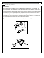
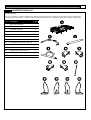
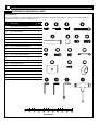
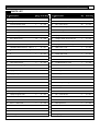
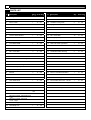
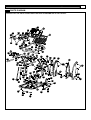
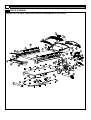
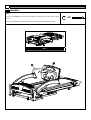
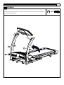
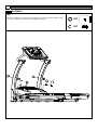
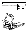
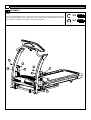
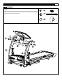
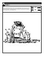
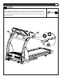
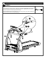
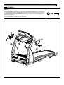
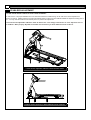
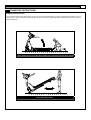
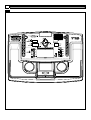
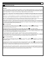
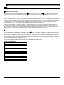
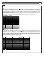
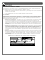
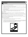
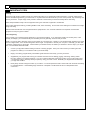
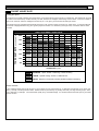
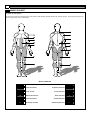
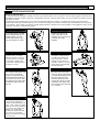
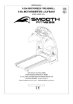
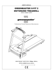
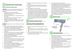
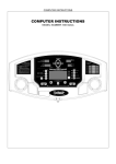
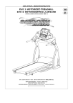
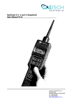
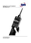
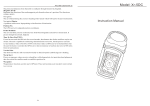
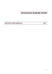
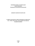
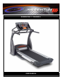
MOMENTUM T7 TREADMILL USER MANUAL 2 MOMENTUM T7 TREADMILL PRECAUTIONS For future service or related questions: Please staple your receipt and/or write in the name and phone number of the retail store where you purchased y our treadmill. Name: ______________________________ Phone Number: ___________________ Receipt: ______________________ Precautions: WARNING: To reduce the risk of burns, f ire, electric shock, or injury to persons, read the f ollowing important precautions and inf ormation bef ore operating the treadmill. It is the responsibility of the owner to ensure that all users of this treadmill are adequately informed of all warnings and precautions. • Use the treadmill only as described in this manual. • Place on a lev el surface, with 6 feet (2 m) of clearance behind it. Do not place the treadmill on any surf ace that blocks air openings. To protect the f loor or carpet f rom damage, place a mat under the treadmill. • When choosing a location for the treadmill be sure the location and position permit access to a plug. • Keep the treadmill indoors, away f rom moisture and dust. Do not put the treadmill in a garage or covered patio, or near water. • Do not operate the treadmill where aerosol products are used or where oxy gen is being administered. • Keep children under the age of 12 and pets away from the treadmill at all times. • The treadmill should not be used by persons weighing more than 400lbs. • Nev er allow more than one person on the treadmill at a time. • Wear appropriate exercise clothing when using the treadmill. Do not wear loose clothing that could become caught in the treadmill. Athletic support clothes are recommended f or both men and women. Alway s wear athletic shoes. Never use the treadmill with bare feet, wearing only stockings, or in sandals. • When connecting the power cord, plug the power cord into a grounded circuit. No other appliance should be on the same circuit. • Alway s straddle the belt and allow it to start moving before stepping onto the belt. • Alway s examine your treadmill bef ore using to ensure all parts are in working order. • Allow the belt to f ully stop bef ore dismounting. • Nev er insert any object or body parts into any opening. • Follow the saf ety inf ormation in regards to plugging in your treadmill. • Keep the power cord away f rom the incline wheels and do not run the power cord underneath your treadmill. Do not operate the treadmill with a damaged or f rayed power cord. • Alway s unplug the treadmill bef ore cleaning and/or servicing. Serv ice to your treadmill should only be performed by an authorized serv ice representativ e, unless authorized and/or instructed by the manufacturer. Failure to follow these instructions will v oid the treadmill warranty. • Nev er leave the treadmill unattended while it is running. www.greenmasterfitness.com.tw 3 POWER REQUIREMENTS Power Requirements: IMPROPER CONNECTION OF THE EQUIPMENT GROUNDING CONNECTOR CAN RESULT IN A RISK OF AN ELECTRIC SHOCK. CHECK WITH A QUALIFIED ELECTRICIAN OR SERVICE MAN IF Y OU ARE IN DOUBT AS TO WHETHER THE PRODUCT IS PROPERLY GROUNDED. DO NOT MODIFY THE PLUG PROVIDED WITH THE PRODUCT, IF IT WILL NOT FIT THE OUTLET; HAVE A PROPER OUTLET INSTALLED BY A QUALIFIED ELECTRICIAN. This treadmill can be seriously damaged by sudden voltage changes in y our home’s electrical power. Voltage spikes, surges and noise interference can result from weather conditions or f rom other appliances being turned on or off. To reduce the possibility of treadmill damage, alway s use a surge protector (not included) with y our treadmill. This treadmill must be grounded to reduce the risk of electrical shock. Grounding prov ides a path of least resistance f or electric current, should the treadmill malf unction. This treadmill comes with an electrical cord hav ing an equipment-grounding conductor and a grounding plug. Alway s plug the power cord into a surge protector, and plug the surge protector into an appropriate outlet that is properly installed and grounded in accordance with all local codes and ordinances. This product is f or use on a nominal 230-v olt circuit, and has a grounding plug that looks like the plug illustrated in the drawing below. 4 MOMENTUM T7 TREADMILL PREASSEMBLY Open the boxes: Y ou are now ready to open the boxes of y our new equipment. Make sure to inv entory all of the parts that are included in the boxes. Check the Contents Checklist and Hardware Comparison Chart f or a full count of the number of parts included for this product to be assembled properly. Gather your tools: Bef ore starting the assembly of your unit, make sure that y ou hav e gathered all the necessary tools you may require to assemble the unit properly. Having all of the necessary equipment at hand will sav e time and make the assembly quick and hassle-f ree. Clear your work area: Make sure that y ou hav e cleared away a large enough space to properly assemble the unit. Make sure the space is free from anything that may cause injury during assembly. After the unit is fully assembled, make sure there is a comfortable amount of free area around the unit f or unobstructed operation. Invite a friend: Some of the assembly steps may require heavy lifting. It is recommended that you obtain the assistance of another person when assembling this product. User Weight Limitation: Please note that there is a weight limitation for this product. If you weigh more than 400lbs. it is not recommended that you use this product. Serious injury may occur if the user’s weight exceeds the limit shown here. This product is not intended to support users whose weight exceeds this limit. www.greenmasterfitness.com.tw CONTENTS CHECKLIST Carton contents: For y our convenience, we have identif ied the contents of the shipping carton. Please check to make sure you have all of the components before assembly. This chart is prov ided to help you identify the components used in the assembly of this product. No. Description Qty. A Main Frame Assembly 1 B Front Handlebar Assembly 1 C Handlebar Assembly 2 3 Console Support Tube 1 10 Handlebar Rear End Cap - Left # 1 1 11 Handlebar Rear End Cap - Left # 2 1 12 Handlebar Rear End Cap - Right # 1 1 13 Handlebar Rear End Cap - Right # 2 1 27 Upright Support Tube 2 41 Upright Plastic Shroud Left #1 1 42 Upright Plastic Shroud Left #2 1 43 Upright Plastic Shroud Right #2 1 44 Upright Plastic Shroud Right #1 1 5 6 MOMENTUM T7 TREADMILL HARDWARE COMPARISON CHART Hardware chart: For y our convenience, we have identif ied the hardware used in the assembly of this product. This chart is prov ided to help you identify those items that may be unf amiliar to you. No. Description Qty. 4 M6 x 20mm Allen Head Bolt 2 8 #8 x 19mm Screw 20 9 #8 x 25mm Screw 8 18 M8 x 95mm Screw 2 21 1/2" x 68mm Bolt 2 22 Plastic Spacer 4 23 M8 x 25mm Allen Head Bolt 2 24 M10 x 20mm Allen Head Bolt 4 25 M8 x 20mm Allen Head Bolt 2 28 M8 x 15mm Allen Head Bolt 6 40 M8 x 10mm Allen Head Bolt 4 104 Console Screw 2 106 Upright Cov er 2 107 M6 x 15mm Screw 2 109 Metal Cap 2 A 4mm Wrench 1 B 5mm Wrench 1 C Phillips Head Wrench 1 D 6mm Wrench 1 MILLIMETERS www.greenmasterfitness.com.tw 7 PARTS LIST No. Description Qty. Order No. No. Description Qty. Order No. 1 Computer 1 T7 - 001 35 Cushion 4 T7 - 035 2 Key pad 1 T7 - 002 36 M6 x 13mm Washer 2 T7 - 036 3 Console Support Tube 1 T7 - 003 37 #8 x 15mm Screw 38 T7 - 037 4 M6 x 20mm Allen Head Bolt 2 T7 - 004 38 Console Housing - Bottom 1 T7 - 038 5 Console Support Tube 1 T7 - 005 39 Deck Fixing Tube 1 T7 - 039 6 N/A 40 M8 x 10mm Allen Head Bolt 4 T7 - 040 7 Plastic Fixing Insert 8 T7 - 007 41 Upright Plastic Shroud Left #1 1 T7 - 041 8 #8 x 19mm Screw 24 T7 - 008 42 Upright Plastic Shroud Left #2 1 T7 - 042 9 #8 x 25mm Screw 8 T7 - 009 43 Upright Plastic Shroud Right #2 1 T7 - 043 10 Handlebar Rear End Cap - Left # 1 1 T7 - 010 44 Upright Plastic Shroud Right #1 1 T7 - 044 11 Handlebar Rear End Cap - Left # 2 1 T7 - 011 45 Side Cov er - Left 1 T7 - 045 1 T7 - 012 46 Side Cov er - Right 1 T7 - 046 1 T7 - 013 47 Power Switch Set 1 T7 - 047 12 13 Handlebar Rear End Cap - Right # 1 Handlebar Rear End Cap - Right # 2 14 Handlebar Grip 2 T7 - 014 48 M5 x 10mm Screw 2 T7 - 048 15 Handlebar 2 T7 - 015 49 Motor Hood 1 T7 - 049 16 Hand Pulse Sensor 2 T7 - 016 50 Top Maintenance Cover 1 T7 - 050 17 Console Housing - Upper 1 T7 - 017 51 #8 x 50mm Screw 2 T7 - 051 18 M8 x 95mm Screw 2 T7 - 018 52 Aluminum Side Rail 2 T7 - 052 19 Upright - Left 1 T7 - 019 53 Running Belt 1 T7 - 053 20 Upright - Right 1 T7 - 020 54 Running Deck Rear Cover 1 T7 - 054 21 1/2" x 68mm Bolt 2 T7 - 021 55 Rear Foot Platf orm 1 T7 - 055 22 Plastic Spacer 4 T7 - 022 56 Rubber Spacer - Left 1 T7 - 056 23 M8 x 25mm Allen Head Bolt 2 T7 - 023 57 Rubber Spacer - Right 1 T7 - 057 24 M10 x 20mm Allen Head Bolt 4 T7 - 024 58 Running Deck 1 T7 - 058 25 M8 x 20mm Allen Head Bolt 2 T7 - 025 59 Deck Rubber Cushion 10 T7 - 059 26 Adjustable Cy linder 2 T7 - 026 60 M10 x 35mm Bolt 1 T7 - 060 27 Upright Support Tube 2 T7 - 027 61 M5 x 15mm Screw 2 T7 - 061 28 M8 x 15mm Allen Head Bolt 16 T7 - 028 62 Clip 2 T7 - 062 29 M6 x 55mm Allen Head Bolt 2 T7 - 029 63 Elev ation Motor 1 T7 - 063 30 M14 x 113mm Bolt 2 T7 - 030 64 M10 Ny lon Nut 2 T7 - 064 31 Bushing 4 T7 - 031 65 Tension Wheel 1 T7 - 065 32 Stabilizer 2 T7 - 032 66 Front Vent Cov er 1 T7 - 066 33 Base Frame 1 T7 - 033 67 Rear Vent Cover 1 T7 - 067 34 Running Deck Fixed Tube Sleeve 2 T7 - 034 68 Logo Light Bracket 1 T7 - 068 8 MOMENTUM T7 TREADMILL PARTS LIST No. Description Qty. Order No. No. Description Qty. Order No. 69 Driv ing Motor 1 T7 - 069 103 #8 x 35mm Screw 4 T7 - 103 70 Roller Carbon Brush 1 T7 - 070 104 Console Screw 2 T7 - 104 71 Motor Holder 1 T7 - 071 105 Handlebar Fixing Plate 2 T7 - 105 72 Motor Holder Adjustment 1 T7 - 072 106 Upright Cov er 2 T7 - 106 73 M10 x 136mm Bolt 1 T7 - 073 107 M6 x 15mm Screw 2 T7 - 107 74 M10 x 63mm Bolt 1 T7 - 074 108 Front Handle bar 1 T7 - 108 75 Motor Driv e Belt 1 T7 - 075 109 Metal Cap 3 T7 - 109 76 Tension Wheel Bracket 1 T7 - 076 110 M8 x 45mm Bolt 12 T7 - 110 77 Transf er Board 1 T7 - 077 111 Emergency Stop 1 T7 - 111 78 Front Roller 1 T7 - 078 112 Hand Pulse Sensor Wire - Upper 2 T7 - 112 79 Front Roller Shaft 1 T7 - 079 113 Side Rail Guide Light Board 1 T7 - 113 80 Deck Frame 1 T7 - 080 114 N/A 81 Micro Switch 1 T7 - 081 115 N/A 82 M8 x 70mm Bolt 3 T7 - 082 116 Handle Bar Plastic Bushing 2 T7 - 116 83 8 x 16 x T2.0 Washer 13 T7 - 083 117 Motor Control Board 1 T7 - 117 84 Motor Hood Side Cover - Left 1 T7 - 084 118 Motor Control Board Fan 1 T7 - 118 85 Motor Hood Side Cover - Right 1 T7 - 085 119 Main Transf ormer 1 T7 - 119 86 Frame Side Cover - Left 1 T7 - 086 120 N/A 87 Frame Side Cover - Right 1 T7 - 087 121 N/A 88 Plastic Clamp - Top 2 T7 - 088 122 N/A 89 Plastic Clamp - Bottom 2 T7 - 089 123 Motor Control Board Cov er 1 T7 - 123 90 Bracket 2 T7 - 090 124 Motor Control Board Radiator 1 T7 - 124 91 M8 x 25mm Screw 4 T7 - 091 125 Rear Frame 1 T7 - 125 92 Rear Roller 1 T7 - 092 126 Foot Platf orm Support Frame 1 T7 - 126 93 Rear Roller Shaft 1 T7 - 093 127 Deck Frame Side Cover - Left #2 1 T7 - 127 94 M8 x 43mm Bolt 2 T7 - 094 128 Deck Frame Side Cover - Right #2 1 T7 - 128 95 M8 Ny lon Nut 12 T7 - 095 129 10 x 16 Washer 1 T7 - 129 96 Deck Wheel 2 T7 - 096 130 Side Rail Guide Light 2 T7 - 130 97 Rubber Dot 1 SET T7 - 097 98 Deck Wheel Bracket 2 T7 - 098 1 T7 - 099 1 T7 - 100 99 100 Elev ation Support Tube Side Cover - Lef t Elev ation Support Tube Side Cov er - Right 101 Elev ation Support Tube 1 T7 - 101 102 Motor Belly Pan 1 T7 - 102 www.greenmasterfitness.com.tw 9 PARTS DIAGRAM A MAJORITY OF THE PARTS SHOWN HERE HAVE BEEN PREASSEMBLED AT THE FACTORY. 1 17 2 16 16 40 111 38 114 112 115 113 40 110 108 16 105 112 116 16 5 4 110 104 3 105 116 10 112 8 15 7 11 12 15 8 13 7 8 18 14 109 21 25 19 43 109 24 23 25 24 26 44 18 8 8 9 20 21 27 22 106 24 45 47 28 107 42 14 22 24 41 8 29 46 107 48 30 106 26 9 8 28 8 27 29 31 28 28 35 32 31 37 35 33 34 30 34 35 32 37 37 37 10 MOMENTUM T7 TREADMILL PARTS DIAGRAM A MAJORITY OF THE PARTS SHOWN HERE HAVE BEEN PREASSEMBLED AT THE FACTORY. www.greenmasterfitness.com.tw PARTS DIAGRAM A MAJORITY OF THE PARTS SHOWN HERE HAVE BEEN PREASSEMBLED AT THE FACTORY. 11 12 MOMENTUM T7 TREADMILL ASSEMBLY STEP 1: Remov e y our treadmill from the carton and place it on the f loor in an open area as shown in FIG. 1. Secure the Computer (1) to the Console Tube (5) using two Console Screws (104). FIG. 1 x2 www.greenmasterfitness.com.tw ASSEMBLY STEP 2: Rotate the Left and Right Uprights (19 and 20) up into position and secure them with f our M8 x 15mm Allen Head Bolts (28). x4 13 14 MOMENTUM T7 TREADMILL ASSEMBLY STEP 3: Attach one Upright Cover (106) to the Left Upright (19) and secure with one M6 x 15mm Screw (107). Repeat this procedure on the Right Upright (20). x2 x2 www.greenmasterfitness.com.tw ASSEMBLY STEP 4: Attach the Suspension System Hardware Assembly (26) to the Left Upright (19) and secure with two Plastic Spacers (22), one ½” x 68mm Bolt (21) and one M8 x 25mm Bolt (23). Repeat this procedure on the Right Upright (20). x2 x4 x2 15 16 MOMENTUM T7 TREADMILL ASSEMBLY STEP 5: Attach one Upright Support Tube - Bottom (27) to the Left Upright (19) and secure using two M10 x 20mm Allen Head Bolts (24) at the top bracket and one M8 x 15mm Allen Head Bolt (28) at the bottom bracket. Repeat this procedure on the Right Upright (20). x4 x2 www.greenmasterfitness.com.tw ASSEMBLY STEP 6: Attach the Console Support Tube (3) to the Console (1), Left Upright (19) and Right Upright (20). Secure using two M6 x 20mm Allen Head Bolts (4), two Metal Caps (109) and two M8 x 95mm Screws (18). x2 x2 x2 17 18 MOMENTUM T7 TREADMILL ASSEMBLY STEP 7: Attach the Upright Plastic Shroud Left #1 (41) and Upright Plastic Shroud Left #2 (42) to the Left Upright (19) and secure with six #8 x 19mm Screws (8) and four #8 x 25mm Screws (9). Repeat the procedure on the Right Upright (20) to attach the Upright Plastic Shroud Right #2 (43) and Upright Plastic Shroud Right #1 (44). x12 x8 www.greenmasterfitness.com.tw ASSEMBLY STEP 8: Connect both the Hand Pulse Sensor Wires - Upper (112) to the Hand Pulse Sensor Wires (16) as shown. NOTE: Make sure all wires are recessed into the tube, do not trap or pinch any of the wires. Attach the Front Handlebar (108) to the Console Support Tube (5) and secure using f our M8 x 10mm Allen Head Bolts (40). x4 19 20 MOMENTUM T7 TREADMILL ASSEMBLY STEP 9: Connect the Motion Control Sensor Wire - Upper (114) coming from the Left Upright (19) to the Motion Console Sensor Wire (6) coming from the Handlebar (15) as shown. NOTE: Make sure all wires are recessed into the tube, do not trap or pinch any of the wires. Attach one Handlebar (15) to the Left Upright (19). Secure using one M8 x 20mm Allen Head Bolt (25). Repeat this entire procedure on the Right Upright (20). 15 19 20 15 20 25 19 25 x2 www.greenmasterfitness.com.tw ASSEMBLY STEP 10: Attach the Handlebar Rear End Cap – Left #1 (10) and Handlebar Rear End Cap – Left #2 (11) to the Left Upright (19). Secure using four #8 x 19mm Screws (8). Repeat the procedure on the Right Upright (20) to attach the Handlebar Rear End Cap – Right #1 (12) and Handlebar Rear End Cap – Right #2 (13). Now y our Momentum T7 treadmill is fully assembled. 13 8 8 20 12 8 11 19 10 x8 21 22 MOMENTUM T7 TREADMILL STABILIZER ADJ USTMENT FOLLOW THESE INSTRUCTIONS TO LEVEL YOUR TREADMILL: An unev en floor or improper stabilizer lev el can cause the treadmill to wobble during use as well as the incline adjustment to f unction incorrectly. Please follow the procedure described below to make sure the treadmill stabilizer is adjusted correctly prior to use. Y ou may need the assistance of another person to perform this adjustment. First locate the two adjustable stabilizers under the base frame. Then simply rotate them in or out to adjust the level of the treadmill. When properly adjusted the treadmill should sit firmly on both stabilizers and all cushions. Locate the two adjustable stabilizers under the base frame. Treadmill should sit firmly on both stabilizers and all cushions. www.greenmasterfitness.com.tw TRANSPORT INSTRUCTIONS TRANSPORT INSTRUCTIONS: To mov e the treadmill, simply lift the deck from the rear so that the treadmill rests on the f ront transportation wheels. Roll to a desired location. After moving the treadmill alway s be sure to follow the STABILIZER ADJUSTMENT instructions to lev el the treadmill before use. Lift the deck from the rear so that the treadmill rests on the front transportation wheels. Roll to a desired location. 23 24 MOMENTUM T7 TREADMILL www.greenmasterfitness.com.tw 25 COMPUTER OPERATION A B F G C H D E I J E K Calories/Calories Per Hour A B Time/Distance Express Incline Buttons C F Heart Rate Preset Programs E H Express Speed Buttons Incline/Level G J Speed and Incline Profile Display Recov ery I Emergency Stop Button K POWER ON: Set the POWER SWITCH, located on the bottom of the left handle bar upright tube, to ON and insert the SAFETY KEY. All the LED lights will auto scan then display the factory def ault setting: CALORIES window will display : 0 TIME window will display : 0:00 SPEED window will display : SPEED INCLINE window will display : 0 HEART RATE window will display : 0 SLEEP / DISPLAY MODE: When the power is ON the computer will automatically enter SLEEP MODE if it is left idle f or 3 minutes without receiv ing any input. Press any button to return to POWER ON status when the computer is in the SLEEP MODE. To cancel the SLEEP MODE feature using the DISPLAY MODE and always keep the console display on, press the EMERGENCY STOP button to power off the treadmill, press and hold the SPEED UP and DOWN buttons, press the EMERGENCY STOP button again to power on the treadmill. After one short beep sound the HEART RATE window will show “1”. Press the START button then TIME LED window will show “ON” (SLEEP MODE f eature on) or “OFF” (SLEEP MODE f eature off). Press the INCLINE UP and DOWN buttons to switch between “ON” and “OFF” then press STOP to sav e the setting and return to POWER ON mode. 26 MOMENTUM T7 TREADMILL COMPUTER OPERATION OPERATING INSTRUCTIONS: 3 SECONDS ALERT: To ensure y ou are well prepared before the belt starts mov ing, every time y ou press the START button to start the belt, the SPEED window will countdown 3 seconds with the LED showing “3-2-1” then the belt will start mov ing. PAUSE/STOP: When the treadmill is running, press the STOP button to pause the treadmill. All figures on the display ed on the LED will freeze. Press START to resume the program and all displays will continue the performance until the program f inishes. If y ou continue pressing the STOP twice, then all data will return to 0 and the treadmill will return to POWER ON status. If there is no action within 30 seconds, the treadmill will return to POWER ON status. ENGLISH/METRIC CONVERSION: The treadmill computer display can show ENGLISH and METRIC information. The factory should hav e the proper setting on this f or different markets. In case that the treadmill needs to be conv erted between METRIC and ENGLISH readout, please f ollow the procedure as below: 1. Press the EMERGENCY STOP button to power off the treadmill. Press the START button on the computer and hold it. Press the EMERGENCY STOP button again to power on the treadmill then release the START button. The computer will sound one short beep and METRIC or ENGLISH LED light up. 2. Press the START button to switch between METRIC and ENGLISH then press the STOP button to conf irm the selection and return to the POWER ON status. QUICK START: When the treadmill is in POWER ON status, press the START button to activate the QUICK START program. The speed will start from 0.5MPH/0.8KMPH. Press the SPEED UP/DOWN button to change the speed. Press the INCLINE UP/DOWN button to elev ate the treadmill. The TIME, CALORIES and DISTANCE will count up f rom 0. PAUSE / STOP During the workout press the STOP button once to pause the treadmill. Press the STOP button twice to delete all workout data and return to POWER ON status. RECOVERY Recov ery is the feature to let the user test their physical condition after a workout. The recovery rating is determined by measuring how quickly the user’s pulse slows down af ter the workout to justify the user physical condition. The f aster the pulse slows down, the better the user’s physical condition. User’s can record their recov ery rating after each workout to use f or ref erence. To operate the RECOVERY, press the RECOVERY button after completing a workout. The treadmill will enter the PAUSE/STOP status. Put both hands on the hand pulse sensors within 10 seconds (for models equipped with a chest belt pulse transmitter, keep the chest belt on, no need to hold the hand pulse). The pulse receiver will scan and detect the user’s pulse in 10 seconds and enter the RECOVERY procedure. TIME counts down f rom 01:00 to 00:00. The SPEED LED window will show the RECOVER RATING after the one-minute count down. The lower the number the better the fitness lev el. Record the rating for future comparison. During the RECOVERY procedure, if you want to stop the RECOVERY and stop workout, press the STOP/ENTER button and return to POWER ON status. During the RECOVERY procedure, if you want to continue the previous program, press the START button to continue the prev ious program. After pressing the RECOVERY button, if the pulse receiv er fails to scan and receive the user’s pulse the computer will stay at PAUSE/STOP status. Press the STOP/ENTER button to return to POWER ON status or press the START button to continue the prev ious program. www.greenmasterfitness.com.tw 27 COMPUTER OPERATION PROGRAM: To select other programs, y ou will need to select the USER first. Press the SPEED UP/DOWN button to select the USER CODE from U1 to U9 then press the ENTER button to conf irm the user code. If the user information has been prev iously input, press the ENTER button again and hold it for 5 seconds then the computer will skip the user information set up procedure and enter the program select procedure. To input the new user inf ormation, please follow the procedure as below: WEIGHT set up – After the User Code conf irmation procedure, The CALORIES/CAL PER HOUR display will show the def ault or prev ious setting and begin blinking. Press the SPEED UP/DOWN button to adjust the user weight information then press ENTER to conf irm. HEIGHT set up – After the WEIGHT set up procedure, the TIME/DISTANCE display will show the default or prev ious setting and begin blinking. Press the SPEED UP/DOWN button to adjust the user height inf ormation then press ENTER to conf irm. AGE set up – After the HEIGHT set up procedure, the INCLINE/LEVEL display will show the default or previous setting and begin blinking. Press the SPEED UP/DOWN button to adjust the user age inf ormation then press ENTER to conf irm. TARGET HEART RATE set up – After the AGE set up procedure, the TARGET HEART RATE displays in the PULSE LED window and is blinking. The f actory TARGET HEART RATE setting is based on 85% of the maximum user heart rate. The maximum user heart rate is calculated using the f ormula: 220 minus the user age. As an example, for age 35 the maximum user heart rate should be 185 and 85% of the maximum user heart rate will be 157. GOAL COURSE TIME: When the computer is in POWER ON status press the button on the console. The LED on button will light up. If no buttons are pressed after this within 3 minutes the program will return to POWER ON status. If you wish to return to POWER ON status, press the STOP button any time. The TIME LED will light up, show the preset time as 30:00 and blink. After press the button. Press the SPEED UP/DOWN buttons to set your ideal workout time then press the ENTER button to conf irm. Then press the START button to start. After pressing the START button the TIME counts down f rom the preset time. The other information counts up until the treadmill stops. The Speed starts f rom 2MPH/3.2KMPH and the incline starts f rom lev el 0. Press the SPEED UP/DOWN buttons to adjust the speed. Press the INCLINE UP/DOWN buttons to adjust the incline lev el. During exercise press STOP to pause the program. Speed and Incline Lev el return to the beginning levels while the other inf ormation (Time, Distance, Calories) is paused. To recall v alues and resume exercising press START. Pressing the STOP button again within 30 seconds returns all data to zero and the computer returns to POWER ON status. If no buttons are pressed within 30 seconds the computer automatically returns to POWER ON status and all data returns to zero. GOAL COURSE DISTANCE: When the computer is in POWER ON status press the button on the console. The LED on button lights up. If no buttons are pressed within 3 minutes the program will return to POWER ON status. If y ou wish to return to POWER ON status, press the STOP button any time. The DISTANCE LED will light up, show the preset distance as 0 and begin blinking. After press the button. Press the SPEED UP/DOWN buttons to set up the ideal distance then press the ENTER button to confirm. Then press the START button to start. After pressing the START button the DISTANCE counts down f rom the preset distance. The other inf ormation counts up until the treadmill stops. The Speed starts from 2MPH/3.2KMPH and incline starts from lev el 0. During exercise press STOP to pause the program. Speed and Incline Level return to the beginning lev els while the other inf ormation (Time, Distance, Calories) is paused. To recall values and resume exercising press START. Pressing the STOP button again within 30 seconds returns all data to zero and the computer returns to POWER ON status. If no buttons are pressed within 30 seconds the computer automatically returns to POWER ON status and all data returns to zero. 28 MOMENTUM T7 TREADMILL GOAL COURSE CALORIES: When the computer is in POWER ON status press the button on the console. The LED button lights up. If no buttons are pressed within 3 minutes the program will return to POWER ON status. If y ou wish to return to POWER ON status, press the STOP button any time. The CALORIES LED will light up and show the preset calories burned as 0 and blinking. After press the button. Press the SPEED UP/DOWN buttons to set up the desired calories then press the ENTER button to conf irm. Then press the START button to start. After pressing the START button the CALORIES count down f rom the preset calories. The other information counts up until the treadmill stops. The Speed starts from 2MPH/3.2KMPH and the incline starts from lev el 0. Press the SPEED UP/DOWN buttons to adjust the speed. Press the INCLINE UP/DOWN buttons to adjust the incline level. During exercise press STOP to pause the program. The Speed and Incline Lev el return to the beginning levels while the other inf ormation (Time, Distance, Calories) is paused. To recall values and resume exercising press START. Pressing the STOP button again within 30 seconds returns all data to zero and the computer returns to POWER ON status. If no buttons are pressed within 30 seconds the computer automatically returns to POWER ON status and all data returns to zero. KILLER HILLS: When the treadmill is in PROGRAM SELECT status, press the button. The LEVEL display will show 01 and be blinking. There are total of 12 different workout levels that can be selected. Press the SPEED UP/DOWN button to select the lev el then press the ENTER button. The TIME LED will show a pre-set workout time of 24 minutes. Press the SPEED UP/DOWN button to adjust the time, 4 minutes per segment f or ev ery adjustment. Press the ENTER button to confirm the workout time then press the START button to start the program. The program will start with 2 minutes in MIN. GRADE% and 2 minutes in MAX. GRADE%. Repeat in 4 minute segments until the time counts down to zero. Pre-set speed 2.0MPH/3.2KMPH, adjust the speed using the SPEED UP/DOWN BUTTON, KILLER HILLS WORKOUT LEVEL MIN. GRADE% MA X. GRADE% 1 2 3 4 0 1 2 3 4 5 6 7 5 6 7 8 4 5 6 7 8 9 10 11 9 10 11 12 8 9 10 11 12 13 14 15 www.greenmasterfitness.com.tw 29 COMPUTER OPERATION SPEED INTERVAL: When treadmill is in PROGRAM SELECT status, press button. The LEVEL display will show a blinking 01. There are a total of 12 diff erent workout levels that can be selected. Press the SPEED UP/DOWN button to select the lev el then press the ENTER button. The TIME LED will show a pre-set workout time of 24 minutes. Press the SPEED UP/DOWN button to adjust the time, 4 minutes per segment for every adjustment. Press the ENTER button to conf irm the workout time then press the START button to start the program. The program will start with 2 minutes in MIN. SPEED and 2 minutes in MAX. SPEED. Repeat this in 4 minutes segments until the time counts down to zero. Pre-set INCLINE LEVEL at 0%. Adjust the incline lev el using the INCLINE UP/DOWN button during the workout. SPEED INTERVAL WORKOUT LEVEL MIN. SPEED (MPH) MA X. SPEED (MPH) 1 1.8 3.0 2 2.0 3.4 3 4 5 6 2.2 2.4 2.6 2.8 3.8 4.2 4.6 5.0 7 8 9 10 3.0 3.2 3.4 3.6 5.4 5.8 6.2 6.6 11 12 3.8 4.0 7.0 7.2 WEIGHT LOSS: When the treadmill is in PROGRAM SELECT status, press the button. The LEVEL will display a blinking 01. There are a total of 12 diff erent workout levels that can be selected. Press the SPEED UP/DOWN button to select the lev el then press the ENTER button. The TIME LED will show a pre-set workout time of 30 minutes. Press the SPEED UP/DOWN button to adjust the time, 5 minutes per segment for every adjustment. Press the ENTER button to conf irm the workout time then press the START button to start the program. The program will start with 2 .5minutes in MIN. SPEED/GRADE% and 2.5 minutes in MAX. SPEED/GRADE%. Repeat in 5 minute segments until the time counts down to zero. WEIGHT LOSS WORKOUT 1 1.6 2.8 MINI. GRADE% 0 2 3 4 5 1.8 2.0 2.2 2.4 3.0 3.2 3.4 3.6 0 1 1 2 4 5 6 7 6 7 8 9 2.6 2.8 3.0 3.2 3.8 4.0 4.2 4.4 2 3 3 3 8 9 10 11 10 11 12 3.4 3.6 3.8 4.6 4.8 5.0 4 4 4 12 13 14 LEVEL MIN. SPEED (MPH) MA X. SPEED (MPH) MA X GRADE% 3 30 MOMENTUM T7 TREADMILL COMPUTER OPERATION CUSTOM SAVE: The program can allow one custom programs to be set by users and store the settings for repeated workouts. The maximum workout time of each user program is 60 minutes. During the workout after the TIME counts up to 60:00, the treadmill will start a one-minute cool down procedure automatically. To set and store the user programs, please f ollow the procedure below: SET AND SAVE THE USER PROGRAM When the treadmill is in PROGRAM SELECT status, press the button. The screen will display C1. Press button again to Select between C1 to C3 and press the STOP/ENTER button to enter the user program then press the START button. Speed starts at 3.2 km/h / 2.0 mph and the incline lev el starts at level 0. Each section of SPEED/INCLINE is one minute. Press the SPEED UP/DOWN buttons to change the speed and press the INCLINE UP/DOWN buttons to change the incline during the workout. The computer will take the actual speed and incline level at the last second of each minute section and temporary sav e as the speed and incline level of that minute section. Continue the workout until y ou want to stop. Press the STOP button to enter the one-minute cool down session. The computer will automatically enter the sav e program status after the one-minute cool down session. If you want to skip the cool down procedure, press the STOP button to enter the save program status. When the computer is in sav e program status, the “CUSTOM SAVE” button will blink slowly . Press the ENTER button to sav e this program or press the STOP button to delete the program and return to POWER ON status. EDIT PREVIOUS SAVED PROGRAM Edit the Speed and Incline without extending the prev iously saved workout time: Simply press the SPEED UP/DOWN and INCLINE UP/DOWN buttons to change the speed and incline lev el during the workout then f ollow the SET AND SAVE procedure after completing the workout. Extend the workout time f rom the previously sav ed program: If you want to extend the total workout time from the prev iously saved program press the START button anytime during the workout. The LED of the CUSTOM SAVE button will light up and blink for 10 seconds then stay lit up. After completing the prev iously saved program the treadmill will start a one-minute cool down session. Press the START button again during the cool down session and the treadmill will skip the cool down procedure and continue running at a speed of 3.2 km/h / 2.0 mph and incline of lev el 0. Press the SPEED UP/DOWN and INCLINE UP/DOWN buttons for every minute section then follow the SET AND SAVE procedure after completing the workout. If you already press the START button once during the workout and intend to extend the workout time but decide not to extend the workout time, press the START button again to switch off the LED light of CUSTOM SAVE button. Or wait till the previous saved program complete and complete the cool down procedure then follow the SET AND SAVE procedure. HEART RATE CONTROL: When the treadmill is in PROGRAM SELECT status, press the button. TIME SET UP – After selecting the HEART RATE CONTROL program, the TIME LED will show a blinking pre-set workout time of 60:00. Press the SPEED UP/DOWN button to adjust the workout time then press the ENTER button to confirm. Press the START button to start the program. During the program please make sure to wear the chest belt or hold the hand pulse contact sensor on the handle bar at all times. Exercising without chest belt or f ailure to hold the contact sensor will cause the program f ail and discontinue. www.greenmasterfitness.com.tw 31 COMPUTER OPERATION WARM UP – After completing the TIME set up and starting the program, there is a 3 minute WARM UP program to help you reach the minimum target workout heart rate. The speed will start from 2MILE/3.2KM and the incline level will start from 0. If the heart rate monitor senses the user’s pulse properly but the actual user’s pulse does not reach 65% of the max. heart rate (( 220-age) x 65%) then the speed will increase by 0.5 mph /0.8 km/h every 30 seconds. If the actual pulse reaches 65% of the max. heart rate the speed will remain unchanged. If the actual pulse remains at 65% of the max. heart rate f or more than one minute the speed will be maintained until the warm up program is f inished and then go to the HEART RATE CONTROL main program. If y ou cannot nd reach the minimum target workout heart rate in 3 minutes, the program will continue the 2 3 minute WARM UP program. During nd the 2 WARM UP program, the speed will remain the same speed as in the first WARM UP program. If the heart rate monitor senses the user’s pulse properly but the actual user’s pulse does not reach 65% of the max. heart rate (( 220-age) x 65%) , the incline lev el will add 1% ev ery 30 seconds. When the actual pulse rate reaches 65% of the max. heart rate (( 220-age) x 65%) , the incline will stop changing and continue the same speed and same incline lev el until the time counts down to zero then enters the nd HEART RATE CONTROL main program. If during the 2 WARM UP the user still can not reach the 65% of the max. heart rate , rd the computer will continue on to the 3 WARM UP procedure for 3 minutes and both speed and incline level will be remain the nd rd same as the 2 WARM UP until the time counts down to zero. If the 3 WARM UP program still cannot bring up the actual pulse rate to the minimum target workout heart rate, the program will stop and SPEED LED will show FAIL. HEART RATE CONTROL MAIN PROGRAM – After the actual pulse rate reaches the minimum target workout heart rate and completes the warm up program, the computer will go into the main program and the time will count down f rom the pre-set time. During the main program, if the actual pulse rate cannot reach the maximum target workout heart rate, the incline lev el will be increased by 1% ev ery 15 seconds until the pulse rate reaches the maximum target workout heart rate or the incline lev el will increase by 15%. After the incline level increases to 15% but still does not reach the maximum target workout heart rate the speed will be increase by 0.5MILE/0.8KM every 15 seconds until the pulse rate reaches the maximum target workout heart rate. If the actual pulse is higher than the maximum target workout heart rate, then the incline will be reduced 1% every 15 seconds until the actual heart rate meets the maximum target workout heart rate or the incline lev el will lower to 0%. Then the speed will be reduced by 0.5MILE/0.8KM every 15 seconds until the actual pulse meets the maximum target workout heart rate. COOL DOWN – After completing the HEART RATE CONTROL program and the time counts down to zero start the one-minute cool down program. The incline will return to 0% and the speed will lower to 2MILE/3.2KM as the time counts down from 1:00. USING THE CHEST BELT HEART RATE MONITOR: For proper operation, the chest belt should be worn with the monitor strapped across the f ront of your body just abov e the chest line as shown in the drawing on the right. The monitor needs a little body heat and moisture in order to work properly. To ensure correct operation y ou may want to wet the two rubber pickups under the belt prior to exercising. 32 MOMENTUM T7 TREADMILL MAINTAINENCE HOW TO MAINTAIN THE MOMENTUM T7 TREADMILL: Proper maintenance is very important to ensure y our treadmill is always in top working condition. Improper maintenance could cause damage or shorten the life of your treadmill and exceed any WARRANTY coverage. • Important: Nev er use abrasives or solv ents to clean the treadmill. To prevent damage to the computer, keep liquids away and keep it out of direct sunlight. • Inspect and tighten all parts of the treadmill regularly. Replace any worn parts immediately. BELT ADJUSTMENT: Belt adjustment and tension performs two f unctions: adjustment for tension and centering. The running belt has been adjusted properly at the f actory. Howev er transportation, unev en f looring or other unpredicted reasons could cause the belt to shift off center resulting in the belt rubbing with the plastic side rail or end caps and possibly causing damage. To adjust the belt back to it’s proper position please f ollow the directions below: • Walking belt has shifted to the left: First unplug the power cord f rom the surge protector. Using the hex key provided, turn the left rear roller adjustment bolt 1/4 turn in the clockwise direction. Plug the power cord back into the surge protector and run the treadmill at 2.5 mph. Y ou should see the belt start to correct itself, mov ing back towards the center. Repeat the above procedure until the walking belt is centered. It may be necessary to set walking belt tension once y ou hav e completed this procedure if the belt feels like it is slipping while walking. Refer below to the "Walking belt slipping" instructions. • Walking belt has shifted to the right: First unplug the power cord f rom the surge protector. Using the hex key provided, turn the right rear roller adjustment bolt 1/4 turn in the clockwise direction. Plug the power cord back into the surge protector and run the treadmill at 2.5 mph. Y ou should see the belt start to correct itself, mov ing back towards the center. Repeat the above procedure until the walking belt is centered. It may be necessary to set walking belt tension once y ou hav e completed this procedure if the belt feels like it is slipping while walking. Refer below to the "Walking belt slipping" instructions. • Walking belt is slipping: First unplug the power cord f rom the surge protector. Using the hex key provided, turn both the left and right rear roller adjustment bolts the same distance, usually a 1/4 turn in the clockwise direction. Plug the power cord back into the surge protector and run the treadmill at 2.5 mph. Y ou should now walk on the belt to determine if the belt is still slipping. Repeat the above procedure until the walking belt is not slipping. The tension should be just tight enough not to slip. WARNING! Do not over tighten rollers! This will cause premature roller bearing failure! Right and left tension bolts are located at the rear of the treadmill. www.greenmasterfitness.com.tw 33 MAINTAINENCE CLEANING: Routine cleaning of your treadmill will extend the product's lif e. • Warning: To prev ent electrical shock, be sure the power to the treadmill is OFF and the power cord is unplugged from the wall electrical outlet before attempting any cleaning or maintenance. • Important: Nev er use abrasives or solv ents to clean the treadmill. To prevent damage to the computer, keep liquids away and keep it out of direct sunlight. • After each workout: Wipe off the console and other treadmill surfaces with a clean, water dampened soft cloth to remov e excess perspiration. • Weekly: Use of a treadmill mat is recommended for ease of cleaning. Dirt f rom your shoes contacts the belt and ev entually makes it to underneath the treadmill. Vacuum underneath treadmill once a week. DECK LUBRICATION: The walking belt has been pre-lubricated at the factory. Howev er, it is recommended that the walking board be checked periodically for lubrication to ensure optimal treadmill perf ormance. Y our treadmill should not hav e to be lubricated usually within the f irst y ear or 400 hours of use. Ev ery 2 months of operation lift the sides of the walking belt and f eel the top surface of the walking board as f ar as y ou can reach. If you feel signs of silicone, no further lubrication is required. If it feels dry to the touch, f ollow the instructions below. Please use Lube 'N Walk (can be purchased from y our dealer or call the number on the front of the manual), or a non-petroleum based silicone such as "Napa 8300" (available at most stores). To apply lubricant to the walking belt: 1. Position the walking belt so that the seam is located on top and in center of the walking board. 2. Insert the spray nozzle into the spray head of the lubricant can. 3. While lifting the side of the walking belt, position the spray nozzle between the walking belt and the board approximately 6" from the front of the treadmill. Apply the silicone spray to the walking board, moving from the f ront of the treadmill to the rear. Repeat this on the other side of the belt. Spray approximately 4 seconds on each side. 4. Allow the silicone to "set" f or 1 minute bef ore using the treadmill. Spray lubricant from front to back. 34 MOMENTUM T7 TREADMILL IMPORTANT STEPS Warning: Bef ore using this product, please consult your personal physician for a complete physical examination. Frequent and strenuous exercise should be approved by your doctor f irst. If any discomf ort should result f rom your use of this product, stop exercising and consult y our doctor. Proper usage of this product is essential. Please read your manual caref ully before exercising. Please keep all children away f rom the equipment during use and when equipment is unattended. Alway s wear appropriate clothing, including athletic shoes, when exercising. Do not wear loose clothing that could become caught during exercising. Make sure that all bolts and nuts are tightened when equipment is in use. Periodic maintenance is required on all exercise equipment to keep it in good condition. Before beginning: How y ou begin y our exercise program depends on your physical condition. If you have been inactiv e f or several years, or are sev erely ov erweight, you must start slowly and increase your time gradually, a f ew minutes per week. Initially y ou may be able to exercise only for a f ew minutes in y our target zone. Howev er, y our aerobic f itness will improv e ov er the next six to eight weeks. Don’t be discouraged if it takes longer. It’s important to work at your own pace. Ultimately, y ou’ll be able to exercise continuously for 30 minutes. And the better y our aerobic f itness, the harder you will have to work to stay in your target zone. But remember these essentials: • Contact your physician before starting a workout or training program. Hav e y our doctor review y our training and diet programs to advise y ou of a workout routine you should adopt. • Begin y our training program slowly with realistic goals that have been set by you and y our doctor. • Supplement your program with some ty pe of aerobic exercise such as walking, jogging, swimming, dancing and/or bicy cling. Monitor your pulse frequently. If y ou do not have an electronic heart rate monitor, hav e y our physician show y ou the proper way to manually check your pulse by using your wrist or neck. Establish your target heart rate based on y our age and condition. • Drink plenty of f luids during the course of your routine. Y ou must replace the water content lost f rom excessive exercising to av oid dehy dration. Avoid drinking large amounts of cold liquids. Fluids should be at room temperature when consumed. www.greenmasterfitness.com.tw 35 TARGET HEART RATE Finding your pulse: To make sure your heart is beating in its target zone, you’ll need to know how to monitor y our heart rate. The easiest way is to feel the pulse in the carotid artery on either side of y our neck, between the windpipe and the large neck muscles. Count the number of beats in ten seconds, and then multiply that number by six. This gives y ou the number of beats per minute. How f ast should your heart beat during aerobic exercise? Fast enough to reach and stay in its “target zone,” a range of beats per minute that is largely determined by your age and physical condition. To determine your target zone, consult the chart we hav e prov ided. YOUR HEART RATE in beats per minute FIND YOUR TARGE T HEART RATE 200 180 160 140 120 100 80 20 25 30 35 40 45 50 YOUR AGE in years 55 60 65 70 ADV ANCED: Sports, athletic conditioning or interv al training FITNESS: Optimal training, aerobic or cardiovascular HEALTH: Beginner, low intensity with long duration produces f at burning Aerobic exercise: Is any sustained activity that sends oxy gen to y our muscles via your heart and lungs. It will improv e the f itness of your lungs and heart: y our body ’s most important muscle. Aerobic fitness is promoted by any activity that uses your large muscle groups - arms, legs or buttocks, f or example. Y our heart beats quickly and y ou breathe deeply. An aerobic exercise should be part of y our entire exercise routine. 36 MOMENTUM T7 TREADMILL MUSCLE CHART Targeted muscle groups: The exercise routine that is performed on this product will develop primarily lower body muscle groups. These muscle groups are shown in gray color on the chart below. MUSCLE GROUPS A Shoulder muscles B Pectoral muscles C Bicep muscle D Abdominal muscles E Forearm muscles F Quadricep muscles Calf muscles G Trapezius muscles H Tricep muscles I Back muscles J Gluteal muscles K Hamstring muscles L www.greenmasterfitness.com.tw 37 STRETCHING ROUTINE Warm up and cool down: A successf ul exercise program consists of a warm-up, aerobic exercise, and a cool-down. Do the entire program at least two and pref erably three times a week, resting for a day between workouts. After sev eral months, you can increase y our workouts to four or f ive times per week. Warming up is an important part of your workout, and should begin ev ery session. It prepares y our body f or more strenuous exercise by heating up and stretching out your muscles, increasing y our circulation and pulse rate, and delivering more oxy gen to y our muscles. At the end of y our workout, repeat these exercises to reduce sore muscle problems. We suggest the warm-up and cool-down exercises on the following pages: Toe Touch: Slowly bend f orward from y our waist, letting y our back and shoulders relax as y ou stretch toward y our toes. Reach down as far as you can and hold f or 15 counts. Shoulder Lift: Lift your right shoulder up toward y our ear f or one count. Then lift y our left shoulder up for one count as y ou lower y our right shoulder. Inner Thigh Stretch: Sit with the soles of y our f eet together with y our knees pointing outward. Pull y our f eet as close into y our groin as possible. Gently push y our knees towards the floor. Hold f or 15 counts. Hamstring Stretch: Sit with your right leg extended. Rest the sole of y our left foot against your right inner thigh. Stretch toward y our toe as far as possible. Hold for 15 counts. Relax and then repeat with left leg extended. Side Stretch: Open y our arms to the side and continue lifting them until they are ov er y our head. Reach your right arm as far upward toward the ceiling as y ou can f or one count. Feel the stretch up y our right side. Repeat this action with y our left arm. Calf-Achilles Stretch: Lean against a wall with y our left leg in front of the right and y our arms f orward. Keep y our right leg straight and the left foot on the floor; then bend the left leg and lean f orward by mov ing y our hips toward the wall. Hold, and then repeat on the other side f or 15 counts. Head Roll: Rotate y our head to the right f or one count, feeling the stretch up the left side of your neck. Next, rotate your head back for one count, stretching y our chin to the ceiling and letting your mouth open. Rotate y our head to the left f or one count, and f inally, drop y our head to y our chest f or one count. 38 MOMENTUM T7 TREADMILL TROUBLESHOOTING Troubleshooting NOTE: Do not touch any internal electric wires without consulting the manufacturer. Treadmill will not start: 1. Make sure the power cord is plugged into a surge protector, the surge protector is plugged into a properly grounded outlet and the surge protector is turned on (refer to the Power Requirements section in this manual). 2. Check the circuit breaker reset switch located on the front of the treadmill. Turn the power off, wait 5 minutes then press the rest switch. 3. Check the house electrical breaker box and the circuit breaker f or the room the treadmill is located in. If it has tripped, reset or hav e an electrician replace the breaker in home. 4. Hav e an electrician check for inadequate voltage at the outlet. Treadmill looses power during use: 1. Check the circuit breaker reset switch located on the front of the treadmill. Turn the power off, wait 5 minutes then press the rest switch. 2. Check the house electrical breaker box and the circuit breaker f or the room the treadmill is located in. If it has tripped, reset or hav e an electrician replace the breaker in home. Treadmill walking belt slows during use: 1. Check to make sure the treadmill is securely plugged into an UL-listed surge protector, rated at 15 amps, with a 14-guage cord of f ive feet or less and the surge protector is securely plugged into the outlet. Treadmill walking belt slips or is not centered on rear roller: Ref er to the Belt Adjustment section of this manual. MOMENTUM SERIES products are manuf actured by: GREENMAS TER INDUSTRIAL CORP. No. 1, Lane 233, Sec. 2, Charng Long Road Taiping City, Taichung Hsien Taiwan, R.O.C. Website: www.greenmasterf itness.com.tw Copyright 2005 Greenmas ter Industrial Corp. All rights reser ved.