1
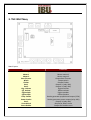
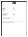
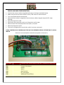
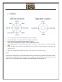
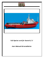
Full Option card for boats R / C User Manual & Installation Content 1. Introduction 2 Features 3 The IBU2 Navy version 4 Connecting and Configuring the radio 5 Commands 6 Changing sounds 7 Configuration Settings 8 Authorized dealers 9 Follow us 1. INTRODUCTION The IBU2 Navy is a multifunction controller for radio-controlled boats, equipped with realistic sound effects and lights all controlled by a 5 or 6 channel proportional radio, AM, FM, or 2.4 Ghz (sold separately). 2 FEATURES The sound effects are completely user definable via microSD card included, allowing customization of the type of boat. Sounds completely synchronized with the functions of the boat, including the starting and stopping of the motor, motor running, Bow Thruster, Winch, Sirens and custom sounds. User settings editable via the microSD card supplied, no special software required. The user can select the use of one or two motors, in case of vessel twin engine latter are controlled in a proportional way during turns. The user can define the maximum speed of each motor from 0 to 100% The user can define the speed limitation of Reverse run from 0 to 100% (based on setting forward speed). Output proportional to the smoke generator (max. 2.5 Ampere) Output power ON / OFF to smoke generator relay (max. 10 Ampere) Output proportional control bidirectional Bow Thruster (max. 2 amperes) Output proportional control bidirectional winch (max. 2 amperes) ESC latest generation, which allows speed control realistic, with its greater efficiency increases battery life. Three relay outputs (max. 10 Ampere each) operated by radio control. Flasher output signals for system status. Protections recoverable by the user, the IBU2 Navy is protected by a 2A fuse for services and a 16A fuse for the section ESC. Monitoring battery voltage to prevent overdischarge and protect the battery, provides visual indication (via the flasher) and sound of the notice of low battery and off motors battery. Supports LiPo 2 and 3 cells, Ni-Cd / Mi-MH, 6 and 8-cell, lead-acid battery 12V. Dual audio amplifier that allows the use of two speakers with separate control for each channel. One channel dedicated to the engine, one channel dedicated to sound effects. Compact size, 115 x 90 x 40mm. Screw terminations which allow up to 18 AWG cable to be connected. 3. THE IBU2 Navy Board layout. Connector Battery Motor 1 Motor 2 Bow Thruster Winch Flasher Out 1 Out 2 Eng. Volume Eff. Volume Engine Spkr Effects Spkr Prop. Smoke Power Smoke Out 3 Servo Winch Servo Rudder Utilization Power Input Motor output 1 Motor output 2 Output Bow Thruster Output winch Output Flasher Output 1 (relay 10A) Output 2 (relay 10A) Engine volume Effects volume Engine speaker Effects speaker Smoke generator proportional output (2.5A) Smoke generator power output (relay 10A) Output 3 (relay 10A) Output for Winch servo Output for Rudder servo SETUP SHEET After installing the card on the model set the dip switches as shown below Motor 1 Enabled (1) Disabled Switch 1 ON OFF Selection engine 2 Enabled (1) Disabled Switch 2 ON OFF Battery Type (2) Li-Po battery (2/3 cells) Ni-Mh or Ni-Cd (6 to 10 cells) Switch 3 ON OFF Programming radio Programming mode Normal Mode Switch 4 ON OFF Cells count (2) 3 cells LiPo, 12V PB, 8-10 cells Ni-Mh/Ni-Cd 2 cells LiPo, 6 cells Ni-Mh/Ni-Cd Switch5 ON OFF (1) If both engines are enabled, during turns will be piloted in proportion to the same tack. (2) Check the battery voltage. When this becomes low alarm sound is played. In addition to low battery warning the boat will turn off automatically. RADIO LINK AND CONFIGURATION Connect the receiver cables (supplied) referring to the figure and table below. Make sure you do not have reverse or dual / rate active on radio channels. Turn on the boat and the transmitter. Wait until the receiver is aligned to the transmitter. (When aligned output OUT1 stops flashing) Move the dip switch 4 ON. Move both the transmitter sticks in all directions until it stops. Move channel 5 & 6 switch/knobs from off/on, min/max. Move the dip switch 4 OFF. The card is configured for use with the radio / receiver connected. CHECK CONTROLS ARE CONTROLLING THE BOAT AS INTENDED BEFORE ATTEMPTING TO USE IN WATER. Receiver connected (cable inserted corresponds to channel 1) Inputs IBU2 CH1 CH2 CH3 CH4 CH5 CH6 Connect to the channel relative to the stick / command you want to use Forward / backward Rudder Winch Bow Thruster On / Off engine Additional Sound Effects 5 CONTROLS Turn on the boat, the output OUT1 flashes (If connected). Turn on the radio, the output OUT1 is steady (If connected). At this point you can activate some features, such as: OUT2, OUT3, output Winch, sounds 1 and 2, additional sounds. Start the engine of the boat (using channel 5) and wait for the motor to start up and motor idles. Move the right stick forward or backward to move, make sure that the boat is moving in the right direction. Move the rudder left and right and make sure it moves in the right direction. NOTE If some of the movements are reversed compared to the command you need to reverse their own channel on the radio (See radio instructions), or change the parameter for the channel in the file "IBU2_TR.ini" in the root of the microSD card inserted into IBU2 (see Chapter 7). Additional controls available from the controller of the radio Sound 1 left stick up (100% of the movement) to play the sound effect 1 Sound 2 left stick down (100% of the movement) to play the sound effect 2 Additional sounds (slider1, 2, 3) move the potentiometer (CH6) to 30% to enable sound slider1, take it to 60% to activate the sound slider2, take it to 100% to activate the sound slider3. Winch left stick in the bottom or top (about 30% of the useful motion) for moving the winch in the desired direction. 6 CHANGE THE SOUNDS On the supplied microSD custom sound effects are provided for one type of boat. Note: To fully enjoy the sound quality you should use a good quality speakers. 4ohm speaker impedance is recommended, although 8 ohm impedance will also work. The amplifier output varies dependent on the battery voltage, 6w @ 7.2v and 10w @ 12v therefore a minimum rating of 6w or 10w speaker is required. To change the set of sounds appropriate to do the following: 1. With the power OFF, press lightly on the microSD inserted under the IBU2 to release the microSD memory card (NOTE: DO NOT PULL THE MICROSD TO UNLOCK !!!), Take it out and put in a memory card reader (not supplied) on your PC, MAC. 2. Access to the memory and browse the content. 3. In the root of the media are the files used by the sound module of IBU2. Note everything in a subfolder is ignored by the IBU2. Each wave sound file is associated with a different sound effect according to the correspondence set in the file "IBU2_NV": Variable in the file IBU2.ini Es. Audio file EngineCold ON Engin Warm ON EngineStop Engine Idle EngineStep 1 EngineStep 2 ... EngineStep XX Alarm1 Bowthruster Bow.wav Bow Thruster Winch Sound1 Sound2 Slider1 Slider2 Slider3 Bbell.wav Corresponding effect estartc.wav estartw.wav estop.wav eidle.wav es01.wav es02.wav Starting a cold engine Starting the engine hot Engine stop Engine idling Motor Ramp 1 Motor Ramp 2 esXX.wav hooga.wav Motor Ramp XX Battery Alarm Winch.wav horn1.wav horn2.wav foghorn.wav seagull.wav Buoy Winch Sirena1 Siren2 Siren fog Gulls Buoy 4. To choose different sound effects simply copy the desired files into the main root of the microSD. Check the name corresponding to the audio samples associated with tags in the file IBU2_NV.INI. 5. Remove the microSD adapter from MAC / PC and put it back in IBU2 until it clicks, turn on the boat and check the new sounds. 6. New sound sets when issued will be available for download at http://www.ibu-electronics.com You can also create your own sounds, replacing the sounds provided by converting a sound effect or music from any format (WAV, MP3) into WAV format, mono, 22050 Hz, 8 bits. Each sample should not be larger than 1 Mb or its reproduction will be truncated. The names of the * .wav files are not important, but you need to keep the correspondence with those reported in the file IBU2_NV.ini as between each file and its sound effect, provided that no more than 8 characters (plus the ".wav" extension ) and do not contain spaces or periods. Example "Abcd_defg.wav" "Abcdefghi.wav" "Ab cd.wav" "Ab.cd.wav" Not good (9 characters); Okay (8 characters); Not good (5 characters, but there is a space); Not good (there is a point in the middle of the name). Note: some audio editing software are not able to successfully convert the audio in this format, or add data that cannot be read by IBU2: If you have problems in the reproduction of its samples, please contact the manufacturer. Also avoid reformatting the microSD provided because some may end up not operating properly when used with the IBU2. 7 CONFIGURATION SETTINGS "IBU2_NV.INI" In addition to the associations of the sound effects with the wave file in the corresponding text file IBU2_NV.INI there are other variables that allow you to customize certain features of IBU2. Configuring the reverse channel radio Each line refers to a specific channel receiver, this function is used, if you are using an older radio (without memory), to avoid having to set (if necessary) the reverse channel according to the trucks that use RadioCH1InverseCmd = FALSE; TRUE FALSE RadioCH2InverseCmd = FALSE; TRUE FALSE RadioCH3InverseCmd = FALSE; TRUE FALSE RadioCH4InverseCmd = FALSE; TRUE FALSE RadioCH5InverseCmd = FALSE; TRUE FALSE RadioCH6InverseCmd = FALSE; TRUE FALSE In this example, all channels have value FALSE this means that no channel is applied on the inversion, or the commands coming from transmitter are reported to the decoding circuit so as sent. Configuring the reverse servo If needed, you can reverse the direction of rotation of the servos, each line is related to a specific channel, this function is used, if you are using an older radio (without memory), to avoid having to set the reverse channels depending on the boat that you are using. SrvRudInverseCmd = FALSE; TRUE FALSE allows to reverse the rudder control SrvWinchInverseCmd = FALSE; TRUE FALSE allows you to reverse the winch control In this example, all channels have value FALSE this means that no channel is applied on the inversion. Moreover the string SrvWinchType = 0 allows you to select the mode of operation of the dedicated servo winch between 0 (normal) or 1 (360°). Accepted values 0, 1 Configure the output OUT 1 The parameter is used to configure the output status OUT1 power Rele1InitialStatus = 1; [OFF 0 - 1 ON] In this case, the output will be active on power, entering the value 0 (zero) will be disabled. (The output can be turned on or off from the transmitter, see Chapter 5) Configuring the maximum current supplied to the engines Parameter: CurrentMotorTreshold = 10; [1..15] Adjusts the threshold of current protection. The default value is 10 Amperes, is possible in case of use of engines can be increased up to a maximum of 15 Ampere the current supplied to each motor. Configuration of the power supplied to the motor The parameters: PowerMotorScaleSx = 100; [1..100]% and PowerMotorScaleDx = 100; [1..100]% Allows to adjust the total output power to the motors during running, this function calibrates accurately the movement speed to approach the real dynamic, a lower value will decrease and vice versa a higher the increase. Configuring the maximum reverse speed The parameter: ReverseSpeed = 50; [1 ... 100]% Used to limit the speed when reversing, a lower value will decrease and vice versa one the highest increase. Note this is proportional to the forward speed selected above. Configuring the smoke generator In case you want to use the smoke generator are two configuration parameters: SmokeInitialStatus = 0; [OFF 0 - 1 ON] This parameter allows you to set the generator, when the boat is turned on, automatically. (The generator can be turned on or off even from the transmitter) In this example the value 0 (zero) means that the smoke generator is OFF when the model is turned ON. The smoke generators have different characteristics from one model to another, so the parameter: MinPwmSmoke = 50; [1..100]% Allows you to determine how much power is delivered to the generator with the engine idling. The command is proportional to the position of the throttle stick. Also on board is a secondary output relay power (max. 10 Ampere) that works in ON / OFF mode. 8 Authorized Dealers Europe / U.K. U.S.: RC Tank Electronics http://rctankelectronics.weebly.com/ http://rc-boat.weebly.com/ Europe / Italy Modeltecnica http://www.modeltecnica.it/catalog/index.php 9 Follow us https://www.youtube.com/channel/UCEp-GZ2yJouc3cszClnuIDg To Follow Design, manufacture and support of the product: I.B.U. by Bretti Ivano http://www.ibu-electronics.com Via Vittorio Emanuele, 70 12048 Sommariva del Bosco Cuneo - Italy C. F. BRTVNI60R03E379T P. IVA 03507690042