1
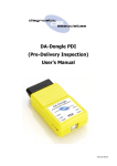
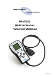
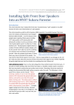
DA-Dongle DTC (DTC Tool) User’s Manual V5.3 02-04-15 2 Contents Important Information 4 General Notice Product Warranty Terms & Conditions Introduction 6 Getting to Know the Device 6 DTC Device Operation 8 DTC Process DTC Model Year Updates DTC Supported JLR Vehicles Installing the DA App Hub 10 Updating the DA-Dongle DTC Device 11 DA-Dongle DTC Software Updating Device Recovery Device Specification 12 Troubleshooting 13 Technical Support 14 Related Products 15 3 Important Information General Notice The DA–Dongle DTC communication interface has been designed and tested to comply with modern vehicle protocols. However, some vehicle models are not in full compliance with these protocols for various reasons. While Diagnostic Associates’ testing and the experience of its many product users have shown the unit to be safe and reliable, there is an inherent risk in using any product that may potentially affect the operation or driveability of your vehicle. If you are concerned about the operation of your vehicle at any time while using these products: Pull off the roadway immediately or as soon as it is safe to do so (if applicable). Disconnect the device from the vehicle OBDII connector. Consult your local car dealership or garage. Report any issues or concerns to our Technical Support Team at [email protected]. We are open Monday through Friday, 7:30 a.m. to 5:00 p.m. GMT, and all queries will be dealt with within a working day. This User Manual is updated on a regular basis to ensure its content is up-to-date. Every effort is made to ensure that the latest version is supplied with your product, however this is not always practical. As a result you should always consult the Diagnostic Associates website to determine if you have the latest version. Product Warranty Diagnostic Associates Limited guarantees that every DA-Dongle DTC device is free from physical defects in material and workmanship under normal use for twelve months from the date of purchase. 4 Product Terms & Conditions In no event shall Diagnostic Associates Limited’s liability exceed the price paid for the product. Diagnostic Associates shall be exempt from all other claims whether based upon direct, indirect, special, incidental, or consequential damages resulting from the use of this product, its accompanying software, or its documentation. Diagnostic Associates Limited makes no warranty or representation, expressed, implied, statutory, with respect to its products or the contents or use of this documentation and accompanying software, and specifically disclaims its quality, performance, merchantability, fitness for any particular purpose. Diagnostic Associates Limited reserves the right to revise update its products, software, or documentation without obligation to notify any individual entity. or all or or or If you are not in agreement with these terms then you are advised to return the product, prior to use, immediately for a full refund. Please direct all enquiries to: Diagnostic Associates Limited Hyde Park House Cartwright Street Hyde Cheshire SK14 4EH UK 5 Introduction Thank you for choosing the DA-Dongle DTC device. This device will attempt to perform a full DTC clear of all stored fault codes on all JLR vehicles from 2005 onwards, related to the CAN networks (and the MOST network if gateway pass-through is supported) only. The device works in a stand-alone mode which means that there is no need for a connection to a PC or the IDS/SDD tool. All of the electronics are contained within the OBDII connector housing, making it a compact and rugged vehicle diagnostic tool. The DA-Dongle DTC can be powered by the USB connector, so there is no need to be connected to the vehicle when updating the device software. However, a vehicle 12V supply on pin 16 on the OBDII connector is required for it to operate correctly during normal operation. Getting to Know the Device Your package includes a DA-Dongle DTC device, a USB 2.0 cable and this user guide. There is no CD for the PC drivers and device update software, as up-to-date versions of these are available from the Diagnostic Associates website at : http://www.diagnostic-associates.com/pages/downloads 6 There are four main parts to the device and these are shown on the picture above. Vehicle OBDII Connector : This is the end that connects to the vehicle OBDII diagnostic connector and provides power to the device and connection to the vehicle communications networks. USB Connector : This connects the device to a PC via a USB (A-B) cable and is used to update the device software when updates are available. LED Status Lights : These are used to give a visual indication to the user as to the state of the device. There are 3 LEDs on the device that are repeated on both sides of the device, these have the following functions. PWR : This indicates that the device is powered up, either via the vehicle if connected to the vehicle, or via USB if connected to a PC. LNK : This indicates the state of the software within the device as well as indicates the device status during reprogramming. STS : This indicates the status of the device during its stand-alone operation. This LED has three colours, RED, GREEN and AMBER. Internal Buzzer : Internal to the device is an 80dB buzzer that is used during device operation to indicate process status 7 DTC Device Operation The DA-Dongle connects directly to the vehicle OBDII (Diagnostic) connector and is a standalone product that requires no other cables during operation. This device does not need to be used with IDS/SDD. Once connected to the OBDII connector the device will attempt to clear all stored faults codes on the CAN networks, and if supported attempt to clear all stored DTC’s on the MOST network (optical network) nodes. It should be noted that this functionality only works in vehicle normal mode, and that any permanent DTC’s may re-log immediately or may require conditions to be satisfied before re-logging. Note: It is assumed that appropriate service actions have been performed on any known vehicle DTC’s prior to any DTC’s being cleared on the vehicle. DTC Process The DA-Dongle DTC device is simple and easy to use, the following procedure identifies the steps required to operate the device on the vehicle. Note: The device works on its own and so does not require to be connected to a PC (or an IDS/ SDD tool) during its normal operation. Please ensure the vehicle is in a safe working mode prior to exercising the following procedure. Connect the DTC device to the vehicle OBDII connector (the device powers from the vehicle). The device enters trigger mode – flashing red/green status (STS) LED. The trigger is for the operator to switch on the vehicle ignition. The application begins to run, this is shown by a green flashing status (STS) LED. Once complete the status (STS) LED turns solid green and the device emits a constant highpitched audible tone to ensure the operator removes the device from the vehicle. Note: If the process fails for whatever reason, the status (STS) LED turns solid red and the device emits a high-pitched audible tone. At this time the process should be repeated ensuring that all conditions for the process have been met. The process completes in approximately 10 seconds. The following pages of this manual will identify how to install the DA Software Update Tool, and how to update your DTC device. 8 DTC Model Year Updates The software associated with the DA-Dongle DTC device is updated periodically to increase its coverage for new JLR vehicles and model year updates. You can check for these updates by connecting your device to a PC via the supplied USB cable, and launching the DA Software Update Tool. This tool will connect to the Diagnostic Associates file server and check to see if a newer version of the DTC software is available to download. DTC Supported JLR Vehicles The following JLR vehicles and associated model years are supported by the DTC device at the time this user manual was produced. To obtain an up-to-date version of this table you should visit the Diagnostic Associates website. Jaguar & Land Rover Vehicle Coverage DA-Dongle - DTC Clear Vehicle / Model Year MY05 MY06 MY07 MY08-09 MY10-11 MY12-13 MY14 MY15 MY16 Defender - - - - - - - - - Discovery / LR3/ LR4 Yes Yes Yes Yes Yes Yes Yes Yes Yes Range Rover Sport Yes Yes Yes Yes Yes Yes Yes Yes Yes Range Rover - Yes Yes Yes Yes Yes Yes Yes Yes Freelander / LR2 - - Yes Yes Yes Yes Yes Yes - Evoque - - - - - Yes Yes Yes Yes Discovery Sport - - - - - - - Yes Yes XJ - New - - - - Yes Yes Yes Yes Yes XJ - Old - - - - - - - - - XK - New - - Yes Yes Yes Yes Yes Yes - XK - Old - - - - - - - - - XF - - - Yes Yes Yes Yes Yes - XE - - - - - - - - Yes F-Type - - - - - - Yes Yes Yes S-Type - - - - - - - - - X-Type - - - - - - - - - (Yes) - Covered for MY : (-) - N/A 9 Installing the DA App Hub The DA App Hub is a PC based application that is installed on your PC which will allow you to check for software updates to your DA-Dongle device, and to download them to your device directly, via the USB cable. The PC that this application is installed on should be connected to the internet as the installed application will connect to the Diagnostic Associates file server to check for and download device software updates. Note: The DA App Hub is supported on Windows 7 (32 bit/64 bit). Windows XP, Windows Vista (32 bit/64 bit) and It is important to install the DA App Hub software before plugging your DA-Dongle device into your computer. Note: The following steps may differ slightly dependent upon the operating system or components that are installed on your computer, but in general these are standard install steps. 1. Download the 'DAAppHub_Vx.x.x.zip' from: http://www.diagnostic-associates.com/pages/downloads The version number x.x.x will be the latest available for all the Diagnostic Associates devices. 2. Unzip the files to a folder on the PC that will be used to update the device software. 3. Double-click on the setup.exe file, to begin the installation. Note: If you do not have the Visual C++ 2010 Runtime Libraries (x86/x64) installed you will be automatically prompted to install these now. When the Visual C++ 2010 installation is complete the DA App Hub Setup Wizard installation will begin. 4. Choose a location to store the files. You may either leave the default installation folder or choose your own and then confirm the installation. The DA App Hub will now install. 5. A window will pop up asking if you wish to install the DA Device drivers - click ‘Yes’ as this is part of the installation process. Also, during this part of the process two MS-DOS style windows will pop-up and may remain on your screen for some time (even after the main installation application is at the installation complete stage), this is perfectly normal. Do not attempt to close the MS-DOS style windows manually as this will prevent the DA device drivers being installed successfully, they will close automatically when the device driver install is complete. 6. Plug your DA-Dongle device into your computer using the supplied USB cable. The device will automatically be recognised by Windows and is now ready for use. 7. Your DA App Hub is now ready for use, it can be run either from the Start Menu or the Desktop short-cut. 10 Updating the DA-Dongle DTC Device Periodically Diagnostic Associates will release updates to its products drivers and software. These updates are necessary to either release further device functionality, resolve any field issues that have been highlighted, or to ensure that the devices are working correctly with OEM software. If you are experiencing any problems during device use, always make sure that you have the latest device software and drivers. DA-Dongle DTC Software Updating Note: An internet connection is required to update your DA-Dongle device as the software automatically downloads the latest versions of software from the Diagnostic Associates file server. 1. Connect your DA-Dongle to your PC using the supplied USB cable only. Note: The device should NOT be connected to the vehicle when updating the device software. 2. Run the DA App Hub using either the Start Menu or the Desktop short-cut. 3. The first ‘tab’ of the application you see will be the Home tab. This contains information about the status of your DA-Dongle software. 4. Selecting the ‘Update Applications’ tab will allow you to update your DA-Dongle software as follows. 5. Details of your DA-Dongle device will appear in the centre of the application window. The information window at the bottom of the application will inform you if an update is available or if your DA-Dongle is already up to date. 6. If an update is available you can click ‘Update Device’ and the DA App Hub will update your software to the latest level. When you click 'Update Device' the information box will display the various stages required to update the software on your DA-Dongle. The progress bar will also indicate progress through the various stages. It is important that when you click 'Update Device' that you do not disconnect the DA-Dongle from the PC until the process is completed. 5. Finally your device will 'Reboot', this will cause it to re-enumerate on your PC, you may notice messages popping up from the system tray at this time. When complete the information window will display the message ‘Your software is up to date’. Your DA-Dongle device is now fully updated and ready for use. 11 Device Recovery The DA-Dongle device has the ability to check the integrity of its own loaded software. It does this as soon as the device is powered up. If after powering-up your device the yellow LNK LED is flashing steadily and then illuminates constantly, then this means that the software on the device is corrupt. In order to re-load the device software, simply follow the DA-Dongle DTC Software Updating procedure shown on page 11 of this document. Device Specification The DA-Dongle DTC device has the following pin-out connections. FUNCTION ODBII pin no. 125K CAN +ve 500K CAN +ve 125K CAN -ve 500K CAN -ve VBatt +ve VBatt -ve 1 2 3 S/W 4 H/W 5 H/W 6 S/W 7 8 9 10 11 S/W 12 13 14 S/W 15 16 H/W S/W = Multiplexed Pin H/W = Hardwired Pin The device has the following electrical characteristics: Vehicle Battery Range = 8V to 36V Operating Current = 60mA (nominal) All Vehicle communication interfaces are multiplexed 12 Troubleshooting The DA-Dongle gets its power from either the vehicle (for vehicle communications) or a PC USB port (for device re-programming). There are LED’s repeated on both side of the device that are used to indicate the device status. If an LED is not working when it’s corresponding pair LED is, then the device will still be working correctly, however the other LED will be faulty and will need replacing eventually. If the LNK LED has a slow flashing light which then goes out after 30 seconds, then the device loaded software was corrupt but was automatically re-loaded from the device, and can be now used as normal. If the LNK LED has a slow flashing light which then turns on continuously after 30 seconds, then the device loaded software is corrupt as well as its backup copy, and you will need to download new software onto the device. If the STS LED is flashing RED then GREEN when powered via the ODBII connector, then this means that the device has past its self-test and is in its trigger mode ready for operation. If the STS LED is flashing GREEN, then the device is connected and is communicating correctly with the vehicle. If the PC displays a ’Device Not recognised’ message when connecting the device to the PC, then this probably indicates that there is a problem with either the device drivers on the PC or the software on the device (or possibly the USB cable). It is advisable to re-install the drivers and software on both of these to ensure that they are up-to-date and compatible drivers and software are installed. If no LEDs are lit, this may indicate a failure of the device. Try connecting your device to another computer. If no LEDs light up on the device during this second test, then contact technical support. The device does not power correctly when powered via USB, or a windows message appears saying the that there is a surge on the USB HUB, then this may be as a result of too many higher powered USB devices on the PC USB. To overcome this simply disconnect other USB devices from your PC until the device powers on. If the problem persists then the device could be faulty and should be returned for repair. If the STS LED turns RED during device operation on the vehicle and the buzzer emits a pulsating tone, then this indicates that the process has failed and should be repeated. If the STS LED turns solid GREEN or RED during device operation on the vehicle, and the buzzer does not sound during this phase, then the buzzer is faulty and should be eventually replaced. If any of these issues have been addressed and verified, and you are still having trouble, email [email protected] with a summary of the problem and we will endeavour to resolve your issue as soon as possible. 13 Technical Support Diagnostic Associates Limited are open Monday through Friday, 7:30 a.m. to 5:00 p.m. GMT, to answer technical support questions. If you need assistance please email [email protected]. If technical support finds it necessary to return your device for repair, you will be asked for your contact information and provided with a Return Merchandise Authorization number (RMA) that Diagnostic Associates will use to track the unit through the repair department back to you. Please write this number on the outside of your shipping box so it can be directed to the correct department. Note: If the necessary repair is not covered by Diagnostic Associates warranty, and you still wish to have the unit repaired, then you will be contacted for payment arrangements to allow this to happen. 14 Related Products Diagnostic Associates Limited has several JLR approved products available for data acquisition, diagnostics, development, testing, and reprogramming for modern vehicles. Visit www.diagnostic-associates.com for more information on these products. 15